DOI:10.32604/csse.2022.019585
| Computer Systems Science & Engineering DOI:10.32604/csse.2022.019585 | |
| Article |
Novel Compact UWB Band Notch Antenna Design for Body-Centric Communications
1Department of Electrical and Computer Engineering, North South University, Bashundhara, Dhaka, 1229, Bangladesh
2Department of Computer Science, College of Computers and Information Technology, Taif University, P.O. Box 11099, Taif, 21944, Saudi Arabia
3School of Electronics & Electrical Engineering, Lovely Professional University, Punjab, India
4Department of Computer Engineering, College of Computers and Information Technology, Taif University, P.O. Box 11099, Taif, 21944, Saudi Arabia
*Corresponding Author: Mohammad Monirujjaman Khan. Email: monirujjaman.khan@northsouth.edu; monirkhan.qmul@gmail.com
Received: 18 April 2021; Accepted: 24 May 2021
Abstract: This research analyzes and implements an innovative and tiny ultra-wideband (UWB) antenna with band-notched features for body-centric communication. The shape of the designed antenna looks like a ‘swan’ with a slotted patch. Computer Simulation Technology (CST) is used to assess and investigate the performance of this antenna. With a band notch, this antenna can prevent interference from Wireless Local Area Network (WLAN) (5.15–5.825 GHz) and Worldwide Interoperability for Microwave Access (WiMAX) (5.25–5.85 GHz) systems. At first, the performance parameters like return loss response, gain, radiation patterns, and radiation efficiency of this UWB antenna are evaluated. After that, the human body effects on the antenna performance of the antenna are also examined to place the antenna at various distances away from 3-layers of phantom body model at different frequencies. All the on-body performance parameter results are compared and analyzed with free space performance parameter results. Lastly, by changing patch slot length and ground plane length, parametric studies were done for performance comparison. According to this research, it is noticed that the antenna is tiny and new. It shows good performance in body case as well. Hence, the antenna is very suitable for healthcare applications.
Keywords: Band notch; compact size; ultra wide band antenna; novel antenna; on-body; body-centric communications; computer simulation technology (CST)
Because of its unique properties, UWB technology has attracted both academics and industry in recent years. UWB communication has grown in popularity and innovation as a means of transmitting high-speed data across short distances. UWB technology allows for higher data rates and lower power emissions, as well as improved efficiency. Furthermore, constructing UWB networks needs less effort and difficulty, which has piqued the interest of many academics in this field; as a result, designing UWB antennas is growing increasingly famous by the day [1]. In healthcare applications for remote patient monitoring, UWB communication has a lot of potential in body-centric communications (BCWCs). The body-centric wireless network (BCWN), which is utilized in medical services to track patient’ varied physical conditions, uses many sensors with multiple units spread all through human body to acquire important physiological data [2–3]. The measured physiological data captured and acquired by the sensors scattered across the human body will be sent to a human body worn access point. Antennas, on the other hand, are critical in BCWCs since they help to increase the efficiency of radio communications. The scope of BCWNs includes anything from chronic illness care for people and senior care to fundamental well-being monitoring and different sporting performance studies [2–4].
The Federal Communication Commission (FCC) announced in 2002 [5] that the frequency allotment for unregulated UWB data transmission has been increased from 3.1 GHz to 10.6 GHz, which has sparked a lot of interest in the field. Because of UWB’s high frequency range, antennas for this spectrum are tiny, which is ideal for wearable electronics [6–7].
There is a threat that interferes with the UWB system. That interference makes a device inefficient because of many narrow frequency bands such as (5.2 GHz and 5.7 GHz) of different wireless communication systems [8]. Therefore, avoiding interference with these frequencies in the UWB ranges is essential. To avoid interference, a band-notch feature is needed for the UWB antenna. Ultra-wideband and wearable technology needs compact size due to longer battery life and power-efficient communication without interference. The band notch is simply a band-rejection filter that allows many signal to pass unmodified while suppressing those in a particular range to minimal levels. As a result, a good antenna may be made to disregard the interference frequency. The primary goal of this research is to create a unique and small UWB notch wearable antenna for BCWC for e-health applications. The antenna will work in the UWB frequency ranges and reject unwanted narrow frequency bands. To develop energy-efficient connections among nodes scattered throughout the human body and also with off-body components, the antenna should be less sensitive to the existence of human lossy body tissues.
In [9–11], ultra-wideband wearable antennas for body-centric wireless communication have been presented. The antennas are compact and show good on-body performance. UWB on-body radio communications using different antennas have been investigated in [12–13]. Other particular frequency bands (5.2 GHz and 5.7 GHz) for various wireless communication systems generate interference in the UWB frequency spectrum. A band-notch technique is required to design interference-free, power-efficient communication. In [14–20], authors have presented UWB band notch antennas with different techniques for different frequency bands. They have also used the EBG technique for UWB band notch characteristics on the antenna structure. However, there is a minimal study of UWB band-notch antenna for wearable application in body-centric communications. In UWB on-body communications, wearable antennas need to be smaller in size and less interference to provide power-efficient communication. This paper proposes a very compact and novel band notch (5.2 GHz–5.8 GHz) antenna and designed using CST tool in the free space environment. The proposed antenna is novel because of the structure and band notch characteristics in the UWB frequency range. For UWB band notch wearable body centric communications, this novel shape antenna has not been proposed by any authors in the literature. In order to avoid interfering in the UWB resonance frequencies, the antenna configuration has a U-shaped slot. After investigating the antenna’s free space performance for real-life realization, the antenna performance is evaluated on the human body modeled with a three-layer model. The antenna’s operation in air as well as on the body was studied. However, the antenna is very less sensitive to the human body. The advantage of this antenna is that it has compact size, novel structure, band notch characteristics in the UWB frequency range. The antenna has excellent on-body performance, making it suited for UWB BCWCs with minimal interference.
The rest of this paper is organized as follows: Section 2 of this work discusses UWB band notch proposed antenna. The antenna’s simulated performance characteristics are presented in section 3. The antenna was studied on a human body model in section 4. Section 5 presents distance variation on body performance parameter study. Section 6 is dedicated to parametric study, and finally, in section 7 conclusion is discussed.
2 UWB Band Notch Antenna Design
Figures 1(a) and 1(b) depict the antenna’s front and back orientations, respectively. The shape of the designed antenna looks like a ‘swan’ with a slotted patch. This antenna consists of three planer parts; the patch (radiating element), substrate, and the ground plane. The width and length of the substrate are the same. The suggested antenna’s substrate is 25 × 25 mm in overall dimension. Tab. 1 shows the summary of the dimensions of the proposed antenna. The wavelength of the antenna at the centre frequency of 6.85 GHz is 43.80 mm. The electrical size of the substrate is
The feed line is 10 mm long and 2.5 mm wide. The feed-line Microstrip width is fixed at 2.5 mm for 50-Ω impedance from 3.2 GHz to 11 GHz. The thickness of the patch layer is 0.035 mm. The substrate height is 1.139 mm. The antenna’s rectangle bottom layer is 9 mm long and 25 mm wide and is located on the underside. The antenna has a 0.035 millimeter thick radiating component. The gap, which provides adequate management between both the bottom edge patch and the ground plane, is used to specify the distance between both the rectangular patch and the ground plane printed on the back of the substrate for optimal bandwidth balancing. This CST software is very user-friendly and reliable. On the base of the antenna’s feed line is a waveguide port with a length of 9.5 mm and a height of 8.1219 mm.
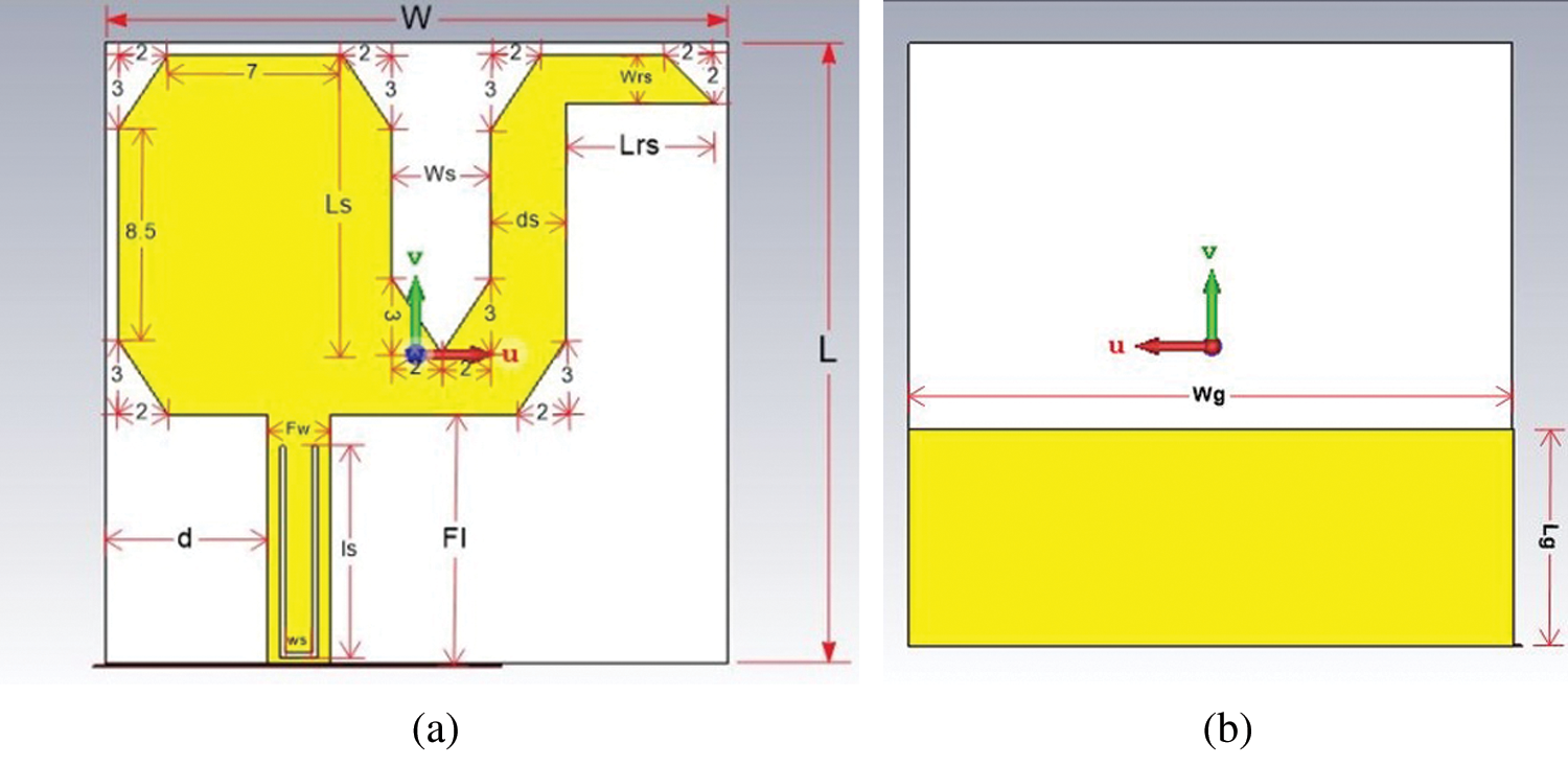
Figure 1: The designed UWB band notch antenna, from the (a) front and (b) back.
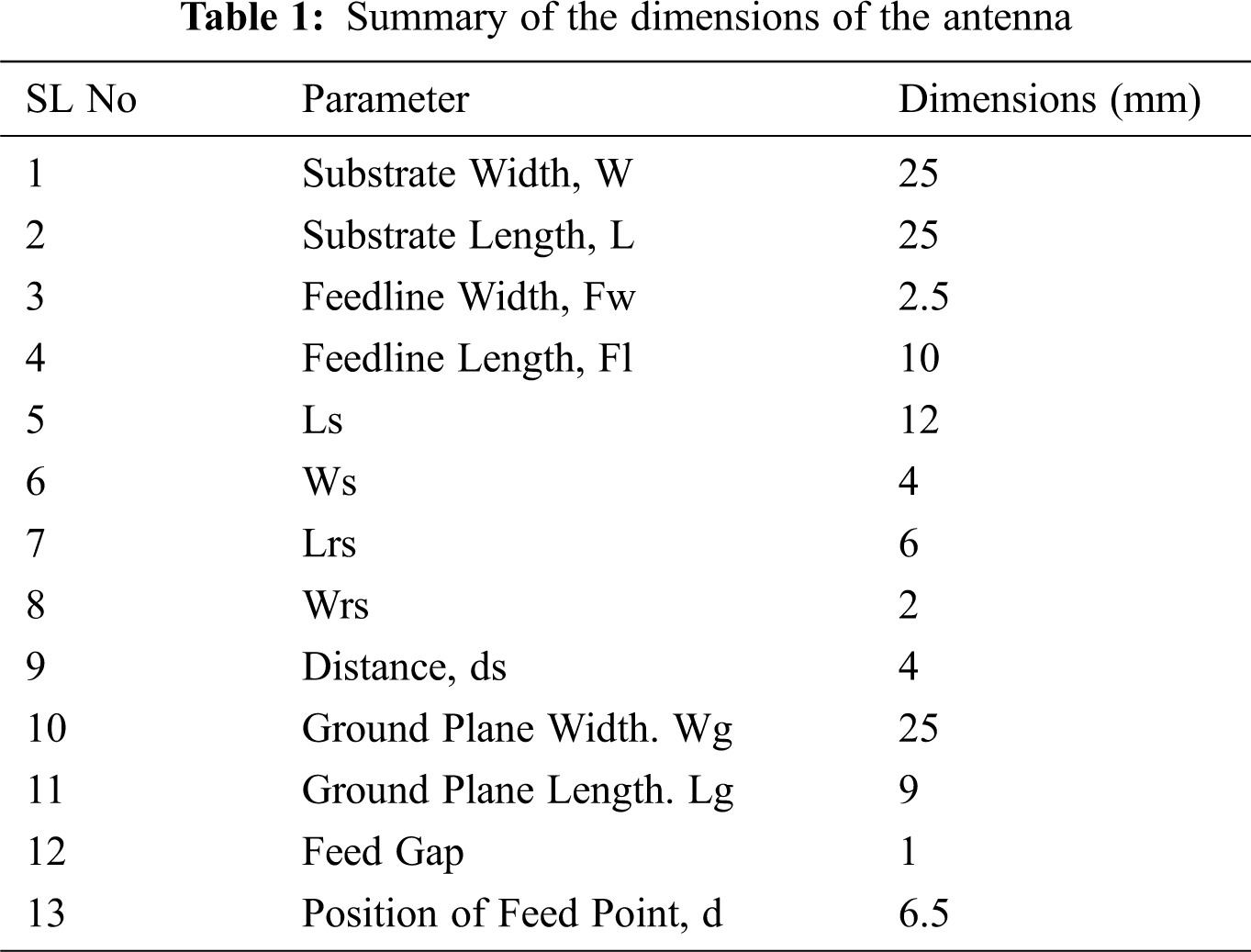
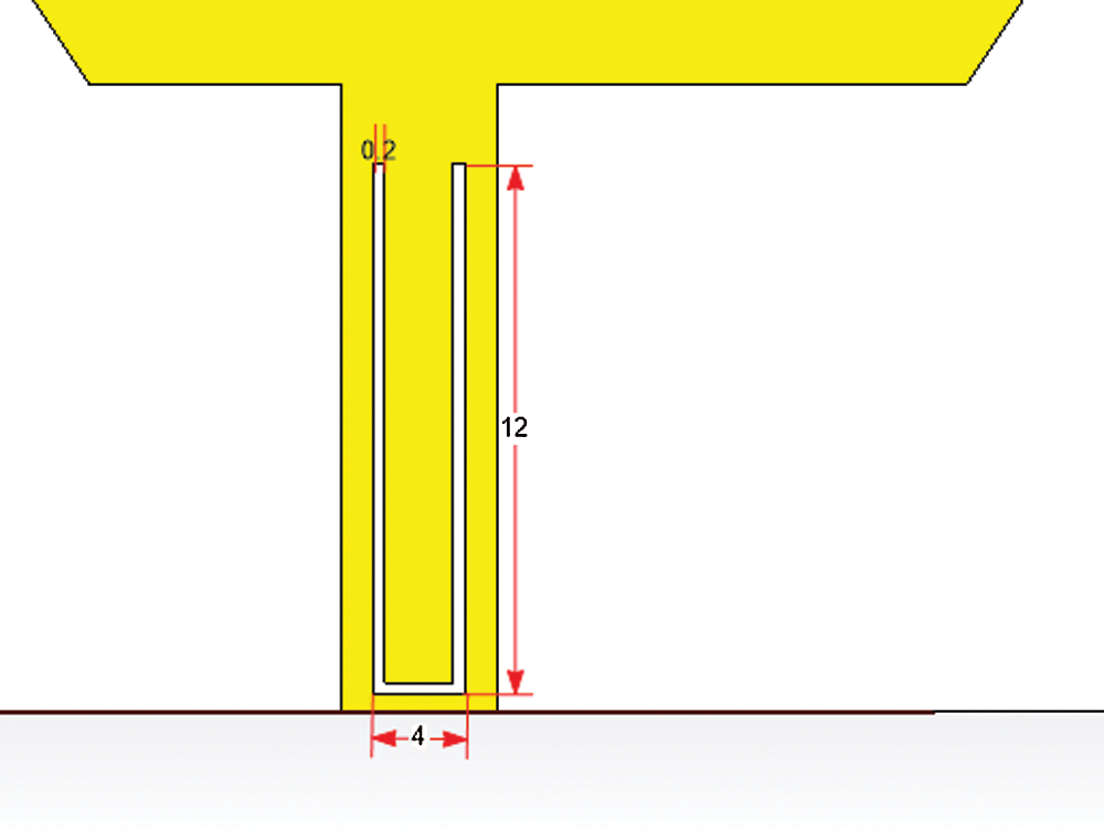
Figure 2: Dimension of slot on the feed line
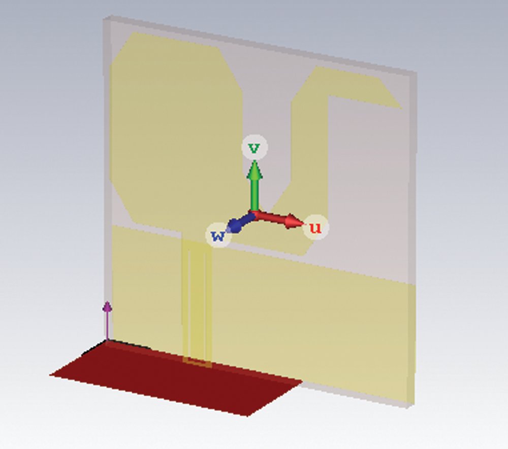
Figure 3: Waveguide port of the proposed antenna
3 Free Space Performance of UWB Band Notch Antenna
For free space simulation, different performance parameters of the designed antenna were done by Computer Simulation Technology Microwave Studio electromagnetic simulator (CST MWS) tool.
Return loss is one of the prime parameters to measure antenna performance. The antenna’s free space return loss curve is shown in Fig. 4 below. The antenna has quite a good bandwidth of 3.2 GHz to 11 GHz and a return loss curve of less than −10 dB, which includes a spectrum notch that covers the region of 4.5 GHz to 6.1 GHz and efficiently avoids interference with existing WLAN and WiMAX systems. This band-notch characteristic makes this novel antenna suitable for power-efficient and interference-less communication in wireless wearable body sensors networks.
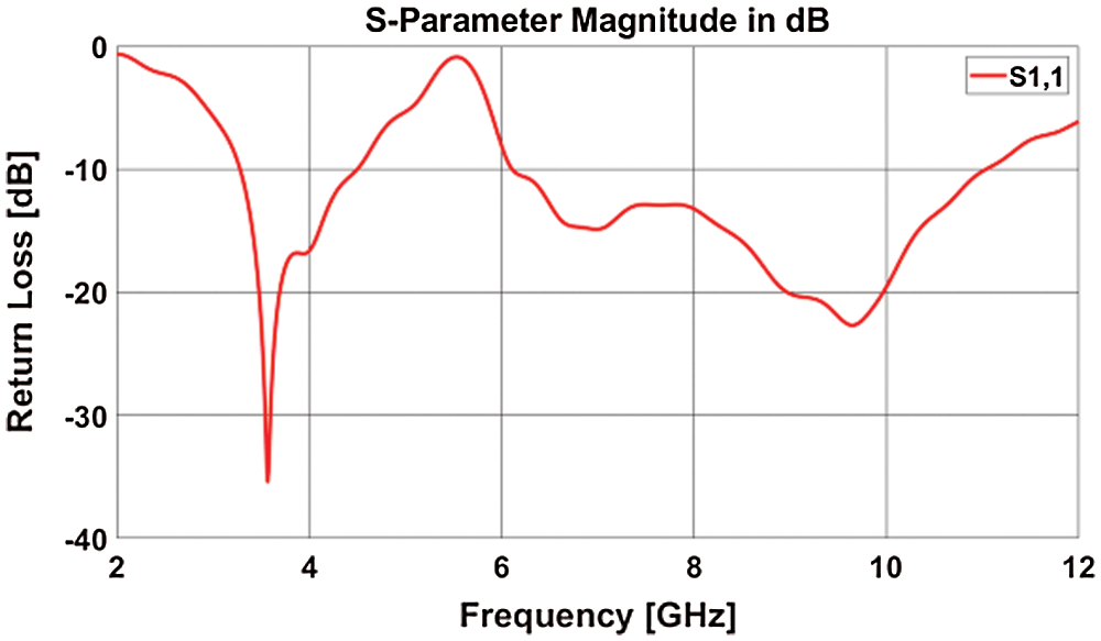
Figure 4: The antenna’s return loss curve.
3.2 Gain, Radiation Efficiency and Radiation Pattern
Antenna gain, radiation efficiency, and radiation pattern are simulated for 3.5 GHz, 5.2 GHz, 5.8 GHz, 8 GHz, and 10 GHz. A maximum gain of 3.454 dBi is achieved at frequency 10 GHz during the free space simulation. 95.97% of radiation efficiency is found at frequency 3.5 GHz. Tab. 2 shows free space gain and radiation efficiency for different frequencies. The three-dimensional (3D), E, and H plane radiation patterns are shown in Figs. 5, 6, 7, 8, and 9. At 5.8 GHz, due to band notch, the lowest radiation efficiency of 69.76% is noticed, and that is expectable. The radiation patterns of this antenna at most of the frequencies look nearly omnidirectional. However, at 10 GHz, the radiation looks a bit distorted. Previous studies have noted that for UWB antenna cases, the radiation pattern at higher frequencies shows distorted behavior.
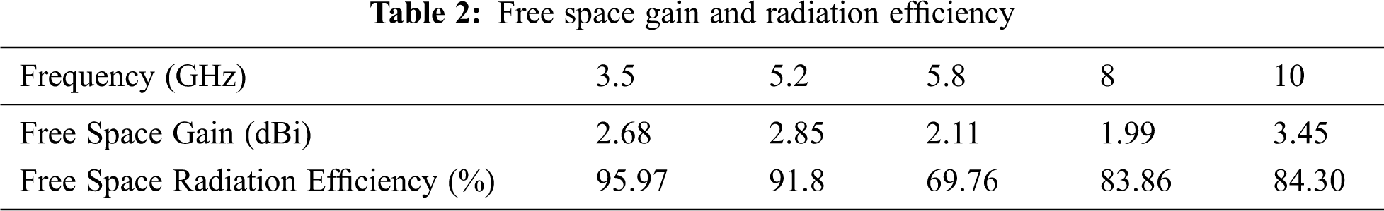
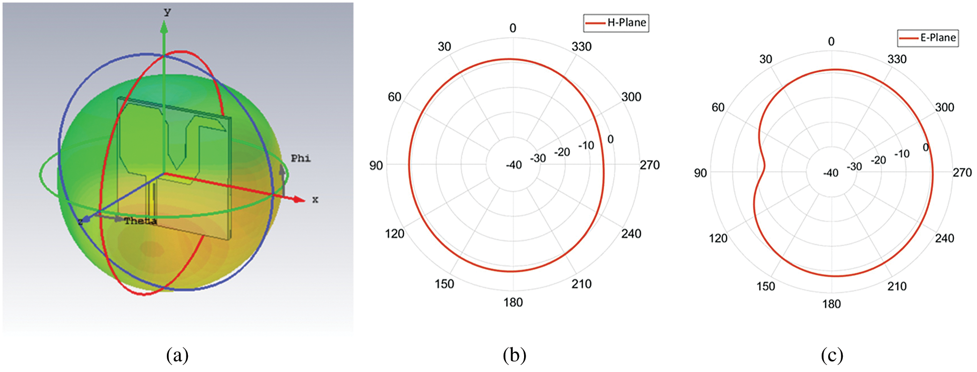
Figure 5: Free space radiation pattern at 3.5 GHz. (a) 3-D Pattern (b) H-Plane (c) E-Plane
Figure 6: Free space radiation pattern at 5.2 GHz. (a) 3-D pattern, (b) H-plane and (c) E-plane
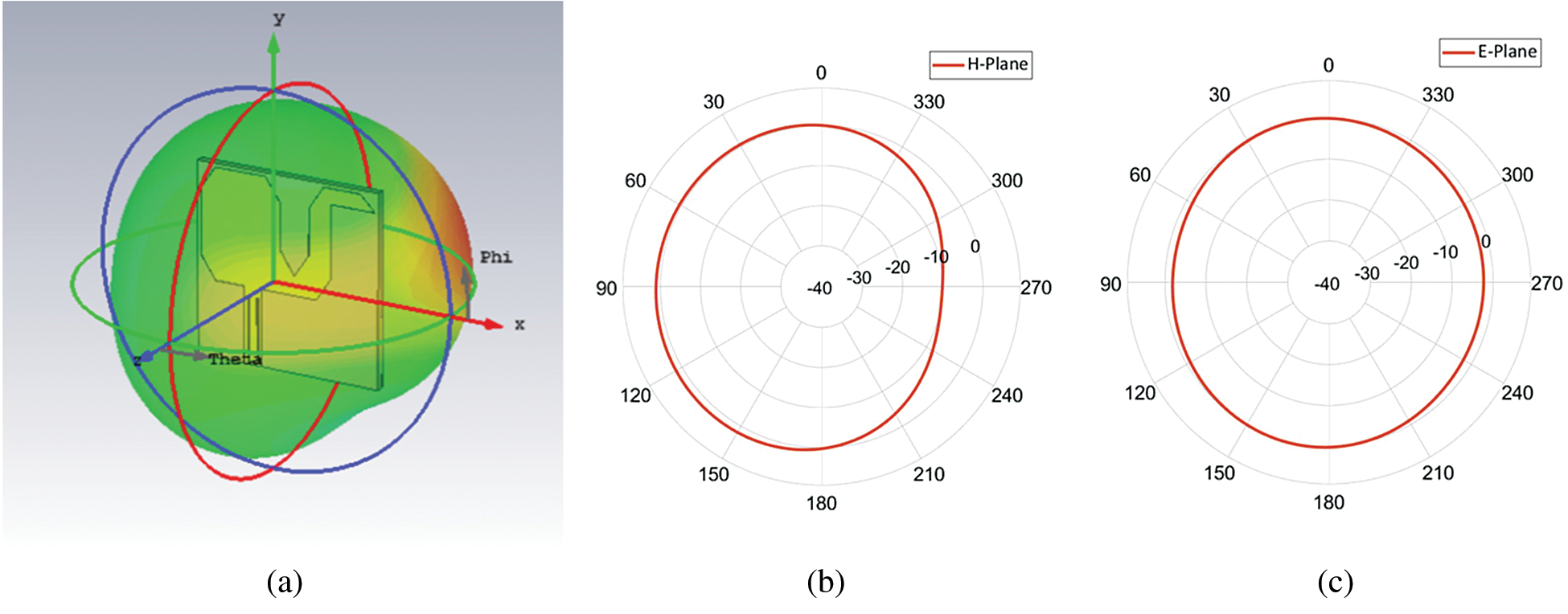
Figure 7: Free space radiation pattern at 5.8 GHz. (a) 3-D Pattern (b) H-Plane (c) E-Plane
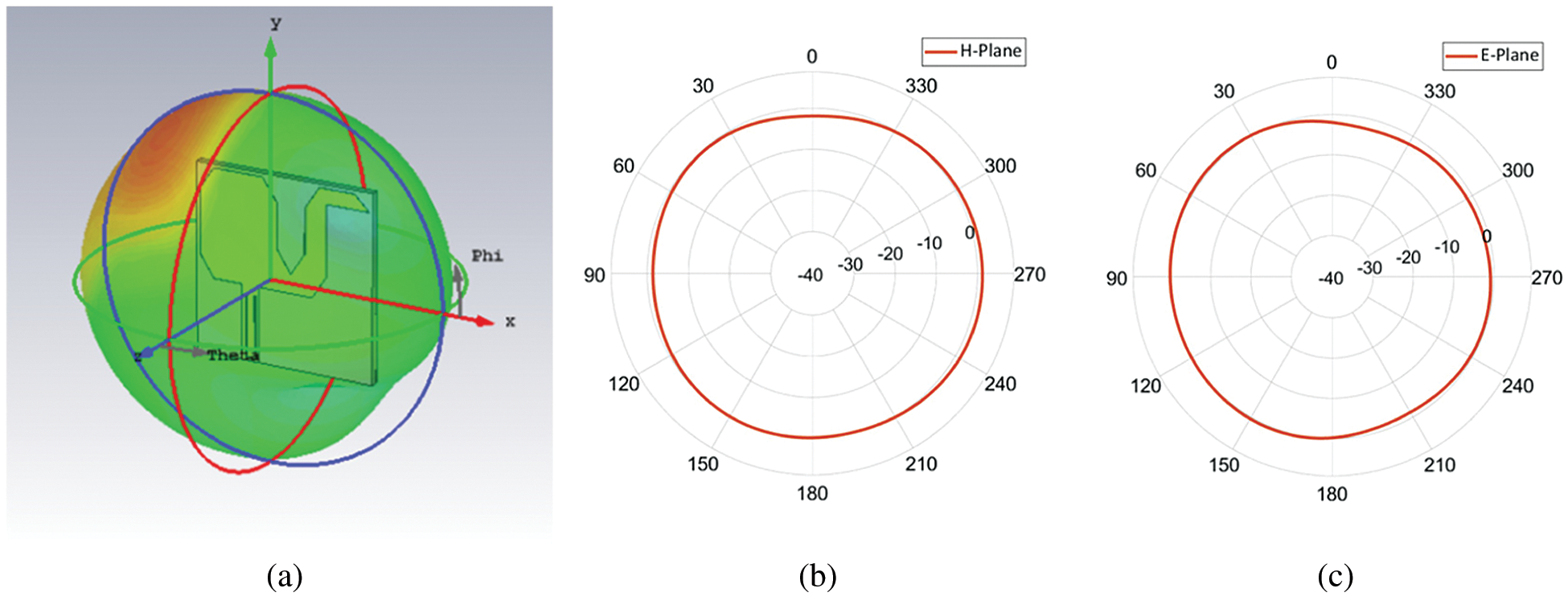
Figure 8: Free space radiation pattern at 8 GHz. (a) 3-D Pattern (b) H-Plane (c) E-Plane
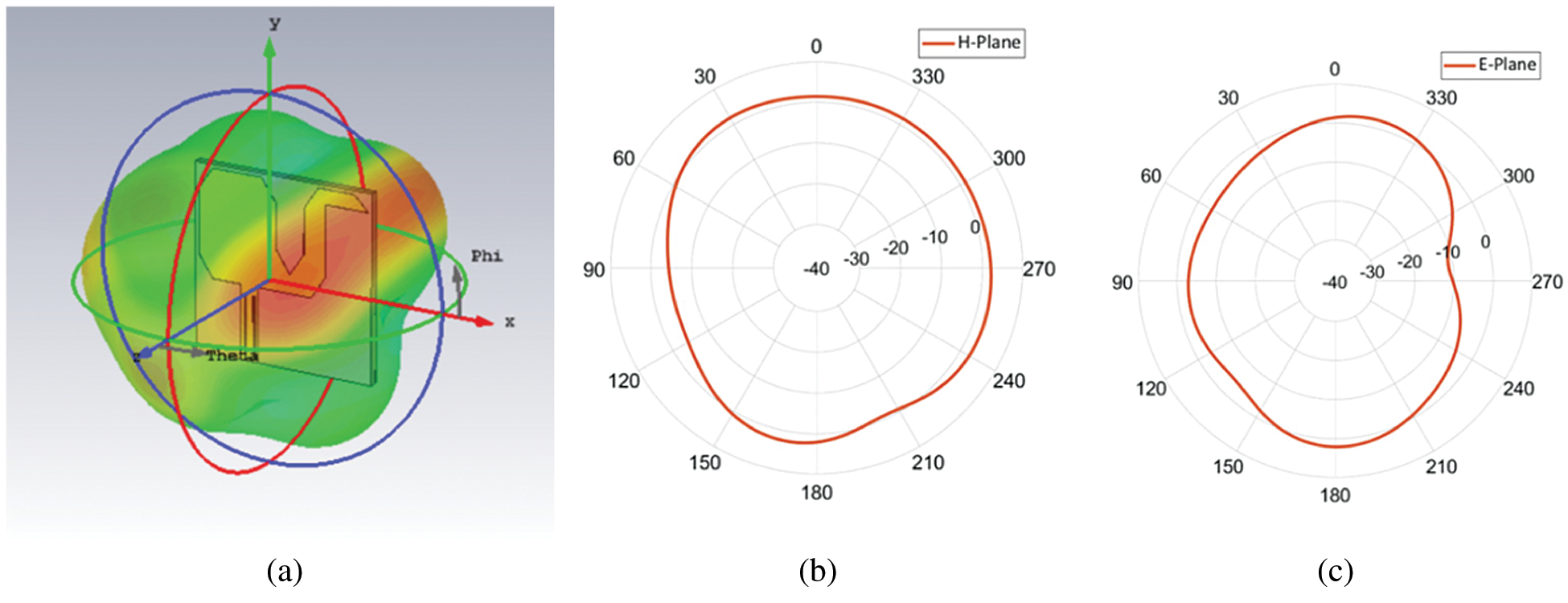
Figure 9: Free space radiation pattern at 8 GHz. (a) 3-D Pattern (b) H-Plane (c) E-Plane
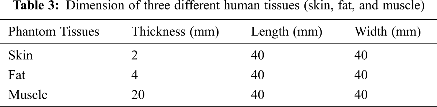
The antenna was mounted on the torso phantom body model for on-body simulation to study the effect of the phantom body on antenna parameters, as illustrated in Fig. 10. The selected phantom body design in this work comprises of the 3 outermost layers of a human body (skin, fat, and muscle). The average depth of adult human skin is about 2 mm, fat is about 4 mm, and muscle depth is about 20 mm. Tab. 3 shows the dimension of three different human tissues (skin, fat, and muscle). Fig. 10 depicts the antenna arrangement as well as a three-layer human body structure.
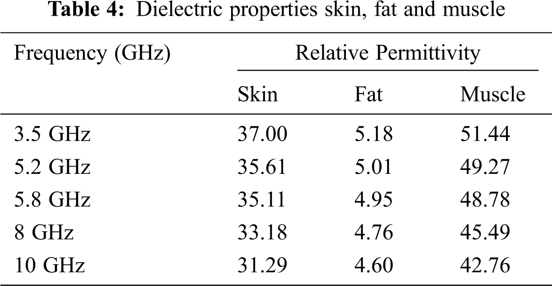
During simulations, a 4 mm gap was realized between both the antenna and the first layer (skin) of the phantom model. The dielectric characteristics of the human body fluctuate with frequency, resulting in dispersed tissue demonstration [21]. The relative permittivity and electric conductivity of all the layers of the human body model where skin, fat and muscle formation is determined during the CST simulations. Tab. 4 shows the values of dielectric properties (relative permittivity) of different tissues like skin, fat, and muscle for various frequencies 3.5 GHz, 5.2 GHz, 5.8 GHz, 8 GHz, and 10 GHz.
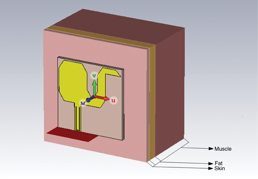
Figure 10: Proposed Antenna with Phantom Body Model (Skin, Fat, and Muscle)
In comparison to free space, the return loss has shifted a bit after positioning the antenna just above phantom body model. Figure 11 illustrates a comparison of the return loss curves in free space and at a distance of 4 mm from the body model. The whole on-body return loss graph was somewhat left-shifted, but the notched frequency band remained within the intended range, as seen in Fig. 11.
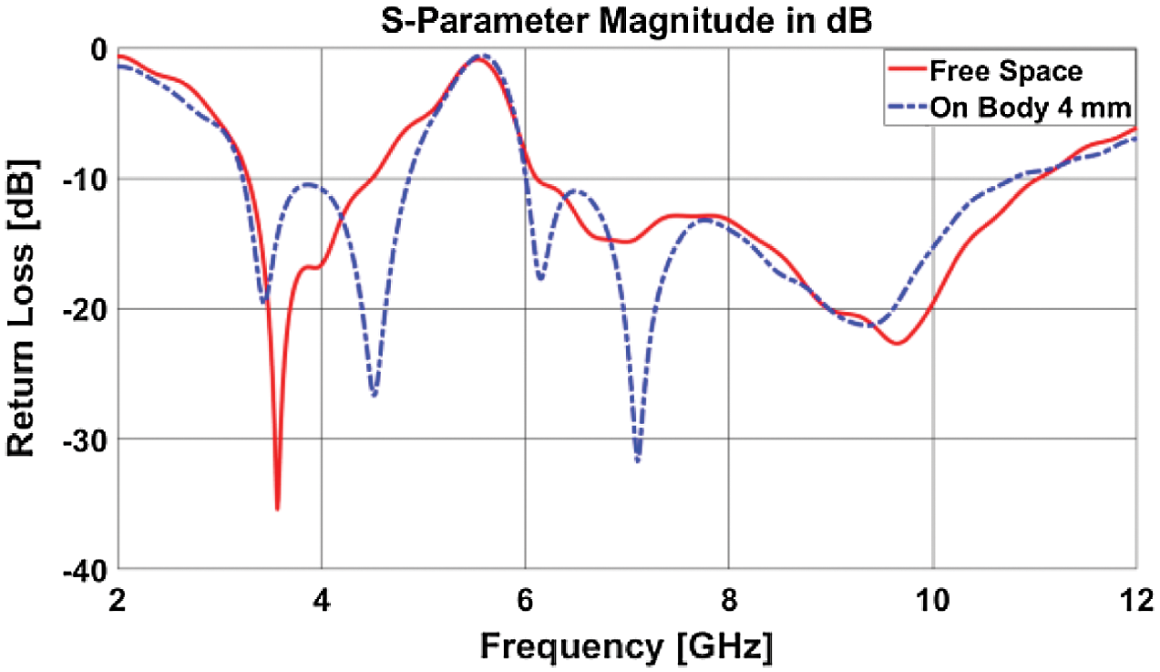
Figure 11: Comparison of return loss curve between the free space and 4 mm distance away from on body responses of the proposed antenna
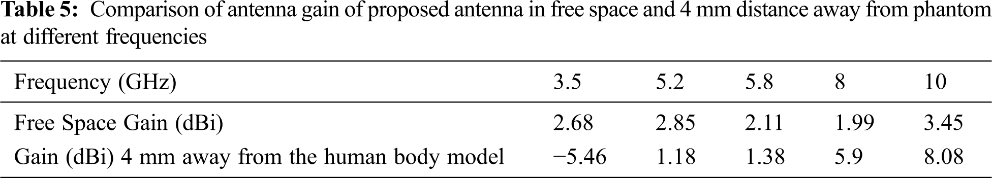
Antenna gain at both 4 mm distance away from on-body and free space is simulated and compared at different frequencies. Tab. 5 listed the comparison of gain of proposed antenna. From the table, it is seen that at 3.5 GHz, the antenna gain is very poor at a 4 mm distance away. For other frequencies, the antenna gain is good enough for wearable applications with good power transmission. Except for the band-notch region, the antenna performance is quite good, and in the band-notch region, it is inactive and desirable and expected. This is the objective of band-notch features in the UWB antenna design.
4.3 Antenna Radiation Pattern Comparison
The designed antenna's radiation patterns are first examined in free space simulation and then on a phantom model that is 4 mm away from the antenna. All the radiation patterns are monitored in both azimuth and elevation planes. Azimuth is the top-down view of the radiation pattern which is spread out horizontally (H-plane for horizontal) Elevation is the side view of the antenna and its vertical radiation pattern (E-plane is for elevation). The radiation patterns of free space and on-body were shown in Figs. 12, 13, 14, 15, and 16 when the antenna was positioned 4 mm away from the phantom of the proposed antenna. The free space radiation patterns of these different frequencies present mostly omnidirectional patterns. In contrast, on-body radiation patterns show slightly irregular on both planes as phantom body tissues act as a lossy medium that absorbs radiation. Figs. 12 to 16 blue color shows the free space radiation patterns, and the red color represents the on-body radiation patterns for both E and H planes.
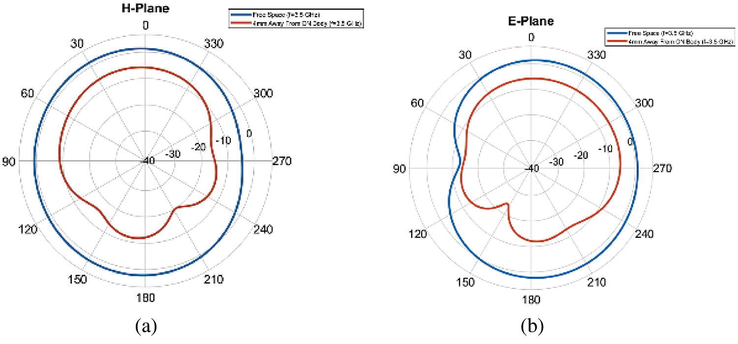
Figure 12: At 3.5 GHz, a comparison of radiation patterns: (a) On H-Plane and (b) On E-Plane
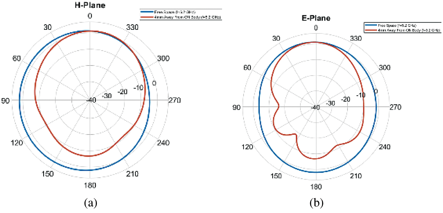
Figure 13: At 5.2 GHz, a comparison of radiation patterns: (a) On H-Plane; (b) On E-Plane
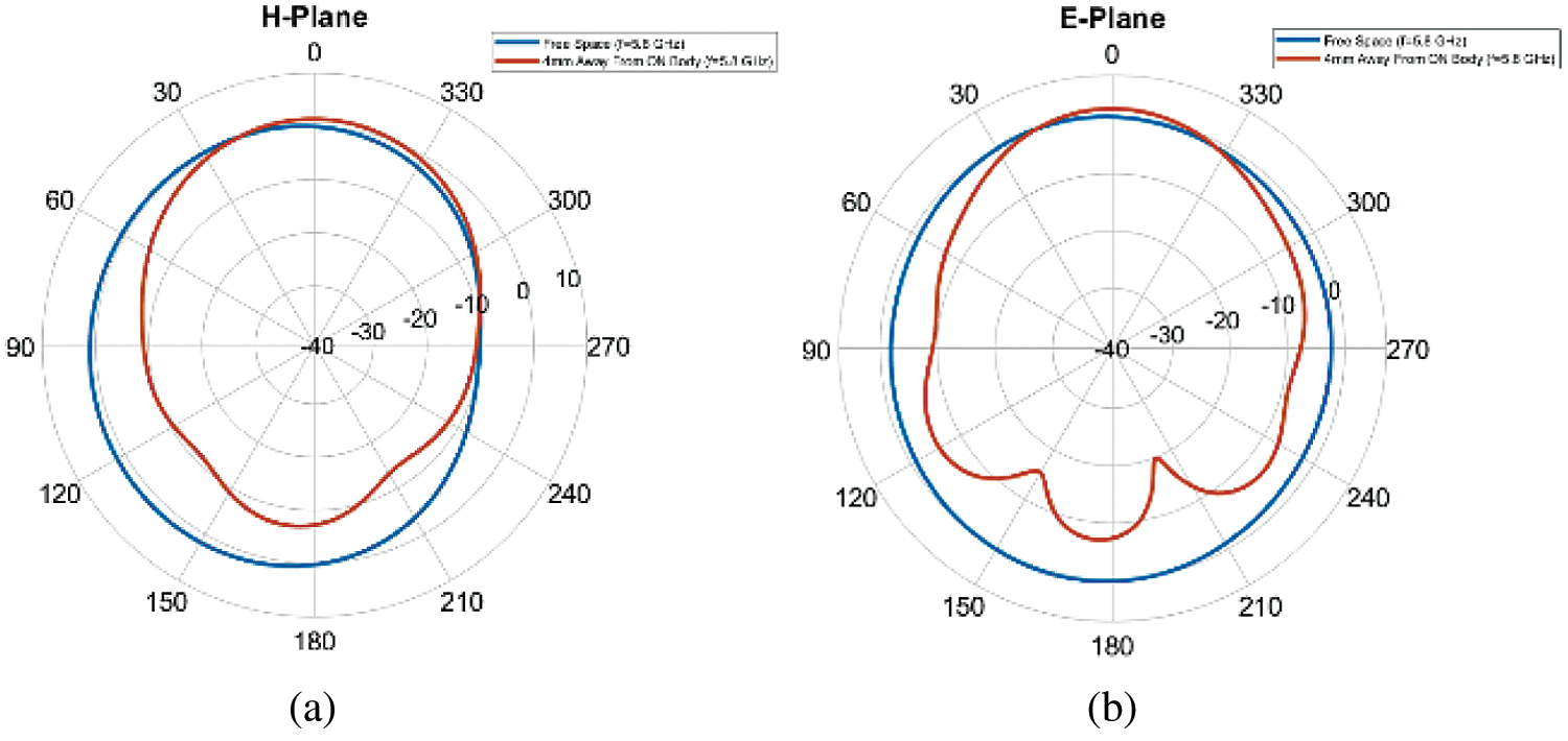
Figure 14: At 5.8 GHz, a comparison of radiation patterns: (a) On H-Plane; (b) On E-Plane
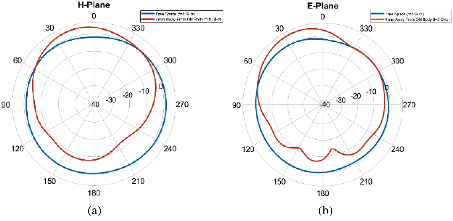
Figure 15: At 8 GHz, a comparison of radiation patterns: (a) On H-Plane; (b) On E-Plane
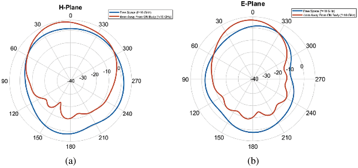
Figure 16: At 10 GHz, a comparison of radiation patterns: (a) On H-Plane; (b) On E-Plane
4.4 Radiation Efficiency Comparison
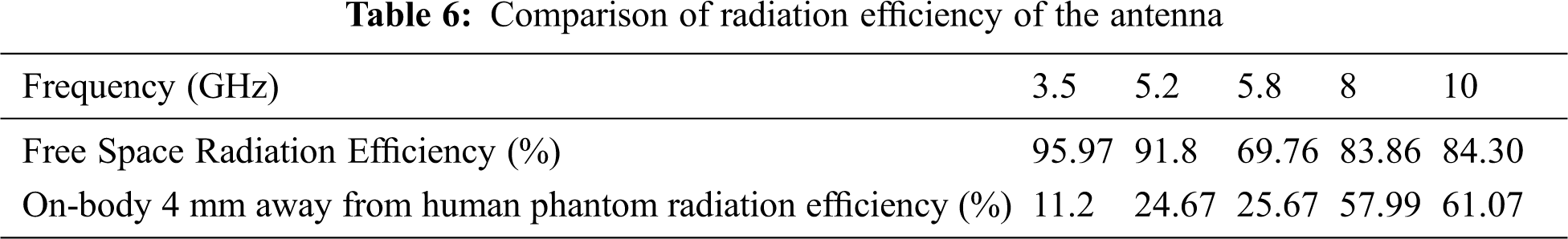
Antenna radiation efficiency on both 4 mm distance away from on-body and free space are simulated and compared at various frequencies. Tab. 6 listed the comparison of radiation efficiency of the antenna. Although the radiation efficiency on the body decreases, it remains within acceptable ranges. As the phantom body act as a lossy medium, the power absorbed by the phantom body tissues results in low radiation efficiency than free space. At 5.8 GHz, the antenna efficiency is poor, 69.76% at free space and 25.67% at on body. This indicates the effectiveness of band-notch characteristics. At 10 GHz, the antenna efficiency is high, 84.29% in free space and 61.07% at on-body. The on-body simulation studies are quite steady and comparable to free space at higher frequencies.
5 Distance Variation on Body Performance Parameter Study
To investigate the distance variation of on-body antenna performance, the antenna is simulated placing on a phantom body model consisting of skin, fat, and muscle layers.
5.1 Return Loss Comparison for Different Distances from the Body
The antenna was positioned at various distances from the phantom body model during on-body simulation. The designed antenna’s return loss curves for various gaps are shown in Fig. 17. When the antenna was replicated by positioning it at various distances from the phantom body model, the return loss curve changed slightly to the left. As the separation between the phantom body and the antenna grows, the performance improves. After the simulation in all distance cases, the band notch characteristics of the antenna remain the same, and they showed band notch behavior. Fig. 17 shows that improved return loss response occurs at distances of 4 mm, 6 mm, 8 mm, and 10 mm from the phantom body model. At 8 mm and 10 mm gaps, good impedance matching performance may be found.
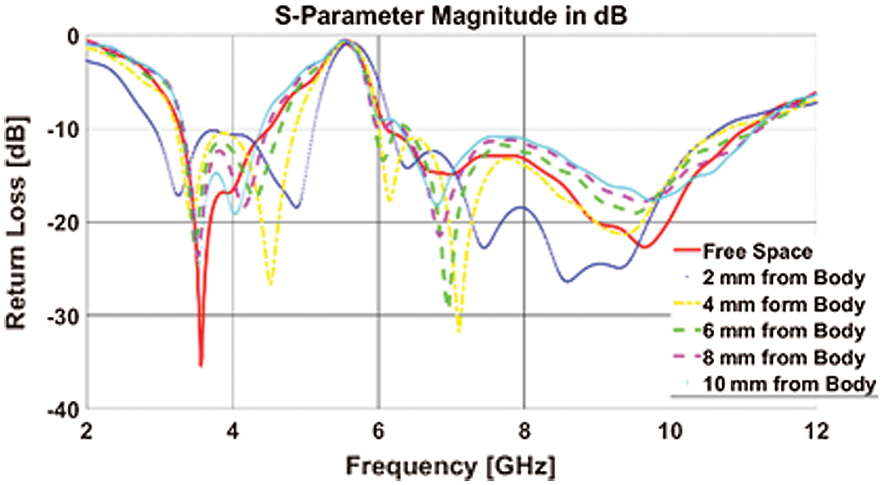
Figure 17: S-Parameter (return loss curves) comparison at different distances of antenna away from the body model, including free space return loss
5.2 Antenna Gain and Radiation Efficiency Comparison for Different Distances from the Body
Tab. 7 shows the comparison of antenna gain and radiation efficiency of the proposed antenna.
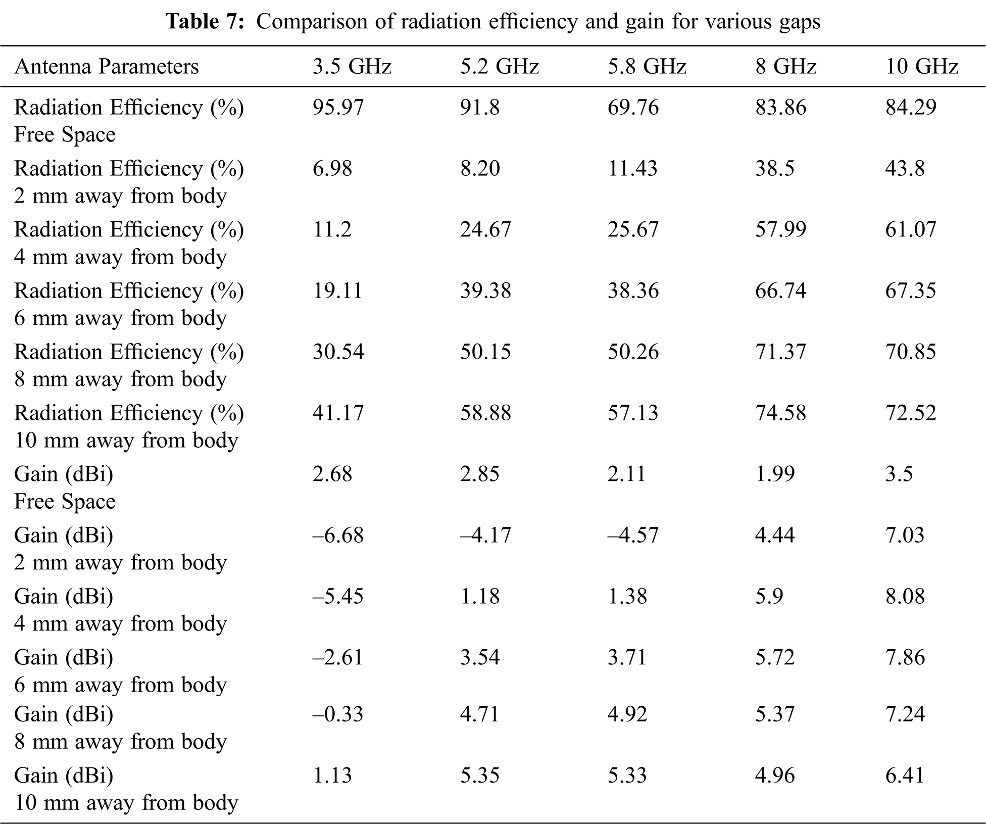
From Tab. 7, it is observed that the antenna shows better value when the gap between the proposed antenna and the phantom body model raises. Very poor gain is seen at the 3.5 GHz due to no transmission. Nevertheless, at 4 mm, 6 mm, 8 mm, and 10 mm distances, this antenna presents a better result. Because of the reflections and refraction involved in the phantom body model, the antenna’s radiation pattern alters when it is put on it. As a result, the antenna’s gain grows as the separation between it and the phantom body grows. For example, at 10 GHz, the designed antenna attained a good on-body gain of 8.089 dBi when kept at a 4 mm distance.
When the antenna is put on the phantom body, it absorbs power since it behaves as a lossy medium. As a result, during the on-body scenario, the radiation efficiency drops. The radiation efficiency of an on-body antenna improves as the separation grows. When the proposed antenna is placed 10 mm away from the phantom body model, it shows very good on-body radiation efficiency of 41.17%, 58.88%, 57.13%, 74.58%, and 72.52% for 3.5 GHz, 5.2 GHz, 5.8 GHz, 8 GHz, and 10 GHz respectively.
The impact of changing key factors like slot size and spacing on antenna performance were investigated in this study. The length of the slots was modified from 18.08 mm to 16.57 mm and 19.89 mm, respectively. The size of the ground plane was modified from 9 mm to 8.5 mm and 9.5 mm.
The Shawn-shaped antenna patch, substrate, and ground plane were preserved to the same dimensions as the previous section for slot lengths of 16.57 mm and 19.89 mm. Thus, only slot length was changed from 18.08 mm to 16.57 mm and 19.89 mm. Fig. 18 shows that the return loss curve’s band notch portion shifted to the left for slot length 19.89 mm and band notch portion shifted to the right for slot length 16.57 mm. The radiation efficiency was 94.41% (highest) at 3.5 GHz for 16.57 mm slot length and 94.57% (highest) 3.5 GHz for 19.89 mm slot length. The maximum gain achieved was 3.801 dB and 3.242 dB at 10 GHz for 16.57 mm and 19.89 mm slot length, respectively.
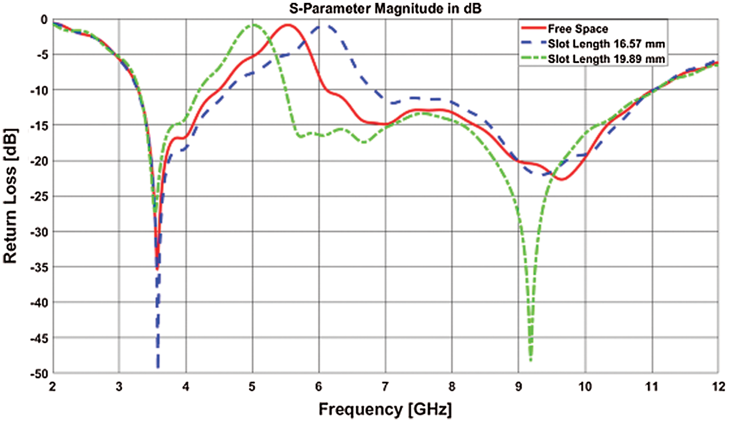
Figure 18: Return loss curve for different slot length
6.2 Variation of Ground Plane Length
The main antenna was maintained 9 mm ground plane length. A change of ground plane length to 8.5 mm causes the return loss curve to slightly left shift, and ground plane length 9.5 mm causes the return loss curve to a little bit right shift. Although, the notched frequency band remains within the desired range. Fig. 19 presents the return loss curve for the ground plane’s different lengths. The maximum gain of 3.115 dB and 3.773 dB was achieved at 10 GHz for 8.5 mm and 9.5 mm ground plane length. The maximum radiation efficiency was 93.70% for 9.5 mm ground plane length and 96.05% for 8.5 mm ground plane length.
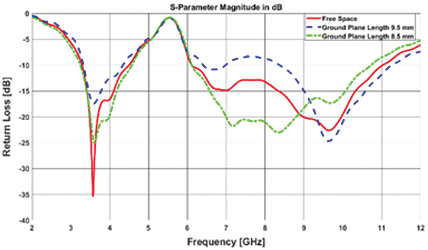
Figure 19: Return loss curves for different ground plane length
The major goal of this work is to build a new tiny UWB antenna for body-centric communication with band notched features. At different frequencies, the performance parameters of this UWB antenna were investigated in free space and on a 3-layer phantom body model at a close distance. The intended antenna is very compact in size and it has the ability to avoid the interference caused by some other existing network systems. The on-body results of the antenna are at an acceptable level for BCWCs. The results of the on-body antenna performance parameters and analysis revealed that the proposed antenna could be placed 4 mm away from the body to achieve the best results for power-efficient and inference-free communication. From on-body performance parameters, the proposed UWB band-notch antenna is less sensitive due to the effects of the phantom body model. So it can be said that due to its tiny size, novel shape, and significant on-body performance, the proposed antenna can serve practical working fields like medical applications and sports applications. Due to lack of scope, this study is based on simulation results. CST software provides very close results to measurement as found in the literature.
Acknowledgement: We would like to give special thanks to Taif University Researchers supporting project number (TURSP-2020/216), Taif University, Taif, Saudi Arabia.
Funding Statement: Taif University Researchers are supporting project number (TURSP-2020/216), Taif University, Taif, Saudi Arabia.
Conflicts of Interest: The authors declare that they have no conflicts of interest to report regarding the present study.
 | This work is licensed under a Creative Commons Attribution 4.0 International License, which permits unrestricted use, distribution, and reproduction in any medium, provided the original work is properly cited. |