Engineering & Sciences
| Computer Modeling in Engineering & Sciences |
DOI: 10.32604/cmes.2021.013568
ARTICLE
Remote Sensing Monitoring Method Based on BDS-Based Maritime Joint Positioning Model
1Hubei Key Laboratory of Inland Shipping Technology, School of Navigation, Wuhan University of Technology, Wuhan, 430063, China
2Donghai Navigation Safety Administration, Ministry of Transport of the People’s Republic of China, Shanghai, 201206, China
3Al-Nahrain Nanorenewable Energy Research Centre, Al-Nahrain University, Baghdad, Iraq
*Corresponding Authors: Osamah Ibrahim Khalaf. Email: usama.ibrahem@coie-nahrain.edu.iq; Zhao Liu. Email: haishiliuzhao@163.com
Received: 11 August 2020; Accepted: 22 December 2020
Abstract: Complicated sea conditions have a serious impact on ship navigation safety and even maritime accidents. Accordingly, this paper proposes a remote sensing monitoring method based on the Beidou Navigation Satellite System (BDS) maritime joint positioning model. This method is mainly based on the BDS and multiple Global Navigation Satellite Systems (GNSS) to build a data fusion model, which can capture more steady positioning, navigation, and timing (PNT) data. Compared with the current Global Positioning System (GPS) and Global Navigation Satellite System (GLONASS) mandatory used by the International Maritime Organization (IMO), this model has the characteristics of more accurate positioning data and stronger stability. The static and dynamic measurement show that such a model works for maritime ships and maritime engineering. Combined with the Ship’s Automatic Identification System (AIS) and Geographic Information System (GIS), a BDS-based remote sensing monitoring method can cover the world, serve maritime ships and construct maritime engineering.
Keywords: Ship navigation; AIS; BDS; GPS; data fusion
For ship navigation, Automatic Identification System (AIS) can provide continuous and steady positioning, navigation, and timing (PNT) data for ships and reduce maritime risks and maritime accidents. According to the technical requirements for shipborne terminal equipment proposed by the International Maritime Organization (IMO) and the International Association of Maritime Aids to Navigation and Lighthouse Authorities (IALA), global navigation ships must be equipped with GPS and Global Navigation Satellite System (GLONASS) to capture PNT data to serve on shipboard AIS terminal equipment. However, shipboard terminal equipment using GPS and GLONASS has the limitations of weak PNT data capture capability, poor signal quality, and susceptibility to interference and deception. Accordingly, this paper proposes a remote sensing monitoring method based on the BDS and GPS maritime joint positioning model as experiments show that Beidou Navigation Satellite System (BDS)/Global Positioning System (GPS) can improve the continuity and steady of PNT data fusion captured by maritime terminals. Also, the short message function of BDS can cover the whole world, and the combination of Geographic Information System (GIS) data is more helpful to improve the remote sensing monitoring ability of ships and maritime engineering.
Multi Global Navigation Satellite Systems (GNSS)-based positioning data processing methods are different, which include Standard Single Point Positioning (SPP), Precise Point Positioning (PPP), Real-Time Kinematic (RTK), and Differential Global Navigation Satellite System (DNGSS). These Different methods can obtain positioning data results with their unique accuracy and characteristics. Given that ship navigation requires positioning data with strong continuity and stability, which differs from the high precision actual requirements of engineering construction and unmanned vehicles, the joint positioning model based on BDS and GPS is suitable for ship navigation.
In the experimental design, remote sensing monitoring methods based on the BDS maritime joint positioning model are constructed, consisting of static measurement, dynamic measurement and visual verification based on GIS data fusion. There are three advantages as follows. Firstly, integration of BDS/GPS, the electronic chart display and information system (ECDIS) and AIS for enhancing the ability to capture PNTs data. Secondly, the method of combing the BDS global short message function can achieve global coverage and the ability to serve global ships and maritime engineering. Lastly, the remote sensing monitoring method based on the BDS maritime joint positioning model has the comprehensive service capabilities of global remote sensing monitoring, distress awareness and distress warning, which can meet many practical needs of maritime engineering.
Section 2 introduces related research work, and then the maritime joint positioning model and algorithm based on BDS/GPS are summarized in Section 3. Next, Section 4 introduces a framework of the maritime remote sensing monitoring system based on BDS/GPS. Its primary data fusion verification of ECDIS combined with GIS data. It needs to be verified that the remote sensing monitoring method based on the BDS maritime joint positioning model has comprehensive advantages of global coverage, data fusion and intelligent evaluation. Followed by Section 4, Section 5 elaborates the topic based on BDS, BDS/GPS, BDS/GPS/GIS in the Lujiazui Financial District, Pudong New District, in Shanghai. Lastly, Section 6 evaluates BDS, BDS/GPS, and BDS/GPS/GIS. Conclusions are presented in the final chapter.
Previous studies find that the remote sensing monitoring method based on the BDS maritime joint positioning model has obvious advantages over the various methods currently used, such as wide coverage, long-distance telemetry sensing, high data transmission efficiency and large-scale use.
Former studies also indicate that Researchers mostly use high-performance computers and deep learning-based target recognition methods to detect, identify and classify ships. For example, synthetic aperture radar monitoring is now used for ship navigation [1] and long coverage distances, ship detection and classification from satellite-borne optical images [2]. Besides, synthetic-aperture radar (SAR) systems are used to detect moving targets at sea and detect ship data streams [3–5]. In addition, using human-like ship identification methods, deep convolutional networks are used to detect ship targets [6–9]. Fishing boats are common ship targets in maritime navigation, but they are not easily recognized their small targets with weak radar echoes. Therefore, high-resolution image recognition methods are used to identify and classify small targets [10–12].
Researchers from various countries use Hybrid/Compact Dual-Pol SAR to process ship and oil spill data [13,14]. For example, deep convolutional networks and image recognition based on large scale image recognition are suitable for collecting dynamic navigation data and recognizing ships [15,16]. Also, as high high-performance computer technology has developed rapidly and iterated rapidly, updated recognition methods using new computational vision frameworks has also been proposed [17–19]. Canadian researchers have further proposed using network recognition methods to deal with target detection frameworks, which will be considered on ships in the future identification of ship data [20]. Besides the feature pyramid network recognition method has been used for object detection and unified real-time object detection. Moreover single-shot multi-box detectors, deformable convolutional networks, and single-shot object detectors based on multi-level feature pyramid networks are all correct target detection networks and can all propose new ideas for correct target detection [21–25]. Later on, a brand new identification method, using CNN, SAR ship detection multi-layer fusion method and high-density end to end neural network combined with SAR, is used to identify and classify ships [26–28].
Given the limitation of the computing capacity of computer Graphics Processing Unit (GPU) for ship recognition and classification, researchers also proposed an R-CNN image processing method with faster compression and excitation level and a deep neural network multi-scale which was based on the attention mechanism and the ship detection method under the scene [29,30]. In addition, the ship identification method based on the attention pyramid network and the automatic ship detection method combined with Google Earth remote sensing image in the complex scene are proposed [31,32].
However, there is a little corresponding basic research on shore-based control systems and maritime data transmission methods. In relation to this, Iraqi researchers proposed research based on the optimal location of wireless sensors and nodes [33] and an ultra-long-distance transmission method combined with block-chain application technology and the frequency estimation of minimum mean square error and P-value distribution in wireless sensor networks [34,35] which can be applied to maritime data transmission systems. Combined the current wireless data transmission method, Bee algorithm is further proposed to optimize the network coverage of wireless transmission and an improved wireless sensor network algorithm with enhanced lifespan [36,37] and intelligent communication transmission methods, intelligent IoT services and the performance and data analysis of machine type communication equipment in cellular networks, network cloud processing models and evaluation methods, and adaptive intelligent early warning methods for wireless sensor networks [38–40].
When the ship sails at sea, the energy-saving routing and reliable data transmission protocol and map matching algorithm in wireless sensor networks (WSN) can be adopted, while the intelligent application can also be used for real-time location tracking [41–43]. On the other hand, the use of wireless sensors to enhance ships’ position on the sea and the use of routing and protocols, combined with multi-GNSS and INS artificial intelligence technology, can improve the stability and reliability of ship positioning data transmission [44,45]. Moreover, providing real-time marine meteorological data to serve sailing ships will reduce maritime accidents [46].
China’s BDS has developed rapidly, and receiver performance has improved rapidly. Researchers proposed a low-cost and high-quality receiver RTK analysis and BDS/GPS kinematics positioning performance evaluation method [47–49]. The researchers also proposed a new method to evaluate receiver performance and research on GPS/INS navigation method with fast convergence in complex environments [50–52]. Therefore, the BDS-based maritime joint positioning method has the advantages of a data transmission system with ultra-long distance and global coverage.
This paper proposes research on the fusion method of multi-source heterogeneous navigation data under complex sea conditions. Relying on the relevant research foundation, a remote sensing monitoring method based on the BDS-based maritime joint positioning model is proposed, and the following research is carried out.
The remote sensing monitoring method based on the BDS maritime joint positioning model is shown in Fig. 1. The BDS-based maritime joint positioning model and algorithm are as follows.
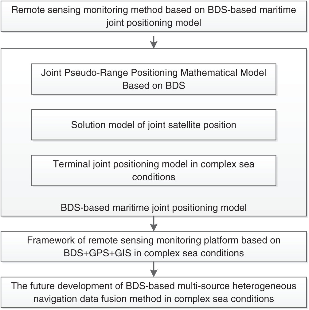
Figure 1: Methodology
3.1 Joint Pseudo-Range Positioning Mathematical Model Based on BDS
Assuming that the nth satellite (BDS satellite or GPS satellite) is observed by the BDS/GPS joint receiver m, the corresponding pseudo-range observation equation can be written as:
Among them,
In general, the last three terms of (1) have been compensated, and the above formula is simplified to:
The WGS 84 coordinate system of GPS and the CGCS 2000 coordinate system of BDS belong to the geocentric coordinate system. The definition methods of the two are the same, and the implementation method is the same. The CGCS 2000 coordinate system is the same.
Let
3.2 Joint Satellite Solution Model
Assuming that the time and space of the two systems are unified, Formula (2) is rewritten as:
where, k represents the type of satellite system, and i represents the i-th satellite observed under the system. Let
The Formula (5) is combined with Taylor expansion at
Among them:
Rewrite Formula (6) as a matrix formula as:
3.3 Maritime Terminal Joint Positioning Model
Furthermore, the BDS/GPS joint positioning equation can be obtained as:
Namely:
Among them: The first m is BDS satellites, the last n are GPS satellites,
4 The Framework of Maritime Remote Sensing Data Monitoring Platform
The maritime remote sensing data monitoring platform’s framework consists of a maritime terminal, a data transmission system, a shore-based monitoring system, and a GIS data fusion visualization system. The basic framework is shown in Fig. 2.
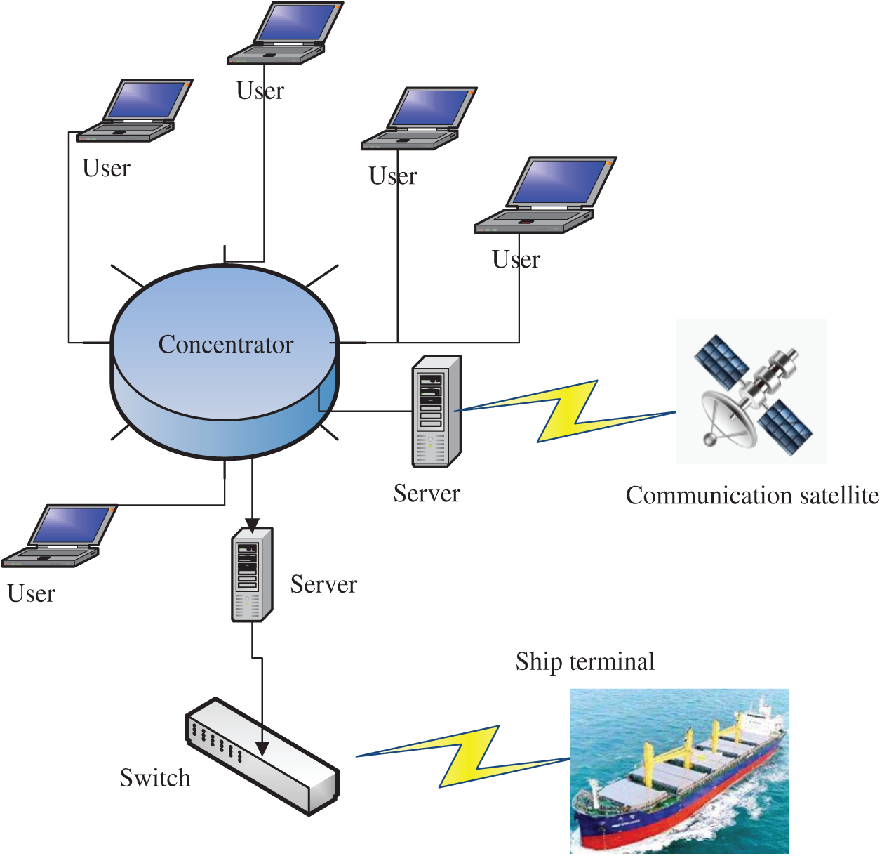
Figure 2: The framework of offshore remote sensing data monitoring platform
Offshore terminals can be installed on ships and maritime projects and can receive and send real-time navigation data. Data types include ship call sign, latitude position, longitude position, sailing speed, sailing direction and other data. The functions are as follows:
Communication function: The maritime terminal can be integrated into the computer of the ship and maritime engineering, and has the functions of data editing, storage and transmission.
Positioning function: The maritime terminal can integrate multi-system and multi-source heterogeneous navigation data. Such as BDS, GPS, GLONASS, etc., can be used for rapid joint positioning.
Early warning function: When ships and maritime engineering suddenly encounter extreme weather conditions, it has the function of early warning visualization.
The BDS-based radio deterministic satellite service (RDSS) communication positioning system covering the world can perform three major functions, positioning, message data transmission and instant messaging. It means that this system provides necessary, accurate and stable data transmission channels for ships sailing around the world.
Multi-source heterogeneous navigation data fusion in complex sea conditions requires multi-system compatibility, self-adaptation, short messages and other data transmission methods, and has a data fusion function. Therefore, a set of multi-system, multi-source heterogeneous navigation data fusion transmission method suitable for complex sea conditions is constructed. Take the communication system of TCP combined with IP control adopted by the ship as an example. The data transmission system consists of a data source port, host IP address and port. The target port is mainly used to identify and send data. Usually, when TCP sends data for the first time, the sequence number is 1 byte. Confirm that the serial number is used for the receiver’s next byte. Each time data is received, the confirmation sequence number increases by 1. Header length, the header length of TCP is 32 bytes in length, as shown in Fig. 3.
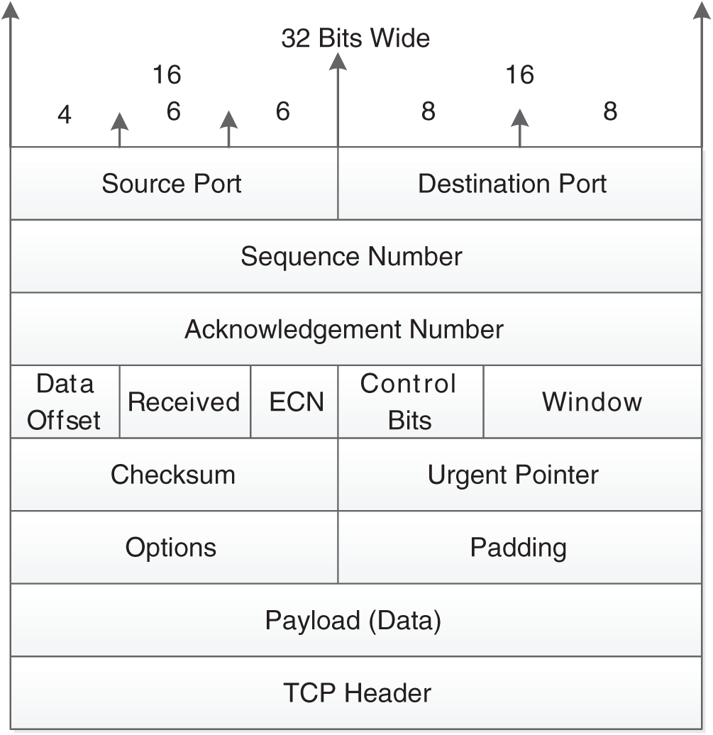
Figure 3: Communication protocol framework
4.3 Shore-Based Monitoring System
The maritime network under complex sea conditions can be connected to the special maritime dedicated server of BDS, and the confidential service agreement forms a complete data system. Therefore, a remote sensing monitoring system with multi-source heterogeneous navigation data fusion under complex sea conditions has been constructed. The system includes a ship navigation database server, maritime geographic database server, a wide area network (WAN) server, etc. The system hardware is composed of high-performance computers based on parallel and distributed. The software uses the deep learning algorithm of artificial intelligence technology to process, analyze, evaluate and predict massive data.
4.4 Visualization System Integrating GIS Data
A visual evaluation system integrates GIS data, using Python to build a visual evaluation system for remote sensing monitoring of multi-source heterogeneous navigation data based on BDS under complex sea conditions. The system is compatible with various navigation data such as AIS and ECDIS. Based on time-space transformation parameters, it can intelligently provide historical, real-time and predicted navigation data and evaluate and visualize it.
The place of experiment is located in Lujiazui Financial Service Zone, Pudong New Area, Shanghai. There are many tall buildings in this area, and the number and density of buildings over 300 m high are the highest in the world. Adjacent to Lujiazui, Huangpu River is a typical scene of ships sailing through narrow waterways. However, multipath interference influences these waterways., The area with the highest density of buildings with complex environments, strong interference and strong typicality, and complex scenes such as narrow waterways and multipath interference, is typical. Accordingly, static measurement and dynamic measurement experiments are carried out in this area.
The research area is located in Lujiazui Financial District, Pudong New District, Shanghai, as shown in Fig. 4.
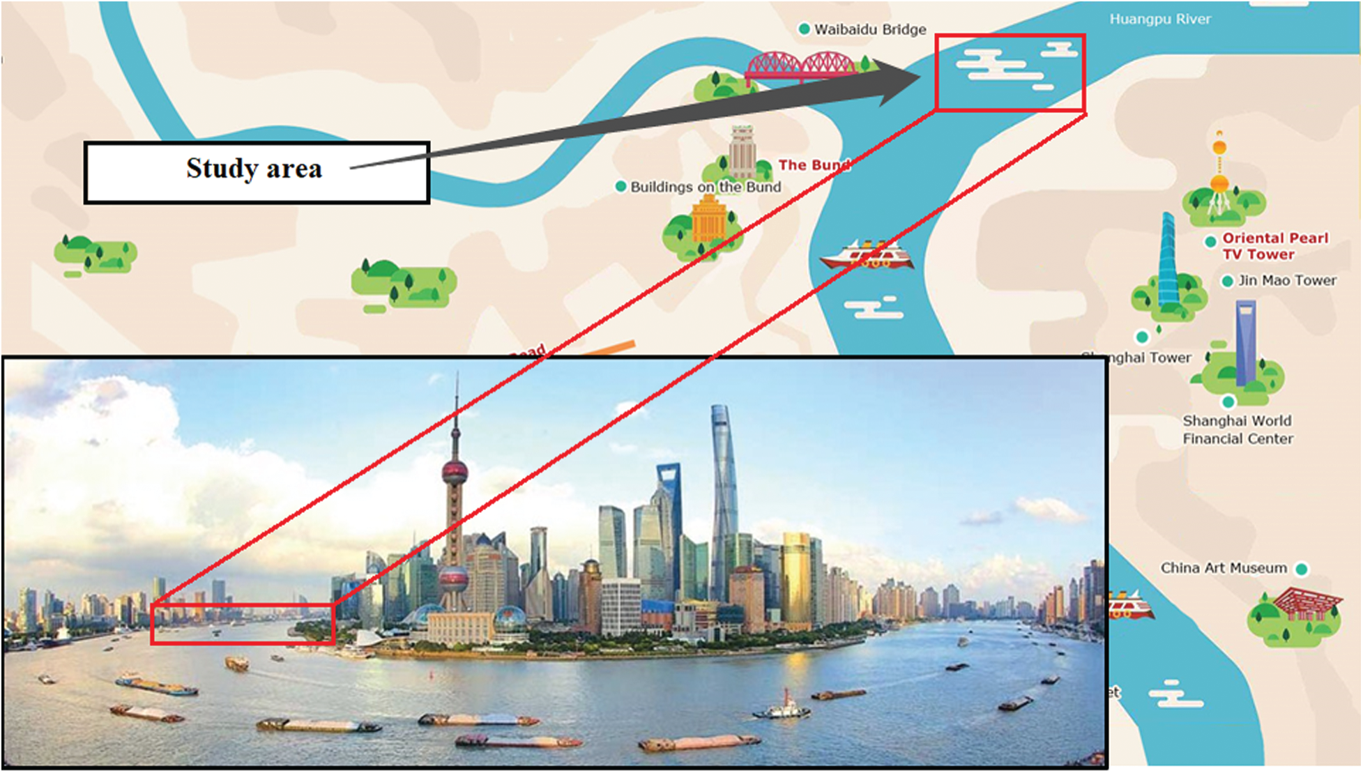
Figure 4: Study area
The measurement experiment includes two measurement methods: static measurement and dynamic measurement. In addition, the remote sensing method based on the BDS maritime joint positioning model is used to conduct experiments to explore the possibility of providing remote sensing monitoring, perception and prediction evaluation based on artificial intelligence technology for global maritime ships and maritime projects.
Target determination, static positioning measurement and dynamic positioning measurement, and verification of remote sensing monitoring and evaluation methods are all based on GIS maritime joint positioning model.
Measuring equipment and receivers are produced by BDStar Navigation Co., Ltd., Beijing, China.
The U star observation software version 2.1.0 developed by BDStar Navigation Co., Ltd., Beijing, China is used to record the observation data.
The positioning data evaluation software RTKLIB version 2.4.3 is used to evaluate the observation results.
The measurement results are static measurement and dynamic measurement, respectively. In static measurement, the steady of PNT data is better than BDS after comparing BDS/GPS. For dynamic measurement, the continuity, usability and steady of PNT data after comparing BDS/GPS are better than BDS. The fusion of remote sensing monitoring, perception and prediction based on artificial intelligence technology combined with GIS has global coverage function.
As shown in Fig. 5, static measurement is located at Lujiazui Metropolitan Yacht Club, Pudong New District, Shanghai, China. The test time is 60 min, the sampling interval is 1 s, and the result of obtaining PNT data based on BDS is marked in red. The measurement results show that multiple coupling factors lead to the capture of BDS-based irregular PNT data, as shown in Fig. 6.
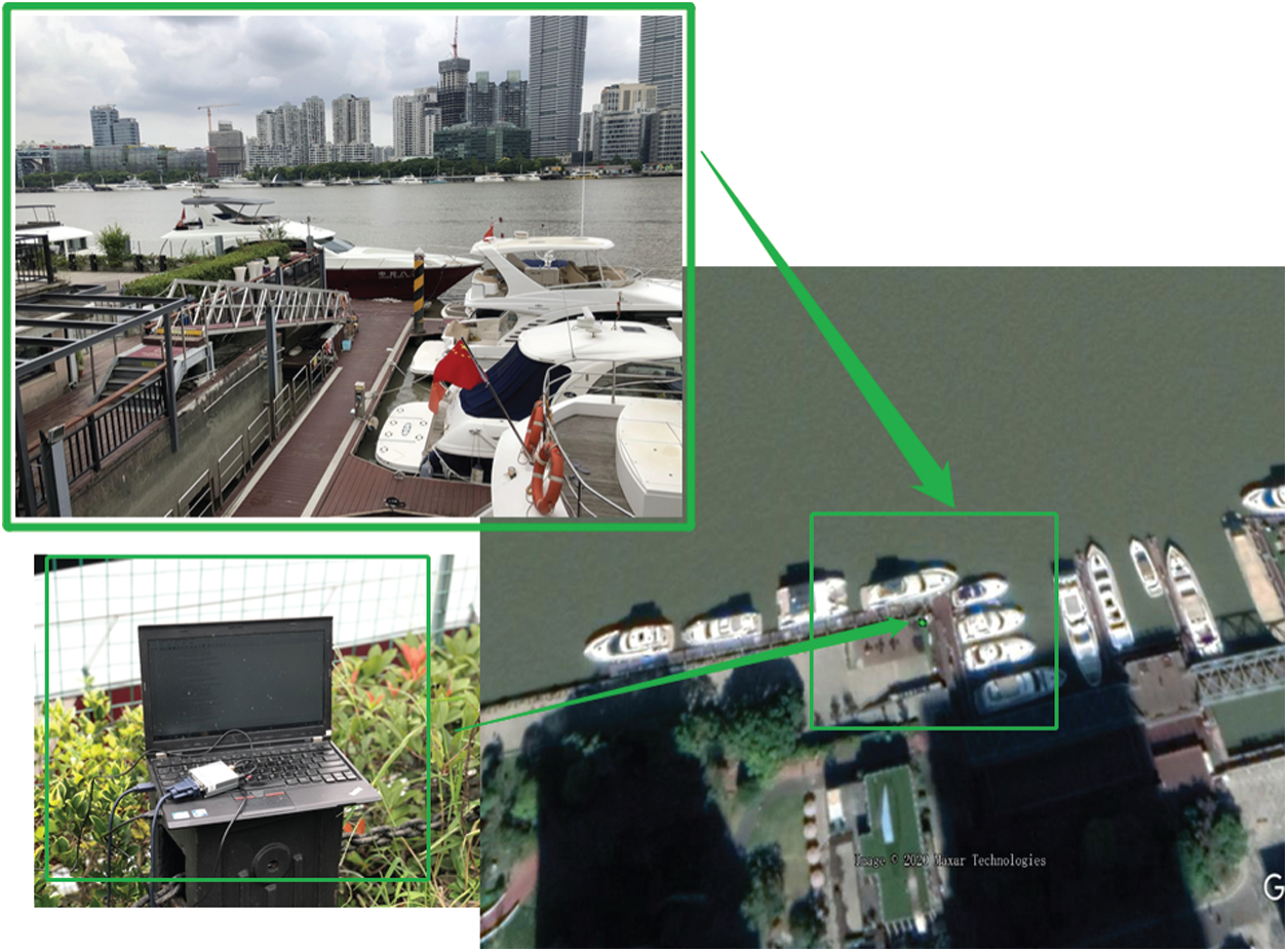
Figure 5: Static measurement
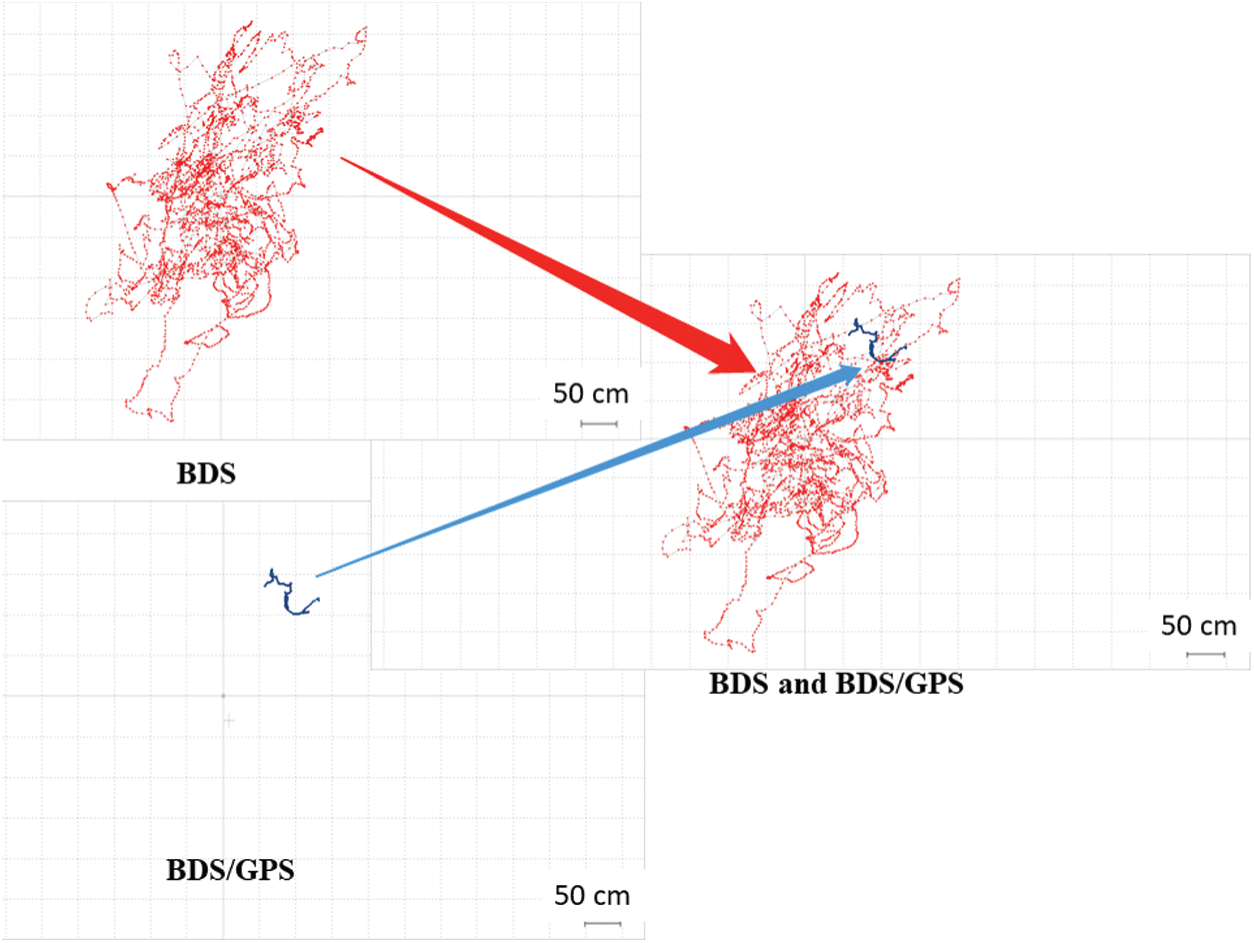
Figure 6: Static measurement
PNT data is captured based on BDS/GPS and marked in blue, as shown in Fig. 6. The statically measured east, south, and upward distance parameters are visible. If only BDS is used as the method of capturing PNT data. The positioning results show that the errors in the east, south, and upward directions are relatively large. BDS/GPS captured PNT data fusion results show that BDS/GPS can improve the static positioning accuracy by about 68%.
As shown in Fig. 7, the BDS static measurement, continuous observation for 60 min, the number of observation satellites is 6. Using BDS/GPS joint measurement, the number of available satellites is 19–21. When using BDS/GPS joint observation, the receiver can capture more PNT data. At the same time, the receiver’s solution capability is fully released. The observation results show that the PNT data has the characteristics of strong continuity, reliability and stability. owing to the number of satellites which can capture PNT data has increased from 6 to 21 after the receiver is integrated with GPS.
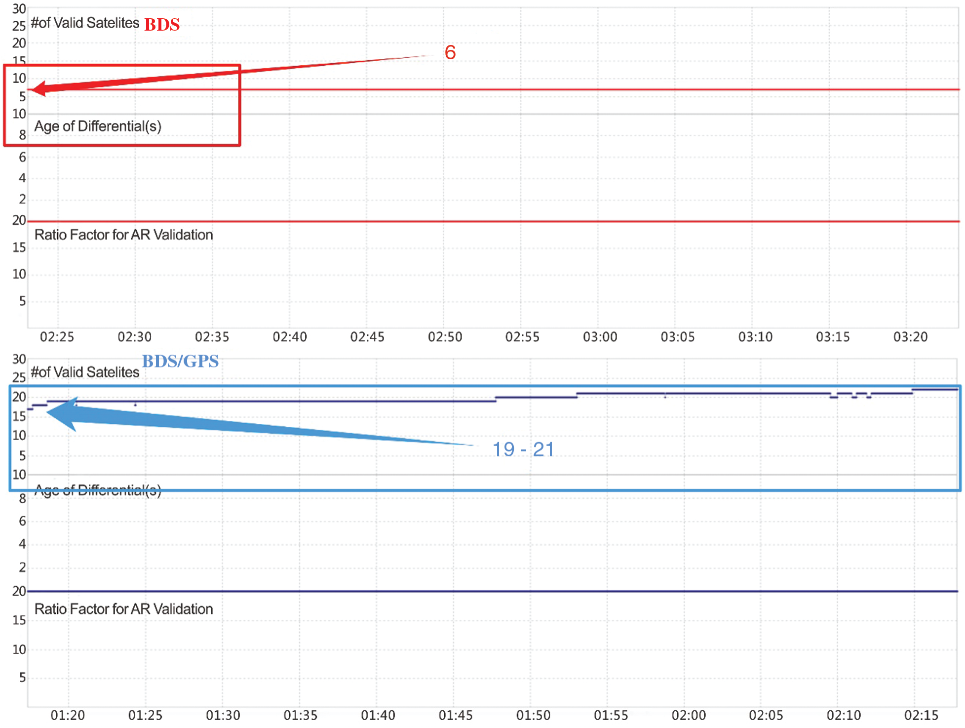
Figure 7: Number of satellites that can be observed
As shown in Fig. 8, after adopting BDS/GPS, the receiver can capture more PNT data, which effectively improves the solution accuracy and shortens the solution time. At the same time, accurate calculation data of longitude, latitude and elevation are obtained. Therefore, when BDS/GPS solves PNT data at sea, the solution results have the characteristics of fast convergence, high accuracy and strong reliability.
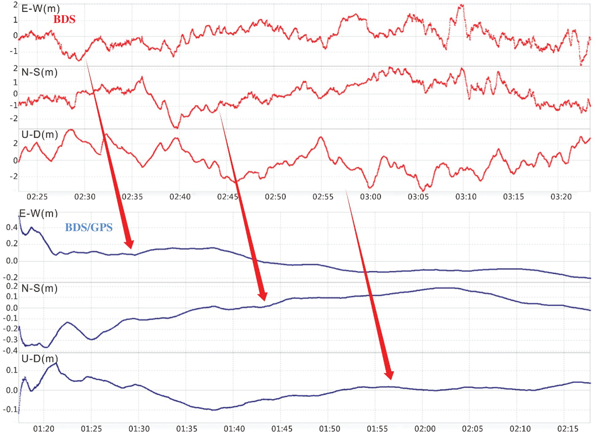
Figure 8: Performance advantages based on the BDS maritime joint positioning model
Dynamic measurement, located at Qichangzhan Ferry in Lujiazui Financial Service Zone, Pudong New District, Shanghai, China. The ship crossing narrow waterways is used as the measurement method for specific scenarios. In order to better capture the fusion results of PNT data and show the characteristics of the convergence of the positioning data, the experiment was carried out using the BDS/GPS joint measurement method, which was marked in blue. Ships sailing in specific scenes with high ship flow density, using the navigation method of crossing narrow waterways, and using the BDS/GPS combined dynamic measurement method.
The measurement results show that when the ship traverses a narrow channel, the ship’s navigation direction is affected by factors such as water velocity, water flow direction, wind force, and wind direction in the experimental area. Ship pilots need to change the ship’s power output and adjust the course based on ship driving’s long-term accumulated experience. Therefore, when a ship navigates through narrow waters and specific waters with high ship flow density, ship drivers need to drive carefully and manipulate the ship based on experience, as shown in Fig. 9.
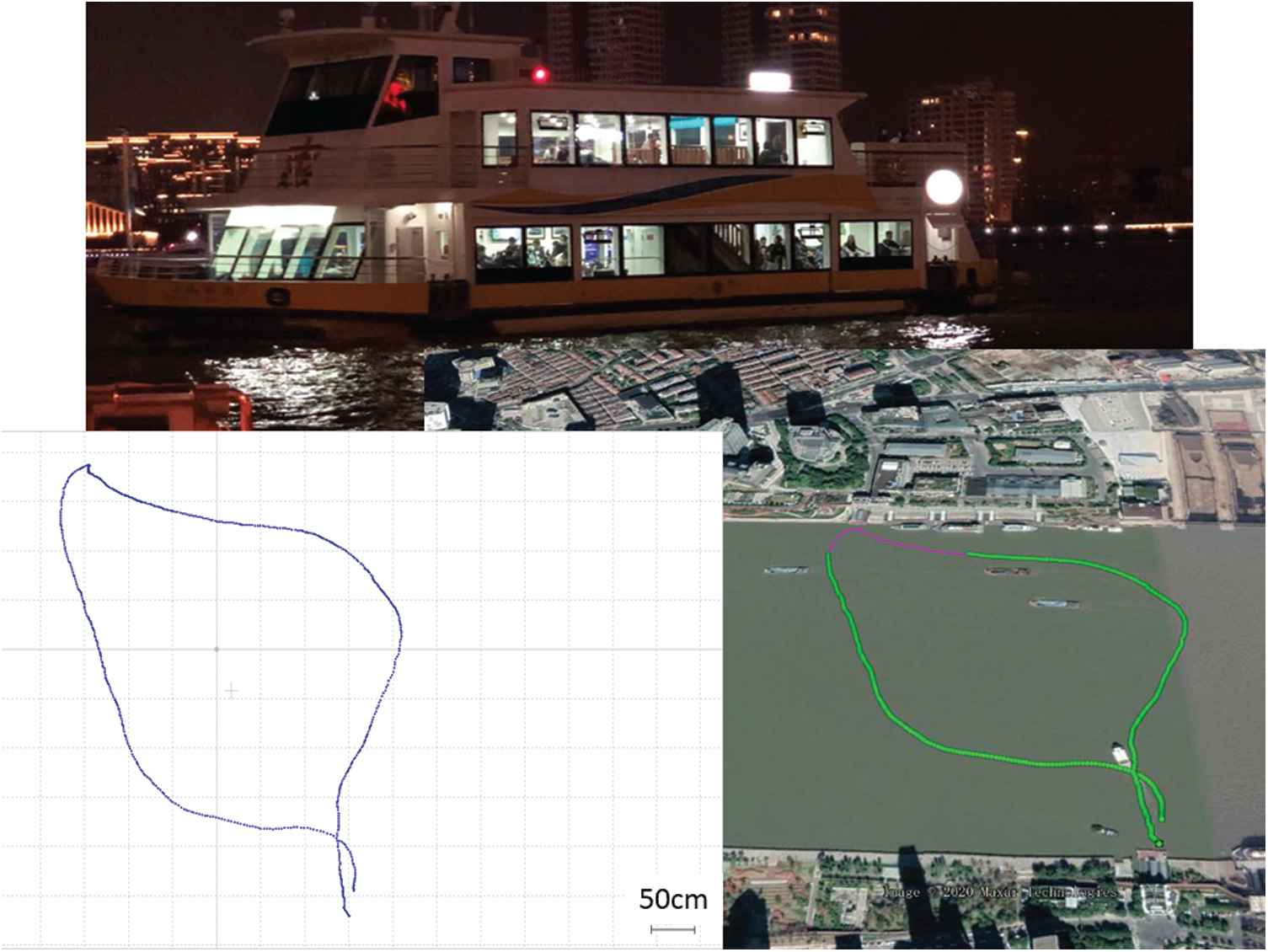
Figure 9: Dynamic measurement
It can be seen that the remote sensing monitoring method based on the BDS/GPS maritime joint positioning model can provide ships and maritime engineering with intelligent perception evaluation results with high positioning accuracy, fast positioning speed, and strong data fusion steady.
6.3 Visualization of BDS Combined GPS and GIS Data Fusion
The multi-source heterogeneous navigation data fusion method under complex sea conditions uses the PNT data after the fusion of BDS and GPS to display on the GIS. Similarly, the multi-source heterogeneous navigation data fused with AIS can achieve the same visualization effect. Data based on ECDIS is fused for data fusion and visual display, as shown in Fig. 10.
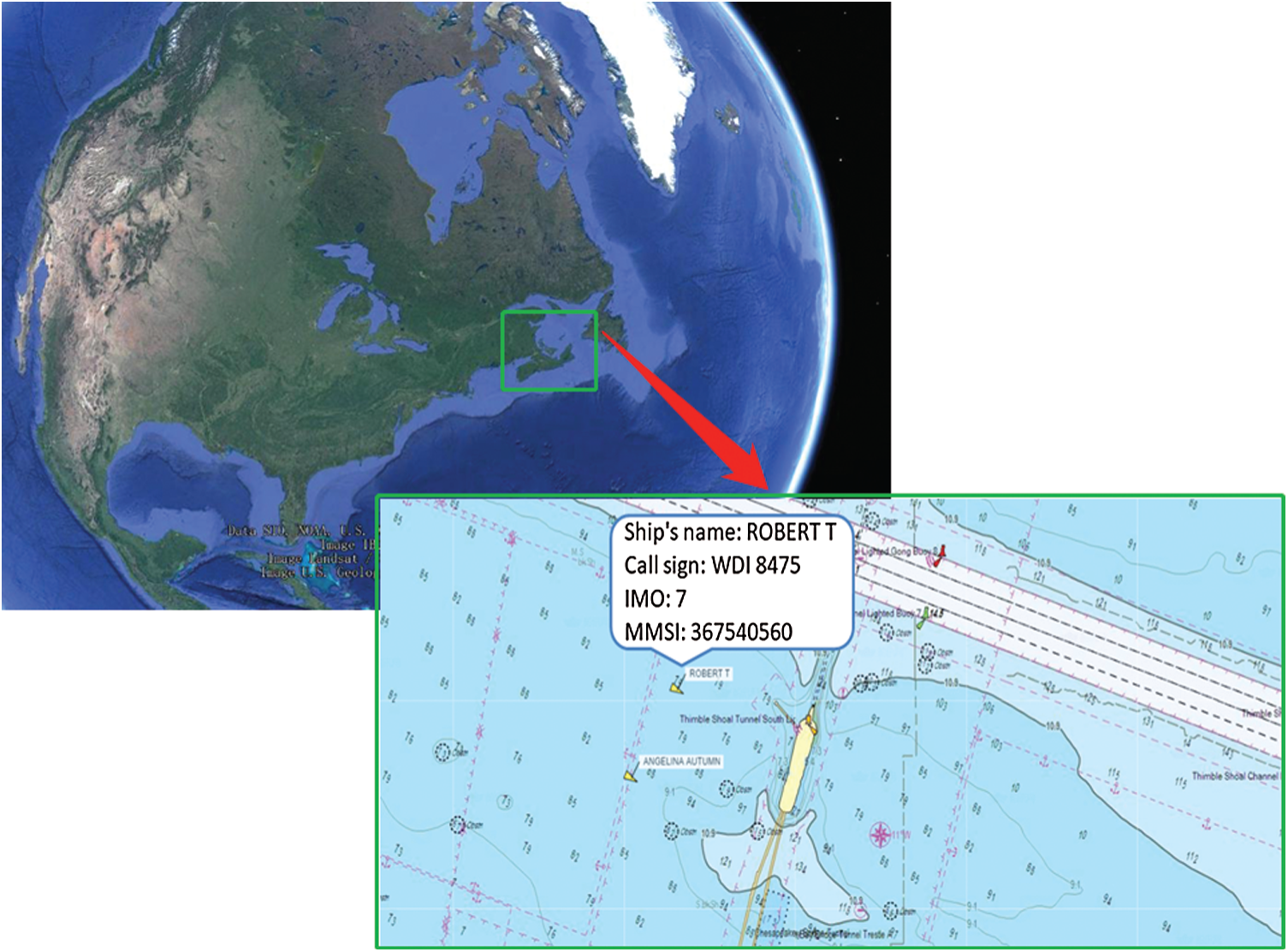
Figure 10: Visualization effect of BDS-based maritime support data fusion
The ship data fusion based on the ECDIS and the Ship’s AIS is displayed clearly in Fig. 10, such as the name of the ship is ROBERT T, the call sign of the ship is WDI 8475, IMO is 7, and Maritime Mobile Service Identify (MMSI) is 367540560. The BDS-based maritime joint positioning model and remote sensing monitoring method can be used to monitor ships and maritime engineering remotely. The brand new model can be used to monitor multi-source heterogeneous navigation data under complex sea conditions around the world, which is beneficial to reduce maritime accidents and maritime risks. The Electronic Navigation Chart (ENC) based on the S-57 standard is an ECDIS standard jointly developed by the International Maritime Organization (IMO), International Hydrographic Organization (IHO), and International Electrician Council (IEC). The S-57 standard is designed to convert and transmit digital hydrological data, such as object mark classification. Also, it is a legally effective data exchange and transmission standard for vectorized electronic navigation charts. Based on the results of ship positioning data combined with BDS and GPS and GIS with the S-57 standard format, real-time monitoring of global ships can be carried out.
Firstly, a remote sensing monitoring method based on the BDS maritime joint positioning model is proposed. Secondly, propose a maritime joint positioning model based on BDS/GPS. Thirdly, build a framework for maritime remote sensing monitoring platform based on BDS/GPS and carry out visual verification of static measurement and dynamic measurement combined with GIS data fusion. Fourthly, evaluate the measurement results of BDS, BDS/GPS and BDS/GPS/GIS. Finally, the conclusion shows that the remote sensing monitoring method based on the BDS/GPS maritime joint positioning model has the characteristics of global coverage, fast, reliable, stable and continuous, and can serve ships and maritime engineering.
This study proposed a remote sensing monitoring method based on the BDS maritime joint positioning model. In the future, it can promote the internationalization of BDS-based maritime terminals and submit them to international intergovernmental organizations such as IMO and IALA.
The static measurement results show that the static PNT data based on BDS has strong continuity and is suitable for ships and maritime engineering. Similarly, the data fusion result based on BDS/GPS maritime joint positioning has more significant advantages than BDS in all aspects. The dynamic measurement results show that the remote sensing monitoring method based on the BDS/GPS maritime joint positioning model has the advantages of continuous, steady and reliable under exposure scenarios. Using BDS/GPS PNT fusion data, more steady PNT data can be obtained. Therefore, it can provide steady data support for ships and maritime engineering worldwide.
Thirdly, the remote sensing monitoring method based on the BDS maritime joint positioning model. It adopts the BDS-based maritime joint positioning model and GIS data fusion. It can provide remote sensing monitoring services of multi-system, multi-source heterogeneous navigation data fusion under complex sea conditions for the world.
Fourthly, the receivers used by maritime administrations, shipping companies, and defense and naval departments worldwide mostly capture GPS and GLONASS’s PNT data as a navigation method for ship navigation. The remote sensing monitoring method based on the BDS maritime joint positioning model can improve stable obtaining PNT data under complicated sea conditions. In the future, China will deploy more satellites in low, medium and high orbits. By then, all vehicles’ steady performance and functional performance in the exposed space to obtain PNT data will be improved to a greater extent. Similarly, the actual demand for multi-source heterogeneous voyage data fusion based on BDS combined with GPS and GIS will be released in large quantities, and there will be a higher demand for brand-new maritime support infrastructure.
In the next step, new autonomous navigation sensors and models such as inertial navigation system (INS) and lidar will be combined to build a smarter and more efficient autonomous navigation method, which will serve the fusion of multi-source heterogeneous navigation data under complex sea conditions for ships and maritime engineering.
Recently, IMO has proposed using the remote sensing monitoring method based on the BDS maritime joint positioning model as a ship sailing in a narrow waterway to provide the necessary PNT data for determination. This paper’s research conclusions can be used as PNT data support to improve the BDS shipborne receiver’s performance to meet IMO and IALA’s recommended standards. At the same time, we will sort out the relevant measurement conclusions, form a draft proposal and push it to IMO and IALA, as a critical support carrier for the internationalization of BDS and China’s transportation power.
Funding Statement: This work was partially supported by National Natural Science Foundation of China under Grant No. 51809207, the National key research and development plan under Grant No. 2018YFC1407404, and the Fundamental Research Funds for the Central Universities (Nos. 2018IVA015, 2019IVB040).
Conflicts of Interest: The authors declare that they have no conflicts of interest to report regarding the present study.
 | This work is licensed under a Creative Commons Attribution 4.0 International License, which permits unrestricted use, distribution, and reproduction in any medium, provided the original work is properly cited. |