DOI:10.32604/cmc.2022.021237
| Computers, Materials & Continua DOI:10.32604/cmc.2022.021237 | |
| Article |
Cluster-Based Stable BSM Dissemination System for Safe Autonomous Platooning
School of Computer Science and Engineering, Chung-Ang University, Dongjak-gu, Seoul, 06974, Korea
*Corresponding Author: Sangoh Park. Email: sopark@cau.ac.kr
Received: 28 June 2021; Accepted: 30 August 2021
Abstract: Recently, the importance of vehicle safety supporting system has been highlighted as autonomous driving and platooning has attracted the researchers. To ensure driving safety, each vehicle must broadcast a basic safety message (BSM) every 100 ms. However, stable BSM exchange is difficult because of the changing environment and limited bandwidth of vehicular wireless communication. The increasing number of vehicles on the road increases the competition to access wireless networks for BSM exchange; this increases the packet collision rate. An increased packet collision rate impairs the transmission and reception of BSM information, which can easily cause a traffic accident. We propose a solution, the vehicular safety support system (V3S), which exchanges BSMs reliably even when many vehicles are on the road. The V3S uses a clustering scheme to decrease network traffic by reducing the amount of data exchanged between a vehicle and the roadside unit (RSU). In addition, the V3S reduces the collision rate of wireless network packets by broadcasting the vehicle's BSM in an allocated timeslot using the time division multiple access (TDMA) MAC protocol. The V3S also deals with insufficient bandwidth for dedicated short-range communications (DSRC) by changing DSRC channels according to traffic flow. In evaluating the packet error rate for stable BSM packet delivery, the V3S demonstrates an excellent packet error rate of less than 1%, compared to the 802.11p with its packet error rate of 82%.
Keywords: Road vehicles; communication systems; clustering methods; vehicular networks; basic safety message; dedicated short-range communication
With the continuing need for a more capable transportation environment, the intelligent transportation system (ITS) has emerged to provide the information needed for traffic management and vehicular safety [1]. The ITS has many traffic-related applications, but those related to safety, in particular, receive most of the attention because of ITS's connection with preventing property damage, injury, and death. Several autonomous driving technologies are being studied, and their safety aspects are most important. For safe driving, vehicles must periodically broadcast safety messages and exchange information. The wireless access in vehicular environment (WAVE) standard recommends that each vehicle broadcast a basic safety message (BSM) [2] at least once every 100 ms. The BSM is a safety message for sharing the vehicle's location, speed, and direction with nearby vehicles.
Communication between vehicles is central to exchanging BSMs reliably, and the vehicular ad-hoc network (VANET) technology supports this. VANET is a type of mobile ad-hoc network (MANET) that provides vehicle-to-vehicle (V2V) communications and vehicle-to-infrastructure (V2I) exchange. In addition, VANET supports many traffic-related applications for safety, entertainment, and vehicle traffic optimization [3–5].
The US Federal Communication Commission (FCC) has allocated a 75 MHz radio band to dedicated short-range communication (DSRC) at 5.9 GHz to support V2V and V2I communications [6]. DSRC provides high-speed wireless packet switching between vehicles and is utilized to provide ITS services. DSRC consists of one control channel (CCH) and six service channels (SCH), which are 10 MHz wide, as shown in Fig. 1. The use of the seven allocated channels determines the efficiency of DSRC bandwidth use. The CCH and SCHs have a fixed size, but studies have been made adjusting the CCH and SCH periods according to the vehicle communication environment [7–9] (e.g., extending SCH interval on low utilization of CCH [7]). Adjusting the CCH and SCH periods dynamically improves channel utilization by increasing the period of a channel that requires more bandwidth. This, in turn, allows more deliverable packets to be transmitted. However, the network topology changes rapidly because of the vehicle's high mobility. Even if the channel period is adjusted, topology changes cause the channel to need frequent adjustments to compensate [10]. Moreover, it is difficult to guarantee the communication delay time required to transmit the safety application message because the period of the channel is continually changing.
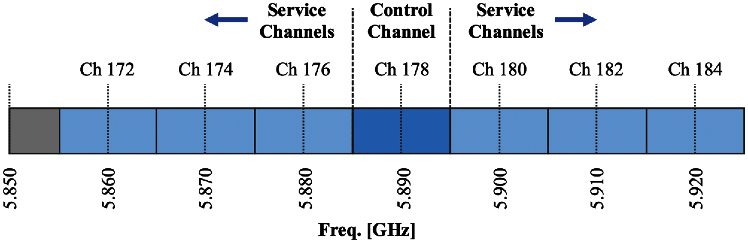
Figure 1: Spectrum allocation map of DSRC
This paper proposes a novel clustering-based vehicular safety support system (V3S) that reliably sends a BSM every 100 ms. The V3S has a cluster header that aggregates and transmits vehicle messages. The V3S solves the broadcast storm problem, which saturates a network by continuously broadcasting messages. In addition, the V3S eliminates the interference between channels by allocating one of the six SCH channels to each cluster with equal inter-channel distances. As a result, the V3S manages the hidden node problem, in which a data collision occurs while a node is communicating with an access point (AP) and another node tries to communicate with the same AP, ignorant of the first point's use of the AP. The V3S provides a stable communication environment even when the number of vehicles in the cluster increases, using the TDMA MAC protocol to communicate between clusters. Furthermore, the V3S removes channel interference between channels the same way and doubles the channel utilization on a bidirectional road environment, by interchanging an SCH-CCH channels according to the traffic direction. V3S is designed as an integrated architecture; vehicle module is activated for vehicles and RSU module is activated for RSUs. With alleviated data communication collisions, the V3S can reduce the communication delay and support reliable communication in a large number of vehicles environment.
The structure of this paper is as follows. Section 2 discusses related works that improve communications in the VANET environment. Section 3 proposes the V3S to support safety applications. Section 4 shows the results of our performance evaluation to validate that the V3S can transmit a BSM every 100 ms reliably. Finally, Section 5 reports our conclusions and future studies.
The BSM is a safety message used to establish a safe traffic environment according to the J2735 DSRC message set standards, published by the Society of Automotive Engineers. A BSM consists of two parts. Part 1 provides vehicle operating information such as location, speed, and direction. Part 2 provides optional data, such as weather, vehicle model, and user-defined information. Vehicles must send and receive BSMs to maintain safety applications; the WAVE standard recommends sending and receiving a BSM every 100 ms. The exchange establishes a communication environment to meet this requirement. Some factors must be considered, such as the DSRC period, communication bandwidth, and packet collisions.
As Fig. 2 shows, DSRC consists of one CCH channel and six SCH channels. The CCH is used to send high-priority safety messages or control messages, while the SCHs carry non-safety messages. One DSRC cycle consists of a 50 ms CCH period and a 50 ms SCH period. There is also a 4 ms guard time for channel switch. The channel design is crucial because transmission efficiency can increase depending on how the channels are utilized. If the periods of the CCH and the SCH are adjusted dynamically, the period of a channel that needs more bandwidths can be extended to increase channel utilization.
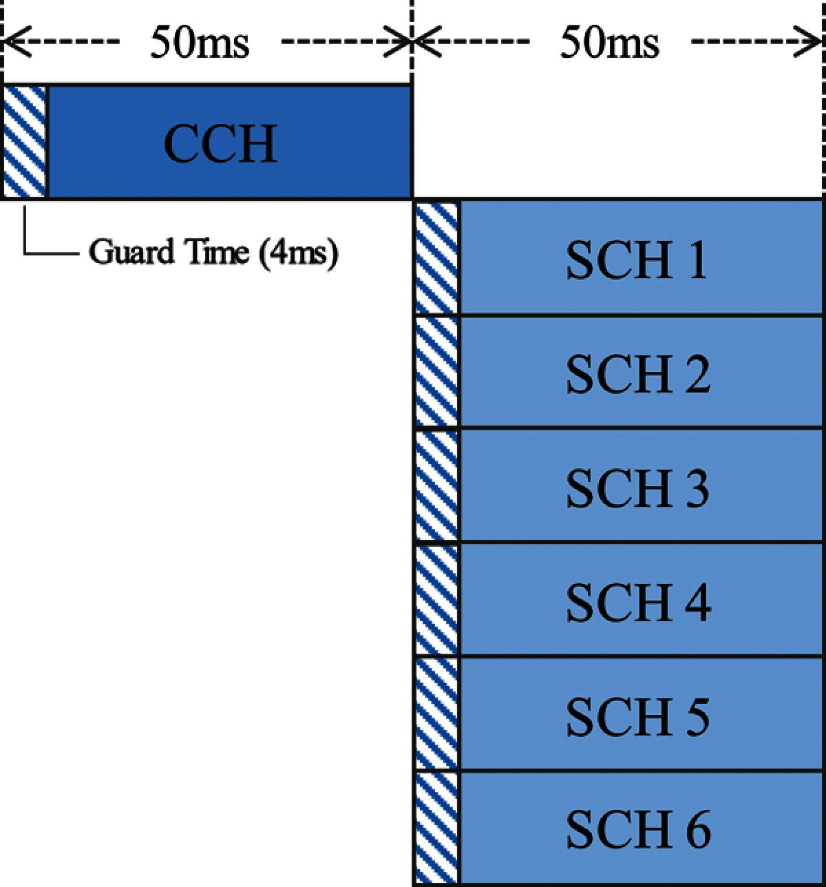
Figure 2: Period structure of DSRC channel
The techniques for dynamically adjusting the CCH and SCH interval [7,8] calculate each channel's utilization. The interval of those channels is adjusted such that the more utilized channel has longer interval; SCH interval is extended on low utilization of CCH. This method also increases channel utilization by allocating the bandwidth of underutilized channels. However, it is difficult to synchronize the periods of all vehicles because of their high mobility and changing network topology. If the period of the channel changes dynamically, the message arrival time varies, which makes it difficult to ensure that the safety messages arrive within the required time. Using two CCHs and five SCHs instead of one CCH and six SCHs [9] increased the number of CCH channels to improve the stability of safety message-delivery. However, it is difficult to conclude that the overall performance increased, because the number of SCH channels was reduced by one, which decreased the rate of non-safety messages.
IEEE 802.11p, defined as the standard MAC protocol, is based on CSMA/CA. It avoids contentions by checking whether a channel is idle before accessing the channel [11]. However, if multiple nodes access the channel at the same time, the signals overlap, and no packets are delivered. As the number of nodes increases, the number of packet collisions grows exponentially, so the channel access delay cannot be guaranteed [12–15]. Accordingly, the TDMA MAC protocol, which avoids contentions by allocating timeslots, is utilized efficiently in VANET. The main consideration of TDMA in VANET is assigning a timeslot to each vehicle. According to the protocol, the system is divided into a distributed structure and a centralized structure. In the distributed structure [16,17], each vehicle directly selects an empty timeslot to occupy and informs the surrounding vehicles that the timeslot is in use. There is no need for a manager node, so there is no point of failure that can be caused by a manager node. However, a contention collision is possible when multiple vehicles attempt to reserve the same slot simultaneously. An encounter collision can occur when vehicles using the same slot run into each other.
However, the centralized structure avoids contention collisions [18–21] because the central node also allocates an empty slot to each vehicle. In the centralized structure of TDMA, the central node must allocate timeslots efficiently and equitably to each vehicle. In VANET, an RSU with abundant hardware resources or a header of the cluster can act as a central node. An RSU is a hardware installation that supports the ITS by providing communications and computing resources for its assigned section of the road. However, there are some drawbacks to using an RSU as a central node. Timeslots need to be allocated very frequently because the vehicles move and the RSU does not. Clustering can be used in a centralized structure to prevent packet collisions and to use bandwidth efficiently. A cluster has at least one cluster header, which manages the cluster and cluster members, and increases management efficiency if it manages the timeslots. Contention collisions in a centralized structure can be resolved because the cluster header allocates timeslots. However, the possibility of encounter collisions remains. A study in [22] investigated the problem by identifying in advance which vehicles with the same timeslot would collide. This technique had all vehicles broadcast the timeslot they were using to two-hop. Based on this information, the middle vehicle forecasted whether timeslots would overlap then took measures to prevent the collision. However, bandwidth wasting remained because timeslot information had to be continuously broadcast to two-hop.
One important factor to consider in the vehicular network is the direction that a vehicle is moving. If the direction of the traffic is not considered, the mobility of a vehicle may not be reflected realistically in the simulation. However, allocating different sets of timeslots for vehicles moving in opposite directions [23] prevented packet collisions involving those vehicles. The method [24] that improved the road directionality in this study considered that saturation of the road might depend on the direction of traffic. The number of timeslots for each road direction is not allocated equally but according to the road's saturation status, resulting in an efficient response to road saturation.
Studies have improved the TDMA MAC protocol, clustering, and multichannel utilization to reduce the instability and packet collision rate of wireless vehicle communication, compared to the 802.11p scheme. However, safety requires that vehicular communication consider packet delivery and road characteristics. Although studies have been done to reduce the collision rate of packets using TDMA and clustering [16–21], the studies could not maximize the use of bandwidth because of inefficient DSRC multichannel usage and not considering the bidirectionality of the road traffic.
In addition, existing studies have focused only on improving the performance of vehicular wireless communication rather than supporting safety applications. However, traffic safety applications such as autonomous driving or platooning have exceedingly high computational complexity. Therefore, RSU, which has higher computing power than a vehicle, can be efficiently utilized as a node that performs calculations for traffic safety applications.
In the case of the frequency division multiple access (FDMA) method for VANET, the frequency is divided into several parts so that multiple vehicles can communicate within one bandwidth at the same time. However, interference may occur in communication due to the decreased frequency, and since the vehicle occupies one frequency continuously, there can exist a range of bandwidths being unnecessarily occupied. In code division multiple access (CDMA), signals are encrypted and decoded through a pseudo-noise (PN) code, allowing multiple nodes to communicate simultaneously within the same bandwidth. Since multiple vehicles can communicate simultaneously while fully using the bandwidth, bandwidth efficiency and security can be enhanced through code encryption and decryption. The main issue of CDMA in VANET is allocating the PN code to different vehicles. For a large number of vehicles, a unique PN code must be assigned to each vehicle. In this case, the length of the code becomes too long for VANET applications to accommodate it. One solution is to allocate PN codes dynamically, but this increases overhead due to the high complexity.
Moreover, CDMA is not suitable when many vehicles must be accommodated because the performance decreases when the number of vehicles increases. The space division multiple access (SDMA) method divides roads into equal segments and allocates a different channel to each. However, the vehicles’ high mobility causes the channel to be switched continuously, leading to a much higher overhead.
3 Vehicular Safety Supporting System (V3S)
The vehicular safety supporting system (V3S) provides a V2X communication environment that can reliably transmit and receive BSM every 100 ms, even when the number of vehicles increases. The proposed system solves such problems as broadcast storms, hidden nodes, and packet collisions. It also solves the low-bandwidth problem of DSRC through a clustering-based TDMA MAC protocol and a DSRC channel control scheme. In this section, we introduce the cluster structure, channels, and configuration modules of V3S.
The proposed V3S is designed to increase bandwidth efficiency by collecting BSMs from vehicles through clustering to reduce the number of packets and the packet collision rate.
The physical components of the V3S are the vehicles consisting of the cluster and the RSU. The logical components of the system include non-members not joined to the cluster, cluster members joined to the cluster, the main cluster header that manages the cluster, and the subcluster headers that replace the main cluster when a problem occurs. Fig. 3 shows that all vehicles change their states through the clustering process.
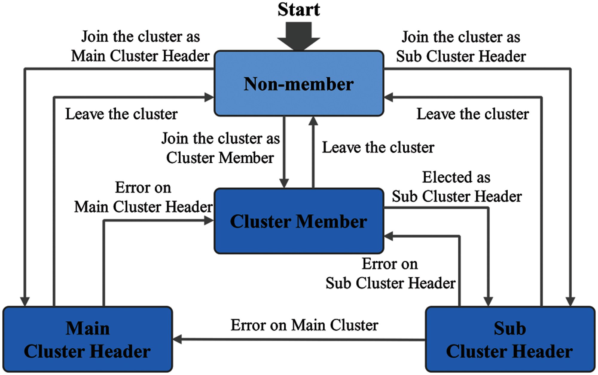
Figure 3: Role transition diagram of vehicle through clustering process
Non-members announce themselves by broadcasting BSMs every 100 ms, which is the minimum time for message transmission to ensure the cluster configuration's safety. If three or more non-member vehicles are nearby (the basis for cluster creation), a new cluster is formed.
The cluster member receives its own number and the length of its timeslot from the cluster header and broadcasts a BSM in the timeslot. The message will be used later to support safe platooning.
In V3S clusters, there is one main cluster header and two subcluster headers. The main cluster header informs the cluster members of the CCH and SCH period order with the SCH channel number and allocates a timeslot. The subcluster header takes over the role of the main cluster when the main cluster header fails.
The main cluster header collects BSMs sent by cluster members and delivers them to the RSU. Because BSMs are crucial to safety applications, the aggregated messages should be checked for errors. The main cluster header and subcluster headers collect BSMs sent by the cluster members and exchange their value hashed with the MD5 algorithm to see whether there is an error. If there is no error, the main cluster header transmits the aggregated messages to the RSU. However, if there is an error, the failed cluster header is changed to a cluster member, and a new cluster header is selected from among the subcluster headers. Three cluster headers are used to reach consensus for error detection. The efficiency is best for the number of nodes used for consensus when there are three units [25].
When vehicles form a cluster, the RSU serves as the manager that informs the cluster of available channels by reporting the period order of the SCH and CCH channels and exchanging information with neighboring RSUs. In addition, as shown in Fig. 4, the RSU collects all the information of the BSM from the area in charge, providing support for further safety applications.
In this paper, we solve the encounter collision problem of the centralized structure in two ways. First, the channel structure of the proposed system is designed to prevent nodes from using the same SCH channel by maintaining the cluster range at 200 m. Since the maximum transmission range of DSRC is 1 km, clusters using the same channel must be at least 1 km apart. Therefore, in Fig. 5, because there are five clusters with channels assigned sequentially between SCH1s, clusters using the same channel cannot exist in the same DSRC range. However, because road traffic is bidirectional, there arises a problem with the same cluster channel as the cluster on the opposite side of the lane.
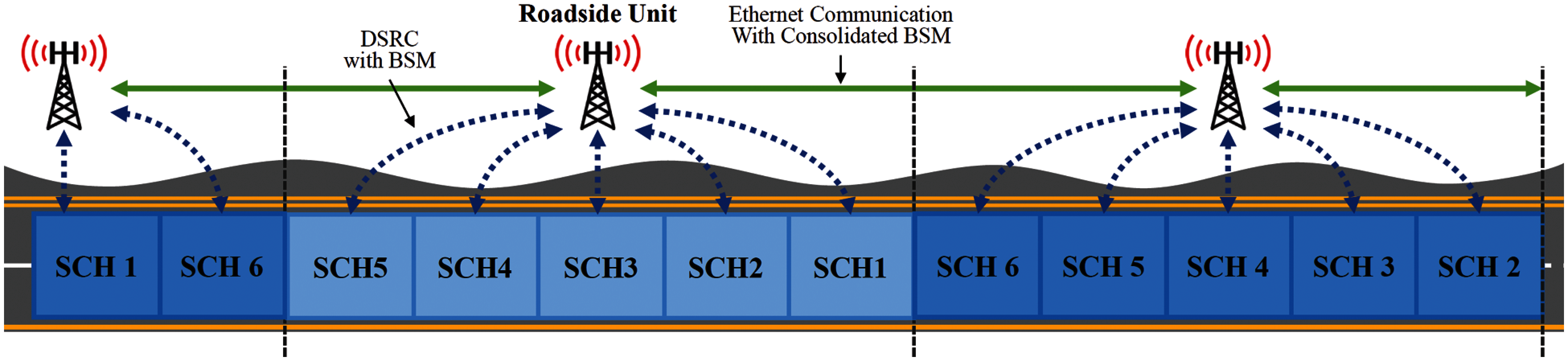
Figure 4: Data transmission and reception between RSUs
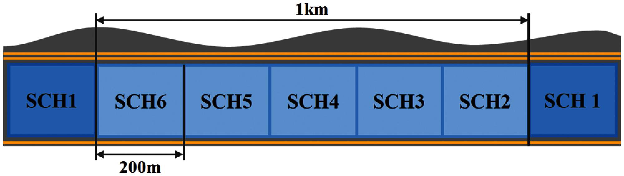
Figure 5: Range configuration in V3S
Second, the V3S channel structure provides the DSRC channel period according to the traffic direction, as shown in Fig. 6. The direction is assumed to be obtained by the BSM. If DSRC is used in the CCH-SCH order in one direction, the opposite lane uses the DSRC in the SCH-CCH order. This makes vehicles in each lane use opposite channels at the same time. Therefore, the problem of overlapping channels in opposite directions does not occur, effectively solving the problem of encounter collisions.
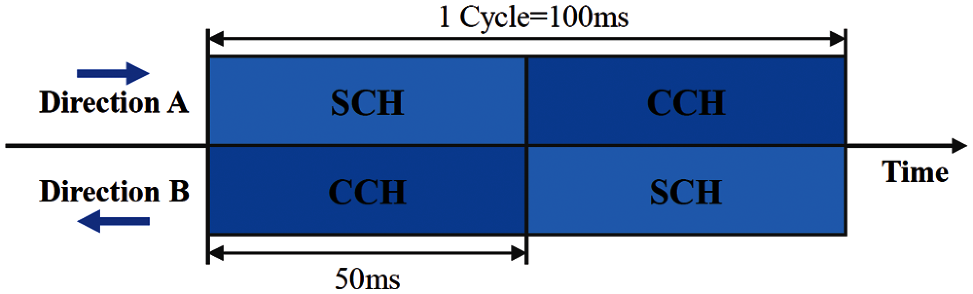
Figure 6: Channel structure according to the direction of road traffic in V3S
An SCH of the V3S is used for intra-cluster communication. In addition, it uses the TDMA scheme to solve packet collisions and network performance degradation caused by increased contention for DSRC communication due to an increase in the number of cluster members. To support the TDMA scheme in the V3S, the cluster header allocates timeslots to cluster members. The cluster member broadcasts the BSM during the assigned timeslot period. The CCH of the V3S operates by the CSMA/CA method, which enables autonomous DSRC communication link contention. It is used for communication outside the cluster where there is relatively little communication between nodes, such as communication between cluster headers, non-members, and RSUs.
Fig. 7 shows the overall structure of the proposed system V3S. The system is divided into vehicle modules and RSU modules. The vehicle module consists of a BSM broadcaster to transmit BSMs to all vehicles, a cluster creation manager to form a cluster of non-member vehicles, a cluster join manager, a BSM manager, a timeslot manager, and a cluster range manager for the cluster header. The RSU module consists of an RSU broadcaster, a BSM receiver, and a channel manager for the RSU to manage vehicles and clusters.
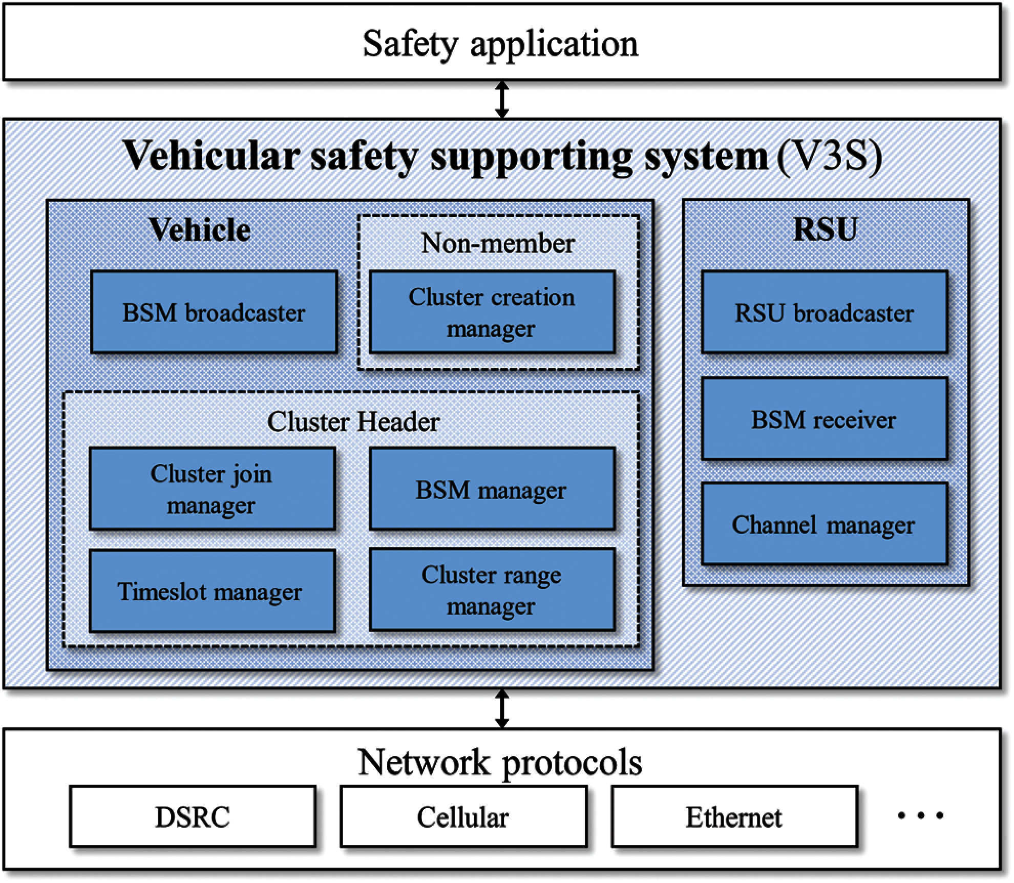
Figure 7: Module components of V3S
The BSM broadcaster makes all vehicles broadcast their BSM for road safety. A non-member vehicle does not have an assigned SCH channel because it is not joined to the cluster, so a BSM is transmitted during the CCH period. In contrast, SCH channel timeslots are allocated to the cluster members by the cluster header, so a BSM is transmitted to the SCH channel period's timeslots.
The cluster creation manager is a process in which non-member vehicles are not joined to the cluster form. If there is no cluster around the vehicle within 200 m when entering the road, the non-member vehicle forms a new cluster. The condition for creating a new cluster is for there to be at least three non-member vehicles within 200 m. When the condition is satisfied through the BSM sent by non-member vehicles, three or more non-member vehicles elect a cluster header to form a cluster. The cluster header is selected by the absolute value of the difference in speed, the received signal strength indication (RSSI) value, and the delay time needed for the BSM to reach itself from other non-member vehicles through the received BSM. The delay in receiving a BSM is calculated as the difference between the BSM's timestamp and the current timestamp. The RSSI value uses the timestamp of the BSM. The speed difference from the vehicle is obtained with the absolute value of the difference between the speed value contained in the BSM and the speed of the vehicle currently being calculated.
Since the three elements have different values, the cluster header suitability is measured through normalization. The variables used in the equation for selecting the cluster header are defined in Tab. 1.
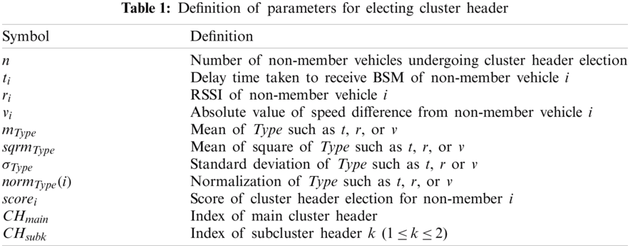
Non-member vehicles undergoing cluster header election receive
The normalized value for each variable is calculated using the results of Eqs. (1)–(3). Normalization for each variable
After the normalized value is obtained, the score
After calculating the BSM message scores from all non-member vehicles participating in the cluster header election, each vehicle broadcasts the other's calculation result. Non-member vehicles that have received all result messages can check their score results against those transmitted by other vehicles. (Each non-member vehicle compares the scores of n vehicles, including itself). The vehicle with the highest score is selected as the main cluster header and the two vehicles with the second and third highest values become the subcluster headers. Eq. (6) determines the main cluster header and two subcluster headers.
The cluster join manager is a module that joins non-members to a cluster. The condition for joining a cluster is that the available timeslot must remain in the SCH channel of the cluster and that the non-member joining must be within 200 m of the cluster. The cluster header joins non-members that satisfy both conditions to the cluster. The cluster header informs the newly joined non-member through the CCH channel of the SCH channel number of the cluster, the CCH/SCH channel cycle order according to the direction of traffic, and the vehicle's timeslot number. Timeslot numbers are assigned sequentially from the lowest unused number. If a cluster member leaves the cluster, the number becomes an unused number.
The BSM manager aggregates the BSMs sent by cluster members into one message and transmits it to the RSU. The aggregation removes the multiple packet headers, packet collisions, and backoff times that exist in a separate transmission. Since the BSMs are the most critical information for operating safety applications, the reliability of messages must be guaranteed. Therefore, before the aggregated BSM is delivered to the RSU, the main cluster header and the subcluster headers check for errors through a consensus process.
For error detection, the main cluster header and the two subcluster headers exchange the 16-byte result from the MD5 hashing algorithm that has taken the aggregated BSM as a parameter in the consensus timeslot shown in Fig. 8. If the hash values all match, the main cluster header determines that there is no abnormality in the aggregated message and transmits it to the RSU. If only the hash value of the main cluster header is different, it is determined that there is a problem with the main cluster header, and the first subcluster header sends the aggregated message to the RSU instead. The first subcluster header is then changed to the main cluster, and a new subcluster header is elected. If the hash value of one subcluster header is different, the main cluster header sends an aggregated message to the RSU, and a new subcluster header is elected and replaces the subcluster header with the error. When all cluster headers have different hash values, two new subcluster headers are elected after the main cluster header transmits an aggregated message. In the election of a new subcluster header, the main cluster header is selected in the same manner as was the cluster header by the cluster creation manager.

Figure 8: Structure of SCH Channel
The timeslot manager manages timeslots when the period is the cluster maintenance interval shown in Fig. 8. The most important factors in the management of timeslots are the size and the number of the timeslots. The size of the timeslot is the time it takes to send one BSM in the current DSRC bandwidth
The number of SCH timeslots also indicates the maximum number of cluster members that a cluster can have. If the guard time, the cluster maintenance time, and the consensus time are
That is, the value obtained by dividing the remaining available time excluding the guard time needed to prevent interference from the channel-switching time, the cluster maintenance time, and the consensus time from the 50 ms of the SCH by
In the V3S, the length of a single cluster is 200 m, and up to 100 vehicles, each 2 m long, can be in one lane. As shown in Fig. 10, the V3S uses two bytes for the Total Number of Timeslot value, which allows the system to allocate 65,536 timeslots supporting 655 lanes. Since
The cluster range manager maintains the cluster range of the cluster header at 200 m. As shown in Fig. 9, the range of the cluster is set to 200 m starting from the end of the preceding cluster, and if there is no preceding cluster, it is set to 200 m based on the first vehicle within the cluster. Thus, the entire range of the cluster moves together with the vehicle, thereby continuously maintaining the cluster range. As a result, the hidden node problem can be solved because interference between SCH channels does not occur, preventing packet collisions. If a cluster header gets out of its cluster range and gets into the next cluster range, it is demoted to a non-member. This is possible because the RSU collects BSMs, and the channel manager allocates SCH channels to clusters.
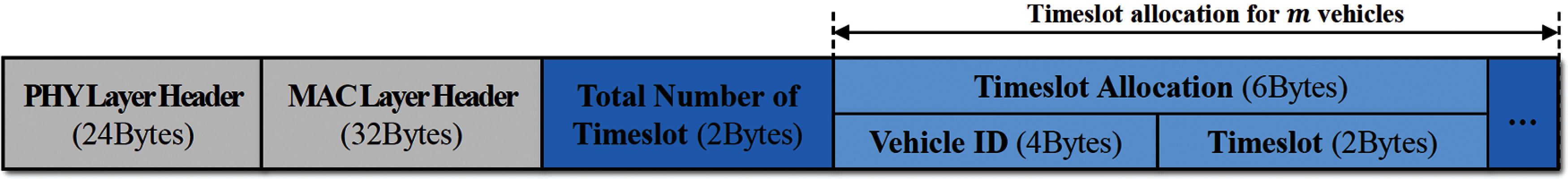
Figure 9: Packet structure for managing cluster of cluster maintenance interval
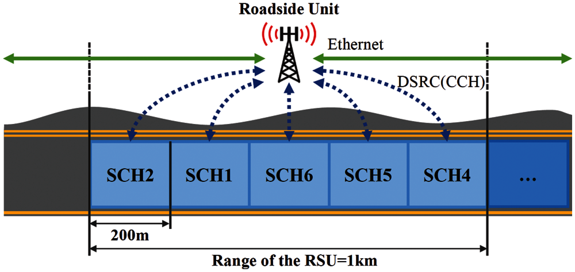
Figure 10: Maintenance of cluster range
The RSU broadcaster allows the RSU to broadcast its information to nearby vehicles, which check the information about the RSU in the vicinity and the area covered by the RSU.
The RSU receiver receives the aggregated BSM sent by the RSU and disseminates it to RSUs on both sides. The RSU receives the aggregated BSM from the neighboring RSU and allows it to be used in SCH channel number assignment through the channel manager or used for safety applications.
The channel manager manages the CCH/SCH cycle according to the SCH channel number of the clusters and the vehicle traffic direction; then, it checks whether the SCH channel is correctly maintained for every period. Fig. 11 shows an RSU allocating SCH numbers. The SCH number is unique for each cluster and must be sequentially allocated to prevent channel overlapping while communicating effectively. When a new cluster is formed, the RSU uses the RSU receiver to identify information on the SCH channel used by neighboring RSU clusters and allocates the SCH channel number. If a new cluster is created without other clusters within 1 km of the front, SCH channel 1 is allocated because the same SCH channel number does not cause encounter collisions due to overlapping. However, if other clusters exist within 1 km, the clusters allocated with the same SCH channel number will overlap. The channel manager then solves the encounter collision problem by changing the SCH channel of the cluster group at the rear.

Figure 11: Disseminating aggregated BSM of RSU and allocating SCH numbers
The V3S must reliably send a BSM every 100 ms to support safety applications, even when the number of vehicles increases. This section analyzes the extent to which the V3S can support vehicles according to the DSRC bandwidth. The most important factor of vehicle capacity in the V3S is the number of vehicles that can join a cluster. Therefore, it is necessary to calculate the maximum vehicle capacity of the cluster.
Assuming that
If l is the size of a BSM, m is the maximum number of vehicles that the cluster can support, the total number of timeslots is two bytes, and the size of data required to change the timeslot number for all m vehicles is
Since CCH and SCH are switched alternately, the SCH interval in Eq. (10) must be less than 50 ms. Through Eq. (10), the maximum number of vehicles in the cluster can be calculated using the AIFS, the packet header's size, and the DSRC network bandwidth. Fig. 12 shows the number of vehicles in the cluster according to DSRC bandwidth. The AIFS is set to 58 us, as used in in-vehicle communication [26], the header to 56 bytes as the sum of the length of MAC layer and physical layer header length [27], and the BSM payload for the basic configuration of 39 bytes [2].
In Fig. 12, even if the DSRC minimum bandwidth is 3 Mbps for one-way traffic, up to 140 vehicles can be joined in one cluster. If the maximum bandwidth is 27 Mbps, more than 500 vehicles can be joined. In the extreme case that the vehicle length is two meters and there is no space between the vehicles, 500 of them can be accommodated on a five-lane road. In allocating different timeslots according to the direction of the road traffic on a two-way road [23], the number of available channels is reduced by half because the DSRC communication channels are allocated without overlapping for both directions of the road. Therefore, only a small number of vehicles can be supported. However, communication in the V3S is switched between the SCH and the CCH according to the direction of traffic. For this reason, the number of vehicles that can be supported in a cluster in the V3S is the same as in the one-way case, making it possible for more vehicles to be reliably supported than with other studies.
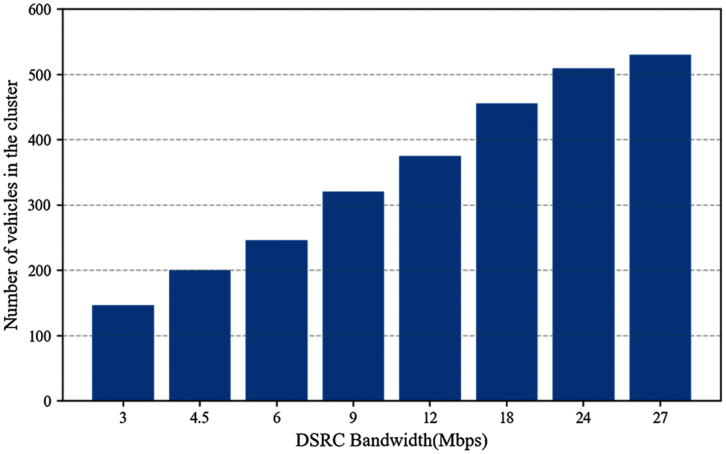
Figure 12: Number of vehicles in the cluster according to DSRC (BSM Payload = 39 Bytes)
Fig. 13 is the result of calculating the maximum number of vehicles in the cluster according to the bandwidth when the BSM payload is doubled. The result shows that the number of vehicles in the cluster decreased by 21.92% on average from that of the default 39 bytes. A header is present in every packet, and the bandwidth is occupied by messages other than AIFS and BSM.
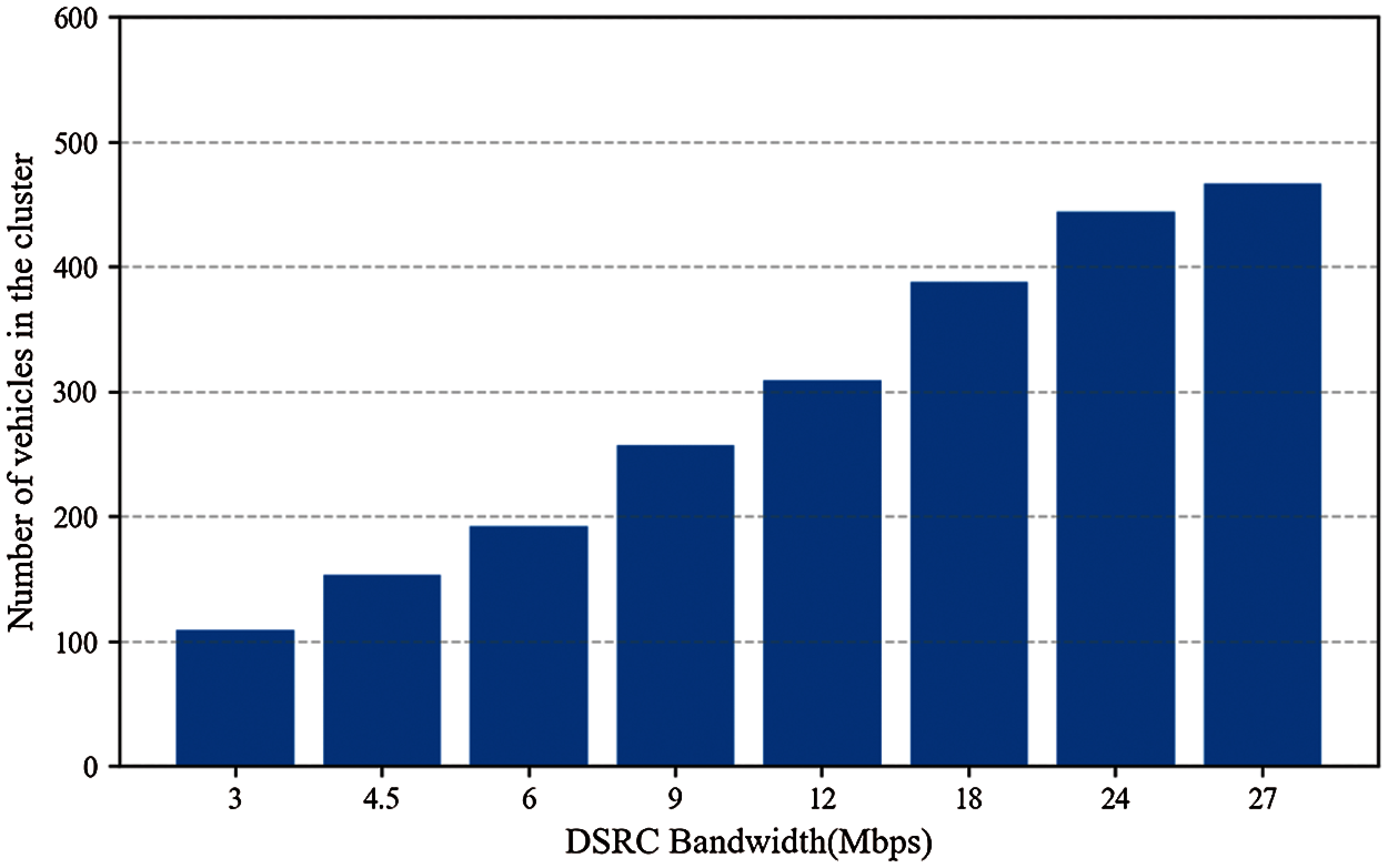
Figure 13: Number of vehicles in the cluster according to DSRC (BSM Payload = 78 Bytes)
To test the performance of the V3S, vehicles communicating on a virtual road were simulated using the vehicle-in-network simulation (Veins) framework [28]. The Veins framework is used to simulate vehicle networks in network environments of road traffic. It is based on the simulation of urban mobility (SUMO) [29], a road traffic simulator, and OMNet++ [30], an event-based network simulator. For communication on the V2X, the protocol specified in the 802.11p standard was used. The existing works in the literature do not open the implementation details. Instead, we compared 802.11p which is implemented in the Veins framework as a baseline for the comparison.
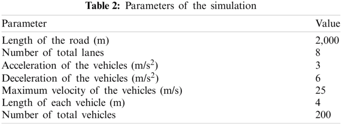
A highway environment was simulated with virtual RSUs located at 1 km intervals along the highway and set to communicate with other RSUs by a wired Ethernet network. The highway is a two-way, straight eight-lane road, with four lanes in each direction. The proposed V3S was compared with the current 802.11p method by measuring the packet error rates for each bandwidth of DSRC through simulation. The simulation scenario started when two vehicles heading in opposite directions enter the road. It ended when one cluster passed the other. Both vehicles entered arbitrary lanes. The simulation parameters are shown in Tab. 2.
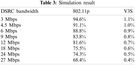
The simulation results are shown in Fig. 14 and Tab. 3. Both 802.11p and the V3S showed a decrease in the packet error rate with increased bandwidth. For the 802.11p, the average packet error rate according to the bandwidth of DSRC was about 82%; however, in the V3S, it was less than 1%. Because there were 200 vehicles on the road, the 802.11p had an extremely high packet error rate, so normal BSM transmission was not possible. In contrast, V3S shows a low packet error rate of about 1% even with a low 3 Mbps bandwidth, and it transmits packets more reliably than the 802.11p. In conclusion, the 802.11p cannot provide normal, reliable packet delivery, which becomes nearly impossible at low bandwidths. In contrast, the V3S transmits packets reliably, even at low bandwidths. The low packet error rate contributes to the overall network throughput and delay, since the lower error rate requires reduced retransmission of packets.
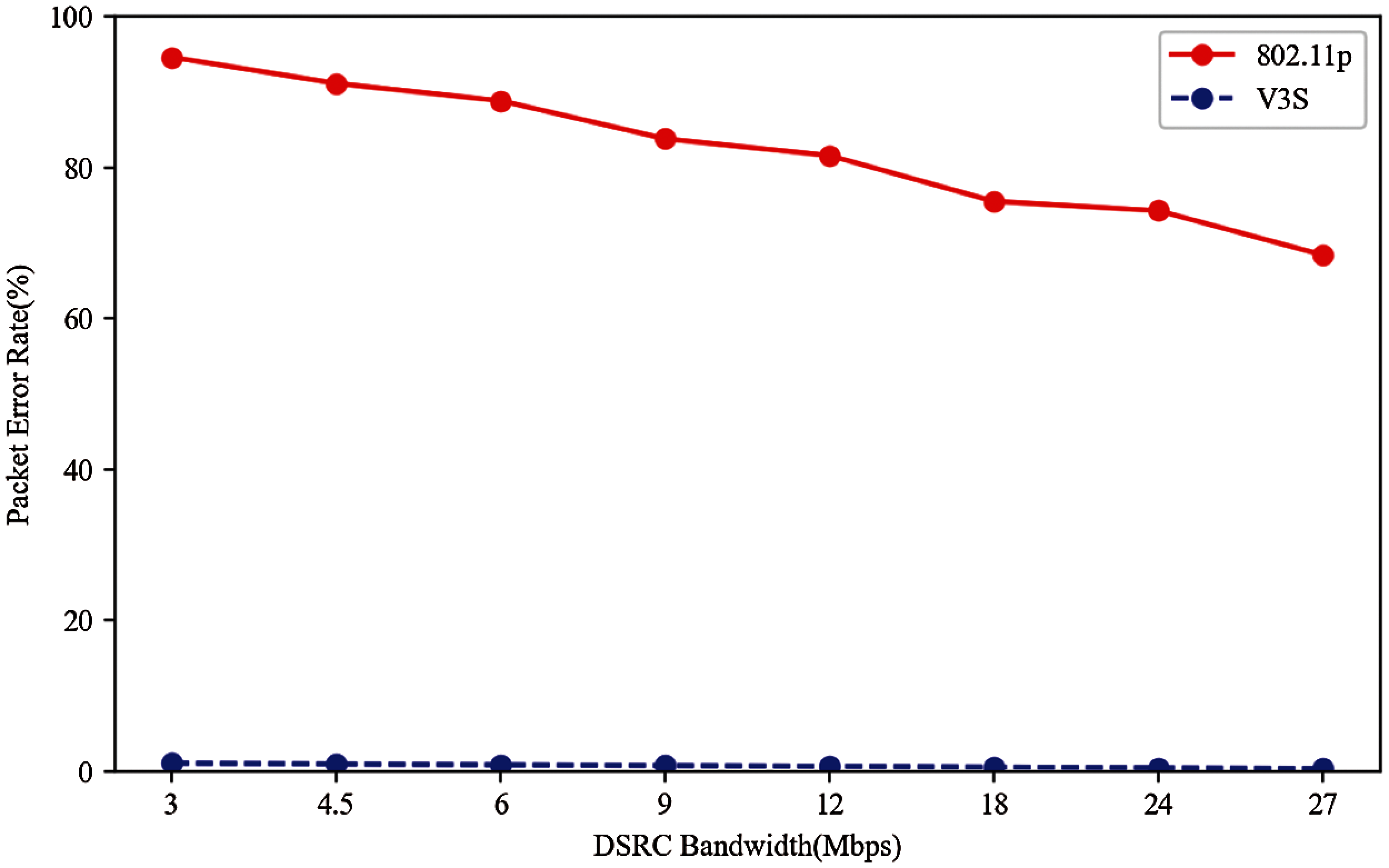
Figure 14: Packet error rate according to the bandwidth of DSRC
The V3S was proposed to overcome the high mobility of vehicles, the instability, and the low bandwidth of the vehicular wireless communication environment. The system supports safety applications and provides a communication environment where all vehicles can transmit their BSMs reliably every 100 ms. The V3S efficiently manages bandwidth through clustering and lowers the wireless packet collision rate by broadcasting packets in predetermined timeslots using the TDMA MAC protocol. Vehicles and RSUs can transmit more data without increasing the transmission delay. As a result of the simulation, the 802.11p had an average packet error rate according to the bandwidth of each DSRC of 82%. In contrast, the V3S showed a packet error rate of less than 1%, demonstrating a stable transmission rate.
This study considered BSM transmission and reception for safety applications over the entire network bandwidth. However, executing the safety application correctly required the computation delay of the application to be considered for transmission and reception of the BSMs to be stable. Therefore, it is necessary to study a distributed computing technique that considers the communication environment between vehicles to improve the execution of real-time safety applications. In addition, when the DSRC bandwidth was changed in the current study, the information about changed time slots was transmitted for all cluster members. Therefore, it is also necessary to study a method for efficient network usage that involves transmitting information only to vehicles whose timeslot has been changed.
Funding Statement: This work was supported in part by the Chung-Ang University Research Grants in 2019, and in part by R&D Program for Forest Science Technology (Project No. “2021338C10-2123-CD02) provided by Korea Forest Service (Korea Forestry Promotion Institute).
Conflicts of Interest: The authors declare that they have no conflicts of interest to report regarding the present study.
 | This work is licensed under a Creative Commons Attribution 4.0 International License, which permits unrestricted use, distribution, and reproduction in any medium, provided the original work is properly cited. |