DOI:10.32604/cmc.2022.021644
| Computers, Materials & Continua DOI:10.32604/cmc.2022.021644 | |
| Article |
Ultra-wideband Frequency Selective Surface for Communication Applications
1Department of Electrical and Computer Engineering, COMSATS University Islamabad, Islamabad, 45550, Pakistan
2Department of Electrical and Computer Engineering, King Abdulaziz University, Jeddah, Kingdom of Saudi Arabia
3School of Electronics and Computer Science, University of Southampton, Southampton, SO17 1BJ, UK
4School of Engineering, Faculty of Science and Engineering, Macquarie University, Sydney, NSW, 2109, Australia
5BENELEC, Botany, Sydney, NSW, 2019, Australia
*Corresponding Author: Muhammad Fasih Uddin Butt. Email: fasih@comsats.edu.pk
Received: 08 July 2021; Accepted: 09 August 2021
Abstract: A low-profile ultra-wideband (UWB) band-stop frequency selective surface (FSS) is designed for S-, C-, X- and Ku-bands communication applications. The FSS is constructed by using square and circular loop elements printed on the top and bottom sides of the RO3210 substrate. The FSS has been designed to reduce the electromagnetic interference (EMI) as well as to mitigate the harmful effects of electromagnetic radiation on the human body caused by different radio devices. The dimension and size of the UWB FSS have been reduced to 0.12 λ × 0.12 λ and 90%, respectively, as compared to the reported literature. The other advantages of the proposed FSS are that it is low profile, it has a simplified geometry and it ensures better angular and polarization stability of up to 85°. The –10 and –20 dB bandwidths of the proposed FSS are 146% (2.0–13.0 GHz) and 80% (4.87–11.42 GHz), respectively. Theoretical results have been obtained using ANSYS HFSS and verified through measured results.
Keywords: Electromagnetic radiation; fractional bandwidth; polarization; transverse electric; transverse magnetic
The study on electromagnetic radiation has received significant attention due to its harmful effects on the performance of radio equipment as well as on the human body [1]. Proliferation in wireless technology has increased electromagnetic radiations caused by different radio devices and transceivers operating on different frequency bands. The electromagnetic interference (EMI) produced by different transmitters has become a significant challenge for the researchers. EMI degrades the performance and operations of wireless and mobile networks. This degradation in wireless systems happens due to electromagnetic induction or electrostatic coupling [2]. Human health has also been affected due to electromagnetic radiations with the proliferation in mobile and wireless technology [3]. Both artificial and natural sources initiate EMI. For example, mobile and satellite networks, ignition systems, lightening and aircrafts etc. produce variable currents and voltages which degrades the performance of a wireless network. Many solutions have been proposed by different researchers to mitigate the harmful effects of EMI. Researchers have recommended different techniques of electromagnetic shielding for wireless systems operating on very low frequencies [4]. They proposed electromagnetic bandgap structures [5,6], thin metal films [7], metamaterials [8,9] and frequency selective surfaces (FSSs) [10] to resolve the malfunctioning of radio devices due to electromagnetic radiations. However, FSSs have various advantages over these techniques to address the EMI. The periodic structures of FSS are of low cost, lightweight, low profile and easy to design. FSS can be designed to act as a spatial filter, reflectors, polarizer, and absorber to enhance the performance of various telecommunication systems. It can be incorporated into a system to act as a band-stop filter for effective isolation from unwanted signals. The researchers have used different numerical techniques like finite element method (FEM), method of moments (MOM), equivalent circuit model (ECM) and spectral element methods (SEM) to analyze the behavior of electromagnetic (EM) waves through FSSs [11]. FEM has comparable precision to SEM as both have similar number of interpolant points [12]. SEM technique has been shown to achieve high accuracy for a variety of applications [13–18]. In [4], GSM 1800 band has been shielded with 1.3 GHz rejection bandwidth (BW) having signal attenuation of –20 dB. In [5], the authors have designed a FSS for Ku band on a flat glass by using cross-slot elements for EMI shielding having 0.7 GHz BW with –10 dB signal attenuation. In [19], a polarization independent FSS is presented for UWB applications having fractional bandwidth (FBW) of 86.9%. The FSS operates for 0° and 30° angle of incidence having BW of 8 GHz with –10 dB attenuation. In [20], the authors have used cross dipole and circular loop elements to design wideband FSS to achieve shielding effectiveness (SE) for X- and Ka- bands. The angular stability was ensured for 0° and 45° incidence having 7.5 GHz bandwidth with –10 dB attenuation. A dual layer FSS of 8 GHz bandwidth was presented in [21]. FBW of 114% was achieved for only normal incidence. In [22] and [23] authors have presented a band-stop FSS with FBW of 48% for X- band applications. They investigated angular and polarization stability for normal and oblique angles of incidence. A wideband band-stop FSS of 8 GHz bandwidth with –10 dB attenuation was investigated in [24] for normal angle of incidence. FBW of the proposed FSS was achieved 89%. A single layer tri-band FSS for shielding applications was investigated in [25]. The angular stability was ensured for both TE and TM excitations for up to 50° incidence. The proposed FSS was designed to operate for WiMAX, WLAN and X-band shielding applications. Authors have discussed the advantages of convoluted FSS over the conventional loop elements in [26]. Angular as well as polarization stability of up to 50° angle of incidence with 120% FBW was ensured at –10 dB attenuation. In [27] and [28], the impact of low and high permittivity values is investigated, respectively. The band-stop FSS of 2.41 GHz, and 1.50 GHz were designed for EMI reduction applications. In [4–10] and [19–30], researchers have proposed unique designs to mitigate the effects of EMI and to improve isolation in UWB and 5G applications [31–33]. However, some important parameters of FSSs such as thickness, bandwidth, fractional bandwidth, periodicity, signal attenuation, angular stability for horizontal and vertical polarizations schemes need to be further investigated to enhance the performance of the FSS for EMI reduction applications. This paper presents a low profile, compact and lightweight dual-layer UWB FSS for S-, C-, X- and Ku- bands applications. Based on the following novel characteristics, the proposed FSS is appropriate to enhance the performance of different radio equipment by reducing EMI:
• Bandwidth of the proposed FSS is of 11 and 6.55 GHz with an attenuation of –10 and –20 dB ranging from 2–13 GHz and 4.87–11.42 GHz, respectively.
• FBW of the proposed FSS at –10 and –20 dB levels are 146% and 80%, respectively.
• Angular and polarization stability of UWB FSS is achieved of up to 85° incidence as the gap between the two adjacent elements has been reduced to λ/8 at center frequency.
• To make it low-profile and lightweight, dimension and size of the FSS has been reduced to 0.12 λ and 94% at the center frequency, respectively.
• The thickness of the FSS has been reduced to λ/31 as compared to the thickness of multi-layer FSS which is λ/4, proposed in [21].
Figs. 1a–1c show the 3D view, dimensions, and layout of the unit cell of UWB FSS. The length (L) and width (W) of the unit cell is 4.98 mm along x- and y-axis. The dielectric permittivity (ε) of the substrate is 10, whereas loss tangent is 0.003. For theoretical analysis, square and circular elements are modeled as a perfect conductor. The thickness of each element is 0.035 mm. The length (L) and the outer radius (R) of square-loop and circular-loop FSS are calculated using the below equations.
In the above equations, the speed of light is represented by c, the dielectric permittivity by ε, operating frequency by
where d, λ and D are representing the far-field distance between the Tx and Rx antennas, the wavelength, and the maximum dimension of horn antennas, respectively. The simulation and measured transmission coefficients of UWB FSS are presented in Figs. 5a and 5b. Tab. 1 summarizes –10 dB BW of the proposed FSS for fl and fh resonance frequencies for transmission coefficients for both 0° and 85° angles of incidence. It is quite clear that there is a great similarity in theoretical and experimental results as shown in Figs. 5a and 5b. Fig. 6 shows the physics of UWB FSS when a unit cell is excited by a plane wave at 7.5 GHz. Higher current density can be observed on the surface of MSLFSS and circular-loop element along z+-axis at 7.5 GHz. This phenomenon is also demonstrating the reflection or band-stop characteristics of the UWB FSS.
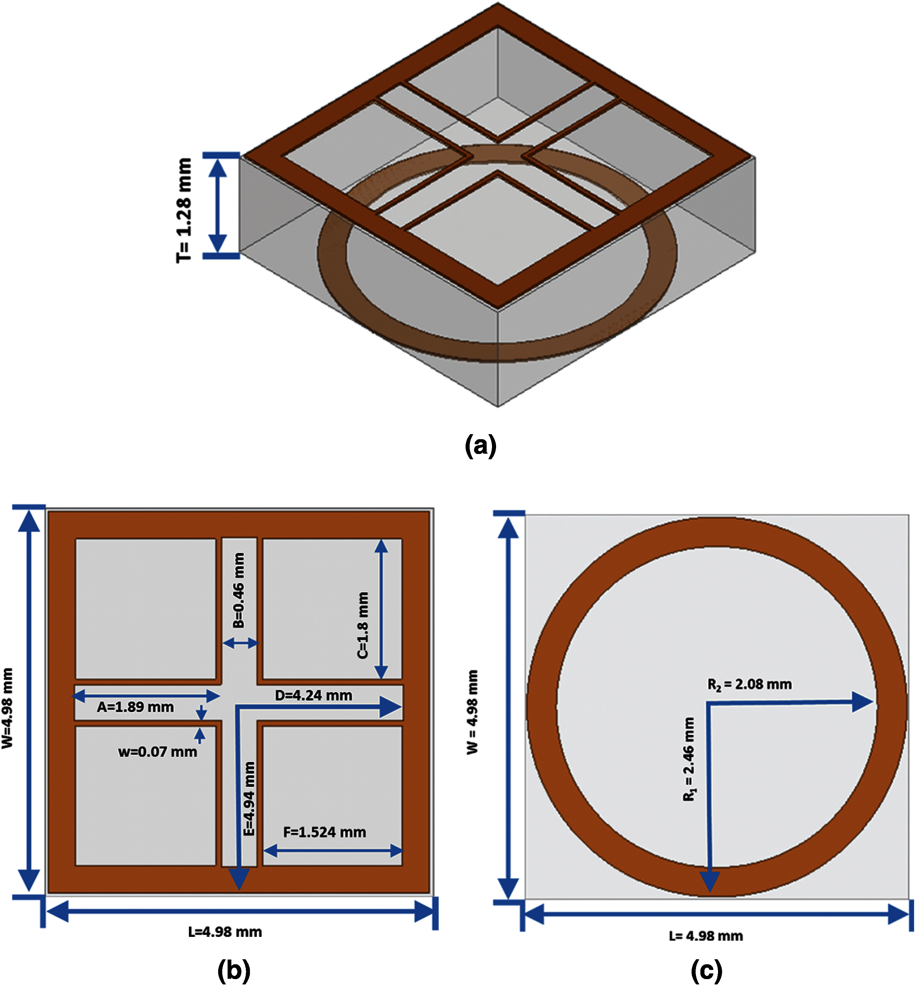
Figure 1: Geometry of dual layer UWB FSS, (a) 3D-view of UWB FSS unit cell, (b) upper view of square loop element, (c) bottom view of circular loop element
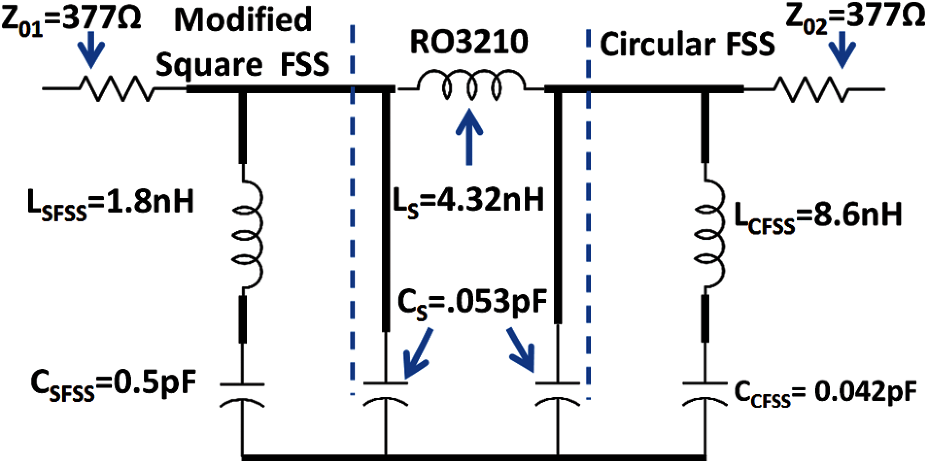
Figure 2: Equivalent circuit model (ECM) of the proposed UWB FSS
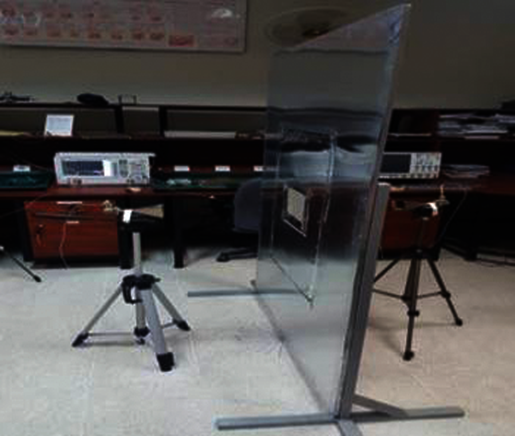
Figure 3: Experimental setup to measure the transmission response of the proposed FSS
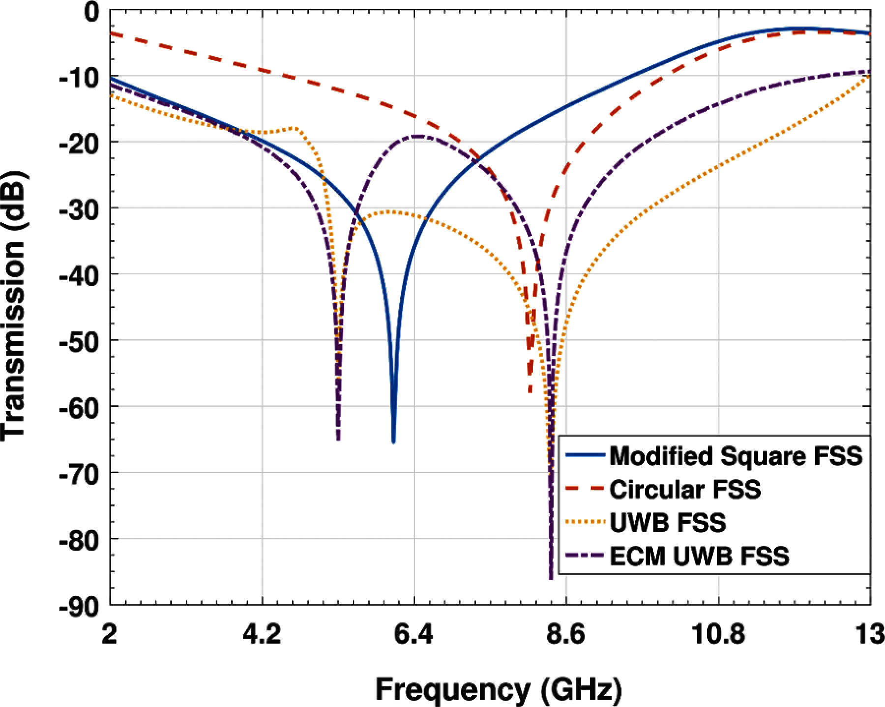
Figure 4: Simulation transmission results of MSLFSS, circular-loop, UWB FSS and ECM UWB FSS for 0° incidence
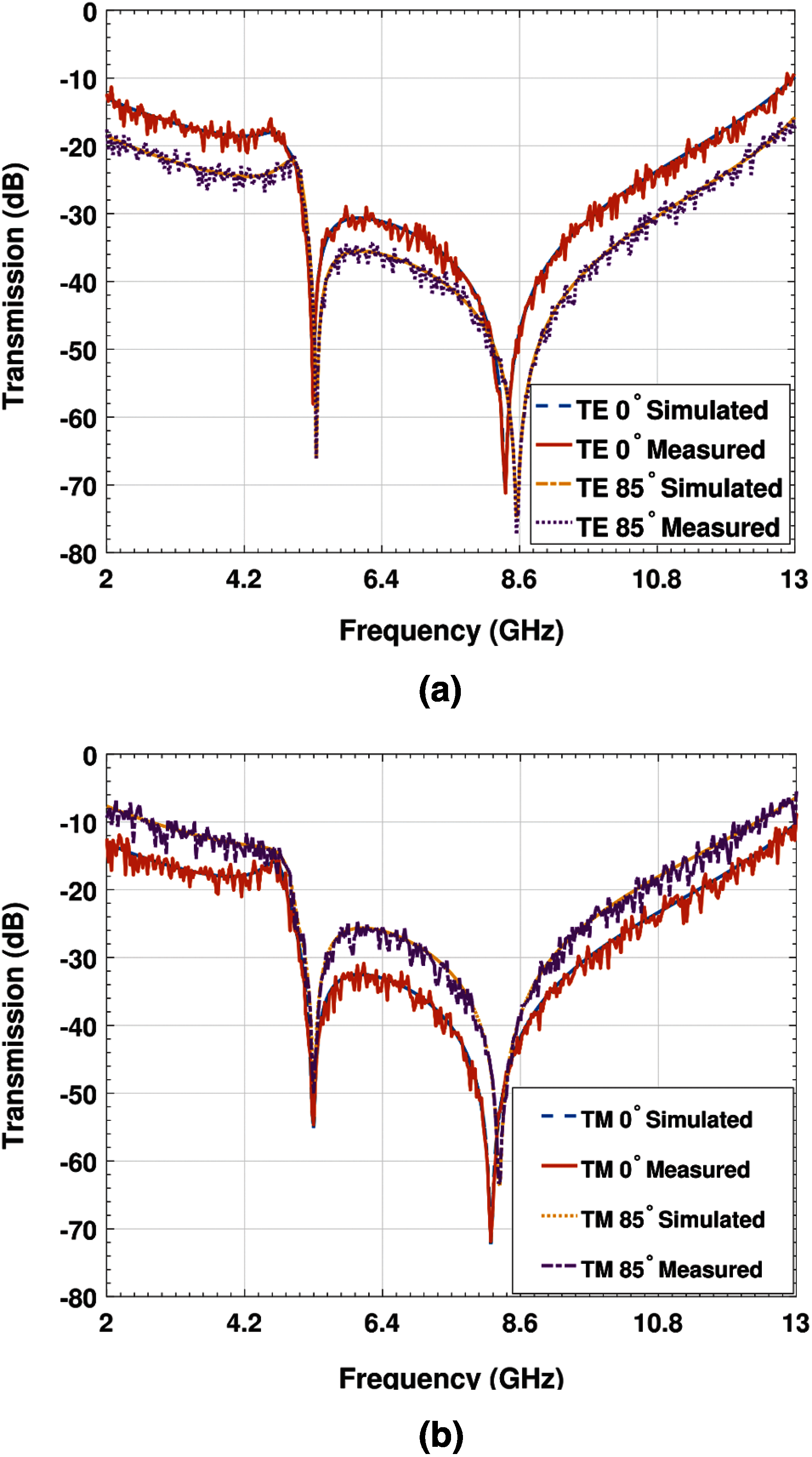
Figure 5: (a) Simulated and experimental results of TE polarization. (b) Simulated and experimental results of TM polarization
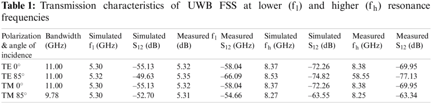
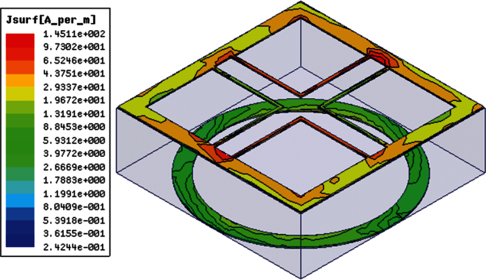
Figure 6: Distribution of electric current on the surface of square and circular element at center frequency 7.5 GHz
3 Performance Analysis of UWB FSS
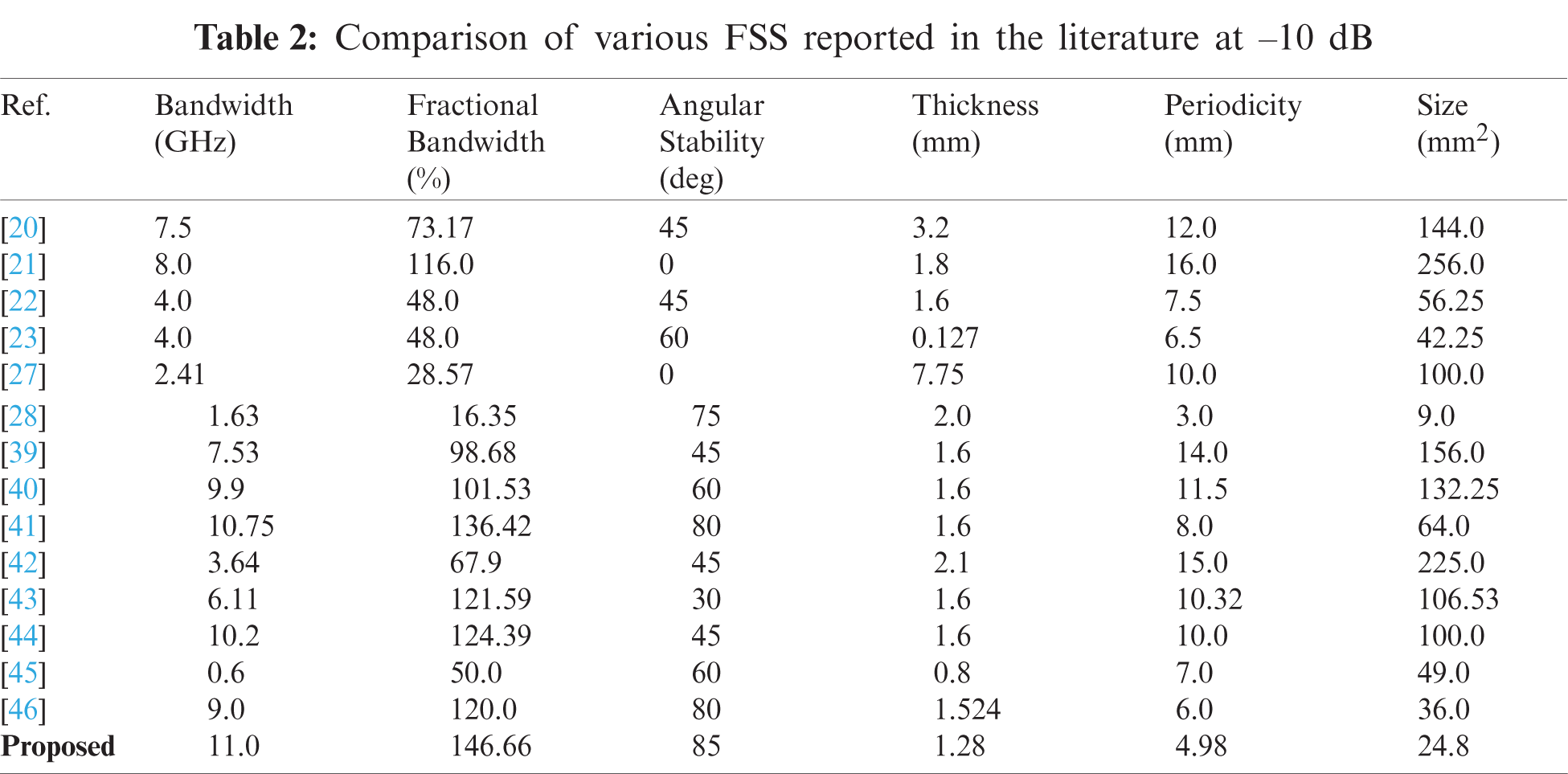
The performance of the UWB FSS has been analyzed based on various parameters such as SE, BW, FBW, dimensions, size, thickness, angular and polarization stability. Tab. 2 illustrates various important aspects of band-stop FSSs which have been explored by different researchers. In Refs. [20–23,27,28,39–46] BWs of 7.5, 8, 4, 4, 2.41, 1.63, 9, 7.53, 10.75, 3.64, 6.11, 10.2, 0.6 and 9.9 GHz with –10 dB attenuations having FBW of 73.17%, 116%, 48%, 48%, 28.57%, 16.35%, 98.68%, 101.53%, 136.42%, 67.9%, 121.59%, 124.39%, 50% and 120%, respectively have been achieved. However, these BWs and FBWs were achieved by compromising on SE, dimensions, thickness, angular as well as polarization stability, as depicted in Tab. 2.
In this research, the efficiency of the FSS has been improved by enhancing the performance of various parameters of the UWB FSS as compared to the designs presented by various authors for communication applications.
For both TE and TM mode, BW has been extended to 11 GHz with FBW of 146%, angular stability is improved to 85°, SE of FSS has been enhanced to more than 10 dB, and better resonance stability has been achieved for UWB FSS as shown in Tab. 2. The miniaturization in dimension and size of unit cell has been achieved by selecting MSLFSS and circular-loop elements and employing them on the top and bottom surfaces of the substrate. The size of UWB FSS is reduced about 82.77%, 90.31%, 57.76%, 41.30%, 75.19%, 84.34%, 81.24%, 61.24%, 88.97%, 76.69%, 75.19%, 49.38% and 31.11% in comparison to [20–23,27,39–46], respectively. Stability of UWB has been investigated and ensured for TE and TM modes up to 85° by reducing the gap up to λ/8 between the adjacent elements and verified through simulated and experimental results. To achieve the flatness in the transmission curve, dielectric slab of RO3210 was placed between the square loop and circular-loop elements as recommended in [10]. The periodicity of FSS unit cell along x-axis and y-axis is 0.12 λ at fc which is 2.44, 3.21, 1.5, 1.3, 2, 2.81, 2.3, 1.6, 3.01, 2.07, 2.27, 1.40 and 1.20 times smaller than the periodicity presented in [20–23,27,39–46], respectively. At 7.5 GHz density of RO3210 is λ/31 which is lesser than λ/4 as established in [21] for multi-layer FSS. The grating lobe or scattering was not experienced because of smaller gap between the adjacent elements making the UWB FSS more consistent for TE and TM excitations at normal as well as oblique incidence. It has been experienced that UWB FSS has achieved angular stability for higher oblique angular incidence. At 0° UWB FSS possesses identical frequency response for TE and TM plane waves due to symmetrical design. However, it is observed that transmission characteristics of UWB FSS are changed for TE and TM excitations as the oblique incidence is increased. The bandwidth of UWB FSS for TE polarized wave is increased and vice versa for TM mode as oblique angular incidence is increased. This variation in the BW happened because the wave impedance of a plane wave is changed for TE and TM due to increase in oblique incidence as investigated by [47–52]. The quality factor is directly proportional to the change in the wave impedance. The wave impedance decreases for TE mode and increases for TM mode as the oblique angular incidence increases. Smaller quality factor for TE mode increases the BW of UWB FSS and larger quality factor leads to smaller BW for TM excitation.
A lightweight and low profile UWB FSS is designed and validated up to 85° through theoretical and measured results. For S-, C-, X- and Ku-bands a bandwidth of 11 GHz is ensured at 10 dB signal attenuation for TE and TM excitations. The proposed FSS with 146% fractional bandwidth is suitable for various applications such as EMI reduction and suppression in radio and aerospace networks. It can also be used to mitigate the effects of electromagnetic waves on the human body and to enhance the radiation characteristics of UWB antennas.
Funding Statement: The work was supported by King Abdulaziz University, Jeddah, Kingdom of Saudi Arabia. M. F. U. Butt would like to gratefully acknowledge the Higher Education Commission (HEC), Government of Pakistan’s financial support through its Post-Doctoral Fellowship Program (PDFP) Grant.
Conflicts of Interest: The authors declare that they have no conflicts of interest to report regarding the present study.
 | This work is licensed under a Creative Commons Attribution 4.0 International License, which permits unrestricted use, distribution, and reproduction in any medium, provided the original work is properly cited. |