DOI:10.32604/cmc.2022.020781
| Computers, Materials & Continua DOI:10.32604/cmc.2022.020781 | |
| Article |
RSS-Based Indoor Localization System with Single Base Station
1Space Science Centre, Climate Change Institute, Universiti Kebangsaan Malaysia, Bangi, 43600, Malaysia
2Department of Electrical, Electronic and Systems Engineering, Faculty of Engineering and Built Environment, Universiti Kebangsaan Malaysia, UKM, Bangi, 43600, Selangor, Malaysia
3Faculty of Mechanical Engineering, Universiti Malaysia Pahang, Pekan, 26600, Pahang, Malaysia
4Antenna and High Frequency Research Centre, School of Electrical & Electronic Engineering, Dublin Institute of Technology, Dublin 8, Ireland
5Department of Electrical Engineering, Division ESAT-TELEMIC, KU Leuven, Belgium
*Corresponding Author: Samir Salem Al-Bawri. Email: s.albawri@gmail.com
Received: 07 June 2021; Accepted: 08 July 2021
Abstract: The paper proposes an Indoor Localization System (ILS) which uses only one fixed Base Station (BS) with simple non-reconfigurable antennas. The proposed algorithm measures Received Signal Strength (RSS) and maps it to the location in the room by estimating signal strength of a direct line of sight (LOS) signal and signal of the first order reflection from the wall. The algorithm is evaluated through both simulations and empirical measurements in a furnished open space office, sampling 21 different locations in the room. It is demonstrated the system can identify user’s real-time location with a maximum estimation error below 0.7 m for 80% confidence Cumulative Distribution Function (CDF) user level, demonstrating the ability to accurately estimate the receiver’s location within the room. The system is intended as a cost-efficient indoor localization technique, offering simplicity and easy integration with existing wireless communication systems. Unlike comparable single base station localization techniques, the proposed system does not require beam scanning, offering stable communication capacity while performing the localization process.
Keywords: Indoor localization; localization techniques; received signal strength
Localization has gained much attention due to its common usage in a plethora of applications, such as asset tracking, navigation, or communication [1,2]. One of the requirements for modern mobile systems is the capability to locate the user’s Mobile Station (MS) [3,4]. Several techniques have been developed for this purpose, offering various accuracies at the price of complexity. A ubiquitous mobile localization system for both indoor and outdoor scenarios, able to track the MS anywhere, is not available yet. Typically, the Global Navigation Satellite Systems (GNSS) only works for outdoor environments with wide geographic coverage. They are widely applied for navigation of vehicles, ships, and airplanes [5,6], however not for indoor applications [7–9]. Meanwhile, the demand for indoor localization in wireless networks becomes significant.
Radio-based localization using Digital Cellular Networks (DCN), Wireless Local Area Networks (WLAN), or Wireless Sensor Networks (WSN) can be implemented for indoor [10] and even underwater [11] environments. The positioning requires a priori knowledge about the Base Stations (BS) locations and typically involves multiple base stations (BS) [12]. The localization performance is affected by the measured signal strength and bandwidth, localization algorithm, and antenna performance [13]. Different complex antennas, e.g., reconfigurable [14,15] or MIMO [16,17] antennas, have been applied for localization systems. For the time of arrival and angle of arrival methods, the synchronization problem and transceivers’ complexity are of key significance [18,19]. Practical implementations of indoor localization involve a Phase Fingerprinting (PhaseFi) system with calibrated Channel State Information (CSI) [20]. It uses an IEEE 802.11n network interface card integrated with multiple antennas. Reported accuracy is 2.8 m or less for 80% of the users. Another method based on RSS [21] estimates MS location by utilizing a certain number of closest neighbors.
In this paper, we propose a closed-form, two-step localization technique for microcell and femtocell applications. The developed algorithm is the RSS-based solution for indoor localization. It can operate with a single base station and–unlike solutions in [14,16]–it uses a simple non-reconfigurable antenna. The technique estimates the angle and distance from the Base Station (BS) using signal strengths of direct (i.e., line-of-sight, LOS) and reflected (i.e., non-line-of-sight, NLOS) signals while relying on second-order equation harmonic analysis. The technique is validated in a real-life scenario in an open-plan office space with furniture and demonstrates improved accuracy of 0.7 m or better for 80% of users’ positions.
Nowadays, the accelerated development in wireless communication systems including extensive usage of smartphones led to accelerating smartphone technology-based localization. Concerning indoor localization techniques, several techniques have been reported with different achieved accuracy such as 1.5 m in [22] which requires fingerprinting, 2.4 m in [23] which has no information provided about latency and scalability. Furthermore, the indoor pure fingerprint method in [24,25] utilized the collected data from the smartphone geomagnetic data. Nevertheless, the accuracy of fingerprinting-based indoor localization is limited, and the demand for additional data from other sensors is highly required to increase the accuracy. To elevate the indoor localization methods performance, the fingerprinting method has been used with other technologies such as additional nodes and Wi-Fi. For instant, Wi-Fi aided to enclose the search of space with extensive help from surrounded access points (APs) which improve the accuracy of fingerprinting [26].
RSS has been recorded and processed at multiple base stations positioned to provide overlapping coverage in the area of interest. By enabling a smartphone camera to capture the extremely weak and high-frequency features, a light LiTell scheme is implemented to analyze the signal strength variations in different sites followed by identifying users’ location [27]. The drawback is however that this process is labor-intensive and time-consuming. Horus algorithm is proposed in [28] by utilizing a probabilistic technique depending on RSS. In [29] CSI is utilized to reduce the instability of RSS values for indoor localization. In [30] an improved Wi-Fi indoor localization was proposed based on the collaboration of several assistant nodes and fingerprint algorithm (dubbed CFAN). Around 4.3 m accuracy was achieved for 80% of the users. In [31] a curve fitting (CF) method using RSS was proposed. Two localization search algorithms have been suggested, however, the localization accuracy was improved by 20% compared to traditional fingerprinting. A normalized magnetic field data in [32] has been used for indoor localization to overcome the heterogeneousness device by utilizing multiple neural networks. Thus, the neural networks have been applied to collect the truth points data at the ground while estimated positions are exhibits using the user collected data. An indoor positioning method is given in [33] to overcome the issue of device dependence within 5 m accuracy.
For the abovementioned reasons, our target to propose a method which can increase the accuracy without relying on additional devices by utilizing only single base station.
The radio propagation links are observed between the Single Base Station (SBS) transmitter and various Mobile Station (MS) receivers. Each link allows for observations of indoor received power prediction from direct beam and delayed reflected signals due to a multipath propagation environment. The proposed ILS system is based on the equations of direct waves and multiple reflections from the walls when the dimensions of the area are known. This allows for a fast algorithm with high geometrical resolution as follows:
1) The investigated scenario consists of M receivers located on an i by j grid in xy-plane and a single BS transmitter at their actual known coordinate locations as follows:
where, M represents the number of MSs whereas, i and j represent grid indexes along with x and y coordinates, respectively.
2) Several segments called reflection points (RP) in 2D Cartesian coordinates are considered for each wall inside the room. The reflection points are represented in Cartesian coordinates as RP (y, z) for north and south walls and RP (x, z) for east and west walls.
3) The length of direct path d, i.e., Line-Of-Sight (LOS), is calculated and the initial incident angle α is defined for each MS as shown in Fig. 1. Due to fixed height z, the angles α between BS and each MS is calculated as:
where dz is the distance along the z-axis between the MSs and SBS.
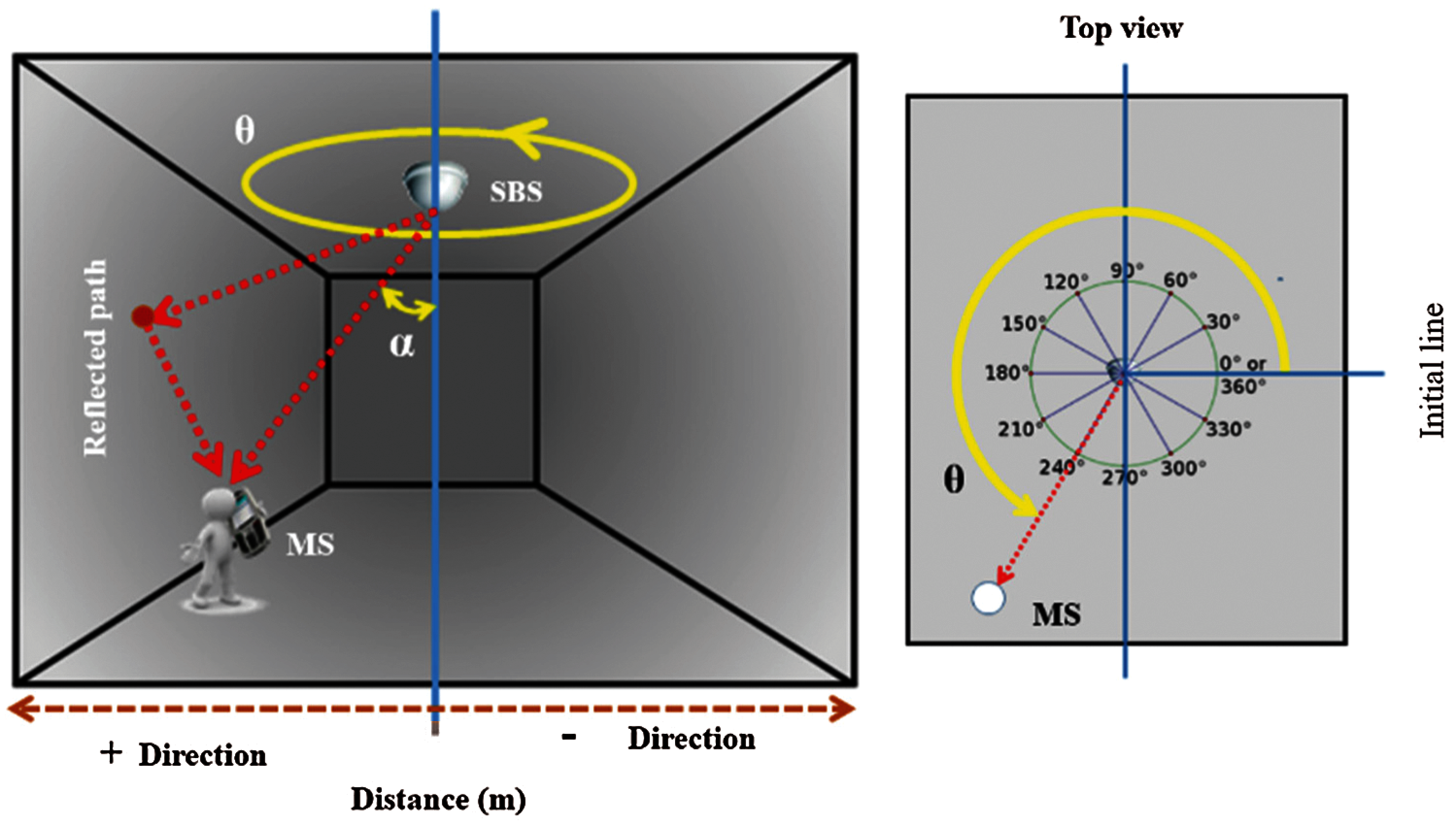
Figure 1: Principle of the proposed indoor localization technique
4) The first-order random reflected signal from the room’s walls is calculated by finding appropriate reflection points (RP) in the wall, as outlined in Fig. 2. Every two opposite walls have the same number of RP, where the calculated distances are considered in (x, z) and (y, z) planes. The distance traveled by the incident ray (i.e., SBS to RP) will be denoted as dR1 and the distance traveled by the reflected ray (i.e., RP to MS) will be denoted as dR2, while the total NLOS path distance is their sum denoted as dNLOS.
The incident angle (β1) and reflected angle (β2) of the propagated rays are then calculated in (4), following Fig. 2.
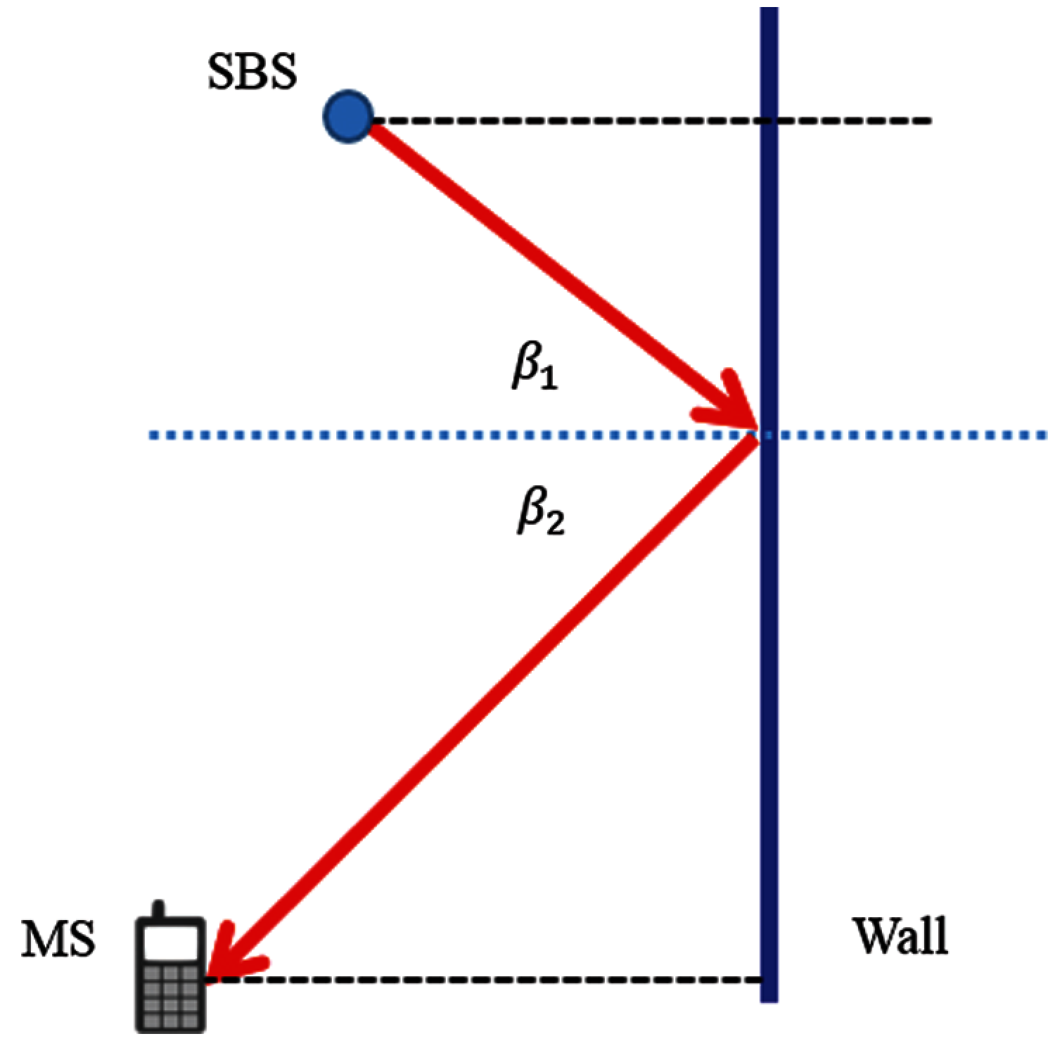
Figure 2: Principal of propagation ray, incident, and reflected angles
The matrix in (5) shows the NLOS distances of reflected signals from the whole walls, where each column represents the distances for the same RPs for different MS. Moreover, the minimum value of the nearest RP along each column is calculated to get a raw vector of minimum distances for the shortest possible NLOS path length.
5) Using Friis equation, the LOS power can be calculated as follows [34,35]:
where PT is the power supplied to the transmitter antenna, GT and GR are gains of transmitting and receive antennas, λ is the wavelength, dLOS is the LOS distance between the transmitter and the receiver, γ is path loss exponent. For NLOS, the average reflected power PR (Ref) is assumed to be the extended path length of free space value multiplied by the square of the reflection coefficient of the wall [36]:
6) The MS location can be estimated via measured distance and angle once with the assumption of a priori knowledge of the room geometry. Steps 1–4 are used to find the theoretical RSS power. Therefore, if the received power is measured, we can calculate the estimated distance between the SBS, and MS’s as follows:
As shown in Fig. 3,
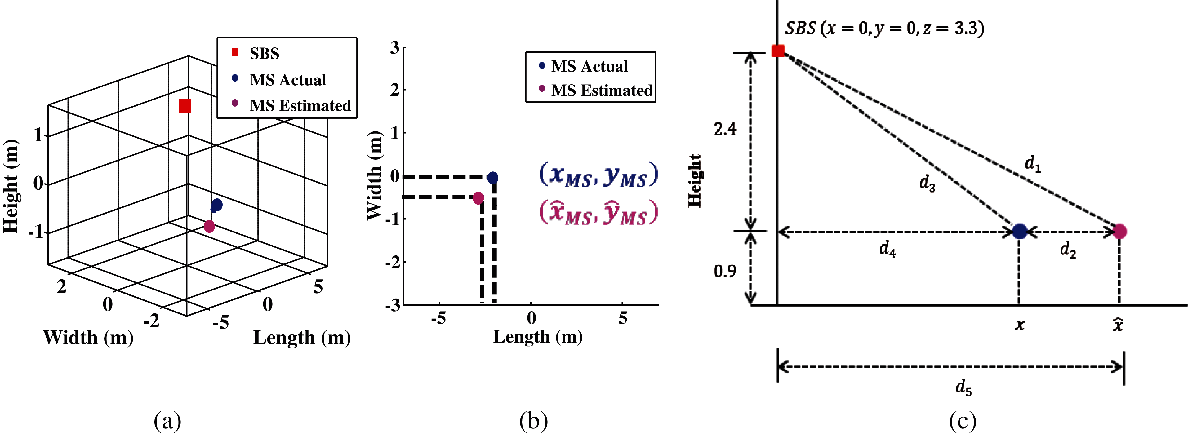
Figure 3: Representation of estimation and actual mobile location in (a) 3D x, y, z plane (b) 2D x, y plane and (c) 2D x, z plane
Eq. (24) is second order, which is solved to calculate
where m indicates the number of MS. The flow chart in Fig. 4 explains the algorithm.
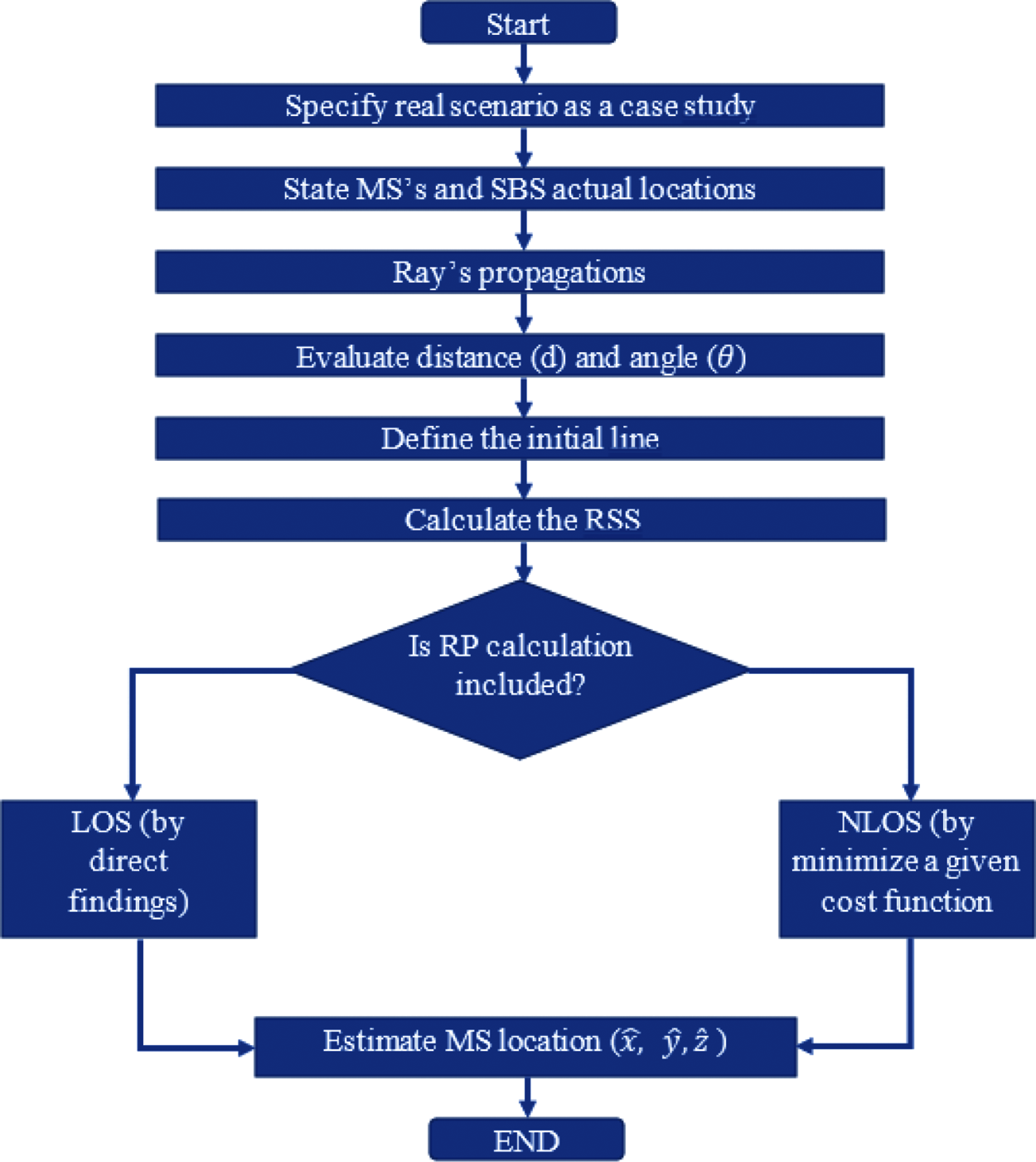
Figure 4: Proposed algorithm
Fig. 5a shows the measurement setup used to measure and analyze variations of Received Signal Strength (RSS) between the SBS transmitter and MS receivers at different positions. As the test environment, an office of ACE center building (UniMAP university) was chosen. The algorithm evaluated in this paper is implemented and executed to estimate the unknown mobile station receiver positions with the Single Base Station (SBS) mounted at the center of the room’s ceiling. The collected RSS is processed using MATLAB software. All experimental data are collected at a Wi-Fi 2.4 GHz frequency.
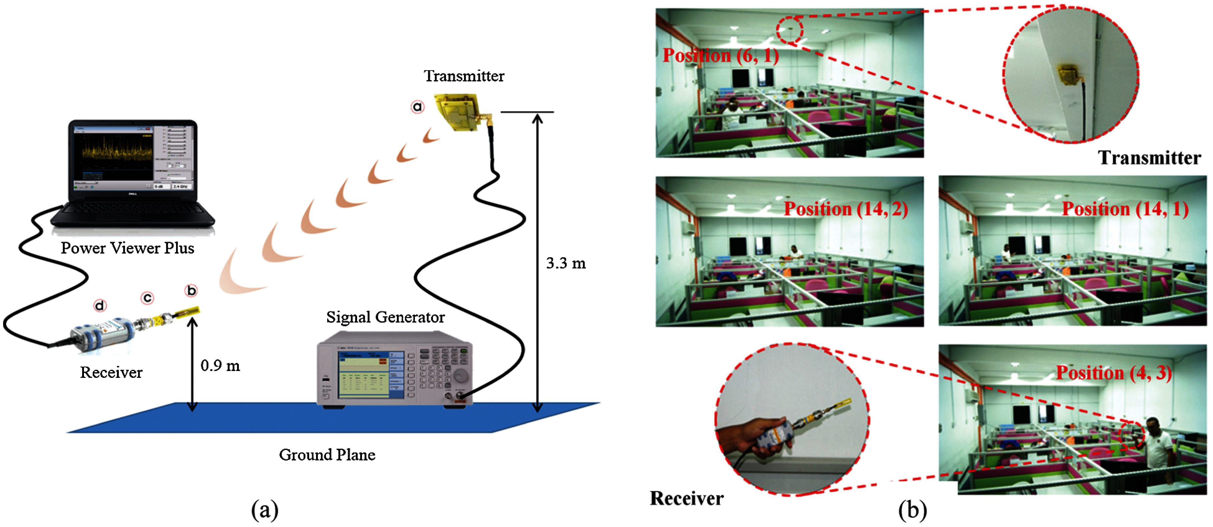
Figure 5: (a) RSS indoor measurements setup, (b) ILS RSS data collection procedure with the position of x- and y-axis
The experimental setup is considered using parameters listed in Tab. 1 whereas antennas reported in [37,38] have been used for transmitter and receiver, respectively. Twenty-one positions have been chosen to collect the real-time RSS followed by characterizing the data in terms of the proposed algorithm. The setup can be seen in Fig. 5a, whereas Fig. 5b shows the data collection procedure.

The measured RSS data, as well as the theoretical RSS, is calculated in the same scenario based on the following parameters:
• Room: width (y = 6 m), length (x = 15 m), height (z = 3.3 m).
• SBS location: (x = 8 m, y = 3 m, z = 3.3 m) at the center of the room.
• Number of users (MS) = 21.
• MS height (z = 0.9 m).
• MS actual location (x, y).
6 RSS Based Indoor Localization
The proposed procedure consists of three steps: firstly, data are collected, followed by analysis and localization. The RSS measurements were obtained using in-house fabricated terminals, as shown in Fig. 5. To validate and properly map the RSS, the actual MS position has been calculated on two grids, consisting of 21 and 361 points, distributed in (3
Furthermore, solid concrete material was used as walls material with a reflection coefficient of 0.35 at 2.4 GHz [39] during the RSS data analysis and calculations. The theoretical received power is calculated in this study, which is based on the dimensions and properties of the office of Advanced Communication Engineering (ACE) Centre at UniMAP, which was used for the measurement campaign. Two categories are considered for collecting the data:
• Direct path, line of sight (LOS)
• First-order reflection from walls
Fig. 6 shows the theoretical 2D and 3D reflected RSS values for each wall in the tested (3

Figure 6: Map of office space used for testing, (a) 2D, (b) 3D
Ninety-eight RPs have been accounted for in the east and west walls (parallel to x-axis) and forty-two RPs for the south and north walls (parallel to y-axis). At each point, a part of the signal reflects from the wall and the other part penetrates it. The received power has been calculated using (7) for each RP based on the reflection coefficient of the wall’s construction material and both incident and reflected angles.
The 3D representation of the RSS in Fig. 7 shows how received power decreases and distributes as the distance from the transmitter to the wall and then to the MS increase. It can be seen clearly that a stronger reflected signal is computed in the points near a wall, while rapidly weakening once MS moves away from the walls. Therefore, we can observe that the obtained RSS by the receivers is not concentrated in a specific direction. The maximum calculated power is −43 dBm whereas−58 dBm is the minimum power for south and north walls. However, −35 and −50 dBm are observed as the maximum and minimum received power for west and east walls.
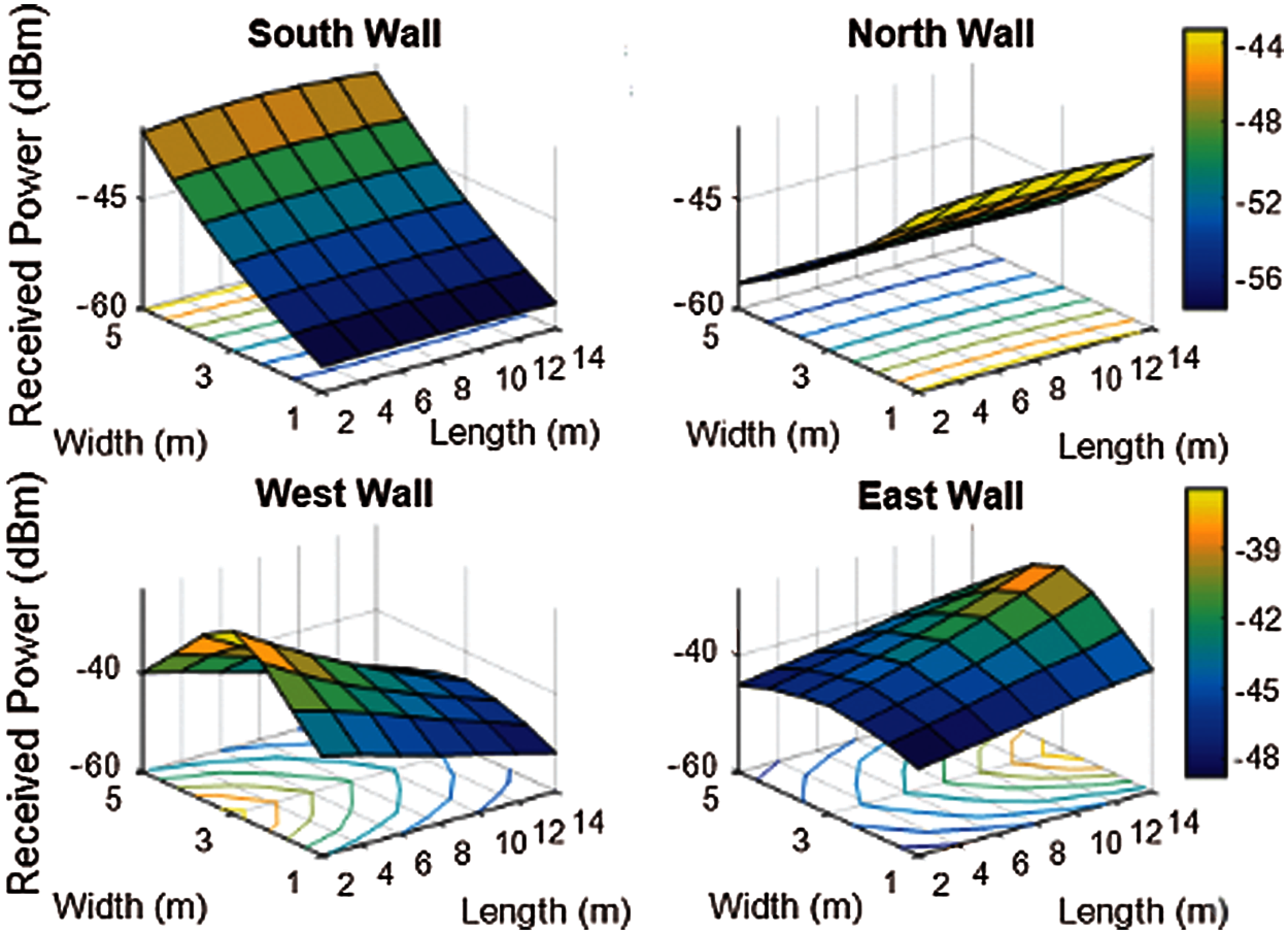
Figure 7: 3D RSS plots from walls for (3
LOS direct path, NLOS reflected path and the overall estimated 3D RSS received power for (19
Tab. 2 shows the median
A threshold level has been allocated to –70 dBm to ensure that Wi-Fi signal strength at 2.4 GHz is above its required threshold level [40]. Therefore, the measured received power is shown in Fig. 10 where transmitter-to-receiver distance changes from 2.4 and 6.8 m. It can be seen that the predicted received power from the proposed prototypes remains above the threshold value.

Figure 8: 3D plot of the theoretical received signal strength within (19


Figure 9: Measured RSS plots in (3
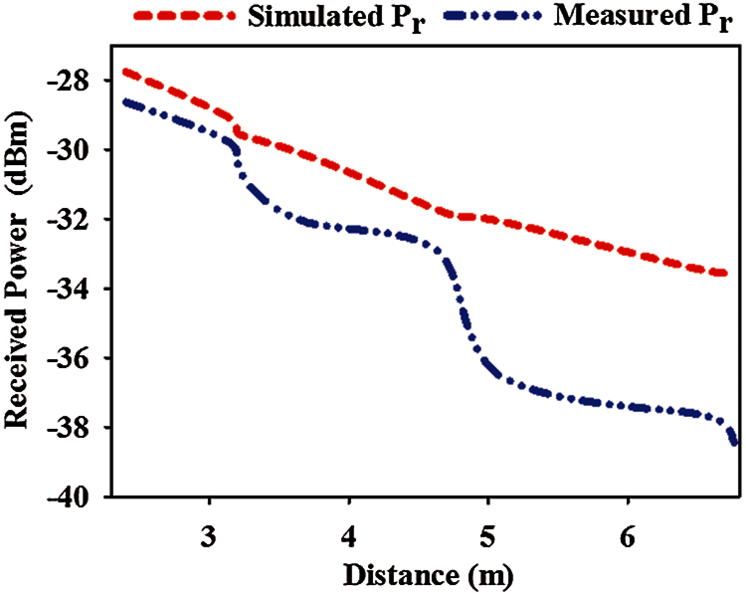
Figure 10: Simulated and measured RSS in the indoor environment for different setups
To validate the proposed algorithm, triangulation combined with (33) is used for localization within the room. Fig. 11a displays the CDF of estimated distance error for 21 MS locations. 85% of MS are located with accuracy better than 1.08 m. Furthermore, 70% of the MSs can be identified in less than or equal to 0.8 m error.
For the angle estimation, 20 MS locations (96% of the total users) exhibit an error not exceeding 5 degrees, as shown in CDF plot in Fig. 11b. Tab. 3 shows the median
The developed indoor localization system could be used by most of the future generation network subscribers as an alternative technology with an accurate, safe, and reliable mechanism to identify the MS location especially in emergency call situations whether to prevent accidents/fire in large warehouses, help shoppers in a mall…etc.
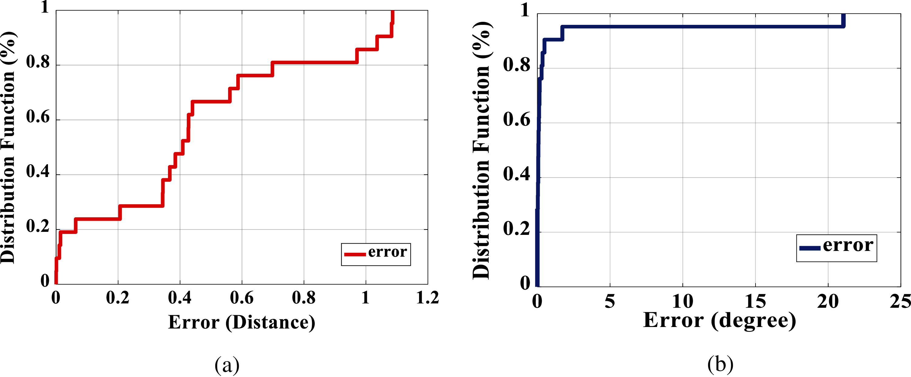
Figure 11: CDF for MS estimated indoor environment in (a) distances (b) angles


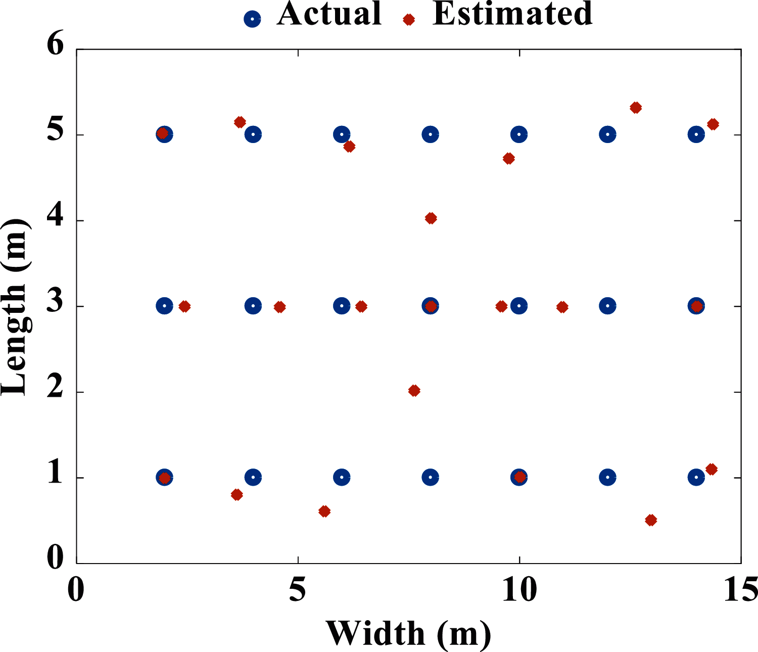
Figure 12: Actual and estimated MS coordinates
In this paper, a localization algorithm for indoor application has been proposed which utilizes RSS data and a single base station. The location is calculated by using direct and reflected signals. The proposed algorithm is validated with experimental data. It is demonstrated that 80% of users are localized with an error below 0.7 m. Furthermore, the angle error is <5° for 96% of the users. The experimental results show that the proposed localization technique can be implemented using only RSS and a single base station with a simple, omnidirectional, and non-reconfigurable antenna. The proposed algorithm might be used for localization in micro- or femtocells for next-generation wireless networks.
ILS broadly exists to provide services depending on a user’s location in various categories including tracking, healthcare, and navigation. Furthermore, upcoming research will be foreseen to be focused on the implementation of the proposed indoor localization technique in five generation (5G) technology using a unique massive MIMO antenna array integrated with the proposed algorithm as an ideal platform for realizing estimated high accuracy will be considered.
Acknowledgement: The authors acknowledge with thanks to Universiti Kebangsaan Malaysia and Universiti Malaysia Perlis for technical and financial support.
Funding Statement: This work is supported by Climate Change Institute, Universiti Kebangsaan Malaysia.
Conflicts of Interest: The authors declare that they have no conflicts of interest to report regarding the present study.
 | This work is licensed under a Creative Commons Attribution 4.0 International License, which permits unrestricted use, distribution, and reproduction in any medium, provided the original work is properly cited. |