DOI:10.32604/cmc.2022.020529
| Computers, Materials & Continua DOI:10.32604/cmc.2022.020529 | |
| Article |
Dual-Port Content Addressable Memory for Cache Memory Applications
1Department of Computer Engineering, Near East University, Nicosia, N. Cyprus via Mersin-10, Turkey
2Computer Systems Engineering, Arab American University, Jenin, 240, Palestine
*Corresponding Author: Allam Abumwais. Email: 20177286@std.neu.edu.tr
Received: 28 May 2021; Accepted: 15 July 2021
Abstract: Multicore systems oftentimes use multiple levels of cache to bridge the gap between processor and memory speed. This paper presents a new design of a dedicated pipeline cache memory for multicore processors called dual port content addressable memory (DPCAM). In addition, it proposes a new replacement algorithm based on hardware which is called a near-far access replacement algorithm (NFRA) to reduce the cost overhead of the cache controller and improve the cache access latency. The experimental results indicated that the latency for write and read operations are significantly less in comparison with a set-associative cache memory. Moreover, it was shown that a latency of a read operation is nearly constant regardless of the size of DPCAM. However, an estimation of the power dissipation showed that DPCAM consumes about 7% greater than a set-associative cache memory of the same size. These results encourage for embedding DPCAM within the multicore processors as a small shared cache memory.
Keywords: Multicore system; content addressable memory; dual port CAM; cache controller; set-associative cache; power dissipation
The microprocessor that contains multiple cores (processors) in a single integrated circuit (IC) is named as multicore [1]. Manycore processors are multicore processors that designed for a high degree of parallel processing containing numerous processor cores. In multicore and manycore processor systems shared memory has the key role for providing efficient communication between the cores. When multiple cores try to access the same shared memory at the same time, it may cause hazard. There are many studies in the literature to improve the performance of shared memory. Reducing access latency and power consumption are the main directions to improve the efficiency of the shared memory. Improvements in cache architecture and cache replacement algorithms are two options to pursue in this direction.
Most multi/many core systems use associative memory (AM) cache as a shared memory [1,2]. Enhanced cache architectures aims to empower the parallel search and rapid access [1,2]. On the other hand, replacement algorithms are used to help the cache controller choose which data to discard to make room for the new ones [3,4]. In addition, an efficient replacement algorithm will improve the cache access latency. Content addressable memory (CAM) is similar to direct-mapped AM that refers to memory whose locations are accessed by comparing tags (part of contents) rather than providing their addresses [2], and has some features to be used as a shared memory [2,5,6].
This work presents a special purpose shared memory architecture based on content addressable memory and a replacement algorithm. The main purpose of this work is to allow simultaneous access to the cache memory by multicore processors that achieve more efficient access latency with various CAM cache sizes compare to set-associative cache.
The rest of the paper is organized as follows. Section 2 gives briefly the literature review related to CAM and shared cache in multi-core systems. Section 3 presents the architecture of the proposed dual port CAM (DPCAM) and the Near-Far Access Replacement Algorithm (NFRA). Section 4 shows the implementation of the DPCAM in Field Programmable Gate Arrays (FPGA), discusses the functional and timing simulation and illustrates the power estimation analysis. Section 5 represents the conclusion.
In multicore processors, there are multi-level of caches and most of them are set-associative [1]. Shared level is usually shared across the cores and is placed on the system chip [1,4]. Various types of AM and CAM have been designed and implemented on the FPGA to be use on special purpose applications. However, some of these works [7–11] suffers from memory efficiency due to the limited size, update latency, power cost and low density and etc. Thus, they could not be used as shared level of cache in modern multi-core system [12]. There are several works on two approaches to improve memory efficiency by an architectural design [8,13–15] and by efficient cache replacement algorithms [16–20].
Resistive configurable associative memory (ReCAM) is used to solve some of the issues. ReCAM improves the access latency by limiting the load/store fatigue at the beginning of executions [13]. ReCAM uses hamming distance algorithm which searching the nearest cell for reading and writing. It exploits this feature to design a memory with better efficiency in both performance and power consumption. In ReCAM architecture, the processing element has two kinds of execution units: the first is composed of ReCAM arrays where memories are connected using a crossbar. The second is a traditional core. The main disadvantage of this design, it was implemented on single processor system and not suit on multi-core systems. Whereas the DPCAM purpose to be used in multi/many-core processors.
AM architecture using Virtex-6 FPGA series inside the cache controller was presented that was designed to work as a look-up table inside the cache controller with size of 1KiB and a block size of 16 byte [14]. The simulation results show that the cache controller's setup latency is 1.66 ns and total power consumed is 5.53 mW. The main disadvantage of this design is that difficult to scale it to a bigger size. Therefore, it cannot be used in shared memory.
The design called Gate-based area efficient ternary content addressable memory (G-AETCAM) which uses flip-flops as FPGA storage elements and it can be configured as binary and ternary CAM where gate levels reduce the resources on FPGA [6]. The design has been implemented in different sizes for the Virtex-5,-6 and-7 FPGA series. The performance is increased by 28 percent compared to the other FPGA-based Ternary content-addressable memory (TCAM). It also facilitates better scalability than other TCAMs due to less complexity of the architecture. In [15], the authors presented an efficient FPGA resources and power consumption called Zi-CAM. It has less complexity and power consumption than traditional RAM-based CAM designs on FPGAs. The internal structure consists of two main units: RAM unit and lookup tables unit. Each unit is activated according to the sequence of data. The design has been implemented on Virtex-6 FPGA. The presented results showed that Zi-CAM improved FPGA resources cost, power consumption and update latency when compare to common FPGA-based CAMs. The main benefit is update latency of Zi-CAM is nearly constant with different sizes. These two designs have attractive features for networking applications with limited size especially in routing table. However, it is difficult to implement as shared memory in multi/many-core system.
In [8], the author presented a logic-based high-performance BiCAM architecture (LH-CAM) with Xilinx FPGA. Multiple data may be written simultaneously if enough I/Os are available on the FPGA device; therefore, improving writing latency. It also provides faster updating algorithms but the complexity linearly increases with the CAM depth and hence access latency will increase linearly.
The second approach to improve memory efficiency is to use efficient cache replacement algorithms. Least Recently Used (LRU), random, Round Robin, and modified LRU are commonly used. Many other advanced strategies have been proposed, most of which are based on LRU to solve the miss rate and access latency issues and are designed for general purpose applications rather than multi-core processors [16]. On the other hand, few of researches were touched to evaluate the multi-core system performance associated with these types of replacement algorithms. In [17], the authors presented a Least Error Rate (LER) replacement algorithm in shared cache L2 with minimum error rate in writing. LER modifies the algorithm used to store incoming data in a cache line with minimum write error rate. To accomplish this, LER compares the incoming data with the contents of the set lines simultaneously. The experiment's results of these algorithms were compared to LRU and show 1.4% improvements on miss rate and 3.6% less overhead. A new Random First Flash Enlargement (RFFE) had been proposed [18]. It enhances the overwriting on L2 shared caches when a cache line should be replaced depending on a random Gaussian-coding scheme. This replacement algorithm increases the complexity of the cache controller.
In [19], a new update algorithm was proposed; it focused on designing a high-speed intelligent update algorithm for a RAM-based TCAM because it is the main factor that affects power, performance and scalability in TCAM. The design was successfully implemented on Virtex-6 FPGA series. The results show the functional simulation of the design where the authors prove that their design consumed less latency for updating the blocks. Authors in [20] have successfully designed another updating technique based on RAM-based TCAM, which automatically adds incoming data and delete old one whenever the TCAM become full. The main disadvantage of these two algorithms is the complexity especially when increase the memory size and hence consumes large power.
Moreover, it should be emphasized that all of the previous replacement algorithm add a new overhead of accessing data and increase the non-computational times to update the location because they do not utilize cache hardware architecture.
The main function of the cache replacement algorithm is determining the effective response of the cache. Although the replacement algorithms goal is to erase the block that will not be accessed in the near future, some of the erased blocks will be accessed in the far future while executing instructions. The data written on the shared level of cache can be divided into two versions. Near-access data may be used by near coming instruction and far-accessing that will be accessed, relatively, long time after being written. The far-accessing data stored in a line could be overwritten before used. In most cases, the controller can produce far-access operation such that the interested core/s read them from lower level and write them in their private caches [1,14].
The goal of this work is to improve the cache access latency by designing a standalone memory that can be used in multi-core systems as a shared pipeline cache. For the pipeline processors usually dual port is used to avoid stalling during simultaneous access to the memory [21,22]. The proposed design is based on dual port CAM (DPCAM), which provides simultaneous write and search operations within the CAM memory, if more than one core try to access the memory. In addition, NFRA is proposed and implemented as a hardware component inside DPCAM to reduce the cost overhead and the complexity of the cache controller.
The proposed DPCAM works as a standalone pipelined shared cache where one port is used for writing and the other one is used for reading. The DPCAM includes dual port: DS31-DS0 for writing and Dd31-Dd0 for reading, Tag Field, Data Field, Control Unit, and comparator (CMP) as shown in Fig. 1.

Figure 1: DPCAM design
In the stage of store back (SB) the core provides the Data source [Ds31-Ds0] and the Tag source [Ts15-Ts0] to be written on a selected cache line. In the stage of Operand fetch (OF) the core provides the Tag destination [Td15-Td0] to be compared with all cache lines simultaneously and the stored data from the Data Field will be read to the destination data bus [Dd31-Dd0]. This two ports works concurrently.
Each cache line (L) is composed of two fields: the Data Field and the Tag Field and is associated with a simple 2X1 comparator (CMP). Data Field contains the shared data to be stored while the Tag Field contains a unique tag (a part of data plus version number) for each Data Field. The length of each field depends on the architecture in which the CAM is used. The tag field can be varied to suit the number of shared unique data versions, e.g., 32-bit tag can accommodate up to 4 Giga versions of data. The CMP is needed in read operations. It compares the tag coming from the OF stage [Td15-Td0] with tags stored [Ts15-Ts0] in cache lines.
Another main component of the DPCAM architecture is the Control Unit. It has two functions, controlling the write operation and implementing the replacement algorithm. The Control Unit of the DPCAM includes a pointer to produce an active high Latch Enable (LE) signal for each memory line on a rotating basis. Fig. 2 depicts the architecture of Control Unit. The control circuit can be employed to select the location where data will be stored where locations are selected sequentially for writing with simple overwriting techniques to update the contents and erase the old one. A set of D Flip Flop (D-FF) is used that is equal to the number of locations, the output of each D-FF points to the corresponding DPCAM location. When the system is reset, this pointer points to the LE0 first memory location, so that the first writing operation will be performed on line 0 of the memory. After writing to the current location, the pointer points to the next location, and so on until location n − 1 (Ln − 1).
The writing operation in DPCAM is controlled by the Control Unit and the WR signal on the write port. The stage SB of writing a core provides the data [Ds31-Ds0], the tag [Ts15-Ts0] and the active low WR signal. On the negative edge of WR signal (the end of WR), the control circuit moves the LE to LE1 in preparation for the next writing which will be to line 1. The read operation occurs when the stage OF of the reading core applies the tag destination [Td15-Td0] and an active high read (RD) signal to all Tag Fields simultaneously. The RD signal outputs the stored source tags to the CMP of each memory line in order to be compared with the applied tag simultaneously. If a match occurs, the equality signal of the comparator is used as an output enable (OE) signal which outputs the stored data from the Data Field to the destination data bus [Dd31-Dd0] where it can be read by the OF unit of the reading core. In case of reading and writing to the same memory location, the Control Unit will give priority for writing and will give a WAIT signal to the reading operation. In case of reading and writing to the different memory locations simultaneously, both read and write ports operate concurrently, which significantly reduce a cache access latency. The stage SB of the writing core provides the data [Ds31-Ds0] and the tag [Ts15-Ts0] which are written to the location determined by the Control Unit. On the other hand, the stage OF of the reading core provides the destination tag [Td15-Td0] and RD signal to all tag fields simultaneously and the stored data from the Data Field can be read to the destination data bus [Dd31-Dd0].
In the DPCAM, a replacement algorithm called NFRA based on simple hardware units is implemented. In the proposed architecture, as an alternative solution to reading the data from lower level memory by the cache controller which increases the access latency, new small DPCAM is implemented. The main DPCAM contains the near-access data, while the new module is used for the far-access data, as shown in Fig. 3. Certainly, because the modules of the far-accessing are less frequently used, it will be smaller than those of the near-access. For example, with four cores and 64 Kbyte (KiB) shared DPCAM, each core can write 2k operand, each includes eight bytes of data and tag, to the DPCAM before it needs to be overwritten.
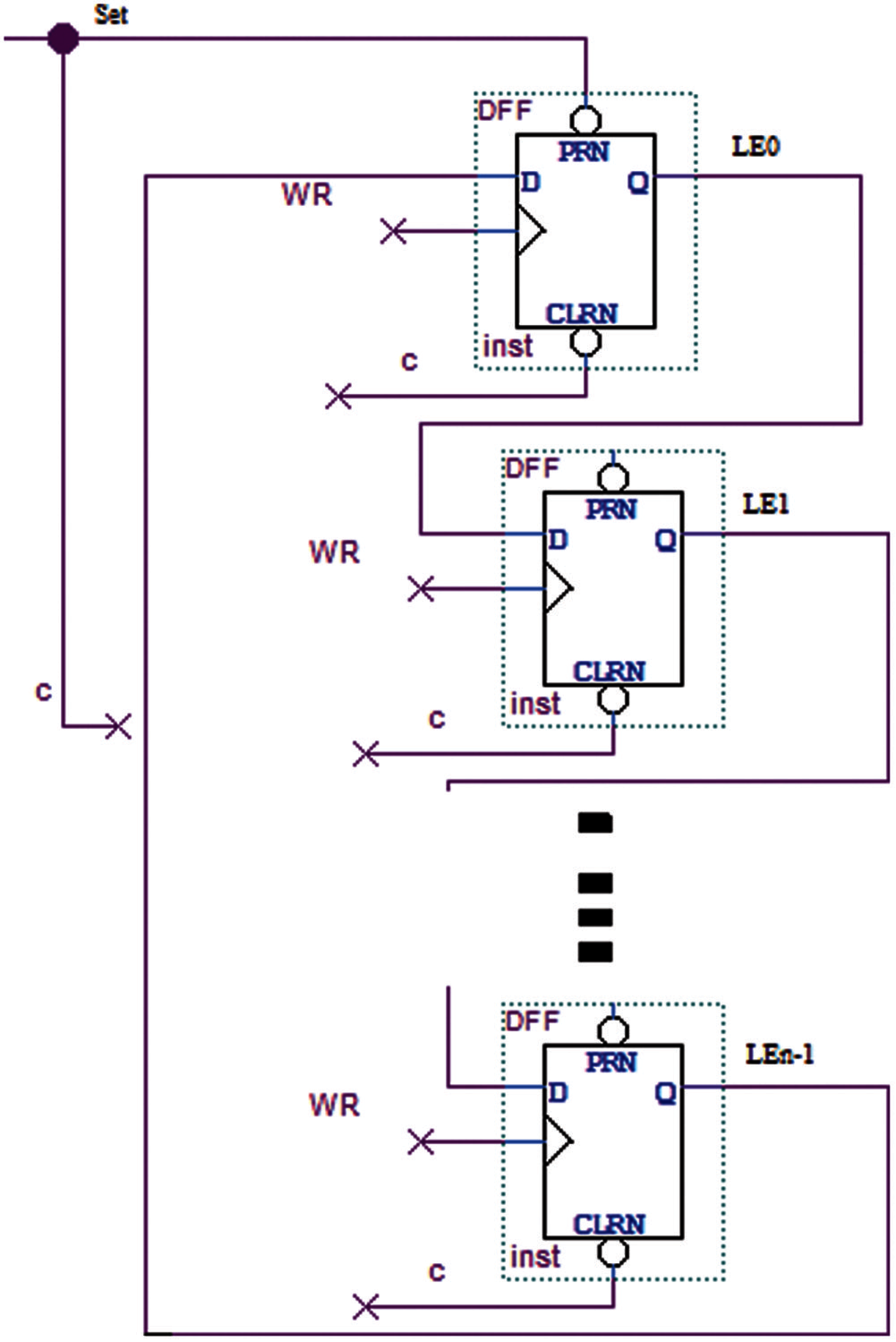
Figure 2: Control unit
Referring to the Control Unit and writing through the pointer which is the main parts of the NFRA, if the processor writes to location Lx, the next instruction will write its operand on location Lx + 1. This process can be repeated until location Ln − 1 is accessed, after which it moves back to LE0 where it starts overwriting the old data and tags. This technique is applied in both near-access and far-access module. It can be noted, that the NFRA can be implemented on the hardware level with less cost and less access overhead in compiler computation. The cost overhead is mostly related to the cache controller complexity and its latency. As a new solution, the proposed NFRA is implemented using simple hardware inside DPCAM control unit instead of a complex algorithm installed inside the cache controller, thus NFRA improves the cache access latency. Using an algorithm at compile time allows separating the near-access and far-access to be stored/loaded in/from different DPCAM modules [1]. The far-access module works on demand. In other words, it gets activated if any core needs to access it for storing/loading data. Other than that blocks are transferred to a new inactive mode. This is a well-known concept in caches called the migration principle to save the power consumption [23,24].

Figure 3: Near-access, far-access DPCAM modules
DPCAM has been implemented, compiled, simulated, and verified using Quartus prime pro 19.1 that includes ModelSim package for design and simulation supported by Intel [25]. DPCAM has been built and evaluated as a standalone memory using Intel FPGA family Cyclone V with 28 nm technology [26]. This is the first step to demonstrate that DPCAM can replace the shared cache in the memory hierarchy of a multi-core processor. For testing DPCAM two cores was used to assess the latency of read and write operations. DPCAM has been implemented by both block schematic files and Verilog HDL code. Files have then been verified and debugged using ModelSim and Vector Wav File (VWF) in both functional and timing simulation. A special tests were written to simulate and observe the latency of reading and writing operations of DPCAM. In addition, the Power Analyzer Tool has been used to estimate the static and dynamic power consumption of DPCAM. The performance of DPCAM was compared to the set-associative cache which is the most popular architecture type used as shared memory in multi-core systems [1,2].
During the functional simulation the following tests to assess the performance of DPCAM were accomplished: write and read operations, the simultaneous read and write operations into the different memory location and the simultaneous read and write operations into the same memory location.
The test-bench program starts by resetting the control unit. It then generates random 16-bit tags and 32-bit data and puts them on the input pins to perform the write operation. After that, it keeps generating a repeated read/write signals until the end of simulation time. It finally puts the 16-bit tagd to the input pins in order to compare with stored tags and output the data to the output pins to perform the read operation. The test-bench is used for functional simulation in DPCAM. Moreover, it is used for DPCAM which uses NFRA and set-associative cache which uses LRU replacement algorithm in order to compare them in terms of latency and power dissipation. The diagram in Fig. 4 illustrates the use of the test-bench program, which is a special benchmark program that was written for analysing the latency and power dissipation assessments for all read and write cases.

Figure 4: Test-bench program
Fig. 5 shows a thumbnail image of several clock cycles (clock period equal 10 ns) for reading and writing to the 64 KiB DPCAM. In the first interval (0 to 10 ns), the control unit was set to start pointing on the first location. Instantly when the write (WR) signal goes down, because it operates on negative edge, the written data (outI) appear clearly on the DPCAM locations. This means that the input values have been stored in the targeted DPCAM locations. In the second interval (10 to 20 ns), the processor retrieves the data that is stored in DPCAM location, it loads the corresponding tag (tagd) of the data written before (outI) and applies a RD signal. Instantly when the RD signal becomes high, the stored data appears on the output buses of the processor (outE). Interval 4 (30 to 40 ns) displays the read and write operations simultaneously in different DPCAM locations, where a new data with tags ([0]13) is written to the target location and data that already have been written with tagd ([0]12) is read correctly. While interval 5 (40 to 50 ns) shows the simultaneous read and write operations into the same location with higher priority of a write operation and delayed read to the next cycle.

Figure 5: Functional simulation
Fig. 6 illustrates the timing simulation of both reads and writes operations of the 64 KiB with the near and far DPCAM module using Cyclone V FPGA from Intel.

Figure 6: Latency assessments
In the first interval (0 to 10 ns), the control unit was set to input data and their tags into the first location. Instantly when the WR signal goes down, the written data (pine outI) appear clearly on the DPCAM locations after a time delay. Running the simulator 100 times it was noticed that the average delay time of writing on DPCAM is about 0.9529 ± 0.03393 ns. The second (10 to 20 ns) and third (20 to 30 ns) intervals show the simulation to assess a latency of a read operation. To read data that is already stored in any DPCAM locations, the tagd ([0]10) in second interval is compared simultaneously to the tags in all locations with RD signal. The equality occurs when comparing with the tag associated with data in the first location and the data appears on output buses (outE) after delay time. Taking the average of around one hundred intervals of test-benches, it was noticed that the delay for read operation is around 1.1782 ± 0.08830 ns. The fourth (30 to 40 ns) and fifth (40 to 50 ns) intervals were used for an assessment of latencies for the simultaneous read and write operations to the memory locations.
Memory latency is the time between initiating a request for data and the actual data transfer. For simultaneous write and read operations of DPCAM the memory latency is the time between two requests for simultaneous write and read operations. To assess a latency for these modes the following expressions can be used:
•
•
Where
The simulations for both modes were performed 100 time as well. For the mode with simultaneous write and read operations to the different memory locations
For the mode with simultaneous write and read operations to the same memory locations the data is written to the target location with a latency 0.9828 ± 0.0412 ns, whereas the read operation waits until the next cycle then targeted data is read from the same location with a latency 1.2226 ± 0.09446, that is common latency for the mode ns.
The same value of test-bench is used with the 64 KiB four-way set-associative cache to assess the latency of different operations for different cases of memory access. The experiments that were done 100 times showed that the average latency of a write operation is 1.9434 ± 0.0382 ns while for a read operation it is 2.1584 ± 0.1056 ns. Simultaneous read and write operations were not tested because it is not allowed in set-associative caches. For comparisons of the write operation and the read operation for DPCAM and a set-associative memory the T-test was used which showed that there is an evidence that the write and the read latencies of DPCAM less than the same latencies of set-associative with 95% of the confidence interval.
The read latency of the tested DPCAM is less than that of the tested set-associative cache because set-associative caches require an index to be determined to access a location that has a tag to be compared with tag part of the target address which increases the latency. Whereas in DPCAM, the incoming tag is directly compared with the stored tag. Usually, the cache memory based on AM has around 2 ns read latency with the 64 KiB [27], 1.66 ns in AM with 1KiB, and 1.69 ns in 4-way set associative with 2 KiB which is used in cache controller [14]. But write latency for the cache memory based on AM usually exceeds 2 ns for 64KiB [27].
Latency of a write operation is a critical issue and it can jeopardize the adoption of any design in the multi-core memory hierarchy. DPCAM design with near-far access modules and various memory sizes was simulated and compared with the traditional four-way set-associative cache of equivalent sizes with the same FPGA technology. To find the average latency of a write operation using various memory sizes, the memory size was modified and the test-bench was accomplished with a new time interval for each size. Fig. 7 and Tab. 1, show that DPCAM has a small writes latency that is nearly constant for different sizes; this is because the control unit directly points to the memory location. In this case, there is no need for generating the address to the next write location which is used in AM cache memory and makes it faster to select the appropriate location for a write operation. Fig. 7 illustrates that the gap of write latency between DPCAM and the set-associative cache is increasing as the size of memory increased.

Figure 7: Latency of a write operation (ns)

According to the latency estimation of write and read operations, the NFRA replacement algorithm used by DPCAM was compared with LRU algorithm used by the set associative cache memory. For size 64 KiB DPCAM achieves less access latency. For DPCAM the write operation is about 0.9529 ± 0.03393 ns and the read operation is 1.1782 ± 0.08830 ns, whereas, for the set-associative cache the latency of the write operation is 1.9434 ± 0.0382 ns while the read operation is 2.1584 ± 0.1056 ns.
4.3 Estimation of a Power Dissipation
Despite the recent trends towards smaller and faster memories, power management has become increasingly important. As the chip technology size shrinks, the overall size, performance and cost will improve, but the power density will increase. Hence, power dissipation estimation is essential to guide architects to define the components that consume main power and try to modify and improve the design. For estimation of power dissipation the Power Analyzer Tool of a Quartus simulator is used that provides an average accuracy of ±10% [28]. The script with DPCAM design provided by ModelSim was run out to generate a file to be used in Power Analyzer Tool. Static, dynamic, I/O and total power are calculated in accordance with waveform file generated by the Power Analyzer during the gate level simulation.
In this section, the power dissipation is compared between DPCAM and four-way set-associative cache with different memory sizes. For an assessment of the power dissipation the DPCAM includes near-far access modules.
Static power is the thermal power consumed on a chip. Except for the I/O port, static power always includes the leakage power of the functional unit on the FPGA. Whereas, the dynamic power is the additional power consumption of the device due to the unit's activity and signal toggling. On the other hand, I/O power is generated by the pins. Pins always drive components off-chip or on-chip, that effect on dynamic power [28].
Tabs. 2 and 3 illustrate the static, dynamic, I/O and total power dissipation of DPCAMs and set-associative cache respectively for different sizes. It is observed that the main drawback of DPCAM is the static power dissipation especially when the size increases; this is because of the hardware complexity of the control unit, which is a part of DPCAM architecture, and the internal wires cover more area and increase the power dissipation. The dynamic power of DPCAM is close to that of the set-associative cache when the size is less than 512 K, but it dramatically increases after 256 K; this is due to the large number of locations is active at the same time, especially in the read operations. The I/O power of DPCAM is very close to that of the set-associative cache when compared using different sizes; this is because that the off-chip pins are constant regardless of the internal memory size.

The total power consumed by DPCAM is a little greater than the set-associative cache, it was estimated at about 7% of total power. Since the increase in total power is small and acceptable it will not affect the adoption of DPCAM in multi-core systems. This slight increase in power dissipation is acceptable and can be improved using different algorithms of power-saving techniques [23,24,29–31] which are mainly used to improve static and dynamic power dissipation.

CAM memories are commonly used in different computing applications, mainly in various types of networks and inside CPUs. Moreover, there are several potential applications that can benefit from the capabilities of CAM memory. In this article, a new pipeline DPCAM architecture and a simple replacement algorithm called NFRA based on hardware level has been proposed. DPCAM has been proposed in a way that can be utilized in multi-core processors either in shared level of caches or in special purpose caches inside the interconnection networks between cores.
This work has demonstrated that DPCAM can replace the shared cache in the memory hierarchy of a multi-core processor. This conclusion was drawn based on evaluating the design on the Cyclone V Intel FPGA. The latency of both read and write accesses and power characteristics of DPCAM have been investigated. The DPCAM achieves average 1.2 ± 0.09138 ns latency for reading and 0.9679 ± 0.0642 for writing operations which are clearly better than in other types of AM. Moreover, for the DPCAM the latency of a write operation was nearly constant for different memory sizes. On the other hand, DPCAM consumes about 7% more power than set-associative memory which can be reduced by some power-saving techniques.
As a future work, the DPCAM needs to be embedded inside a multi-many core system as a shared cache memory. In this case, other necessary parameters should be evaluated, such as cache hit rate, cache miss rate, read and write latency, memory utilization and cache power consumption. In addition, a comparative study can be done between a multi/many-core that uses the DPCAM with NFRA and the traditional multi/many-core architecture with other state-of-the art replacement algorithms for the purpose of studying the efficiency of the new architecture. Gem5 simulator and a set of SPEC CPU2006 benchmark programs can support these goals.
Funding Statement: The authors received no specific funding for this study.
Conflicts of Interest: The authors declare that they have no conflicts of interest to report regarding the present study.
 | This work is licensed under a Creative Commons Attribution 4.0 International License, which permits unrestricted use, distribution, and reproduction in any medium, provided the original work is properly cited. |