
 Submit a Paper
 Open Access
ARTICLE

Sound Transmission Loss of Helmholtz Resonators with Elastic Bottom Plate
1 State Key Laboratory of Intelligent Vehicle Safety Technology, Chongqing Changan Automobile Co., Ltd., Chongqing, 401133, China
2 College of Mechanical and Vehicle Engineering, Chongqing University, Chongqing, 400044, China
3 Chongqing Automotive Power System Testing Engineering Technology Research Center, School of Vehicles Engineering, Chongqing Industry Polytechnic College, Chongqing, 401120, China
* Corresponding Author: Zhigang Chu. Email:
Sound & Vibration 2024, 58, 171-183. https://doi.org/10.32604/sv.2024.056968
Received 03 August 2024; Accepted 30 September 2024; Issue published 21 October 2024
 View Full Text
 Download PDF
Abstract
Helmholtz resonators are widely used to control low frequency noise propagating in pipes. In this paper, the elastic bottom plate of Helmholtz resonator is simplified as a single degree of freedom (SDOF) vibration system with acoustic excitation, and a one-dimensional lumped-parameter analytical model was developed to accurately characterize the structure-acoustic coupling and sound transmission loss (STL) of a Helmholtz resonator with an elastic bottom plate. The effect of dynamical parameters of elastic bottom plate on STL is analyzed by utilizing the model. A design criterion to circumvent the effect of wall elasticity of Helmholtz resonators is proposed, i.e., the structural natural frequency of the wall should be greater than three times the resonant frequency of the resonator to avoid the adverse effects of wall elasticity. This study can provide guidance for the rapid and effective design of Helmholtz resonators.Keywords
Helmholtz resonator is a common component for controlling noise propagation in pipes, and the study of its acoustic characteristics has always been an active topic in the field of noise control [1–3]. Many scholars have done a lot of efforts on this topic and have achieved fruitful results. The effects of cavity shape and geometric parameters [4–9], neck shape and position [10–16], series-parallel connection form of the resonators [17–19], resonator array configurations [20–26], internal absorption materials [27,28] and other factors on the resonant frequency and the STL have been extensively investigated. From the study of the Khairuddin et al. [29] systematically summarizes the influences of resonator types, geometry, modifications, and arrangements on its attenuation capabilities, which provide helpful references for scholars studying Helmholtz resonators.
In most of the existing literature, the wall of Helmholtz resonant cavity is assumed to be rigid, i.e., the effect of cavity wall elasticity on the acoustic properties is ignored. However, in many practical situations, the wall elasticity cannot be ignored [30–34]. The investigation on the effect of wall elasticity on the acoustic properties of a Helmholtz resonator can be traced back to the work of Photiadis [30,31], who found that the wall elasticity has a significant influence on the resonant frequency, radiation impedance and acoustic scattering of spherical Helmholtz resonators in water medium. Zhou et al. [32] studied the STL of a water-filled cylindrical Helmholtz resonator with elastic wall and confirmed that the coupling between elastic wall and heavy fluid has a remarkable influence on lowering the resonant frequency. Later, Nudehi et al. [33,34] demonstrated that the coupling between elastic wall and light fluid produces multiple peak frequencies of the STL instead of a single resonant frequency and also lowers the first resonant frequency. Both of them indicated that the bottom plate elasticity of the cylindrical Helmholtz resonator has a greater effect on the noise reduction than the side-wall elasticity. In this study, we find that the elasticity of the resonator wall also allows the STL of Helmholtz resonator to change from a single resonant frequency to two resonant frequencies in the frequency range of interest, which has important implication for the accurate design of Helmholtz resonator.
In this paper, a simplified one-dimensional lumped-parameter analytical model was developed to accurately characterize the structure-acoustic coupling and STL of a Helmholtz resonator with an elastic bottom plate. The effects of the equivalent stiffness, mass and damping of the elastic bottom plate on the peak frequency and its corresponding amplitude of the STL are analyzed, and then a design criterion to circumvent the effect of wall elasticity of Helmholtz resonators is proposed. Namely, the structural natural frequency of the wall should be greater than three times the resonant frequency of the resonator to avoid the adverse effects of wall elasticity of Helmholtz resonators. These findings are validated by one-dimensional analysis and three-dimensional finite element simulations as well, which provide guidance for the rapid and effective design of Helmholtz resonators.
To facilitate mathematical modeling, the following assumptions and simplifications are made. The cross section of the main pipe is a square with a side length of
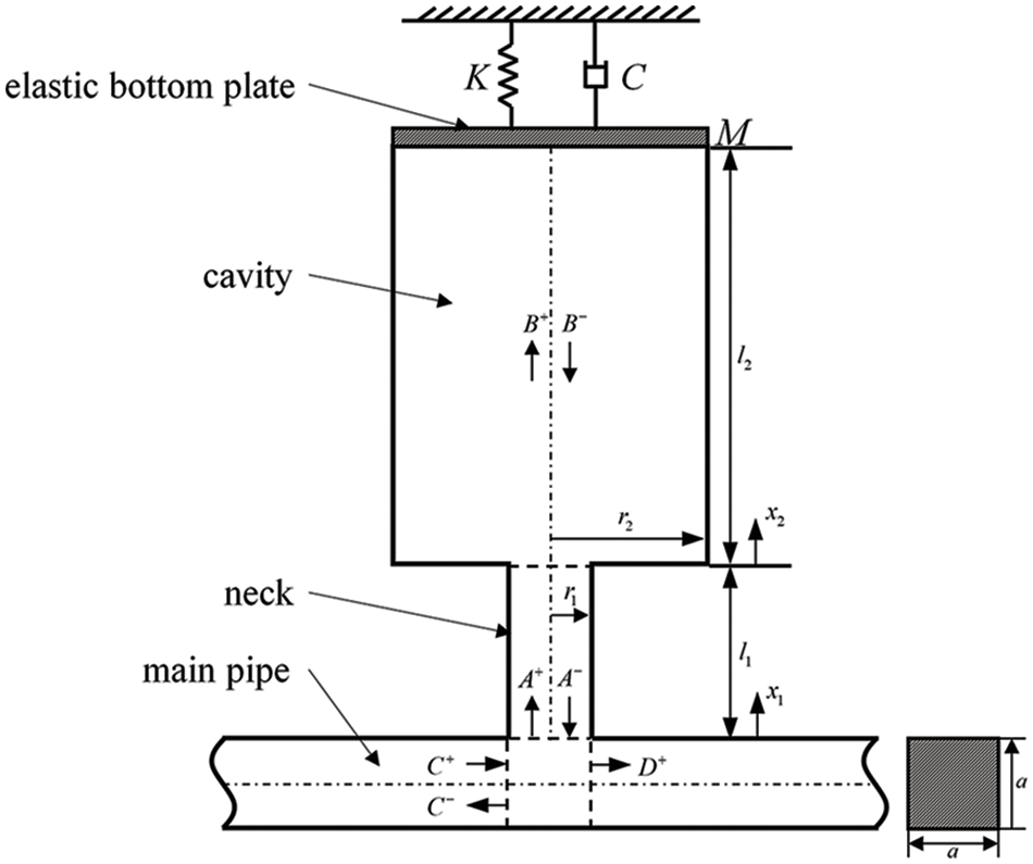
Figure 1: Schematic diagram of simplified model of Helmholtz resonator with elastic bottom plate
As shown in Fig. 1, at the entrance of the neck (i.e.,
where
where
Similarly, at the entrance of the neck (i.e.,
Then, the particle velocity
Since the sound pressure is continuous and the mass flux of particles is conserved, there is an equality relationship at
where
Similarly, the following relationship exists at the elastic bottom plate (i.e.,
where
Here,
At the interface between the main pipe and the resonator, the following equation also exists
where
According to the Eq. (5), at the entrance of the neck (i.e.,
Further, we can obtain STL as follows:
It should be mentioned that in this paper, we corrected the neck length from
3 Parameters Setting and Model Validation
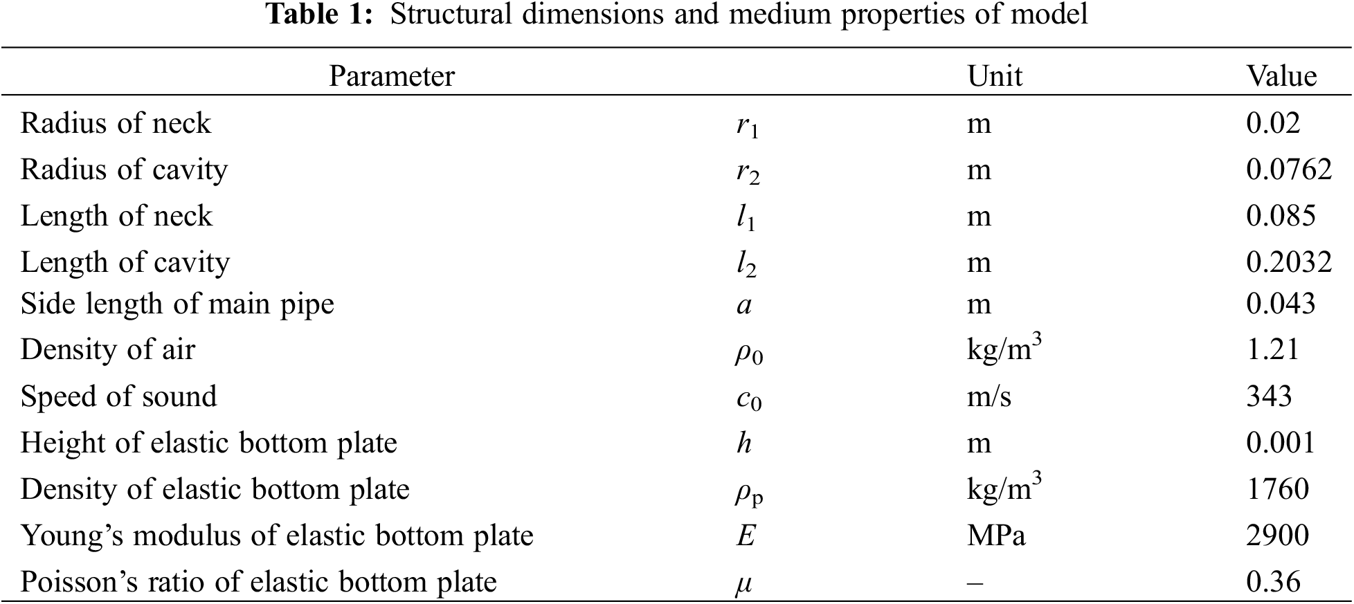
Table 1 lists the structural dimensions and medium properties of the model shown in Fig. 1, which are consistent with the data in the study of the Selamet et al. [10]. To better investigate the coupling between the elastic plate vibration and the sound pressure inside the cavity of Helmholtz resonator, the structural natural frequency f of the elastic bottom plate remains the same as the resonant frequency f0 of the Helmholtz resonator. The material of the elastic bottom plate is Polyvinyl Chloride (PVC) whose parameters are also listed in Table 1. In the one-dimensional analytical calculation, when considering the resonator bottom plate elasticity, the equivalent mass M and stiffness K parameters of the SDOF vibration system on the elastic bottom plate are obtained as 0.06036 kg and 26,623.8 N/m, respectively, according to the kinetic energy equivalence principle. The equivalent damping C of the bottom plate is set to 1.6036 Ns/m (i.e., the damping ratio is 0.02). When the bottom plate of the resonator degrades to rigid,
The three-dimensional finite element model (FEM) of Helmholtz resonator with elastic bottom plate is established corresponding to the parameters in Table 1, as shown in Fig. 2. All the walls are set to be rigid when the elasticity of the bottom plate is not considered, and the rest of the walls of the resonator other than the bottom plate are set to be rigid when considered. The damping ratio of elastic bottom plate is also set to 0.02. The air domain is discretized using tetrahedral elements, while the structural domain is discretized using shell elements and triangular mesh. Table 2 shows the mesh irrelevance test and the resonant frequencies of the Helmholtz resonator for different grid size. When the maximum grid size in the computational domain is less than 0.03 m, the change of the resonant frequencies is less than 1%, which meets the requirements for mesh irrelevance. In order to balance calculation accuracy and efficiency, the maximum mesh size is set to 0.02 m.
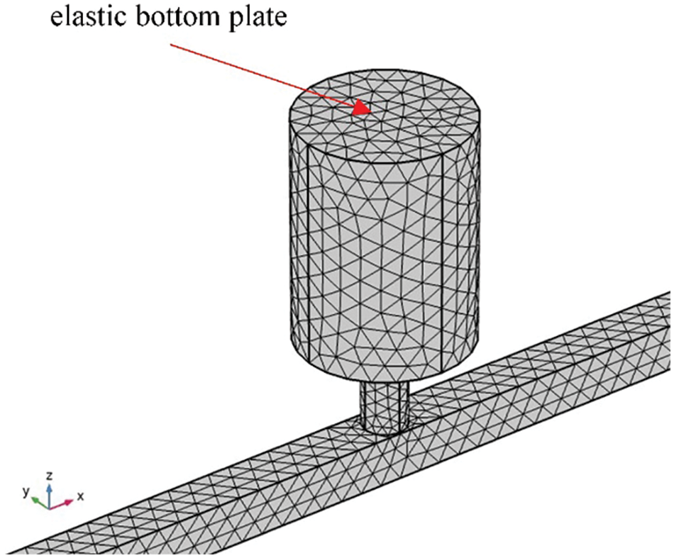
Figure 2: Three-dimensional FEM of Helmholtz resonator with elastic bottom plate
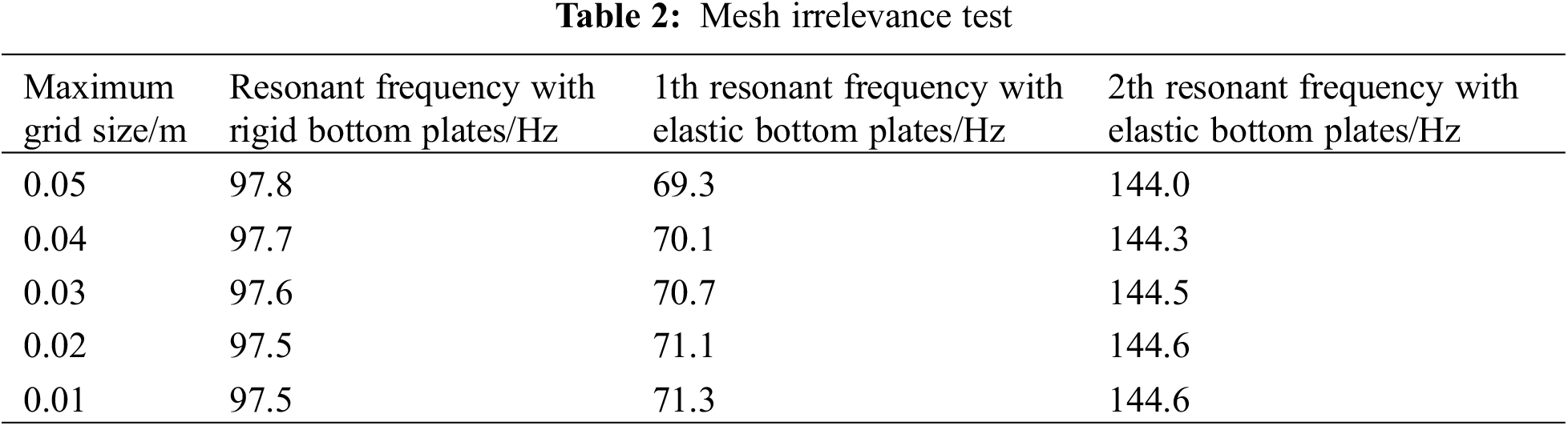
Fig. 3a compares the STL curves of the resonator with rigid bottom plate obtained using Eq. (15), from the study of the Selamet et al. [10], and three-dimensional FEM. It shows that the STL curves obtained by the three methods are almost consistent, and the difference of the resonant frequencies between three methods is less than 1.5 Hz, indicating that the simplified theoretical model with rigid bottom plate in this paper is correct. Fig. 3b compares the STL curves of the resonator with elastic bottom plate obtained using Eq. (15) and three-dimensional FEM. It shows that the results obtained by the two methods are almost consistent, indicating that the established one-dimensional lumped-parameter analytical model considering structure-acoustic coupling in this paper is also correct.
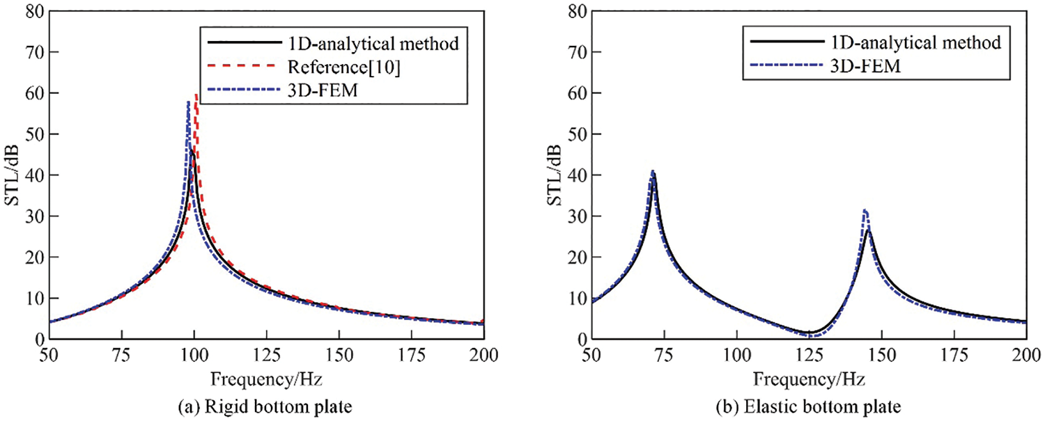
Figure 3: Comparison of sound transmission loss of resonators with rigid and elastic bottom plates. (a) Rigid bottom plate [10] (b) Elastic bottom plate
4 Effect Analysis of Parameters
It can be seen from comparing the STL curves in Fig. 3a,b that the elasticity of the bottom plate makes the STL peak of resonator split into two peaks, due to the strong coupling between the structural vibration of the elastic bottom plate and the acoustic pressure inside the resonator cavity. The influence of the dynamic parameters (stiffness, mass, damping) of the elastic bottom plate on the STL of the Helmholtz resonator is analyzed using one-dimensional lumped-parameter analytical model and discussed in the following sections.
4.1 Change of Equivalent Stiffness
When only changing the stiffness of the SDOF vibration system as shown in Table 3 to increase the natural frequency of the bottom plate, the vibration velocity response of the elastic bottom plate and the STL of the resonator are calculated and shown in Fig. 4. The results in Fig. 4a show that the peak frequency of the vibration velocity response increases with increasing the stiffness, while the amplitude gradually decreases. It can be seen from Table 3 that the difference of the resonant frequencies of the elastic bottom plate with and without considering the coupling gradually decreases with increasing the stiffness, indicating that the coupling between the elastic bottom plate vibration and the acoustic pressure inside the resonator cavity gradually weakens. As shown in Fig. 4b, the first peak frequency and amplitude of the STL increase with increasing the stiffness; the second peak frequency increases with increasing the stiffness, while the peak amplitude decreases; when the natural frequency of the bottom plate reaches three times the acoustic resonant frequency of the resonator, the first peak frequency and amplitude of the STL are close to those of the rigid bottom plate case, and the second peak almost disappears, which means that the vibration of the elastic bottom plate and the acoustic pressure inside the resonator cavity are decoupled.
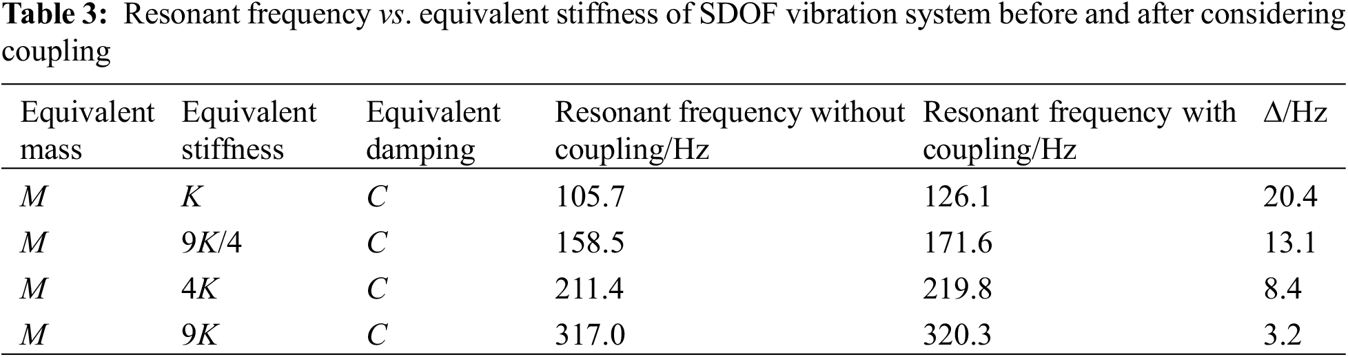
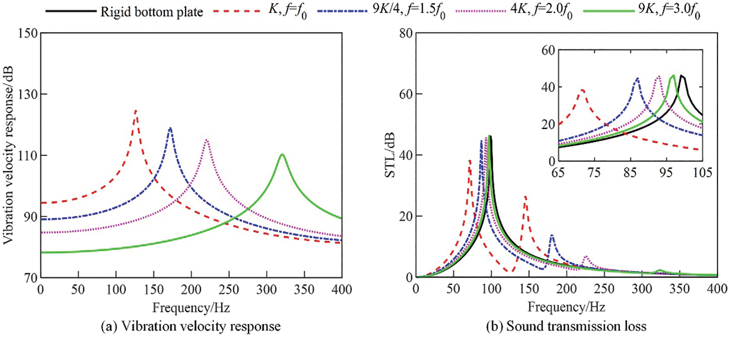
Figure 4: Vibration velocity response of elastic bottom plate and STL of resonator for different equivalent stiffness (Reference value of vibration velocity is 1 × 10⁻⁹ m/s, the same below and omitted). (a) Vibration velocity response, (b) Sound transmission loss
When only changing the mass of the SDOF vibration system as shown in Table 4 to increase the natural frequency of the bottom plate, the vibration velocity response of the elastic bottom plate and the STL of the resonator are calculated and shown in Fig. 5. The results in Fig. 5a show that the peak frequency of the vibration velocity response increases with decreasing the mass, while the amplitude gradually increases. It can be seen from Table 4 that the difference of the resonant frequencies of the elastic bottom plate with and without considering the coupling gradually decreases with increasing the mass, indicating that the coupling between the elastic bottom plate vibration and the acoustic pressure inside the resonator cavity gradually weakens. As shown in Fig. 5b, the first peak frequency and amplitude of the STL increase with decreasing the mass; the second peak frequency increases with decreasing the mass, while the peak amplitude decreases; when the natural frequency of the bottom plate reaches two times the acoustic resonant frequency of the resonator, the first peak frequency of the STL basically tends to constant value, and is less than the frequency corresponding to rigid bottom plate; when the natural frequency of the bottom plate reaches three times the acoustic resonant frequency of the resonator, the second peak of STL still exist, which indicated that the vibration of the elastic bottom plate and the acoustic pressure inside the resonator cavity are still coupled. On the other word, the decoupling between the vibration of the elastic bottom plate and the acoustic pressure inside the resonator cavity is more difficult to achieve by changing mass alone than by changing stiffness alone.
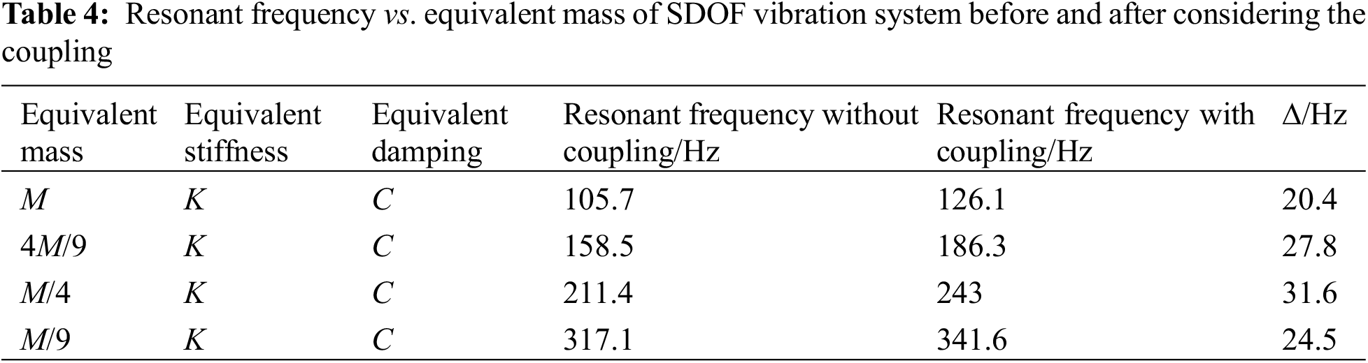
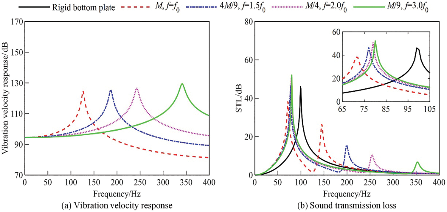
Figure 5: Vibration velocity response of elastic bottom plate and STL of resonator for different equivalent masses. (a) Vibration velocity response, (b) Sound transmission loss
For the homogeneous plate, the plate mass is proportional to the thickness and bending stiffness is proportional to the third power of the thickness. As shown in Table 5, the natural frequency of the resonator elastic bottom plate is adjusted by changing the plate thickness, i.e., simultaneously change equivalent mass and stiffness of the SDOF system. The vibration velocity response of the elastic bottom plate and the STL of the resonator for different thickness of elastic bottom plate are calculated and shown in Fig. 6. The results in Fig. 6a show that the peak frequency of the vibration velocity response increases with increasing the thickness, while the amplitude gradually decreases. It can be seen from Table 5 that the difference of the natural frequencies of the elastic bottom plate with and without considering the coupling gradually decreases with increasing the thickness, indicating that the coupling between the elastic bottom plate vibration and the acoustic pressure inside the resonator cavity gradually weakens. As shown in Fig. 6b, the first peak frequency of the STL increase with increasing the thickness; the second peak frequency increases with increasing the thickness, while the peak amplitude decreases; when the natural frequency of the bottom plate reaches three times the acoustic resonant frequency of the resonator, the first peak frequency and amplitude of the STL are close to those of the rigid bottom plate case, and the second peak almost disappears, which means that the vibration of the elastic bottom plate and the acoustic pressure inside the resonator cavity are decoupled.
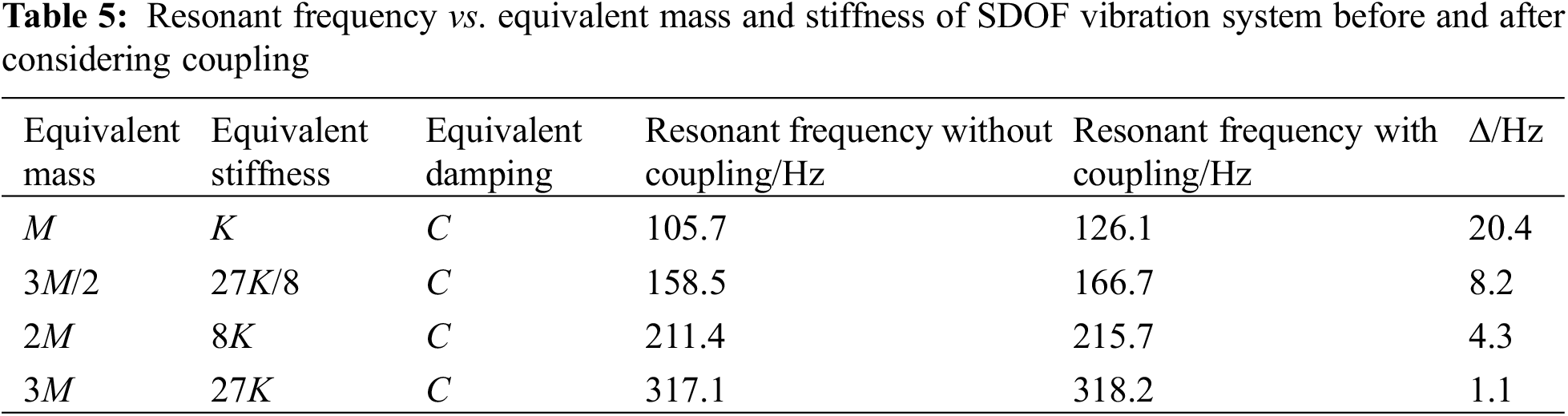
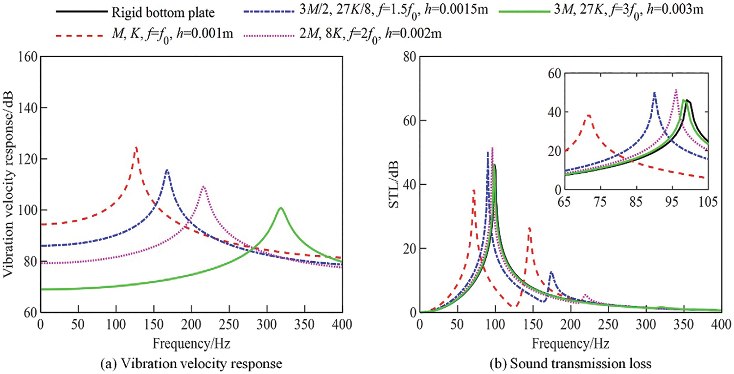
Figure 6: Vibration velocity response of elastic bottom plate and STL of resonator for different combinations of equivalent mass and stiffness (corresponding to different thickness of rigid bottom plate). (a) Vibration velocity response, (b) Sound transmission loss
The STLs obtained by finite element method for different bottom plate thicknesses (by adjusting the real constants of the shell element thickness of finite element model) are shown in Fig. 7a,b shows the frequencies corresponding to the first peak of the STLs of resonators with different ratio between the structural natural frequency
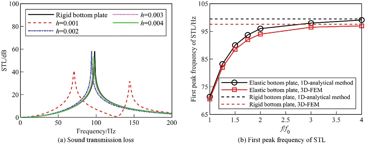
Figure 7: Effect of natural frequency of elastic bottom plate on sound transmission loss and its first peak frequency. (a) Sound transmission loss, (b) First peak frequency of STL
4.4 Change of Equivalent Damping
Fig. 8a,b show the STL of the resonator and the vibrational velocity response of the elastic bottom surface obtained by changing only the damping of the SDOF system, respectively. At this time, the natural frequency of the elastic bottom plate remains the same as the resonant frequency of the Helmholtz resonator. As can be seen from Fig. 8a, the vibration velocity response of the elastic bottom plate in the analyzed frequency band decreases significantly with increasing damping. As can be seen in Fig. 8b, the peak frequency of the STL decreases slightly with increasing damping, but the amplitude at the peak frequency decreases significantly, indicating that the sound attenuation capability of the resonator decreases with increasing damping of the cavity bottom plate.
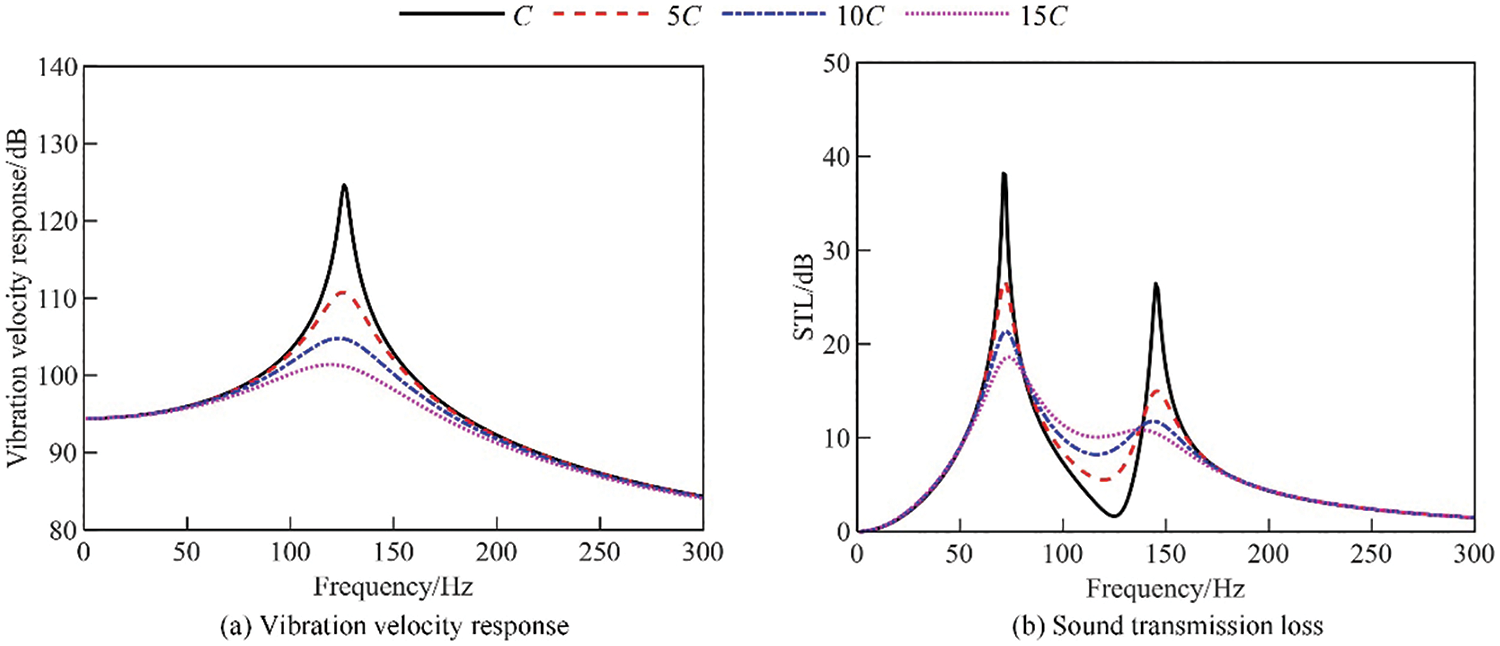
Figure 8: Vibration velocity response of elastic bottom plate and STL of resonator for different damping. (a) Vibration velocity response, (b) Sound transmission loss
In this paper, a one-dimensional lumped-parameter analytical model is derived to analyze the STL of a Helmholtz resonator with an elastic bottom plate, which takes into account the structure-acoustic coupling between the structural vibrations of the resonator wall and the sound pressure inside the resonator cavity. The effect of the dynamic parameters of the elastic bottom plate on the STL is then investigated. The following conclusions were obtained. (1) If the structural natural frequency of the elastic wall is close to the resonant frequency of the resonator (i.e., there exists strong coupling), the wall elasticity has a significant effect on the STL of a Helmholtz resonator, and the STL peak of the resonator will be split into two peaks. (2) The vibration of the elastic wall and the acoustic pressure in the Helmholtz resonator cavity can be effectively decoupled by increasing the stiffness and thickness of elastic wall. (3) When the natural frequency of the elastic wall reaches three times the acoustic resonant frequency of the resonator, the effect of the wall elasticity on the STL can be ignored. These conclusions provide guidance for the rapid and effective design of Helmholtz resonators.
Acknowledgement: The authors would like to acknowledge the support from the Open Foundation of the State Key Laboratory of Vehicle NVH and Safety Technology and the facilities provided by Chongqing Changan Automobile Co., Ltd. for the experimental research.
Funding Statement: This research was funded by the Open Foundation of the State Key Laboratory of Vehicle NVH and Safety Technology (Grant No. NVHSKL-202202).
Author Contributions: Writing—original draft: Liang Yang, Jie Zhang; Supervision, funding acquisition: Zhigang Chu; Methodology: Liang Yang, Jie Zhang, Jinfeng Xia; Simulation: Jie Zhang, Siwen Zhang; Validation: Jinfeng Xia, Siwen Zhang; Writing—review and editing: Siwen Zhang, Yang Yang, Zhigang Chu. All authors reviewed the results and approved the final version of the manuscript.
Availability of Data and Materials: The data used to support the findings of this study are available from the corresponding author upon request.
Ethics Approval: Not applicable.
Conflicts of Interest: The authors declare that they have no conflicts of interest to report regarding the present study.
References
1. Hu GB, Tang LH, Cui XB. On the modelling of membrane-coupled Helmholtz resonator and its application in acoustic metamaterial system. Mech Syst Signal Process. 2019;132(2):595–608. doi:10.1016/j.ymssp.2019.07.017. [Google Scholar] [CrossRef]
2. Zhu JZ, Qu YG, Gao H, Meng G. Nonlinear sound absorption of Helmholtz resonators with serrated necks under high-amplitude sound wave excitation. J Sound Vib. 2022;537(5):117197. doi:10.1016/j.jsv.2022.117197. [Google Scholar] [CrossRef]
3. Oblak M, Pirnat M, Boltezar M. Modal-interaction approach to the strong structural-acoustic coupling of an elastic Helmholtz resonator and an acoustic cavity containing a heavy fluid. J Sound Vib. 2022;535:117120. doi:10.1016/j.jsv.2022.117120. [Google Scholar] [CrossRef]
4. Panton RL, Miller JM. Resonant frequencies of cylindrical Helmholtz resonators. J Acoust Soc Am. 1975;57(6):1533–5. doi:10.1121/1.380596. [Google Scholar] [CrossRef]
5. Selamet A, Radavich PM, Dickey NS, Novak JM. Circular concentric Helmholtz resonators. J Acoust Soc Am. 1997;101(1):41–51. doi:10.1121/1.417986. [Google Scholar] [CrossRef]
6. Chanaud RC. Effects of geometry on the resonance frequency of Helmholtz resonators. J Sound Vib. 1994;178(3):337–48. doi:10.1006/jsvi.1994.1490. [Google Scholar] [CrossRef]
7. Dickey NS, Selamet A. Helmholtz resonators: one-dimensional limit for small cavity length-to-diameter ratios. J Sound Vib. 1996;195(3):512–7. doi:10.1006/jsvi.1996.0440. [Google Scholar] [CrossRef]
8. Ruan DF, Deng ZX. Effect correction of the cavity geometry of a resonant silencer on the resonance frequency. J Chongqing Univers. 2005;28(10):13–6 (In Chinese). [Google Scholar]
9. Ruan DF, Deng ZX, Yang C. Analysis of acoustic performance of the resonant silencer. Chin Intern Combust Engine Eng. 2006;27(1):66–70 (In Chinese). [Google Scholar]
10. Selamet A, Lee I. Helmholtz resonator with extended neck. J Acoust Soc Am. 2003;113(4):1975–85. doi:10.1121/1.1558379. [Google Scholar] [PubMed] [CrossRef]
11. Tang SK. On Helmholtz resonators with tapered necks. J Sound Vib. 2005;279(3–5):1085–96. doi:10.1016/j.jsv.2003.11.032. [Google Scholar] [CrossRef]
12. Liu HT, Zheng SF, Lian XM, Dan JB. The acoustic performance prediction of the Helmholtz resonator with a conical neck. ACTA Acust. 2014;39(3):353–9 (In Chinese). [Google Scholar]
13. Shi XF, Mak CM. Helmholtz resonator with a spiral neck. Appl Acoust. 2015;99:68–71. doi:10.1016/j.apacoust.2015.05.012. [Google Scholar] [CrossRef]
14. Cai CZ, Mak CM, Shi XF. An extended neck versus a spiral neck of the Helmholtz resonator. Appl Acoust. 2017;115(6):74–80. doi:10.1016/j.apacoust.2016.08.020. [Google Scholar] [CrossRef]
15. Mercier JF, Marigo JJ, Maurel A. Influence of the neck shape for Helmholtz resonators. J Acoust Soc Am. 2017;142(6):3703–14. doi:10.1121/1.5017735. [Google Scholar] [PubMed] [CrossRef]
16. Langfeldt F, Hoppen H, Gleine W. Resonance frequencies and sound absorption of Helmholtz resonators with multiple necks. Appl Acoust. 2019;2019(145):314–9. doi:10.1016/j.apacoust.2018.10.021. [Google Scholar] [CrossRef]
17. Griffin S, Lane SA, Huybrechts S. Coupled Helmholtz resonators for acoustic attenuation. J Vib Acoust-Trans ASME. 2001;123(1):11–7. doi:10.1115/1.1320812. [Google Scholar] [CrossRef]
18. Bi R, Liu ZS, Wang H, Wu H, Liu HJ. Analysis of acoustical performance of multi-chamber Helmholtz resonators. Trans Chin Soc Agric. 2008;39(10):48–51. [Google Scholar]
19. Xu MB, Selamet A, Kim H. Dual Helmholtz resonator. Appl Acoust. 2010;71(9):822–9. doi:10.1016/j.apacoust.2010.04.007. [Google Scholar] [CrossRef]
20. Cai CZ, Mak CM. Acoustic performance of different Helmholtz resonator array configurations. Appl Acoust. 2018;130(3):204–9. doi:10.1016/j.apacoust.2017.09.026. [Google Scholar] [CrossRef]
21. Dai HQ, Xia BZ, Yu DJ. Microparticles separation using acoustic topological insulators. Appl Phys Lett. 2021;119(11):111601. doi:10.1063/5.0059873. [Google Scholar] [CrossRef]
22. Dai HQ, Liu LB, Xia BZ, Yu DJ. Experimental realization of topological on-chip acoustic tweezers. Phys Rev Appl. 2021;15(6):064032. doi:10.1103/PhysRevApplied.15.064032. [Google Scholar] [CrossRef]
23. Dai HQ, Xue P, Lu EH, Wang L, Zhou LS. Experimental realization of a soft topological acoustic switch. Phys Rev B. 2023;107(14):144105. doi:10.1103/PhysRevB.107.144105. [Google Scholar] [CrossRef]
24. Zhang SW, Wu JH, Hu ZP. Low-frequency locally resonant band-gaps in phononic crystal plates with periodic spiral resonators. J Appl Phys. 2013;113(16):163511. doi:10.1063/1.4803075. [Google Scholar] [CrossRef]
25. Sun W, Chu ZG, Lang YF. Nonlinear sound absorption of coiling-up space under high amplitude acoustic excitation. Appl Acoust. 2024;220(11):109956. doi:10.1016/j.apacoust.2024.109956. [Google Scholar] [CrossRef]
26. Sun W, Li L, Chu ZG. Dual-frequency anti-nonlinear sound-absorbing metasurface via multilayer nested microslit resonators. Phys Scr. 2023;98(4):045702. doi:10.1088/1402-4896/acbf8a. [Google Scholar] [CrossRef]
27. Selamet A, Xu MB, Lee IJ, Huff NT. Helmholtz resonator lined with absorbing material. J Acoust Soc Am. 2005;117(2):725–33. doi:10.1121/1.1841571. [Google Scholar] [PubMed] [CrossRef]
28. Yang D, Wang X, Zhu M. The impact of the neck material on the sound absorption performance of Helmholtz resonators. J Sound Vib. 2014;333(25):6843–57. doi:10.1016/j.jsv.2014.07.034. [Google Scholar] [CrossRef]
29. Khairuddin MH, Said MFM, Dahlan AA, Kadir KA. Review on resonator and muffler configuration acoustics. Arch Acoust. 2018;43(3):369–84. [Google Scholar]
30. Photiadis DM. The effect of wall elasticity on the properties of a Helmholtz resonator. J Acoust Soc Am. 1991;90(2):1188–90. doi:10.1121/1.402026. [Google Scholar] [CrossRef]
31. Norris AN, Wickham G. Elastic Helmholtz resonators. J Acoust Soc Am. 1993;93(2):617–30. doi:10.1121/1.405481. [Google Scholar] [CrossRef]
32. Zhou CG, Liu BL, Li XD, Tian J. Effect of elastic cavity walls on acoustic characteristics of a water-filled Helmholtz resonator: equivalent lumped parameter model for cylindrical cavity. Acta Acust. 2007;32(5):426–34. [Google Scholar]
33. Nudehi SS, Duncan GS, Farooq U. Modeling and experimental investigation of a Helmholtz resonator with a flexible plate. J Vib Acoust. 2013;135(4):041102. doi:10.1115/1.4023810. [Google Scholar] [CrossRef]
34. Kurdi MH, Duncan GS, Nudehi SS. Optimal design of a Helmholtz resonator with a flexible end plate. J Vib Acoust. 2014;136(3):031004. doi:10.1115/1.4026849. [Google Scholar] [CrossRef]
35. Singiresu R. Mechanical vibrations. New York: Addison-Wesley Publishing Company; 1990. [Google Scholar]
Cite This Article
 Copyright © 2024 The Author(s). Published by Tech Science Press.
This work is licensed under a Creative Commons Attribution 4.0 International License , which permits unrestricted use, distribution, and reproduction in any medium, provided the original work is properly cited.
 Downloads
 Citation Tools