 Open Access
ARTICLE
Tactile Response Characterization of a Dynamic System Using Craig-Bampton Method
Department of Mechanical Engineering, Mepco Schlenk Engineering College, Sivakasi, Tamilnadu, 626005, India
* Corresponding Author: S. Pradeepkumar. Email:
Sound & Vibration 2022, 56(3), 221-233. https://doi.org/10.32604/sv.2022.014889
Received 06 November 2020; Accepted 16 December 2021; Issue published 10 August 2022
Abstract
Vibrational characteristics in small horizontal axis wind turbine system are presented in this study with a system concept called tactile response and substructuring. The main focus is on managing the dynamic properties like vibration, noise, and harshness that occur during the operational mode. Tactile response is defined as the response of subsystem which is induced when a human body touches a vibrating system. Sub structuring is a computational method used to reduce the dynamic behavior of a large complex system with a smaller number of degrees of freedom without disturbing the mesh size of the model. Sub structuring has the ability to combine numerical results along with the experimental results. Combination of substructuring and tactile response is applied in this study. Mode shapes of the system are analyzed and results obtained are correlated within this study to provide better optimization of the results. Wind turbine excited with wind energy depends on wind speed. Torsional vibration has a significant role in determining dynamic properties. Torsional vibration is caused as a result of the rotation of the turbine blade and depends on wind speed. The study gives importance to investigating the ability to simulate the numerical method and tactile response to predict and improve dynamic properties.Keywords
Vibrational characteristics in wind turbine system are analyzed using computational method called the Craig-Bampton method. Craig-Bampton method is an effective method in dynamic substructuring method and is widely used in the dynamic analysis of large complex systems. In this method, we can reduce a large number of degrees of freedom of a finite element model to a model with a smaller number of degrees of freedom. Noise, Vibration, and Harshness (NVH), and structural health monitoring of the dynamic system can be analyzed with less computational cost. The concept of tactile response is introduced in this paper. The finite element modelling method is adopted to model the components and the results are correlated with experimental data. Each component is analyzed separately. Generally, three operating conditions employed in wind turbine. They are transient events like a start-up or emergency stop, rated power production at the extreme working condition and finally parked condition. The torsional vibrations with low frequency lead to changes in the operational mode. To improve design parameters as well as dynamic parameters in terms of accuracy we need to optimize design concepts.
Arteaga-López et al. [1], in their investigation about to improve, the wind resource assessment by using computational fluid dynamics. Awadallah et al. [2] studied micro-crack and defects in a small wind turbine blade using kriging model. Baik et al. [3] presented the vibrational characteristics of a seat system in an automobile using finite element method, there for the noise, vibration harshness (NVH) performance is managed using tactile, visual and acoustic view. Chen et al. [4] studied the coupled longitudinal and transverse vibrations of a submarine elastic propeller-shaft-hull system using the Frequency response function-based substructuring method. Chen et al. [5] proposed a new method to analyze vibrational fault in wind turbine using variational decomposition and energy methods. Choi et al. [6] proposed continuum design sensitivity method for estimating dynamic frequency response of structural acoustic system. Craig et al. [7] introduced the concept of treating complex structures as an assembly of substructure, in this context mass and stiffness matrix of substructure establish geometrical compatibility condition along with substructure boundaries and provides two types generalized coordinates. Craig et al. [8] provided an extensive introduction to numerical methods for computing natural frequencies and mode shapes for computing transient response. A systematic introduction to finite element methods in structural dynamic analysis and the practical aspect of component mode synthesis in dynamic analysis. Concept of mathematical modeling and experimental validation of mathematical models. Fagiani et al. [9] focused on the tactile perception, because a clear understanding of the tactile sense is essential for many applications. Géradin et al. [10] explained the theory of mechanical vibrations and computational methods with respect to structural dynamics. Hage et al. [11] established the effect of increased torsional vibrations on vehicle NVH performance and ways to improve vehicle performance. The design parameters affecting vehicle NVH performance and to develop an optimized relation between torsional vibration and mountings. Hansen [12] provided an insight into wind turbine aerodynamics and aero elasticity. Hu [13] Proposed vibration mitigation method to analyze complex mechanical systems. Flodén et al. [14] The elastomeric vibration isolators are modelled using dynamic substructuring method to obtain accurate and efficient model reduction. Elastomeric isolators are used as coupling element between two substructures. New mathematical model is introduced to investigate horizontal axis wind turbine blade vibration in flap-wise direction [15]. Kinetic and potential energy of wind turbine blade are analyzed by considering gravitational force, centrifugal force and inertial force of turbine blade. Klerk et al. [16] presented a general framework which allows classification of dynamic substructuring methods and highlights the interrelation and difference between various publications related with substructuring method. Kullaa [17] concept of analytical virtual sensing technique in structural dynamic was proposed by modelling only part of the structure and applying Craig-Bampton substructuring method. Investigated the various types of errors caused due to substructuring, modal truncation, noise and inaccurate physical parameters. Kumar et al. [18] established the fatigue behavior of wind turbine blade with response to different frequencies. Pre-stressed modal analysis and harmonic analysis of the turbine blade for different composite materials are analyzed. Liu et al. [19] investigated the effect of blade vibrations on life time aerodynamic fatigue loads and vibration induced velocity in aerodynamic load analysis. Mabrouk et al. [20] characterized the global dynamic behavior of the Darrieus turbine by investigating the effect of the rotational speed. Mohammadi et al. [21] proposed a new selective electromagnetic actuation technique to control the vibrations of multiple tactile elements using a single coil based on their individual mechanical resonance frequencies. O’Brien et al. [22] reviewed horizontal axis turbine aerodynamics by investigating the blade deflection under aerodynamic loads. Petyt [23], an introduction to vibration analysis using finite element methods and mathematical modelling of dynamic systems. Voormeeren et al. [24] proposed a general approach to mixed boundary component mode synthesis by considering component reduction and component assembly separately. Pradeepkumar et al. [25], in their investigation, the dynamic charecteristics of small horizontal axis wind turbine is established using dynamic substructuring technique and also proposed the concept of tactile response of dynamic system. Wood [26] provided a thorough grounding in analysis, designing, and installation procedure of a small wind turbine. Wu et al. [27] have studied two order reduction methods called transient proper orthogonal decomposition (T-POD) method and polynomial dimensional decomposition (PDD) methods to reduce the dimensional complexity in deterministic and stochastic system.
Review of literature shows that a number of studies have been conducted to study the structural and vibrational characteristics in a wind turbine irrespective of its size. Structural dynamic characterization is to provide the mechanical efficiency of the mechanical equipment’s of wind turbine operating within the vibrational limits. In this context, the main focus of these studies on renewable energy system to provide clean and green energy concept to the world. In the current scenario, i.e., in the context of the global warming and pollution caused due the burning of fossil fuels, wind energy has a vital role. Nowadays, small wind turbines are extensively used for commercial purpose, household application and marine application like sundry hulls, yachts etc as an alternate source of energy. The rated power performance of wind turbine is connected with structural response during its operation. Natural frequency and transient modes are collected during its operation is utilized in structural dynamic characterization.
The study is to explore the effectiveness of the Craig-Bampton method in determining tactile response in the structural dynamics of a complex system. Tactile response concept is extensively used in automobiles in conjunction with steering vibration and its effects. Here we are reporting a comprehensive study to establish the understanding of tactile response in small horizontal axis wind turbine.
Craig-Bampton method is used to solve very large and complex structural problems in structural dynamics. Craig-Bampton method works on the principle of substructuring concept. In the Craig-Bampton method, the complex structure is divided into a number of substructures or components to reduce its complexity in large-dimensional systems and to avoid its redundancy. These reduced substructures or components are called reduced-order models of the entire system. The reduced-order models are used to assemble a reduced-order–order model of the whole structure. Substructure technique is applied to get component modes which are acting as basis vector for the components. Craig-Bampton method is the most popular technique in the substructuring family. It is employed for reducing the size of Finite element models when two or more sub-components are interconnected. It combines the motion of boundary points of sub-components with mode under the assumption that boundary points are in a fixed condition. Fixed interface mode provides the shape of all dynamic systems and the component modes are not the natural frequencies of the structure. The full model validation of the structure is not possible by using the measurement of the whole structure. In the Craig-Bampton method, the motion of interface fixed mode is equal to the number of interface degrees of freedom of the sub-components.
The concept of substructuring in structural dynamics is explained in a rigorous manner by [7,10,17]. The governing equation of motion for a dynamic system is represented as
where M is the mass matrix of component,
where Ψ is the component mode matrix which consists of selected component modes as columns and q(t) is the component generalized coordinate. Partitioned equation of motion for the system (1) can be written as
The subscript ‛i’ denotes the interior degree of freedom and ‛b’ denotes interface degree of freedom. Internal forces are neglected because degrees of freedom with external loads are assigned to the interface degrees of freedom and Eq. (2) changes to
Craig-Bampton method utilizes two sets of component modes and they are called normal modes and constraint modes. The fixed interface mode gives mode shape of the dynamic system and all the interface degrees of freedom are fixed and we have
Component fixed interface normal modes are obtained by retaining all boundary degrees of freedom and solving the generalized Eigenvalue problems of the system results in
The number of lowest modes is defined as
The second set of component modes in the interface constraint modes is having static displacement when the interface degrees of freedom are known. The inertial forces are neglected and the Eq. (4) changes to
The Craig-Bampton method consists of two interface degrees of freedom. The first interface degrees of freedom is provided by unit displacement and the second one is fixed condition, i.e.,
The interface constraint modes of the sub component change to
In this study, we are considering only Ritz vectors, so the interior force in Eq. (3) is considered to be zero and the Ritz vectors replace the mode shapes. The linear combination of the mode shapes gives the approximation of excitation. Craig-Bampton method were proposed by Craig and Bampton. The Craig-Bampton method (CB) is quickly accepted by the dynamic communities due to its computational ability towards substructure analysis on complex dynamic systems. So, it became an important research topic in the field of structural dynamics and in vibrational analysis. Craig-Bampton method allows the direct coupling of substructure components of the reduced model and the physical interface degrees of freedom of internal boundary are retained in the reduced dynamic model. This reduced model facilitates easy assembly of the reduced substructures as super elements in common FE codes. A number of engineering considerations to be followed to obtain interface modes and a limited number of modes with lowest frequency are selected for the study.
Vibrational characteristics of a small horizontal axis wind turbine (SHAWT) are expressed in terms of computational methods. Nowadays, computational methods are very extensively used for various engineering analysis because the development of high software and hardware and this gives accurate results. Noise, Vibration, and Harshness (NVH) analysis, a new approach is introduced in this study which comprises of a model reduction method called Craig-Bampton method and tactile response of the vibrating system. Tactile response is a phenomenon which normally comes in the field of automobiles.Baik et al. [3,11] established tactile response phenomenon in the vibrating structure of an automobile structure through analytical research, to investigate the dynamic behavior of sub-systems in the automobile structure. The response of sub-systems which is induced, when the human body contacts the steering wheel, footrest, and seats. Tactile response method is applied in a small wind turbine because the small wind turbine is extensively used in commercial buildings, residential buildings and marine structures to generate electricity. Wind turbines are excited through wind power. The mode of excitation depends on wind velocity, the aerodynamics of the wind turbine blade. In order to maintain the structural health of the small wind turbine (SWT) it requires continuous monitoring. Flow-induced vibration and torsional vibrations are the main factors which affect the performance and structural integrity of the system. The resonance frequency of tactile elements results in active vibrations of the vibrating components, so we are approaching the concept of combining tactile response and Craig-Bampton method in this paper.
4 Structural Dynamics in System Design
Nowadays, the concept of clean energy and green energy is widely accepted to protect the environment. Power is generated from burning fossil fuels and nuclear reactors cause a huge impact on the environment. Emission from thermal power plants and nuclear waste from nuclear power plants are causing environmental problems like greenhouse effects, global warming etc. If we prefer renewable energy as a source of power generation, these problems can be reduced significantly. Wind energy is a form of renewable energy source. A wind turbine is a device used to extract power from wind energy. Due to the rapidly increasing growth clean and green energy concept, we selected wind turbine and its structural dynamics. In this paper, the concept of tactile response characterization is applied in a small horizontal axis wind turbine with 500 Watts power output, 300 rpm and has a rotor diameter of 1820 mm. Hybrid wind turbine tower is used in this study. The test structure consists of three blades made of glass fibre reinforced polymer (GFRP) and it is a three-bladed structure. We choose a three-bladed structure because it has the ability to provide constant inertia that results in a reduction in structural vibration. The efficiency of the wind turbine depends on the rotational speed of the turbine (rad/sec) and power output (W). Fig. 1a shows the actual view of the wind turbine used in this study and Fig. 1b shows the dynamic model of the test structure represented by spring with stiffness (K), mass (M), and damper (C).
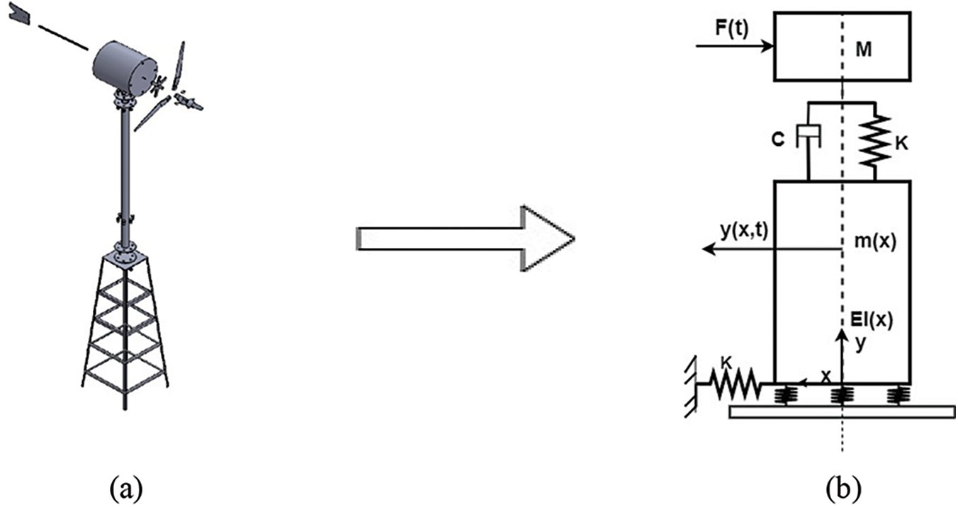
Figure 1: (a) Horizontal axis wind turbine, (b) Dynamic model
Selection of wind turbine mainly depends on wind speed. Normally, there are two types of wind conditions that are considered during the design of the wind turbine. They are Zero to Maximum wind speed condition and the Maximum wind speed condition. Normally, we select the maximum wind speed condition. The turbine blades are facing the direction of the wind to get maximum power output. Aerodynamic consideration has a vital role during the blade design. Structural dynamics due to rotor speed leads to harmonic vibrations. The efficiency of the turbine blade depends on the wind speed reaching the turbine blade and the velocity of the wind leaving the blade after excitation. The blade is designed aerodynamically to capture maximum power from the wind flow.
While designing the tower for the horizontal axis wind turbine it should be kept in mind that the system should be of the lowest natural frequency and it should be known whether the system is stiff or of soft condition to determine structural properties. In a stiff tower frequency to rotor speed ratio is substantially larger than the number of blades and in the case of the soft tower, the natural frequency ratio is substantially less than one. The tower natural vibration mode has a frequency higher than the repetitive force caused by blade moment. Structural problems in the hub and resonant vibrations in the tower are to be considered during the design process. In this study, a hybrid tower structure is used. The hybrid tower is a combination of lattice structure and tubular structure. The tower is designed to withstand stiffness over strength.
The natural frequency and mode shape of the vibrating system has a significant role in the structural health. The static and dynamic stresses are caused due to the gravitational force and centrifugal force acting on the wind turbine. The periodic loading acting on the wind turbine components depends upon the system response as a whole and in particular natural frequency and vibration modes. Natural modes of the wind turbine depend on the rotating elements like a blade and other connected components coupled together derive system modes. A wind turbine consists of a very large number of natural modes with respect to its own natural frequency. Dynamic signals obtained from accelerometer are analyzed carefully for their frequency which provides the vibration modes. Heavy wind load excitation leads to deflection in blade and tower rather than stress. Up-wind and down-wind velocities of the structure lead to the aerodynamic damping. The gravitational force causes bending.
Modelling and analysis of the complex real-world problem using the analytical method. Finite element method (FEM) can be used to set up the structural dynamic model in the form of the equation. A dynamic model of the structural system in the form of Eq. (1) and projecting the equation of motion. The structure is discretized into nodes and elements. Local approximation of the discretized models defined by deflections and velocities, which depends on the structural loads. Deflection shape in this method is described as a linear combination of basis functions, which corresponding to the eigen modes with the lowest eigen frequencies. Shape functions and discrete degrees of freedom are based on the boundary conditions of the finite element model. The structural and aerodynamic models of the systems are therefore coupled. The principle of virtual work is a method is used to set up the mass matrix, stiffness matrix, and damping matrix of the discretized mechanical system.
The turbine blade is the major component wind turbine assembly. The turbine blade is made of Glass fiber reinforced polymer (GFRP). The turbine blade manufactured by gravity molding. Fig. 2 is the FE model of the wind turbine blade used. The blade model consists of 11376 quadrilateral triangular shell elements and 35598 tetra solid volume elements. The average spacing between two nodes is approximately 5 mm. Craig-Bampton method is employed for model reduction.
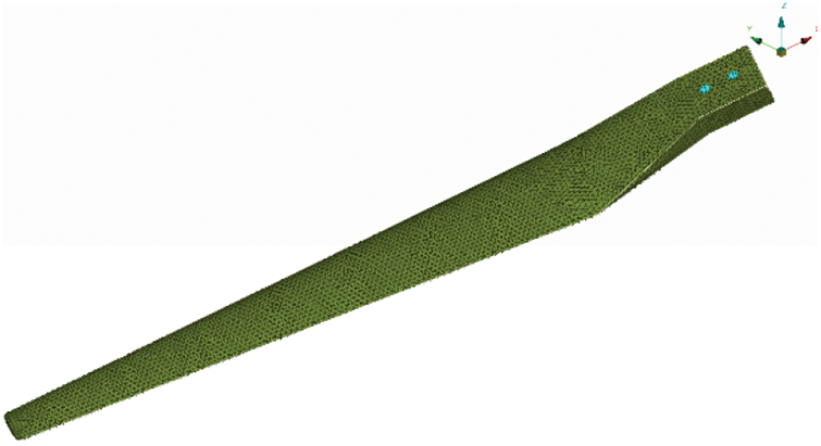
Figure 2: FE model of turbine blade
The wind turbine blade undergoes massive failure due to the aerodynamic loads acting in the turbine blade. The tip of the turbine blade is mostly affected by these aerodynamic forces and leads to deflection of the rotor blade. The bending twist phenomena of the turbine blades helps to reduce the loading effects. The turbine blade is tested for its reliability and strength under fixed condition. The deflection of the turbine blade estimated using Timoshenko beam theory. Depending on wind conditions, the blades turn at rates between 0 and 300 revolutions per minute. Considering the length of the wind turbine blades with average wind speeds blade velocity of wind turbine varies. The slender length of the blade has vital role in determining the wind turbine velocity. Fig. 3 exhibiting the wind turbine blade bending at various frequencies.
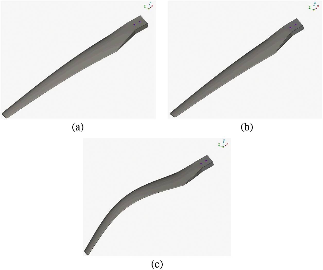
Figure 3: Blade bending. (a) 58.6 Hz, (b) 184 Hz, (c) 227 Hz
Structural integrity and the vibrational response of the wind turbine blade are determined by Sine sweep test. The test is performed using an electrodynamic shaker. An electrodynamic shaker is a testing machine which is used to provide source function to the test specimen. The generated frequency response function has the ability to show the fatigue life, resonant frequency, and random frequency functions. In the sine sweep test, the transverse between low and high frequencies can be determined. In sine sweep test the ‛g’ value is kept constant, and displacement can be constant or variable in nature. Sine sweep test is performed to identify the resonance by comparing the vibrational response of the test specimen with the shaker. Here the wind turbine blade is tested to a frequency of 30 and 50 Hz. The test specimen has a weight of 1.98 kg, 910 mm in length, density 1.55e−6 kg/mm3 and Young’s modulus 75000 Mpa. Poisson’s ratio of the material is 0.25. Two sensors are used in this test. Sensor with number 18862 and sensitivity 28.53 mV/g is attached to the shaker table. Sensor with number 18863 and sensitivity 29.59 mV/g is fixed into the strategic points of the test specimen. The electrodynamic shaker has the force up to a maximum level of 2500 kgf and frequency varies in the range of 5 to 2800 Hz. Acceleration 0.1 g is considered as 5 Hz, 0.2 g is considered as 20 Hz and 0.3 g is 30 Hz. The acceleration varies in the range of 0 to 100 g. The shaker has a velocity of 1.7 m/sec and displacement of 51 mm (P–P). The test is conducted in a frequency range of 0–50 Hz and time elapsed for the test is 30 and 50 s respectively. In sine sweep test only one excitation frequency at a given time. In this, each mode will be excited individually, if the modal frequencies are separated properly.
Fig. 4 shows the experimental set-up in which the wind turbine blade is clamped to the electrodynamic shaker with proper nuts and bolts with a ‘C’ channel fixture.

Figure 4: Sine sweep test set-up
Shaker test is performed to predict the failure mode of the component and to improve the reliability of the component by observing the dynamic behaviour of the component. Vibrational characteristics are obtained by introducing an external force in to the component, which result the shaker excitation. The excitation signals give the linear approximation to the frequency response function of the system. Fig. 5 represents the forward direction curve obtained when the specimen is tested with 30 Hz frequency 30 s by fixing sensor strategic points on the test specimen. Fig. 6 is the sine sweep curve for 50 Hz frequency. The plots showing sinusoidal vibrations with a frequency range up to a maximum of 50 Hz. Slopes and crossover points are calculated automatically. The linearity of stiffness and damping are estimated.
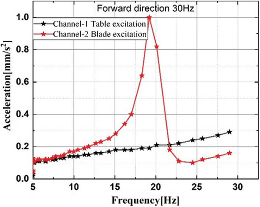
Figure 5: Sine sweep forward direction 30 Hz
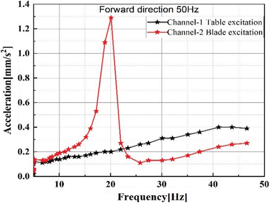
Figure 6: Sine sweep forward direction 50 Hz
5.3 Experimental Modal Analysis-Wind Excitation
Wind turbine size varies according to the power output and usage. Massive structure wind turbines are used for generating high output and small wind turbines are used in small commercial buildings, for household application, and for marine structures. The vibration caused due to its working will cause damage to the turbine structure as well as the buildings where it is installed. To avoid such difficulties and to rectify the problems vibrational analysis is mainly carried out in small machines. The vibration effect will lead to a reduction in power and enhancement in noise. In the modal analysis, the structure is considered to be ideal. Modal analysis has a significant role in NVH analysis. Frequency response function (FRF) is an important dynamic property in the vibrational analysis. Frequency response function depends on the excitation force acting in the wind turbine structure. The data are acquired during its working conditions through data acquisition system. These data provide the response level. Eigen frequencies of the wind turbine are caused due to the rotation of the blade under different rpm, centrifugal force, and Coriolis force acting on it. The blade properties are estimated by a sine sweep test and by the parked condition. The experimentally obtained data are analyzed thoroughly. Time histories provide the system dynamic response in connection with the specified loading condition and time dependence. Mode shapes are analyzed experimentally and numerically during its excitation. Rotor harmonics of the blade are obtained from the rpm of the machine. The rpm varies from 0–300. In this study, the aerodynamic damping is not considered. Natural frequencies during the operational mode indicate a chance of the occurrence of resonance condition. The rotations of the blade depend directly on the wind speed. The flap mode and fore-aft modes depend on the rotor dynamics and the rotational speed of the system. The study focuses on determining the crossover frequency of the system and the possibility of causing resonance condition.
Fig. 7 shows the schematic view of the test data input for the vibration analysis using vibrometer. In this modal analysis, the accelerometers are fixed at various locations of the wind turbine and placed in x, y, and z directions in the test location points. The accelerometers are fixed with a magnetic mount. The accelerometer used in this study has a sensitivity of 100 mV/g. In this study, a two-channel vibrometer is used. The two channels are A and B. Channels A and B provide the spectrum and the waveform of the test results in digital form. The spectrum data consist of the overall RMS level of frequency, velocity, acceleration, and the peak-to-peak displacement of the test data.
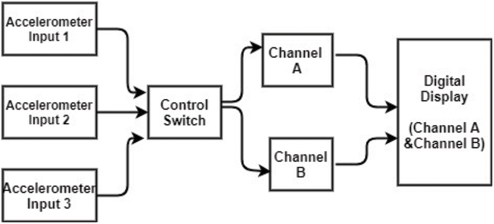
Figure 7: Schematic view: Modal analysis
The experimental results obtained are very useful for correcting the numerical model and also to perform comprehensive study. The bending of the blade at various frequencies is estimated. Tower fore-aft, tower side to side, rotor asymmetric flap and lag condition of a wind turbine are estimated.
Noise, vibration and harshness is the critical area in dynamics analysis includes Frequency response analysis. Tactile response to the excitation is characterized at the areas of interest. Tactile responses characterization includes vibrations in automobile, like steering system, toe pan and steering column. The tactile concept is applied to a small horizontal axis wind turbine based on [3,11] and frequency response were measured on the according to the intensity of vibration. Figs. 8a–8c represent the tactile response in x, y, and z directions in translational modes. The harmonic loads due to turbine blade rotation that occur at different speed depending on certain conditions which lead to operational instability. The results provide a clear concept of vibration and its effects in terms of its structural health. The Noise, Vibration, and Harshness performance of the wind turbine is managed. The sensitivity region of the machine structure is identified.
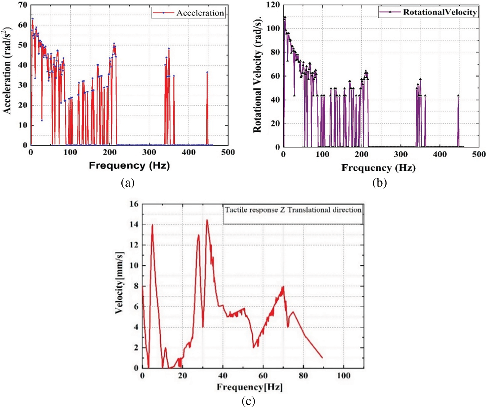
Figure 8: Experimental modal analysis. (a) Acceleration, (b) Velocity, (c) Tactile response Z-Translational direction
The objective of this study is to introduce the concept of substructuring method and tactile response phenomenon in the vibrational analysis of a small horizontal axis wind turbine in its working condition. Tactile response for the wind turbine has been modelled and characterized with the experimental data. Finite element model of the wind turbine model gives the vibrational characteristics and other dynamic properties. The fore/aft and twist mode of the blade helps to analyze where vibrational defects occur during its working. Tactile responses in rotational and translational directions have been characterized with dynamic properties obtained. The torsional vibration has been integrated with structural dynamic properties to calculate tactile response and NVH.
Funding Statement:The authors received no specific funding for this study.
Conflicts of Interest:The authors declare that they have no conflicts of interest to report regarding the present study.
References
1. Arteaga-López, E., Ángeles-Camacho, C., Bañuelos-Ruedas, F. (2019). Advanced methodology for feasibility studies on building-mounted wind turbines installation in urban environment: Applying CFD analysis. Energy, 167, 181–188. DOI 10.1016/j.energy.2018.10.191. [Google Scholar] [CrossRef]
2. Awadallah, M., El-Sinawi, A. (2020). Effect and detection of cracks on small wind turbine blade vibration using special kriging analysis of spectral shifts. Measurement, 151, 107076. DOI 10.1016/j.measurement.2019.107076. [Google Scholar] [CrossRef]
3. Baik, S., Lee, J., Suh, J. (2003). A study on the characteristics of vibration in seat system. Noise & Vibration Conference and Exhibition, SAE Technical Paper Series, pp. 2003-01-1603. Traverse City, Michigan. [Google Scholar]
4. Chen, F., Chen, Y., Hua, H. (2019). Vibration analysis of a submarine elastic propeller-shaft-hull system using FRF-based substructuring method. Journal of Sound and Vibration, 443, 460–482. DOI 10.1016/j.jsv.2018.11.053. [Google Scholar] [CrossRef]
5. Chen, X., Yang, Y., Cui, Z., Shen, J. (2019). Vibration fault diagnosis of wind turbines based on variational mode decomposition and energy entropy. Energy, 174, 1100–1109. DOI 10.1016/j.energy.2019.03.057. [Google Scholar] [CrossRef]
6. Choi, K. K., Shim, I., Wang, S. (1997). Design sensitivity analysis of structure-induced noise and vibration. Journal of Vibration and Acoustics, 119, 173–179. DOI 10.1115/1.2889699. [Google Scholar] [CrossRef]
7. Craig, R., Bampton, M. (1968). Coupling of substructures for dynamic analysis. Journal of American Institute of Aeronautics and Astronautics, 6, 313–1319. [Google Scholar]
8. Craig, R. R., Kurdila, A. J. (2006). Fundamentals of structural dynamics. Hoboken, New Jersey: John Wiley & Sons. [Google Scholar]
9. Fagiani, R., Massi, F., Chatelet, E., Berthier, Y., Akay, A. (2011). Tactile perception by friction induced vibrations. Tribology International, 44, 1100–1110. DOI 10.1016/j.triboint.2011.03.019. [Google Scholar] [CrossRef]
10. Géradin, M., Rixen, D. J. (2014). Mechanical vibrations: Theory and application to structural dynamics. UK: John Wiley & Sons. [Google Scholar]
11. Hage, A., Szatkowski, A., Li, Z. (2007). Improving low frequency torsional vibrations NVH performance through analysis and test. Noise & Vibration Conference and Exhibition, pp. 1771–1779, SAE Transactions St. Charles, Illinois. [Google Scholar]
12. Hansen, M. O. (2000). Aerodynamics of wind turbines: Rotors, loads and structure. United Kingdom: Earthscan. [Google Scholar]
13. Hu, C. (2019). A novel method for damping of complex mechanical systems. Sound & Vibration, 53(5), 199–206. [Google Scholar]
14. Flodén, O., Sandberg, G., Persson, K. (2018). Reduced order modelling of elastomeric vibration isolators in dynamic substructuring. Engineering Structures, 155, 102–114. DOI 10.1016/j.engstruct.2017.11.001. [Google Scholar] [CrossRef]
15. Jokar, H., Mahzoon, M., Vatankhah, R. (2020). Dynamic modeling and free vibration analysis of horizontal axis wind turbine blades in the flap-wise direction. Renewable Energy, 146, 1818–1832. DOI 10.1016/j.renene.2019.07.131. [Google Scholar] [CrossRef]
16. Klerk, D. D., Rixen, D. J., Voormeeren, S. (2008). General framework for dynamic substructuring: History, review and classification of techniques. Journal of American Institute of Aeronautics and Astronautics, 46, 1169–1181. DOI 10.2514/1.33274. [Google Scholar] [CrossRef]
17. Kullaa, J. (2016). Virtual sensing of structural vibrations using dynamic substructuring. Mechanical Systems and Signal Processing, 79, 203–224. DOI 10.1016/j.ymssp.2016.02.045. [Google Scholar] [CrossRef]
18. Kumar, M. S., Krishnan, A., Vijayanandh, R. (2018). Vibrational fatigue analysis of NACA 63215 small horizontal axis wind turbine blade. Materials Today: Proceedings, 5, 6665–6674. [Google Scholar]
19. Liu, X., Lu, C., Liang, S., Godbole, A., Chen, Y. (2017). Vibration-induced aerodynamic loads on large horizontal axis wind turbine blades. Applied Energy, 185, 1109–1119. DOI 10.1016/j.apenergy.2015.11.080. [Google Scholar] [CrossRef]
20. Mabrouk, I. B., El Hami, A., Walha, L., Zghal, B., Haddar, M. (2017). Dynamic vibrations in wind energy systems: Application to vertical axis wind turbine. Mechanical Systems and Signal Processing, 85, 396–414. DOI 10.1016/j.ymssp.2016.08.034. [Google Scholar] [CrossRef]
21. Mohammadi, A., Abdelkhalek, M., Sadrafshari, S. (2020). Resonance frequency selective electromagnetic actuation for high-resolution vibrotactile displays. Sensors and Actuators A: Physical, 302, 111818. DOI 10.1016/j.sna.2019.111818. [Google Scholar] [CrossRef]
22. O’Brien, J., Young, T., O’Mahoney, D., Griffin, P. (2017). Horizontal axis wind turbine research: A review of commercial CFD, FE codes and experimental practices. Progress in Aerospace Sciences, 92, 1–24. DOI 10.1016/j.paerosci.2017.05.001. [Google Scholar] [CrossRef]
23. Petyt, M. (2010). Introduction to finite element vibration analysis. USA: Cambridge University Press. [Google Scholar]
24. Voormeeren, S., van der valk, P. C., Rixen, D. (2011). Generalized methodology for assembly and reduction of component models for dynamic substructuring. Journal of American Institute of Aeronautics and Astronautics, 49, 1010–1020. DOI 10.2514/1.J050724. [Google Scholar] [CrossRef]
25. Pradeepkumar, S., Nagaraj, P. (2021). Dynamic substructuring method for vibration analysis of complex structures. Journal of Vibration Engineering & Technologies, 10(1), 313–333. DOI 10.1007/s42417-021-00378-8. [Google Scholar] [CrossRef]
26. Wood, D. (2011). Small wind turbines: Analysis, design and application. Verlag, London: Springer. [Google Scholar]
27. Wu, N., Lu, K., Jin, Y., Zhang, H., Chen, Y. (2020). The applications of order reduction methods in nonlinear dynamic systems. Sound & Vibration, 54(2), 113–125. DOI 10.32604/sv.2020.09783. [Google Scholar] [CrossRef]
Cite This Article
 Copyright © 2022 The Author(s). Published by Tech Science Press.
This work is licensed under a Creative Commons Attribution 4.0 International License , which permits unrestricted use, distribution, and reproduction in any medium, provided the original work is properly cited.


 Submit a Paper
 View Full Text
 Download PDF
 Downloads
 Citation Tools