
 Submit a Paper
 Propose a Special lssue
 Open Access
ARTICLE

Effects of Repair Grouting and Jacketing on Corrosion Concrete Using Ultrasonic Method
1 Magister of Civil Engineering, Universitas Muhammadiyah Yogyakarta, Bantul, 55183, Indonesia
2 Department of Civil Engineering, Faculty of Engineering, Universitas Muhammadiyah Yogyakarta, Bantul, 55183, Indonesia
* Corresponding Author: Ahmad Zaki. Email:
Structural Durability & Health Monitoring 2025, 19(2), 265-284. https://doi.org/10.32604/sdhm.2024.053084
Received 24 April 2024; Accepted 15 July 2024; Issue published 15 January 2025
 View Full Text
 Download PDF
Abstract
Concrete is one of the most important elements in building construction. However, concrete used in construction is susceptible to damage due to corrosion. The influence of corrosive substances causes changes in the reinforcing steel and affects the strength of the structure. The repair method is one approach to overcome this problem. This research aims to determine the effect of grouting and jacketing repairs on corroded concrete. The concrete used has dimensions of 15 cm × 15 cm × 60 cm with planned corrosion variations of 50%, 60%, and 70%. The test objects were tested using the Non-Destructive Testing (NDT) method using Ultrasonic Pulse Velocity (UPV). The test results show that the average speed of normal concrete is 5070 m/s, while the lowest average speed is 3070 m/s on the 70% planned corrosion test object. The test object was then given a load of 1600 kgf. At this stage, there is a decrease in speed and wave shape with the lowest average speed obtained at 2753 m/s. The repair method is an effort to restore concrete performance by using grouting and jacketing. Grouting is done by injecting mortar material into it. Jacketing involves adding thickness to the existing concrete layer with additional layers of concrete. After improvements were made, there was an improvement in the UPV test, with a peak speed value of 4910 m/s. Repairing concrete by filling cracks can improve concrete continuity and reduce waveform distortion, thereby increasing wave propagation speed.Keywords
Development in the construction is inseparable from the use of concrete [1,2]. Concrete is the most widely used construction material and is considered the most essential element because it has many advantages, such as being easily shaped, durable, and readily available [3,4]. However, these materials degrade over time, one of which is through corrosion of the reinforcement [2,5–7]. Corrosion in reinforced concrete (RC) is caused by the interaction between the alkaline properties of reinforcing steel and an acidic environment, resulting in corrosion of the reinforcement [8]. Reinforcement that is alkaline with a pH of ± 12.5 interacts with an environment that has a high acid content, causing a decrease in the pH of the concrete and corrosion [9–11]. The influence of corrosive substances will affect the weight and diameter of the reinforcement, thus reducing the performance of RC components and diminishing the building’s service life [12–14]. If repairs are not carried out, corrosion will develop rapidly, causing damage to the concrete covering layer and exposing steel parts to direct attack by environmental conditions [15].
Knowledge of structural strengthening technology, including repairs, is required to overcome the reduction in the service life of concrete due to structural damage [16,17]. Repair is to restore the strength of a structure that has experienced a decline so that it returns to its original state [18,19]. Concrete strengthening techniques are increasingly developing in terms of materials and strengthening methods, including jacketing and grouting techniques. Jacketing is a method of coating the surface of the concrete by removing the damaged part, and then the concrete is recast using high-quality concrete as a coating and plaster [19]. The concept of this method is to add reinforcement and enlarge the dimensions of reinforcement in RC [20]. Grouting is an effort to repair damaged concrete surfaces so that they can return to their original condition using grout materials that are cement and water, with or without the addition of aggregate [21].
Evaluation is very important to monitor the performance of repair products in an effort to cover concrete damage [22,23]. One method that can be used is the NDT (Non-Destructive Testing) method, one of which is UPV (Ultrasonic Pulse Velocity) [24]. The use of NDT techniques has many advantages in that it can monitor conditions without causing additional damage, is cost efficient and speedy in providing results [25–27]. UPV is an NDT technique used to identify cracks and can be used to investigate changes caused by repair ability [22–24]. Previous studies have shown that self-healing during freeze/thaw cycles can be monitored by UPV with parameters correlated to the level and stage of damage [28,29]. This test can evaluate the effectiveness of crack treatment as well as indicate changes in structural properties during the healing evolution [30,31].
In previous research, the use of UPV technique was limited to concrete defect or deterioration detection. However, further analysis or monitoring of the effectiveness of repair methods, such as grouting or jacketing, has not been the main focus of the other research. In other words, although UPV is used to detect defects, it has not been widely used to monitor or evaluate the repair process itself. In this study, UPV was used not only to detect defects but also to monitor the repair process and evaluate the overall effectiveness of the repair method. Thus, UPV becomes a more holistic tool in supporting the analysis and monitoring of the condition of reinforced concrete structures.
In this section, we will explain in detail the materials used in the research, as well as the experimental procedures applied to collect the necessary data and information. This will include a description of the type of concrete used, other material specifications, and the steps taken in the tests and analyzes performed.
The materials used are the main components of concrete, such as coarse aggregate, fine aggregate, cement, and water, as seen in Fig. 1. The fine aggregate is sourced from Progo River, Yogyakarta, with a size range of 4.75 to 0.0075 mm (Fig. 1a). The coarse aggregate used comes from Clereng, Kulon Progo, Yogyakarta with a maximum size of 19 mm (Fig. 1b). The cement used is Type I Portland Cement. In grouting and jacketing work, an additional binding material, Sika Sikacim Bonding Adhesive, is used (Fig. 1c). The aggregates are tested to determine their specifications. The tests conducted include gradation, fineness modulus, material finer than the No. 200 sieve, specific gravity, water absorption, bulk density, moisture content, and abrasion. These tests are conducted based on SNI 03-4142-1996 [32]. After obtaining the test result data, it can be used to analyze the mix requirements for the test specimen using ACI 211.1-91 [33]. After obtaining the test result data, it can be used to analyze the mix requirements for the test specimen using ACI 211.1-91 with a compressive strength (fc’) of 30 MPa. Table 1 shows the material requirements for each specimen.
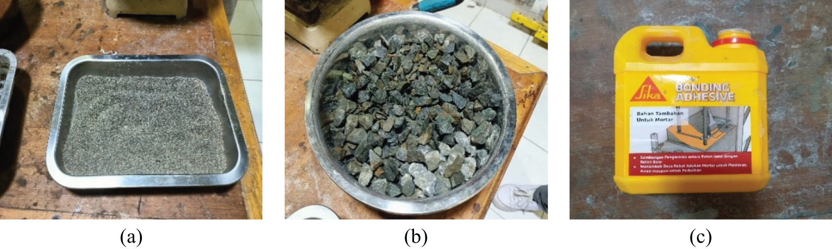
Figure 1: (a) Fine aggregate (b) Coarse aggregate, and (c) Bonding adhesive
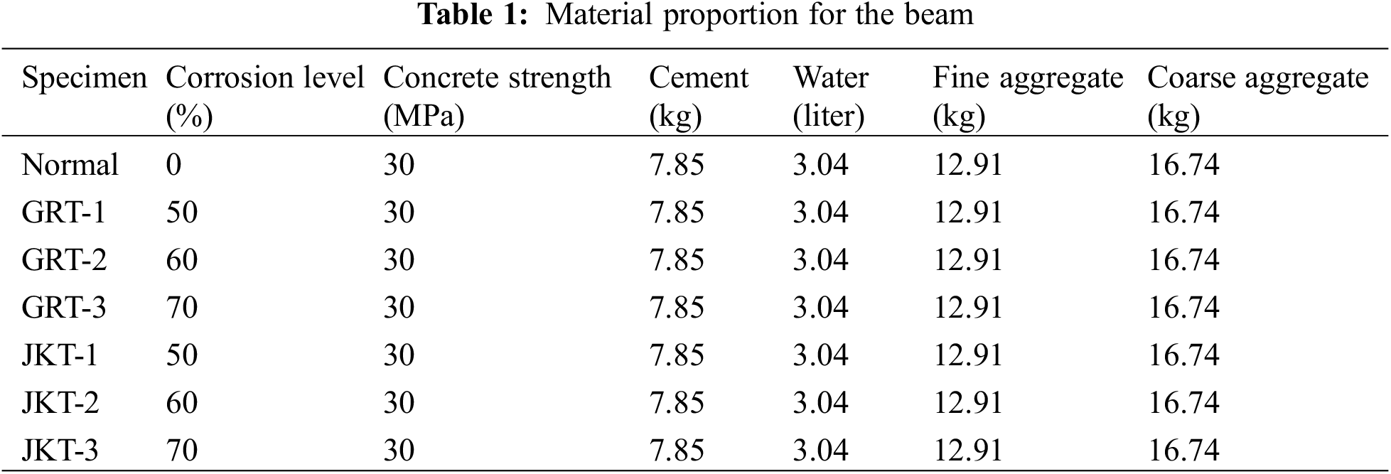
The table above displays specimens with names indicating the type of concrete repair and design corrosion percentage. Specimens with the code “GRT” indicate concrete using the grouting technique, while “JKT” uses the jacketing method. Numbers 1–3 represent the percentage of corrosion rate as “1” is 50%, “2” is 60% and “3” is 70%. In this study, 15 cm × 15 cm × 60 cm beams are used as the test specimens with a reinforcement configuration as in Fig. 2. These dimensions were chosen because they are close to the dimensions of simple house columns commonly used in residential building construction. On the other hand, selecting this size also considers the ease of the beam manufacturing and testing process, as well as compatibility with available laboratory equipment. The curing period is 28 days, achieved by immersing the samples in a curing tank. There will be a total of 7 samples for three variations of corrosion levels. The test specimens will be divided into pre-corrosion and post-corrosion specimens, and all specimens will be tested for flexural strength and non-destructive testing (NDT). The slump value is 14 cm. The slump test is based on SNI 1972-2008. This testing is conducted to determine the workability of the mix for each sample.
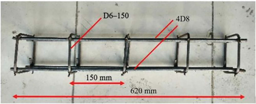
Figure 2: Configuration of reinforcing bar spacing
The 28-day-old concrete specimens underwent a curing process and then a corrosion process. The corrosion process in concrete requires a very long time, so corrosion acceleration techniques are carried out using impressed current techniques [34]. The galvanostatic method is used based on ASTM G1-03 [35] and ASTM G31-72 [36], with the equipment used in the form of a DC power supply [37], as shown in Fig. 3. The cable is connected to the concrete inner reinforcement (anode) and the concrete outer reinforcement (cathode) to the same DC Power Supply. The cables attached to the reinforcement in the concrete are connected to the positive terminal of the DC Power Supply. Instead, the cable attached to the sacrificial reinforcement is connected to the negative terminal of the DC Power Supply. The specimen that has been connected to the DC Power Supply is then immersed in a tank of 5% NaCl solution. This is done for a certain duration calculated based on Faraday’s Law, adjusted to achieve the planned corrosion levels of 50%, 60%, and 70%. This corrosion percentage is assumed to obtain the results of cracking due to corrosion in concrete. Thus, the corrosion rate selected reflects the real conditions that a concrete structure may experience in a particular environment over a period of time. Corrosion acceleration was carried out in this test by reviewing the percentage of mass loss of the specimen in the form of steel reinforcement after corrosion and before corrosion. The accelerated corrosion scheme is shown in Fig. 3.
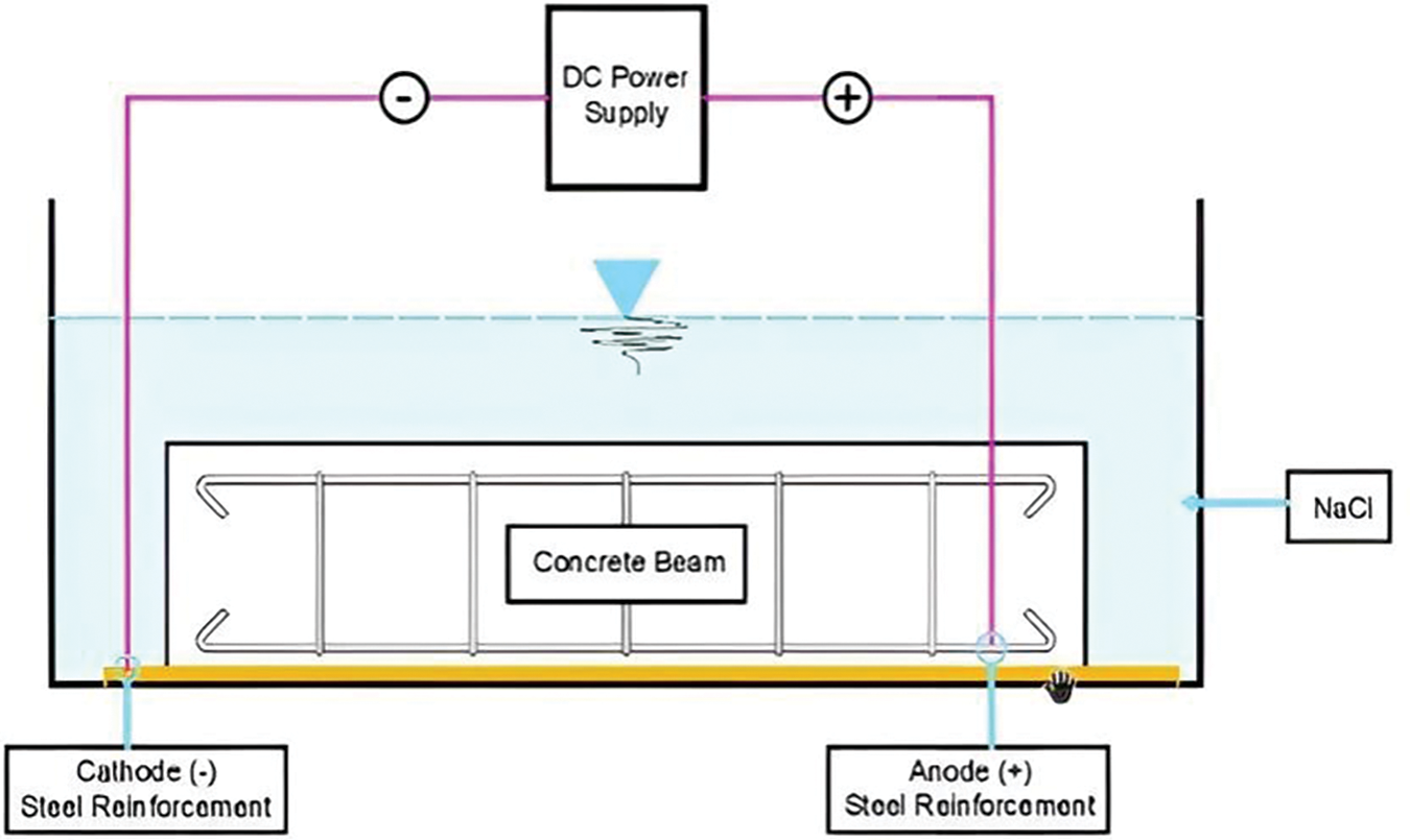
Figure 3: Corrosion acceleration test scheme on structural materials
Flexural testing consists of two stages: first, testing is carried out on normal concrete to obtain initial flexural strength values; secondly, tests are carried out after the concrete repair process to compare the effect of the repair. Fig. 4 clearly illustrates the flexural strength testing process, including the position of the loading point and the cracks that occur during the test. Flexural strength tests are carried out based on SNI 4431:2011 [38]. This test method uses two loading points placed between the beam spans. The load was increased gradually using a universal testing machine until the beam experienced cracks on its surface. An example of the difference in the crack pattern in the structure before and after the repair is shown in Fig. 5.
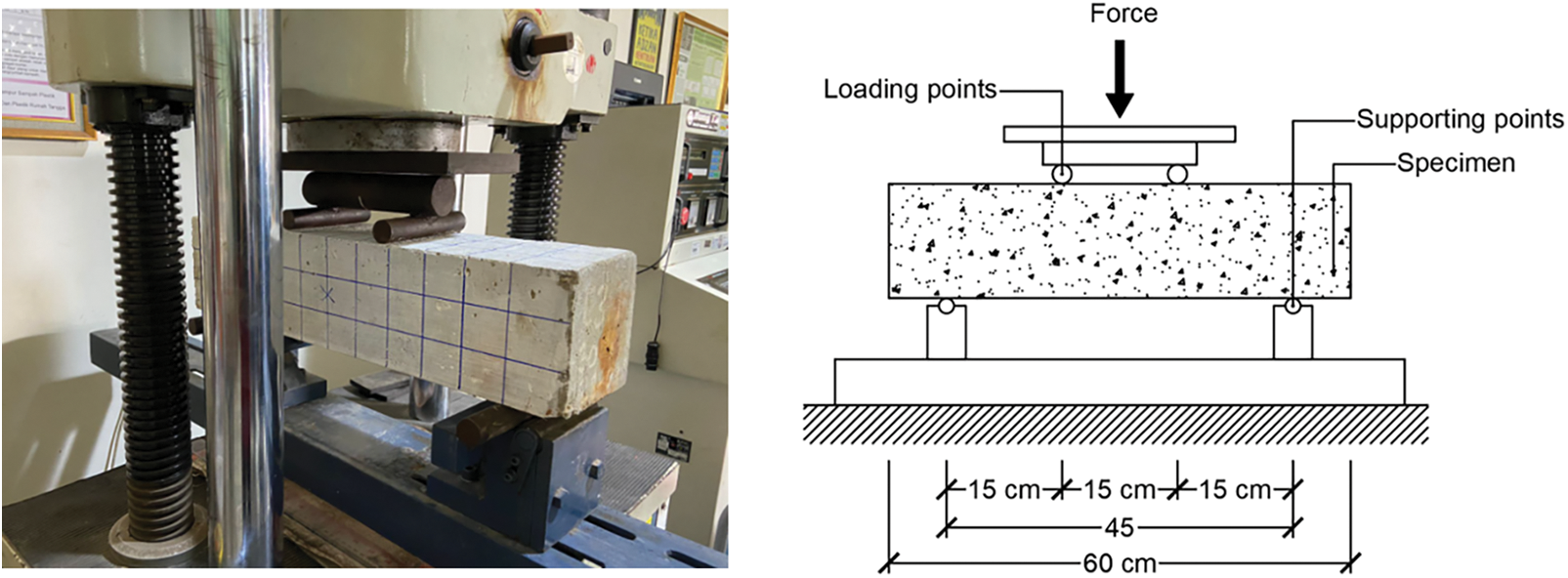
Figure 4: Flexural strength testing
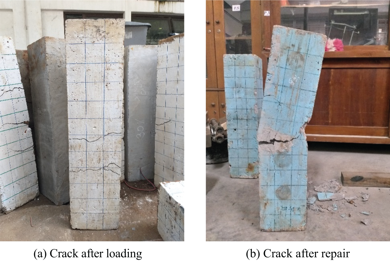
Figure 5: Differences in cracks before and after repair
The loading process before strengthening is carried out by weighing the concrete until the surface experiences cracks. The loading method used to control cracks is carried out by applying the load gradually. The load increases slowly until the first cracks appear on the concrete surface. This approach is used to control crack development better and ensure that loading is applied consistently to produce the desired crack condition before repair steps.
2.4 Ultrasonic Pulse Velocity (UPV)
The UPV test is a way to estimate concrete hardness based on the relationship between wave velocity through the concrete medium [39,40]. The UPV method measures the travel time of ultrasonic waves through a specimen, which is influenced by material condition, integrity, and potential defects such as corrosion [41]. The electrical signals are converted into mechanical vibrations (transmission mode), and these mechanical vibrations are then transformed back into electrical signals by the transducer [42]. UPV testing is carried out in 4 stages, i.e., in normal conditions, after accelerated corrosion, after loading, and after repair. Fig. 6 provides details of the side section of the UPV test.
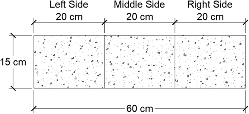
Figure 6: Illustration of side division in the UPV test
In its implementation, UPV testing is carried out in 3 methods.
Direct transmission is a configuration in which the transmitter and receiver transducers are placed simultaneously on opposing surfaces of the concrete [43], as shown in Fig. 7.
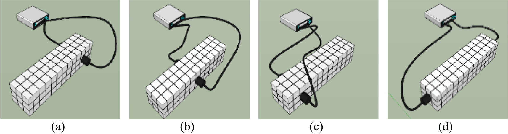
Figure 7: Direct method (a) Placement 1, (b) Placement 2, (c) Placement 3, (d) Placement 4
The semi-direct testing method is performed on each specimen by placing the transmitter on the side and top of the specimen, as shown in Fig. 8.
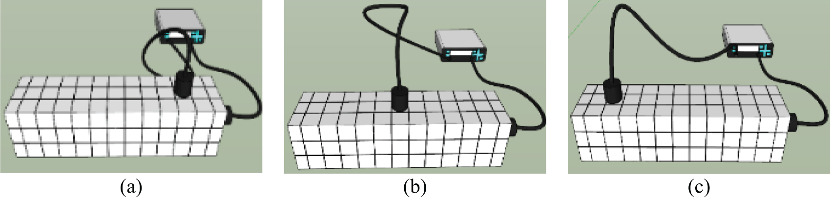
Figure 8: Semi-direct method (a) Placement 1, (b) Placement 2, (c) Placement 3
The indirect method of the three testing methods available, the indirect method is known to provide less reliable results because the received signal amplitude can decrease by up to 3% [44] and is only used if the specimen’s surface is accessible [45], especially when it is crucial to determine the depth of cracks or the presence of multiple layers in the same element [43], the indirect method is shown in Fig. 9.
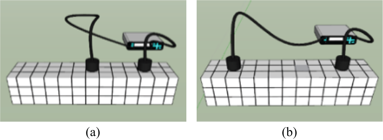
Figure 9: Indirect method (a) Placement 1, (b) Placement 2
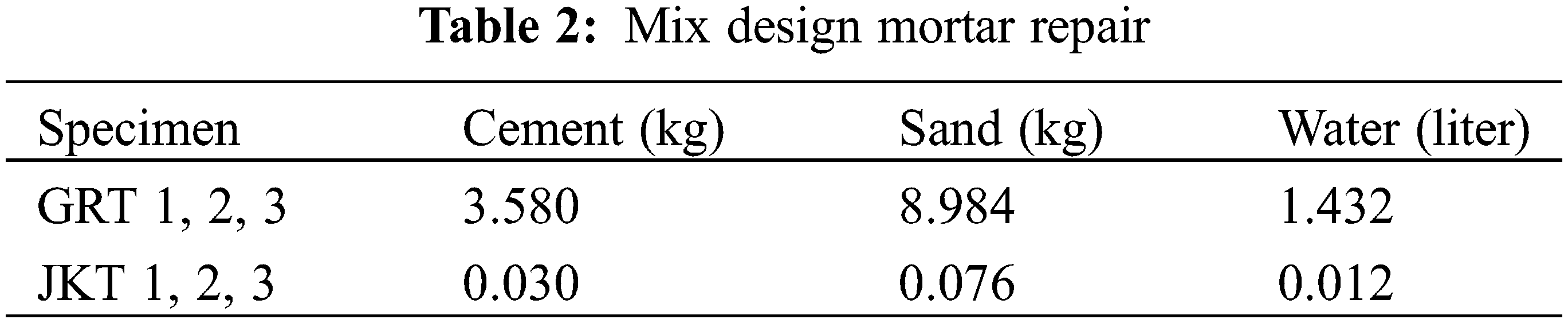
Refer to the concrete repair process of filling voids within the concrete structure with grout material, as shown in Fig. 10. This approach can be implemented by utilizing either Portland cement grout or opting for chemical grouting [46]. Grouting using Portland cement has proven to be highly effective in addressing wide cracks, especially in structures like dams and thick concrete walls [18,47]. The crack is cleaned and flushed before the entire area is filled with grouting. The composition of putty can be in the form of a paste consisting of only cement and water or as mortar involving a mixture of cement, sand, and water, depending on the width of the cracks in that structural part, as shown in Table 2. Meanwhile, the water-to-cement ratio should be kept as low as possible to achieve high strength with minimal shrinkage [48].
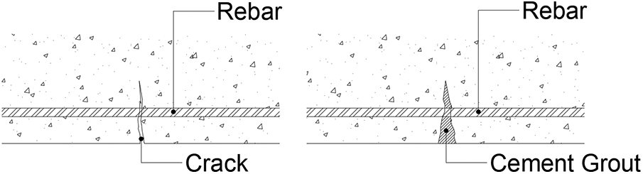
Figure 10: Scheme for implementing the grouting method
The jacketing of reinforced concrete (RC) has become a common solution for strengthening and repairing RC columns that are deficient or damaged, as shown in Fig. 11. It illustrates the jacketing method. In the reinforcement of RC, the column section is strengthened by adding a new layer of concrete or reinforced mortar along part or the entire length through the casting process. Additionally, the success of RC jacketing depends on achieving a better bond between the damaged column and the additional jacket. This can be achieved by providing a rough texture on the surface using a hammer and chisel [43].
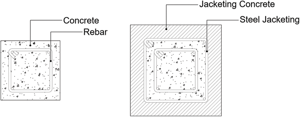
Figure 11: Illustration before and after jacketing
In this section, the results of the research will be presented and discussed in detail. Data that has been collected through various testing methods will be analyzed to identify significant relationships. The test results will be compared with previous research to assess the contributions and innovations offered by this study. This section aims to provide an in-depth understanding of the research findings and their relevance in scientific and practical contexts.
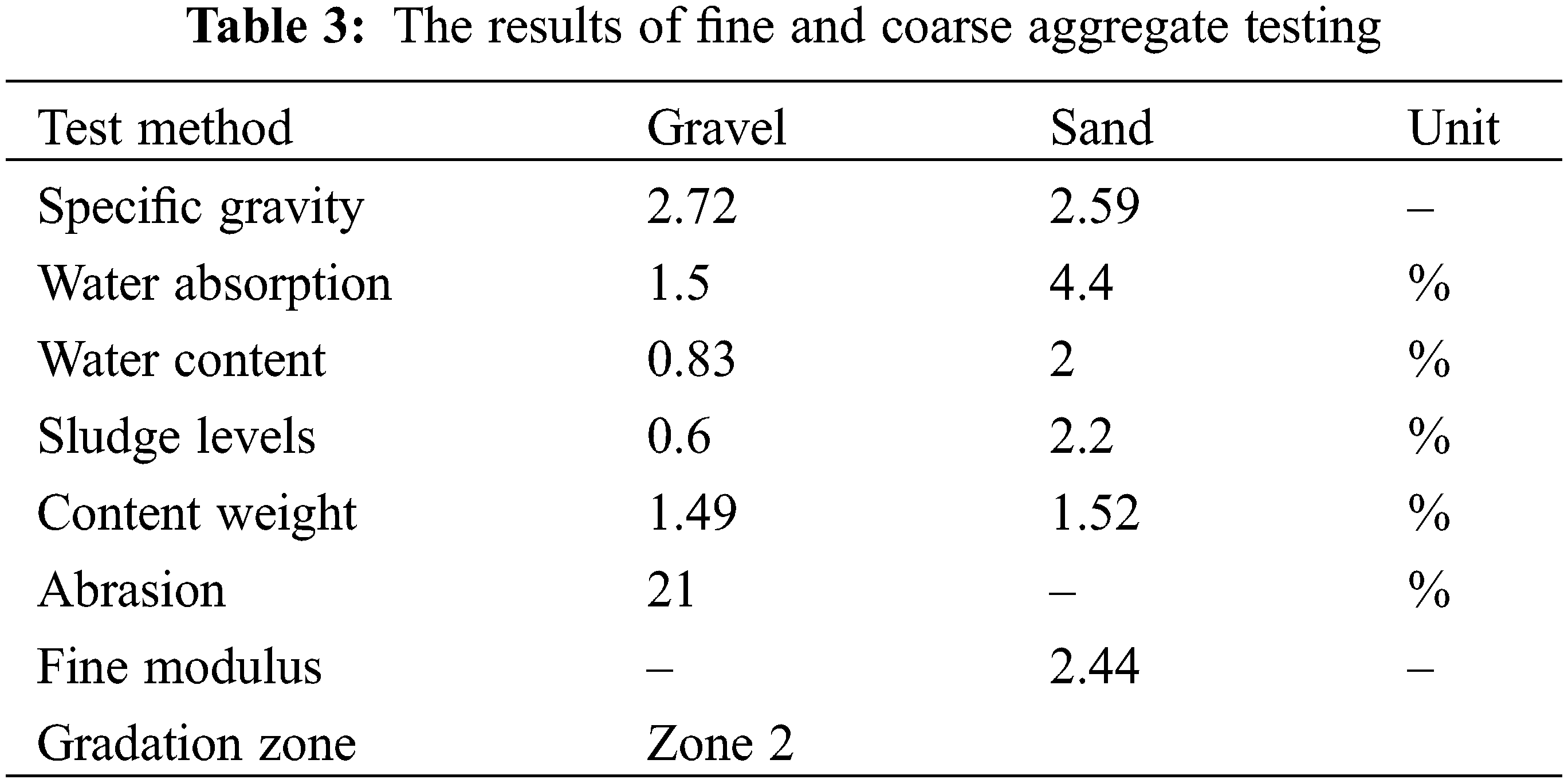
Selecting aggregate specifications is the most important thing before starting the study. In this section, the results of the aggregate specifications used in this research will be presented. Various important physical and mechanical characteristics will be described in the aggregate specifications. The results obtained from aggregate testing will be explained in detail, including analysis of water content, sludge levels, and other relevant parameters. This data is very important to understand so that the properties of the aggregate can influence the mechanical properties and durability of the concrete produced. Table 3 shows the results of tests carried out on coarse and fine aggregates.
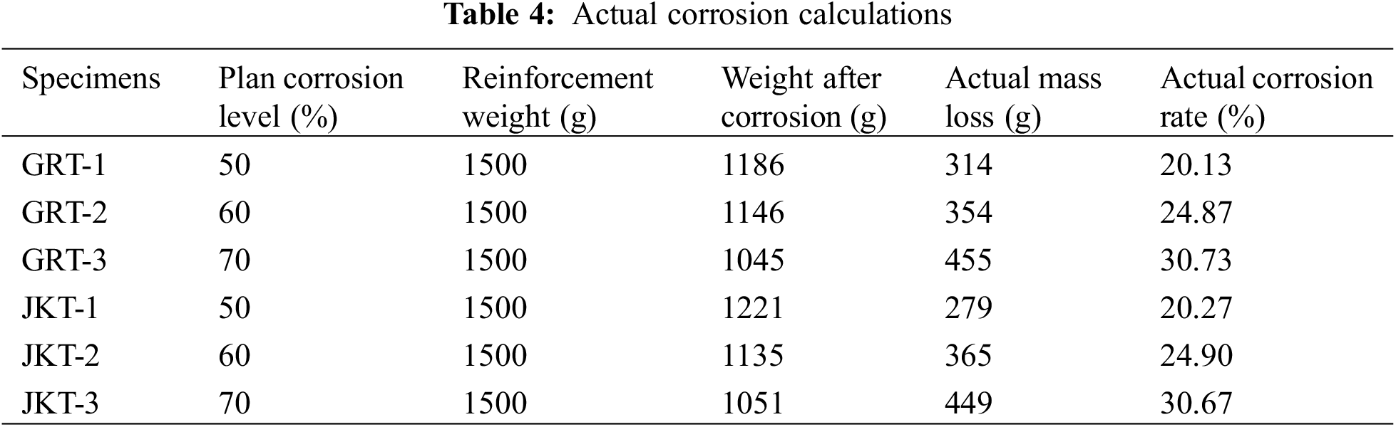
Actual corrosion calculations are carried out to understand the rate of corrosion that occurs in reinforced concrete under experimental conditions. Table 4 shows the actual corrosion calculation results for each specimen. There is a difference between the level of corrosion estimated by Faraday’s Law and the actual level of corrosion. This occurs because there is resistance or resistance to the movement of ions from the anode to the cathode. This obstacle is thought to originate from the concrete surface, which is in contact with the Styrofoam so that the NaCl solution cannot wet the surface. The physical binding resistance of chloride ions during the accelerated corrosion process greatly influences the process [49]. The difference in mass loss between the actual mass and the calculated mass is due to the calculated mass based on Faraday’s Law, which is assumed to be general corrosion, whereas in reality, there is some local corrosion [50].
This test was carried out to determine the flexural strength value of concrete after repairs using grouting and jacketing methods. In this test, a concentrated load system is applied at two loading points to simulate realistic conditions in the repaired concrete structure. This method allows us to measure the extent to which the repair can restore or even increase the flexural strength of the concrete. The flexural strength test results obtained from this experiment can be seen in detail in Table 5.
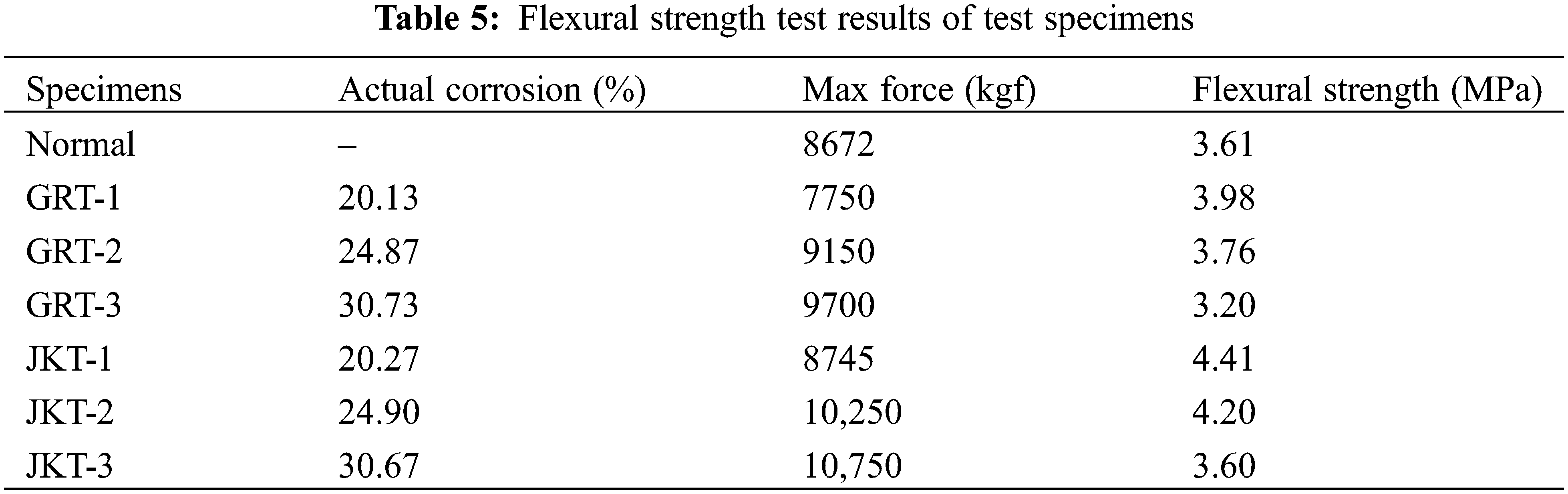
With increasing corrosion percentage, there is a significant decrease in the flexural strength value of the specimen. This shows that there is a negative correlation between the level of corrosion and the flexural strength of the test object after repair. The higher the percentage of corrosion, the lower the flexural strength obtained, indicating that corrosion has a detrimental impact on the structural integrity of the test specimen [51]. Table 5 and Fig. 12 show the results of the flexural strength of the test specimen after repair. In this context, the lowest flexural strength value, 3.20 MPa, was achieved at the highest corrosion level, namely 30.73%. On the other hand, the highest value of flexural strength, namely 4.41 MPa, was observed at a lower corrosion percentage, namely 20.27%.
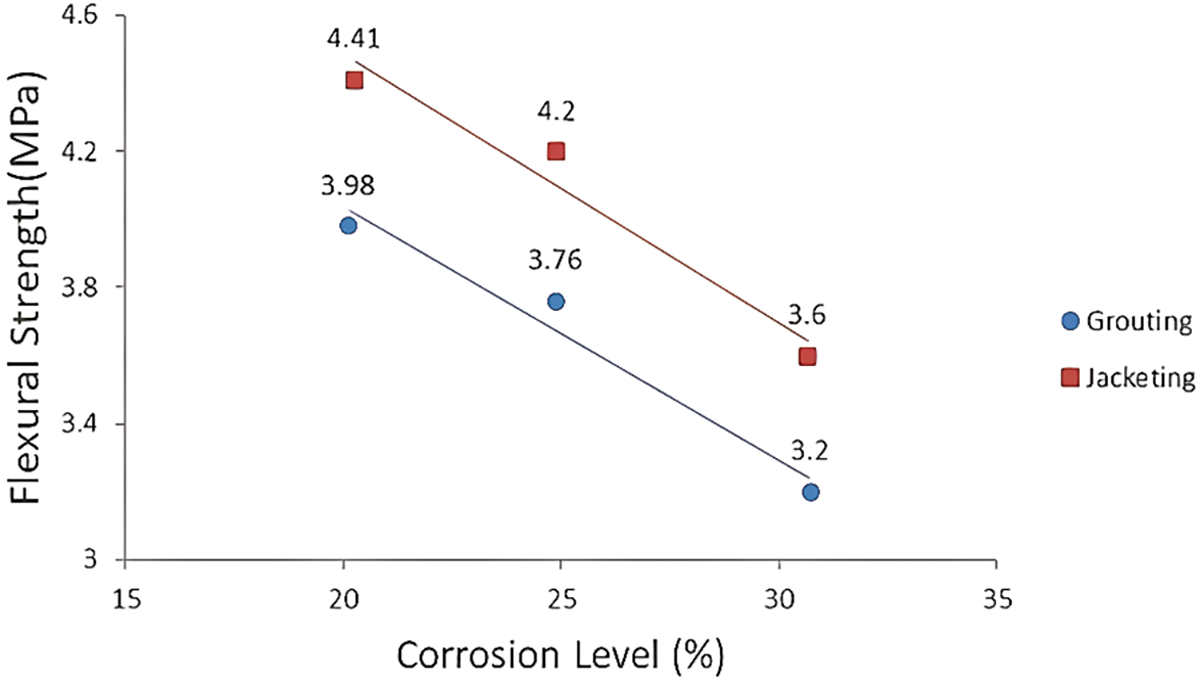
Figure 12: Comparison of flexural strength to corrosion level
Concrete using the Repair Jacketing method, which involves adding structural dimensions, effectively increases the overall strength of the structure. This process results in a more thorough repair by adding an additional layer of solidity [52]. Meanwhile, grouting methods tend to only fill gaps or cracks in the concrete with additional materials. Although this process can provide improvements, it does not give the significant increase in overall structural strength that the Jacketing method does. The comparison given in Fig. 13 confirms that the Repair Jacketing method has advantages in increasing the flexural strength value of the test object after repair compared to the grouting method. This indicates that the jacketing method is more effective in repairing and strengthening damaged concrete structures.
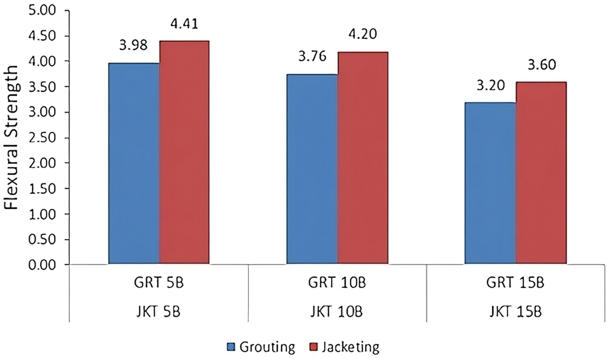
Figure 13: Comparison of flexural strength of grouting and jacketing
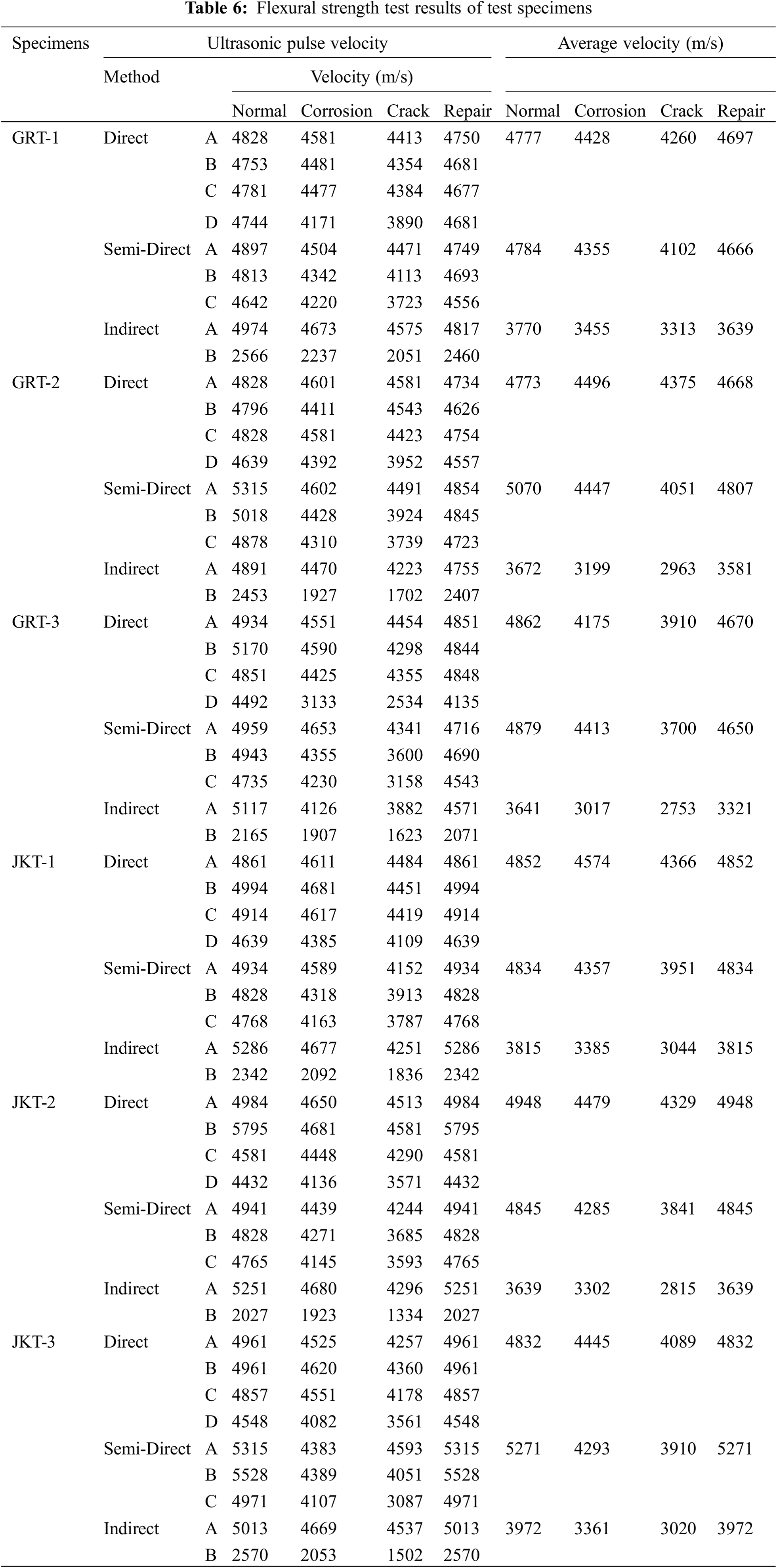
This test is carried out in four stages: pre-corrosion, post-corrosion, post-loading, and post-repair concrete. For each stage, testing using the Ultrasonic Pulse Velocity (UPV) method is applied with three approaches: direct, semi-direct, and indirect methods. Each technique is carried out at three test points on each test object, namely at the right end, middle and left end of the test object, to ensure the data taken is representative and accurate. The UPV test results on each test object are summarized in Table 6, which shows the variability and comparison of results between the various test stages.
3.4.1 The Relationship between Corrosion Level and Velocity
Testing UPV at different levels of corrosion resulted in measurements illustrated in Fig. 14. The velocity decreased after the concrete underwent acceleration processes with varying degrees of corrosion. The higher the percentage of corrosion applied, the lower the velocity generated. The average velocity obtained after corrosion testing yielded a value of 4000 m/s. This aligns with the study conducted by Almashakbeh et al. [53], where changes in UPV values tend to follow an increase in the level of corrosion.
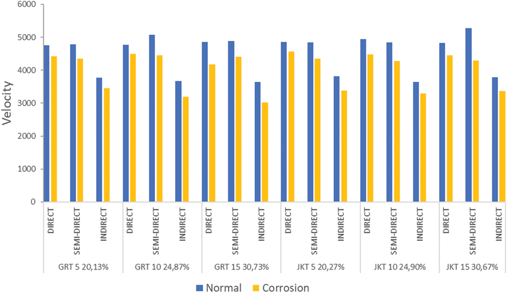
Figure 14: Graph of the relationship between corrosion level and velocity value
3.4.2 Relationship between Corrosion Level and Ultrasonic Waveform
An increase in corrosion values in concrete structures can cause a decrease in the quality of the concrete material and can weaken the structure as a whole. Cracks that occur in concrete are a visual sign of damage caused by steel corrosion. The higher the level of corrosion, the more cracks will occur [54], and this can weaken the bond between the concrete materials and steel reinforcement. as shown in Fig. 15. It explains that there is a continuous decrease in signal along with increasing corrosion acceleration values.
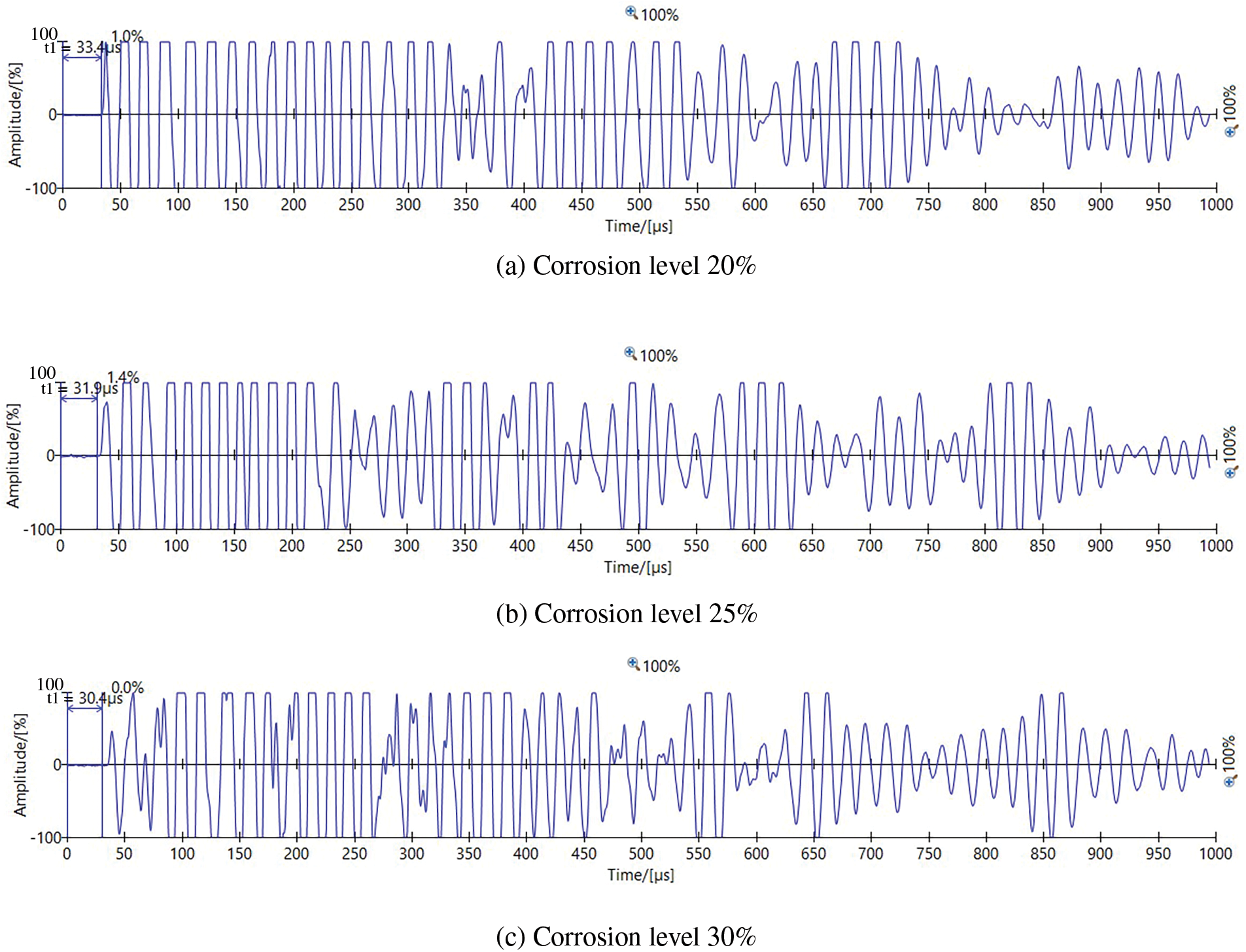
Figure 15: Waveform variations in corrosion. (a) 20% corrosion, (b) 25% corrosion, (c) 30% corrosion
3.4.3 Comparison of Velocity Values after Loading
Corrosion in concrete causes degradation, which results in cracks and irregularities in the composition of the material. This creates obstacles for ultrasonic waves, which undergo distortion or reflection when penetrating damaged structures. The wave propagation speed observed in Fig. 16 shows a decrease after the loading process. This decrease is caused by increasing damage to the concrete structure along with the applied load. Thus, additional damage due to loading worsens the condition of the concrete, increases the resistance to ultrasonic waves, and reduces the wave propagation speed significantly.
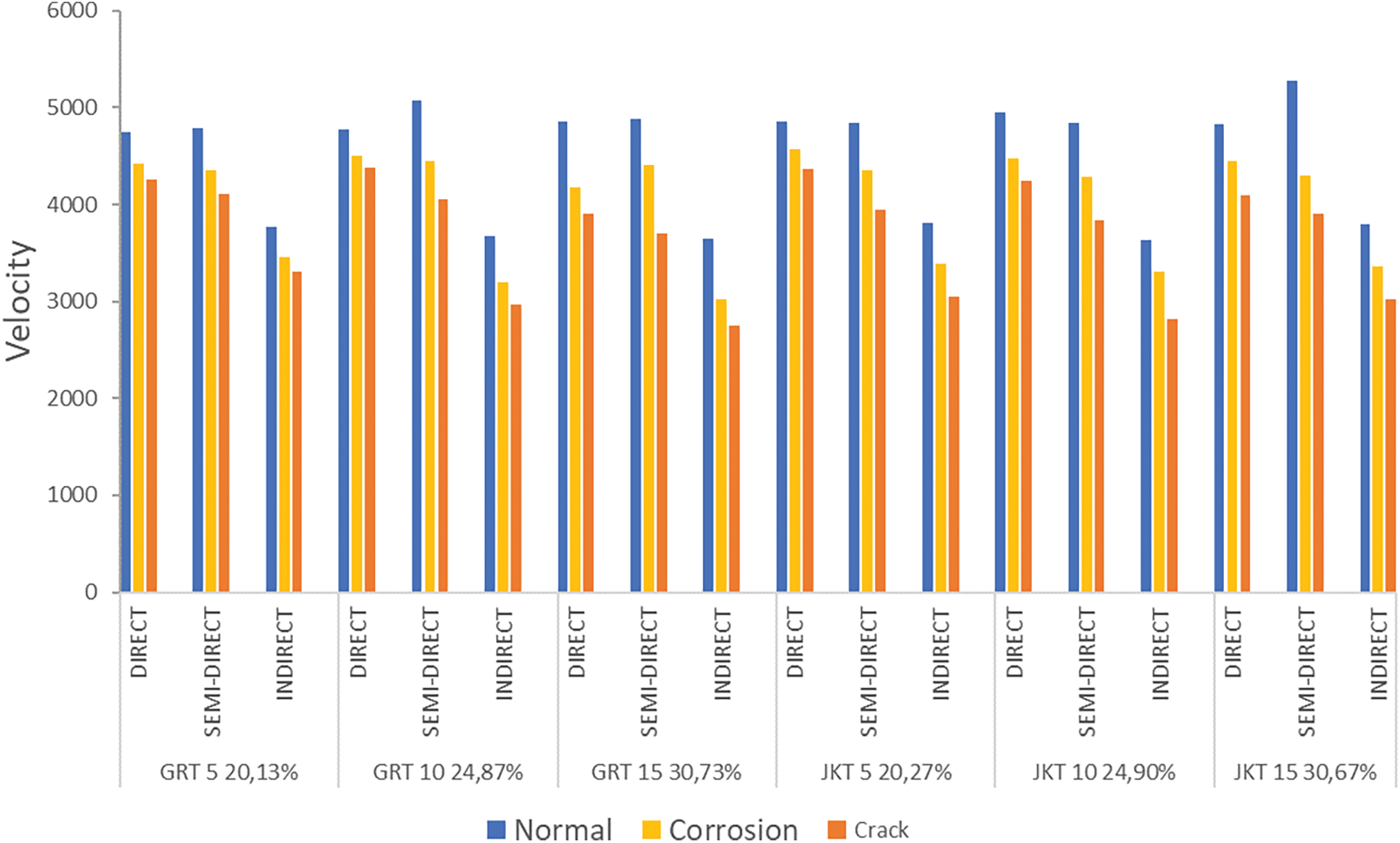
Figure 16: Differences in velocity values in concrete conditions after loading
3.4.4 Comparison of Velocity after Grouting Repair
Grouting is a repair technique used to fill and seal cracks in concrete. By reducing the number of cracks, ultrasonic waves experience less resistance when passing through the concrete, thereby increasing the UPV value. However, even though there has been improvement, the UPV value after the grouting process has not yet reached the same value as concrete under normal conditions, as shown in Fig. 17. Therefore, although grouting can increase the UPV value, it is important to note that grouting is only a corrective action and may not always return the concrete completely to its original condition.
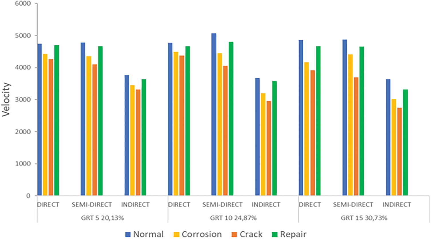
Figure 17: Differences in velocity values in structures before and after repair with grouting method
3.4.5 Comparison of Velocity after Jacketing Repair
Jacketing is a method involving the addition of additional layers to existing concrete structures to enhance their strength and resistance to external loads or forces. Fig. 18 displays the velocity values after the repair. The application of jacketing to concrete can have a significant influence on the UPV values. However, despite the improvement, the ultrasonic wave velocity values after the jacketing process may not reach the same level as those of concrete in normal conditions.
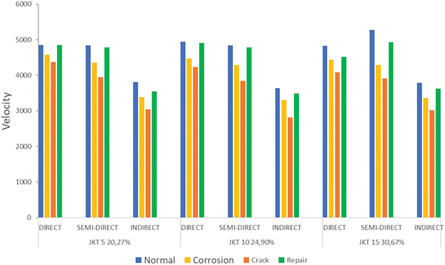
Figure 18: Differences in velocity values in structures before and after repair with jacketing method
3.4.6 Comparison of Repair Grouting and Jacketing Waveforms
Differences in the UPV waveform between repair grouting and jacketing can occur due to variations in the repair methods and the structural characteristics produced by these processes. However, both methods can enhance UPV velocity values but may not reach the same level as normal concrete. Figs. 19 and 20 illustrate the differences in waveform after repair. Based on these results, it can be concluded that concrete with jacketing repair exhibits a higher signal shape compared to grouting repair. This is because jacketing repair shows more uniform and extensive changes across the entire surface of the reinforced concrete.

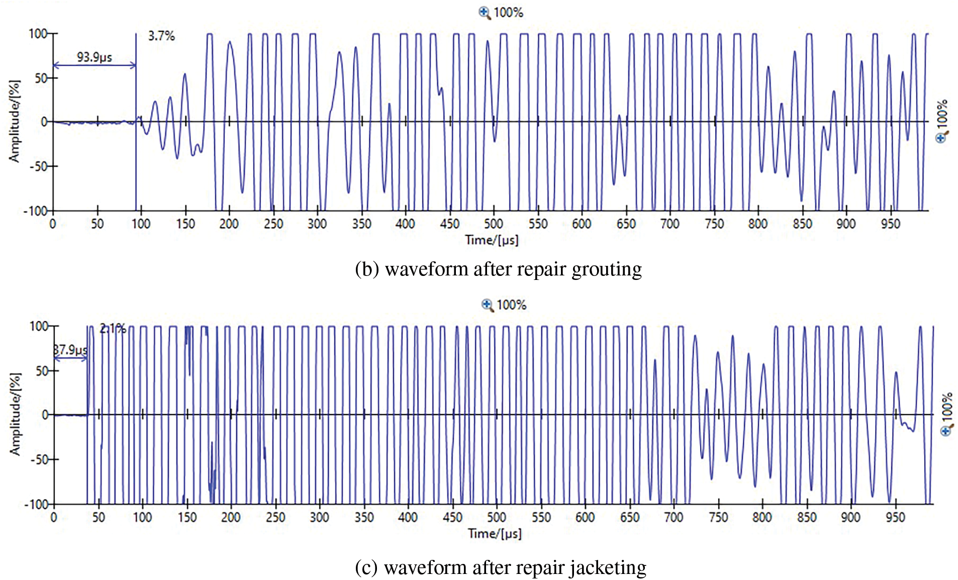
Figure 19: Comparison of signal shapes in grouting and jacketing repairs
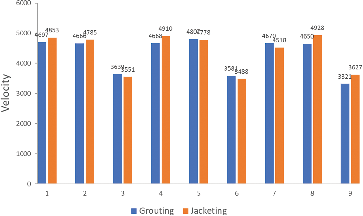
Figure 20: Comparison of velocity repair grouting and jacketing
This research presents the results of a study on the effects of grouting and jacketing repairs on concrete damaged by steel reinforcement corrosion using the Ultrasonic Pulse Velocity (UPV) of the NDT method. Acceleration of corrosion in concrete reinforcement is carried out using the galvanostatic method, and time estimation is done using Faraday’s Law. Concrete that has experienced accelerated corrosion is then loaded in two phases: first, to get initial cracks in the concrete, and second, for grouting and jacketing repairs. After repair, a bending test is carried out to the maximum limit to assess the effectiveness of the repair method.
UPV testing is divided into four stages: normal conditions, after accelerated corrosion, after loading, and after repair. UPV uses two probes, a transmitter, and a receiver, which are attached to each side of the concrete. The grouting repair method is carried out by injecting grout material into cracks caused by corrosion and loading, while jacketing is carried out by adding a new layer that covers the entire part of the concrete.
Actual corrosion calculations show differences with estimates based on Faraday’s Law, which is thought to be caused by the concrete surface being in contact with Styrofoam so that the NaCl solution cannot wet the surface. In addition, the mass calculated based on Faraday’s Law is assumed to be general corrosion, even though, in reality, there is local corrosion. The UPV test results show that the greater the percentage of corrosion, the lower the velocity value. The repair process with grouting and jacketing increases the velocity value and improves the wave shape. Comparison between grouting and jacketing methods shows that jacketing has a higher velocity value and a more uniform wave shape than grouting. The flexural test results also show that concrete using the jacketing method has higher strength than grouting because the repair is more thorough with the addition of an additional layer of solidity. In conclusion, the use of UPV as a monitoring tool was successfully implemented, and the jacketing repair method was proven to be superior to grouting in increasing the strength and stability of corroded concrete.
Acknowledgement: None.
Funding Statement: This work was supported by the Ministry of Education, Culture, Research, and Technology (Indonesia), Grant number 107/E5/PG.02.00.PL/2024, AZ.
Author Contributions: The authors confirm their contribution to the paper as follows: study conception and design: Ahmad Zaki; data collection: Rivky Afanda; analysis and interpretation of results: Ahmad Zaki, Rivky Afanda; draft manuscript preparation: Rivky Afanda. All authors reviewed the results and approved the final version of the manuscript.
Availability of Data and Materials: The data of this study are available from the corresponding author, upon reasonable request.
Ethics Approval: Not applicable.
Conflicts of Interest: The authors declare no conflicts of interest to report regarding the present study.
References
1. Du P, Xu D, Huang S, Cheng X. Assessment of corrosion of reinforcing steel bars in concrete using embedded piezoelectric transducers based on ultrasonic wave. Const Build Mat. 2017;151:925–30. doi:10.1016/j.conbuildmat.2017.06.153. [Google Scholar] [CrossRef]
2. Sharma N, Sharma S, Sharma SK, Mehta R. Evaluation of corrosion inhibition and self healing capabilities of nanoclay and tung oil microencapsulated epoxy coatings on rebars in concrete. Constr Build Mater. 2020;259:120278. doi:10.1016/j.conbuildmat.2020.120278. [Google Scholar] [CrossRef]
3. Zaki A, Rahayu H, Nugraha DA, Rosyidi SAP, Kencanawati NN, Fonna S editors. Resistivity method evaluation of corroded OPS-concrete. E3S Web Conf. 2024;476:01037. doi:10.1051/e3sconf/202447601037. [Google Scholar] [CrossRef]
4. Damtoft JS, Lukasik J, Herfort D, Sorrentino D, Gartner EM. Sustainable development and climate change initiatives. Cement Concrete Res. 2008;38(2):115–27. doi:10.1016/j.cemconres.2007.09.008. [Google Scholar] [CrossRef]
5. Nindhita KW, Zaki A, Zeyad AM. Effect of bacillus subtilis bacteria on the mechanical properties of corroded self-healing concrete. Frattura ed Integrità Strutturale. 2024;18(68):140–58. doi:10.3221/IGF-ESIS.68.09. [Google Scholar] [CrossRef]
6. Zaki A, Jusman Y, Johari M, Hussin W. Image processing for corrosion quantification in concrete slabs using GPR data. J Phys: Conf Ser. 2020;1471:012049. doi:10.1088/1742-6596/1471/1/012049. [Google Scholar] [CrossRef]
7. Rodrigues R, Gaboreau S, Gance J, Ignatiadis I, Betelu S. Reinforced concrete structures: a review of corrosion mechanisms and advances in electrical methods for corrosion monitoring. Constr Build Mater. 2021;269:121240. doi:10.1016/j.conbuildmat.2020.121240. [Google Scholar] [CrossRef]
8. Maddumahewa K, Madusanka N, Piyathilake S, Sivahar V. Ultrasonic nondestructive evaluation of corrosion damage in concrete reinforcement bars. In: 2017 Moratuwa Engineering Research Conference (MERCon), 2017; Moratuwa, Sri Lanka: IEEE. [Google Scholar]
9. Asaad MA, Ismail M, Tahir MM, Huseien GF, Raja PB, Asmara YP. Enhanced corrosion resistance of reinforced concrete: role of emerging eco-friendly Elaeis guineensis/silver nanoparticles inhibitor. Const Build Mat. 2018;188:555–68. doi:10.1016/j.conbuildmat.2018.08.140. [Google Scholar] [CrossRef]
10. Wang Y, Fang G, Ding W, Han N, Xing F, Dong B. Self-immunity microcapsules for corrosion protection of steel bar in reinforced concrete. Sci Rep. 2015;5(1):18484. doi:10.1038/srep18484. [Google Scholar] [PubMed] [CrossRef]
11. Green W. Steel reinforcement corrosion in concrete-an overview of some fundamentals. Corros Eng Sci Technol. 2020;55(4):289–302. doi:10.1080/1478422X.2020.1746039. [Google Scholar] [CrossRef]
12. Stewart MG, Bastidas-Arteaga E. Corrosion of concrete and steel structures in a changing climate. In: Climate adaptation engineering. UK: Elsevier; 2019. p. 99–125. [Google Scholar]
13. Aslani F, Dehestani M. Probabilistic impacts of corrosion on structural failure and performance limits of reinforced concrete beams. Constr Build Mater. 2020;265:120316. doi:10.1016/j.conbuildmat.2020.120316. [Google Scholar] [CrossRef]
14. Zaki A, Rosyidi SAP, Kencanawati NN, Fonna S, Ibrahim Z, Khalid HR, et al. Evaluation of corroded OPS fiber-concrete using NDT method. Int J Integ Eng. 2024;16(1):361–77. [Google Scholar]
15. Ahmadi J, Feirahi MH, Farahmand-Tabar S, Fard AHK. A novel approach for non-destructive EMI-based corrosion monitoring of concrete-embedded reinforcements using multi-orientation piezoelectric sensors. Constr Build Mater. 2021;273:121689. doi:10.1016/j.conbuildmat.2020.121689. [Google Scholar] [CrossRef]
16. Li B, Wang F, Fang H, Yang K, Zhang X, Ji Y. Experimental and numerical study on polymer grouting pretreatment technology in void and corroded concrete pipes. Tunnelling Undergr Space Technol. 2021;113:103842. doi:10.1016/j.tust.2021.103842. [Google Scholar] [CrossRef]
17. Zaki A. GPR assessment method of reinforced concrete structures: a review. In: Proceedings of AWAM International Conference on Civil Engineering 2022, 2022; vol. 2, p. 547–61. doi:10.1007/978-981-99-6018-7_40. [Google Scholar] [CrossRef]
18. Li X, Xiao S, Gao R, Harries KA, Wang Z, Xu Q. Effects of grout sleeve defects and their repair on the seismic performance of precast concrete frame structures. Eng Struct. 2021;242:112619. doi:10.1016/j.engstruct.2021.112619. [Google Scholar] [CrossRef]
19. Raza S, Khan MK, Menegon SJ, Tsang H-H, Wilson JL. Strengthening and repair of reinforced concrete columns by jacketing: state-of-the-art review. Sustainability. 2019;11(11):3208. doi:10.3390/su11113208. [Google Scholar] [CrossRef]
20. Xue J, Lavorato D, Bergami AV, Nuti C, Briseghella B, Marano GC, et al. Severely damaged reinforced concrete circular columns repaired by turned steel rebar and high-performance concrete jacketing with steel or polymer fibers. Appl Sci. 2018;8(9):1671. doi:10.3390/app8091671. [Google Scholar] [CrossRef]
21. Zhao Y, Zou R, Ding T, Xiao J. Experimental study of the shear behaviour of concrete-grout-concrete joints. J Build Eng. 2021;43:103095. doi:10.1016/j.jobe.2021.103095. [Google Scholar] [CrossRef]
22. Lefever G, Van Hemelrijck D, Aggelis DG, Snoeck D. Evaluation of self-healing in cementitious materials with superabsorbent polymers through ultrasonic mapping. Constr Build Mater. 2022;344:128272. doi:10.1016/j.conbuildmat.2022.128272. [Google Scholar] [CrossRef]
23. Zaki A, Chai HK, Aggelis DG, Alver N. Non-destructive evaluation for corrosion monitoring in concrete: a review and capability of acoustic emission technique. Sensors. 2015;15(8):19069–101. doi:10.3390/s150819069. [Google Scholar] [PubMed] [CrossRef]
24. Liu S, Bundur ZB, Zhu J, Ferron RD. Evaluation of self-healing of internal cracks in biomimetic mortar using coda wave interferometry. Cem Concr Res. 2016;83:70–8. doi:10.1016/j.cemconres.2016.01.006. [Google Scholar] [CrossRef]
25. Bolborea B, Baera C, Dan S, Gruin A, Burduhos-Nergis D-D, Vasile V. Concrete compressive strength by means of ultrasonic pulse velocity and moduli of elasticity. Materials. 2021;14(22):7018. doi:10.3390/ma14227018. [Google Scholar] [PubMed] [CrossRef]
26. Rahita AC, Zaki A editors. Corrosion analysis on reinforcing steel in concrete using the eddy current method. In: 2023 3rd International Conference on Electronic and Electrical Engineering and Intelligent System (ICE3IS), 2023; Yogyakarta, Indonesia: IEEE. [Google Scholar]
27. Kim H, Liu X, Ahn E, Shin M, Shin SW, Sim S-H. Performance assessment method for crack repair in concrete using PZT-based electromechanical impedance technique. NDTE Int. 2019;104(9):90–7. doi:10.1016/j.ndteint.2019.04.004. [Google Scholar] [CrossRef]
28. Zaki A, Sunaryo DNY, Afanda R editors. Corrosion analysis on reinforced concrete using ultrasonic pulse velocity. In: 2023 International Workshop on Artificial Intelligence and Image Processing (IWAIIP), 2023; Yogyakarta, Indonesia: IEEE. [Google Scholar]
29. In C-W, Holland RB, Kim J-Y, Kurtis KE, Kahn LF, Jacobs LJ. Monitoring and evaluation of self-healing in concrete using diffuse ultrasound. NDTE Int. 2013;57(5):36–44. doi:10.1016/j.ndteint.2013.03.005. [Google Scholar] [CrossRef]
30. Camara LA, Wons M, Esteves IC, Medeiros-Junior RA. Monitoring the self-healing of concrete from the ultrasonic pulse velocity. J Composit Sci. 2019;3(1):16. doi:10.3390/jcs3010016. [Google Scholar] [CrossRef]
31. Xu N, Song Z, Guo M-Z, Jiang L, Chu H, Pei C, et al. Employing ultrasonic wave as a novel trigger of microcapsule self-healing cementitious materials. Cem Concr Compos. 2021;118(6):103951. doi:10.1016/j.cemconcomp.2021.103951. [Google Scholar] [CrossRef]
32. Nasional B.S. SNI. SNI 03-4142-1996. Metode Pengujian Jumlah Bahan dalam Agregat yang Lolos Saringan Nomor 200 (00075 mm); 1996. Available from: http://sispk.bsn.go.id/SNI/DetailSNI/4554. [Accessed 2024]. [Google Scholar]
33. Dixon DE, Prestrera JR, Burg G, Chairman S, Abdun-Nur E, Barton S, et al. Standard practice for selecting proportions for normal. Heavyweight, and Mass Concrete (ACI 2111-91); 1991. Available from: https://www.concrete.org/store/productdetail.aspx?ItemID=211191&Format=DOWNLOAD&Language=English&Units=US_Units. [Accessed 2024]. [Google Scholar]
34. Zaki A, Megat Johari MA, Wan Hussin WMA, Jusman Y. Experimental assessment of rebar corrosion in concrete slab using ground penetrating radar (GPR). Int J Corros. 2018;2018(283):1–10. doi:10.1155/2018/5389829. [Google Scholar] [CrossRef]
35. Considine TA. States UARLAPGU. Standard Operating Procedure for Accelerated Corrosion Testing at ARL: US Army Research Laboratory; 2017. Available from: https://apps.dtic.mil/sti/pdfs/AD1041960.pdf. [Accessed 2024]. [Google Scholar]
36. Testing ASf, Materials. ASTM G31-72: standard practice for laboratory immersion corrosion testing of metals; 2004. Available from: https://www.astm.org/g0031-72r04.html. [Accessed 2024]. [Google Scholar]
37. Zaki A, Ibrahim Z. Corrosion assessment of pre-corrosion concrete specimens using acoustic emission technique. J Eng Technol Sci. 2021;53(2):210111. doi:10.5614/j.eng.technol.sci.2021.53.2.11. [Google Scholar] [CrossRef]
38. Indonesia BSN. Cara uji kuat lentur beton normal dengan dua titik pembebanan. SNI 4431: 2011. Available from: http://sispk.bsn.go.id/SNI/DetailSNI/8917. [Google Scholar]
39. Climent MÁ, Miró M, Carbajo J, Poveda P, de Vera G, Ramis J. Use of non-linear ultrasonic techniques to detect cracks due to steel corrosion in reinforced concrete structures. Materials. 2019;12(5):813. doi:10.3390/ma12050813. [Google Scholar] [PubMed] [CrossRef]
40. Snoeck D, Malm F, Cnudde V, Grosse CU, Van Tittelboom K. Validation of self-healing properties of construction materials through nondestructive and minimal invasive testing. Adv Mater Interfaces. 2018;5(17):1800179. doi:10.1002/admi.201800179. [Google Scholar] [CrossRef]
41. Nanayakkara O, Najm HM, Sabri MMS. Effect of using steel bar reinforcement on concrete quality by ultrasonic pulse velocity measurements. Materials. 2022;15(13):4565. doi:10.3390/ma15134565. [Google Scholar] [PubMed] [CrossRef]
42. Ndagi A, Umar A, Hejazi F, Jaafar M. Non-destructive assessment of concrete deterioration by ultrasonic pulse velocity: a review. IOP Conf Ser: Earth Environ Sci. 2019;357:012015. doi:10.1088/1755-1315/357/1/012015. [Google Scholar] [CrossRef]
43. Hannachi S, Guetteche M editors. Review of the ultrasonic pulse velocity evaluating concrete compressive strength on site. In: Proceedings of Scientific Cooperation International Workshops on Engineering Branches, 2014; Istanbul, Turkey: Koc University. [Google Scholar]
44. Malhotra VM, Carino NJ. Handbook on nondestructive testing of concrete. Boca Raton: CRC Press; 2003. [Google Scholar]
45. Hong R. Damage detection in fiber reinforced concrete with ultrasonic pulse velocity testing (M.S. Thesis). University of Maryland: USA; 2012. [Google Scholar]
46. Archibong G, Sunday E, Akudike J, Okeke O, Amadi C. A review of the principles and methods of soil stabilization. Int J Adv Acad Res. 2020;6(3):2488–9849. [Google Scholar]
47. Silva DA JRMC. Use of cement based grouts in the rehabilitation of concrete dams: a review; 2019. Available from: https://www.ndt.net/article/smar2019/papers/We.2.B.8.pdf. [Accessed 2024]. [Google Scholar]
48. Doshi S, Patel D, Patel KB, Patel KB, Mavani P. Methodology for prevention and repair of cracks in building. GRD J-Glob Res Develop J Eng. 2018;3(3):52–7. [Google Scholar]
49. Marinescu M, Brouwers H. Free and bound chloride contents in cementitious materials. In: 8th fib International PhD Symposium in Civil Engineering, 2010; Lyngby, Denmark. [Google Scholar]
50. Nguyen CV, Lambert P. Effect of current density on accelerated corrosion of reinforcing steel bars in concrete. Struct Infrastruct Eng. 2018;14(11):1535–46. doi:10.1080/15732479.2018.1459745. [Google Scholar] [CrossRef]
51. Xia J, Jin W-L, Li L-Y. Effect of chloride-induced reinforcing steel corrosion on the flexural strength of reinforced concrete beams. Magaz Concrete Res. 2012;64(6):471–85. doi:10.1680/macr.10.00169. [Google Scholar] [CrossRef]
52. Bicer K, Yalciner H, Balkıs AP, Kumbasaroglu A. Effect of corrosion on flexural strength of reinforced concrete beams with polypropylene fibers. Const Build Mat. 2018;185(2):574–88. doi:10.1016/j.conbuildmat.2018.07.021. [Google Scholar] [CrossRef]
53. Almashakbeh Y, Saleh E. Evaluation of ultrasonic pulse velocity (UPV) for reinforced concrete corrosion. J Appl Eng Sci. 2022;20(4):1226–33. doi:10.5937/jaes0-38140. [Google Scholar] [CrossRef]
54. Watanabe T, Trang HTH, Harada K, Hashimoto C. Evaluation of corrosion-induced crack and rebar corrosion by ultrasonic testing. Const Build Mat. 2014;67(12):197–201. doi:10.1016/j.conbuildmat.2014.05.013. [Google Scholar] [CrossRef]
Cite This Article
 Copyright © 2025 The Author(s). Published by Tech Science Press.
This work is licensed under a Creative Commons Attribution 4.0 International License , which permits unrestricted use, distribution, and reproduction in any medium, provided the original work is properly cited.
 Downloads
 Citation Tools