 Open Access
ARTICLE
Dynamic Interaction Analysis of Coupled Axial-Torsional-Lateral Mechanical Vibrations in Rotary Drilling Systems
1 Applied Automation Laboratory, Faculty of Hydrocarbons and Chemistry, University of Boumerdes, Boumerdes, 35000, Algeria
2 Institute of Electrical and Electronic Engineering (IGEE), University of Boumerdes, Boumerdes, 35000, Algeria
3 Laboratory of the Electrification of Industrial Enterprises, University of Boumerdes, Boumerdes, 35000, Algeria
4 Electrical Engineering Department, Mohamed Boudiaf University of M’sila, M’sila, 28000, Algeria
5 Department of Civil and Environmental Engineering, King Fahd University of Petroleum & Minerals, Dhahran, 31261, Saudi Arabia
6 Interdisciplinary Research Center for Construction and Building Materials, King Fahd University of Petroleum & Minerals (KFUPM), Dhahran, 31261, Saudi Arabia
* Corresponding Authors: Sabrina Meddah. Email: ; Kong Fah Tee. Email:
,
Structural Durability & Health Monitoring 2025, 19(1), 77-103. https://doi.org/10.32604/sdhm.2024.053541
Received 03 May 2024; Accepted 13 August 2024; Issue published 15 November 2024
Abstract
Maintaining the integrity and longevity of structures is essential in many industries, such as aerospace, nuclear, and petroleum. To achieve the cost-effectiveness of large-scale systems in petroleum drilling, a strong emphasis on structural durability and monitoring is required. This study focuses on the mechanical vibrations that occur in rotary drilling systems, which have a substantial impact on the structural integrity of drilling equipment. The study specifically investigates axial, torsional, and lateral vibrations, which might lead to negative consequences such as bit-bounce, chaotic whirling, and high-frequency stick-slip. These events not only hinder the efficiency of drilling but also lead to exhaustion and harm to the system’s components since they are difficult to be detected and controlled in real time. The study investigates the dynamic interactions of these vibrations, specifically in their high-frequency modes, using field data obtained from measurement while drilling. The findings have demonstrated the effect of strong coupling between the high-frequency modes of these vibrations on drilling system performance. The obtained results highlight the importance of considering the interconnected impacts of these vibrations when designing and implementing robust control systems. Therefore, integrating these components can increase the durability of drill bits and drill strings, as well as improve the ability to monitor and detect damage. Moreover, by exploiting these findings, the assessment of structural resilience in rotary drilling systems can be enhanced. Furthermore, the study demonstrates the capacity of structural health monitoring to improve the quality, dependability, and efficiency of rotary drilling systems in the petroleum industry.Keywords
Nomenclature
| | Mass moment of inertia terms |
| | Damping terms |
| | External excitation forces applied to the system |
| | Axial displacement, velocity and acceleration |
| | Torsional displacement, velocity and acceleration |
| | Lateral displacement, velocity and acceleration |
| | Rock-bit interaction force on the axial dynamic |
In the petroleum industry, one of the most important systems that plays a crucial role in exploration and production activities is the rotary drilling system. This system is specifically designed to effectively drill boreholes and extract lucrative oil and gas from targeted reservoirs in the subsurface. To penetrate the geological layers and dig boreholes toward the oil and gas reservoirs, the rotary drilling technology connects a spinning drill bit to a drill string, as shown in Fig. 1a. Such equipment facilitates the exploration of deep reservoirs that contain profitable energy resources. Therefore, its durability and health monitoring may have a significant impact on the success of petroleum exploration and production operations. However, various types of unwanted mechanical vibrations can have a substantial impact on drilling performance in this structural system. The axial, torsional, and lateral vibrations are generally stimulated by the interaction between the drill string or drill bit and the rocks. Bit bounce, which is the most severe case of axial vibrations, has the ability to cause damage to drilling equipment, while severe torsional vibrations lead to stick-slip phenomena, which create difficulties in maintaining a uniform drilling speed and generate drill bit damage and fatigue. The lateral vibrations increase the unpredictable spinning problems and borehole geometry irregularities [1]. Furthermore, the complex interaction dynamics of the three strongly coupled vibrations make this system’s monitoring more complex [2]. Hence, investigating and analyzing these interactions is vital for designing efficient control techniques to mitigate these vibrations and prevent the structural durability of rotary drilling system equipment.
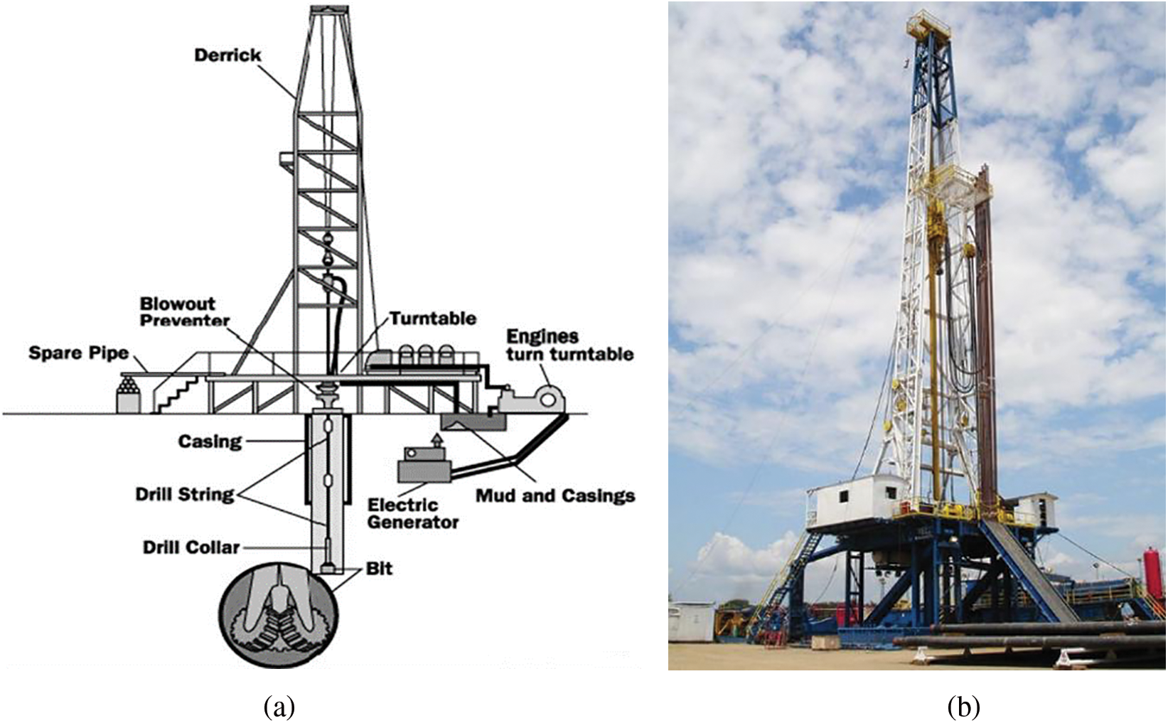
Figure 1: The rotary drilling system: (a) detAILED schematic diagram of the system, (b) example of an operational system in the field
Over the last few decades, significant progress has been made in the field of rotary drilling systems. Many researchers have been investigating the interaction between axial, torsional, and lateral vibrations, as well as their effects on the efficiency of drilling operations and equipment durability. In 2019, de Luciano Marcelo analyzed the effect of coupled axial-torsional-lateral nonsmooth vibrations on the drill string of a rotary drilling system [2]. Subsequent investigations have examined the interconnected nature of these vibrations, highlighting the necessity of employing a multi-body dynamics approach and stochastic analysis. Researchers have made significant contributions to this topic through a variety of methods [3]. Several researchers have performed stochastic analysis on the lateral-torsional vibrations of drill strings, underlining the significance of understanding the interconnected dynamics. Fushen et al. in [4] looked into strongly coupled vibrations by proposing nonlinear models and checking the rotary drilling system’s quality of integrity.
The research on this topic has been extensive, with scholars building upon each other’s work to get a more profound understanding of these vibrations and their interaction dynamics. Fallahi in [3], Jingkai et al. in [5], and Fang et al. in [6] investigated the interaction among axial, lateral, and torsional vibrations. These references carefully discussed the significance of employing a multi-body dynamics methodology and performing stochastic analysis. Later, Volpi et al. in [7] contributed to this research topic by conducting a stochastic analysis of lateral-torsional vibrations in drill strings. Their study focused on the interaction types involved in the system’s dynamics. Additional researchers, such as Khulief et al. in [8], Shujie et al. in [9], and Fushen et al. in [4], have also examined coupled vibrations. They have constructed nonlinear models and conducted qualitative analyses. Then, Guo et al. in [10] expanded their study for ultra-high pressure, high temperature (HPHT) deviated wells, considering the effect of the borehole deviation on the nonlinear interaction between axial, lateral, and torsional forces.
In more recent research works, Jun et al. in [11], Yu et al. in [12], and Yong-Min et al. in [13] have extended the investigation to cover the impact of seawater and rock layers, non-smooth features, and mode correlation analysis. Previously, Guo et al. in [14] and Khulief et al. in [15] studied self-excited stick-slip oscillations and their vibration analysis, offering useful knowledge on controlling drilling vibrations, but only for torsional vibration, neglecting the coupling effects. Thus, Tian et al. in [16] looked into how directional drilling interacts with a drill string rotary controller, and Saldivar et al. in [17] provided a full analysis and control framework for vibrations in oilwell drilling. Youyu et al. in [18] conducted research to examine the effects of vibrations on mine support systems. Similar to Yong-Min et al., their study investigated the impact of torsional stick-slip vibrations on the whirl behavior of drill string systems [1]. Al Dushaishi et al. examined dominant models in the study of drill stem vibrations [19], enhancing our understanding of vibration interaction dynamics. For control design purposes, Tian et al. proposed a sliding mode-PI controller in [20] to examine the vibration characteristics of a drill string. The studies listed above give a thorough look at the complicated behavior of axial, torsional, and lateral vibrations in rotary drilling systems, focusing on low-frequency modes. For high-frequency modes, Riane et al. in [21] developed a controller that relies on an observer to address torsional vibrations. Even the observer-based controller has demonstrated good performance in mitigating stick-slip vibrations, but it fails in mitigating strongly coupled vibrations because the interaction dynamics were neglected. In a recent study, Meddah et al. in [22] investigated the impact of the strong coupling between axial and torsional vibrations on the performance of a proposed controller. However, the study neglected lateral vibrations. Therefore, the main goal of this manuscript is to look at how the axial, torsional, and lateral vibrations interact in their high-frequency modes using data collected in three oil wells using an MWD tool. The high-frequency mode of these vibrations is crucial because it represents an extreme situation that can cause equipment damage and have a substantial impact on drilling performance, rotary drilling system durability, and drilling equipment lifetime.
The importance of this work is highlighted by the fact that this study examines the high-frequency interactions of axial, torsional, and lateral vibrations in rotary drilling rigs, which are essential for petroleum exploration and extraction. It seeks to analyze the strong coupling of these vibrations based on field data from various oil wells. This method improves the longevity and efficiency of drilling equipment, resulting in a more economically productive process for extracting petroleum. The rest of the manuscript is structured as follows: The second section provides a comprehensive description of the rotary drilling system, including an in-depth analysis of the three types of vibrations and their distinct coupling patterns. The third section focuses on the mathematical model of the rotary drilling system, specifically the interconnected terms between the three types of vibrations. The fourth section is dedicated to the field data measurement analyses obtained from Well-1 and the coupling dynamics. Section five includes two further case studies from Well-2 and Well-3. These case studies present the measurement data produced using the same MWD tool in the same petroleum field. The data shows a considerable coupling impact between the axial, torsional, and lateral vibrations in their high-frequency modes. The manuscript ends with concluding observations and suggestions for future research.
2 Rotary Drilling System Overview
The drilling mechanism depicted in Fig. 1b is of utmost importance for the exploration and production activities in the petroleum industry. This system is designed for the purpose of drilling wells and extracting oil and gas. The system consists of various interconnected components, one of which is a specialized drill bit designed to penetrate rock formations, as demonstrated in Fig. 1a. The drill string, which consists of interconnected pipes, facilitates the circulation of drilling fluid, as well as the transmission of torque and weight to the drill bit [4]. The drilling mud, a fluid used in drilling operations, has many functions, such as cooling and lubricating the drill bit, as well as facilitating the removal of rock’s crushed pieces. The rotary table, derrick, drawworks, and mud pumps are essential components that collaborate in a rotary drilling system. The rotary table governs the rotational movement, the derrick offers support, the draw works manage the hoisting operation, and the mud pumps facilitate the circulation of fluids. Blowout preventers (BOPs) and wellheads are safety mechanisms that prevent uncontrolled releases and ensure the structural stability of the system. The synergy of these diverse components ensures the rotary drilling procedure’s effectiveness, accuracy, and overall security in various conditions in the petroleum drilling field [23].
2.2 Coupled Axial-Torsional-Lateral Vibrations in Drill String
The performance of drilling systems is heavily dependent on vibrations’ dynamic propagation in three directions. Fig. 2 shows the three types of vibrations in rotary drilling systems based on their propagation directions. Axial vibrations, which refer to the vertical movements of the drill pipe, can cause bit bounce and negatively affect the desired rate of penetration (Fig. 2a).
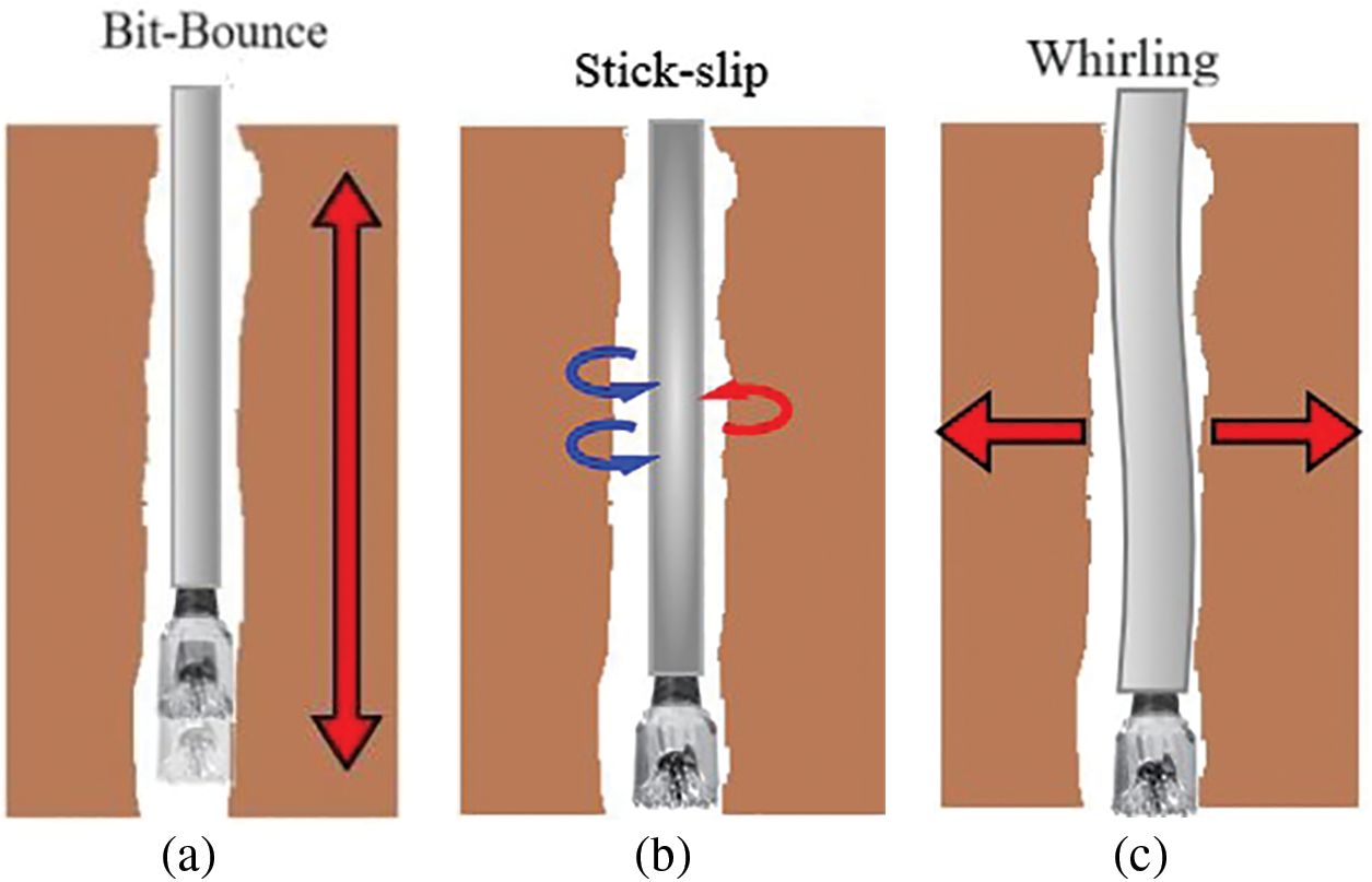
Figure 2: The three vibrations’ modes and their sever cases according to their propagation directions: (a) axial vibration, (b) torsional vibrations, (c) lateral vibrations
Torsional vibrations can lead to stick-slip dynamics that have a detrimental impact on drilling rate stability and drill bit safety (Fig. 2b) [24,25]. Lateral vibrations cause chaotic whirling, which directly influences the borehole geometry (Fig. 2c) [18,19]. These vibrations frequently occur simultaneously during drilling operations, with a strong and complex interaction between them [4]. More precisely, they do not operate autonomously; rather, they have a substantial impact on each other in both directions, but not the same degree of effect [2,8]. Understanding the ever-changing connection between these vibration types is essential for implementing robust controllers to mitigate such vibrations and preserve the drilling equipment’s durability and safety [3,11,26].
Based on previous studies, it has been demonstrated that the stick phase of the torsional vibrations is a stimulator of the other vibrations’ type near the drill bit. Indeed, the cumulated energy during the stuck phase is freed, which creates a chaotic whirling due to the propagation of the energy in the lateral directions. The shocks generated by chaotic whirling then create an axial wave that propagates along the drill string. After a while, a portion of the axial wave is reflected from the contact point, a depth point at which the drill string comes into contact with the geological layer. The reflected axial wave frees the next stick phase to generate the next slip phase, and the cycle is repeated. Fig. 3 shows a diagram that explains this principle in detail.

Figure 3: Dynamic and coupling principle between the torsional, lateral, and vibrations during drilling
From one side, by reducing the weight on the drill bit (WOB), the axial vibrations can be eliminated for one cycle. But, on the other side, to mitigate stick-slip vibration, it is possible to decrease the WOB while simultaneously increasing the speed of the top drive. However, since the chaotic whirling also affects bit bounce, this approach does not resolve the issue. This demonstrates a strong interaction between these vibration types, necessitating further understanding using an appropriate mathematical model as given in Section 3 [3,16].
3 Mathematical Model of Coupled Axial-Torsional-Lateral Vibrations
Analyzing the vibrations in a rotary drilling system is complex since it includes the axial, torsional, and lateral dynamics [12]. Many studies have adopted an alternative model, which is based on analyzing each type of vibration individually and thereafter examining their interactions [4,11]. Such an approach has many limitations; thus, in this study, we consider the equations that describe these vibrations as given in Eq. (1).
The external forces
This study explicitly investigates the interaction terms outlined in Eq. (2) based on real data measured in three wells in a petroleum field using an MWD tool logged during drilling. Fig. 4 shows the detailed flowchart of the steps followed in order to conduct this investigative study. Multiple analytical models exist for these interaction forces; however, our approach analyzes them using field measurements [5]. The data were obtained in a petroleum well with pronounced vibrations, which are also evident in the neighboring wells.
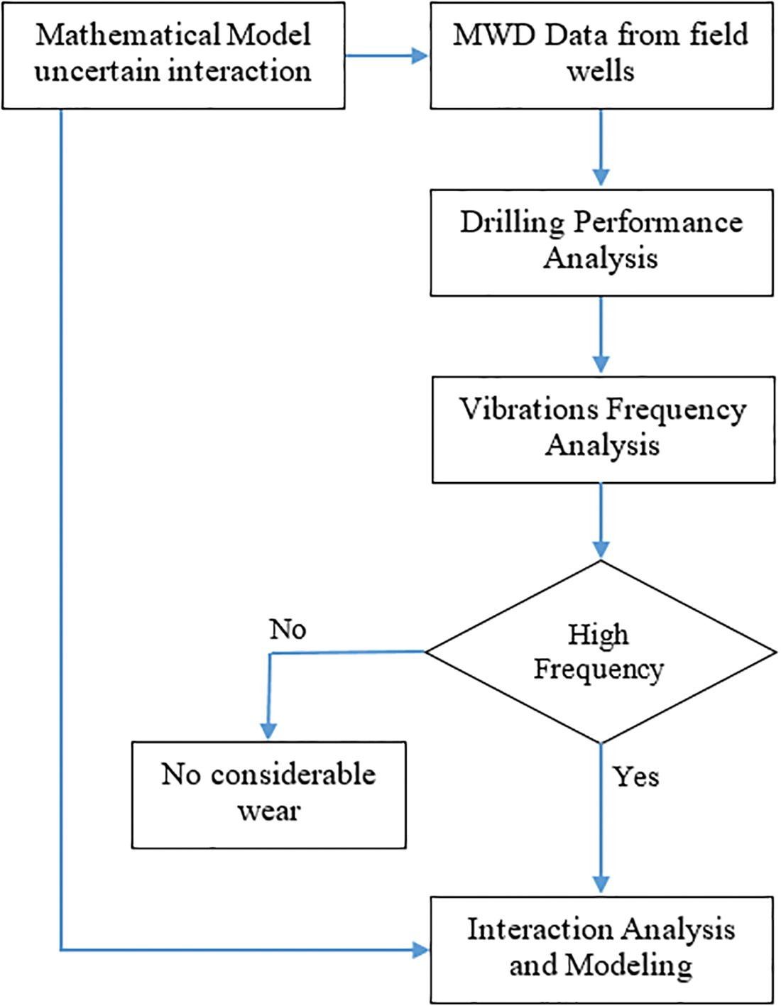
Figure 4: Detailed flowchart of the proposed approach of this study
The well, designated as Well-1, was drilled using a rotary drilling system. The investigation specifically targets the 16-inch section, which was drilled without interruption from a depth of 546 to 2911 m. The cumulative drilling time was 100.62 h, resulting in an average rate of penetration (ROP) of 23.50 m per hour. The well’s trajectory remained perfectly vertical throughout. During the drilling operation, an oil-based mud with a specific gravity of 1.30 was used. The MWD downhole measurement tool was used to collect data at two specific points within the Bottom Hole Assembly (BHA). The initial position was directly above the drill bit, exactly on the NV400 ring stabilizer. The second position was located approximately 19.5 m above the bit, above the third stabilizer. The 16-inch PDC (polycrystalline diamond compact) bit type SI913MBPX [9] was used as the drill bit. This specific bit design features nine blades equipped with 13-mm cutters and an elongated parabolic profile. Despite using a large amount of diamond material to strengthen the shoulder, we have noticed that this design may encounter difficulties when cutting through strong carbonate deposits due to the reduced load per cutter.
An analysis has been conducted on the drilling performance across various geological layers. Table 1 provides a concise overview of these layers and their respective thicknesses.

Fig. 5 demonstrates the quantitative values of WOB and ROP, which reflect the rotary drilling system’s performance at each geological layer of the drilled phase. Based on the information shown in Fig. 5, the ROP is considered to be acceptable in the upper layers, specifically the Barremian formation. Even so, the Aptian formation is different because it has a lower-than-average ROP and higher levels of vibration, which is most likely because it contains dolomitic limestone lithology. After the Barremian formation, there is a decrease in the ROP in the following layers, regardless of the WOB used. Table 1 shows the highest WOB values and corresponding ROPs for each geological layer. The decrease in performance indicates a deterioration in the quality of the bits, possibly caused by dulling or damage. We identify the Aptian formation as the most likely location where this occurred.
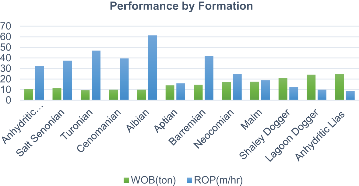
Figure 5: Performance values (WOB and ROP) for different geological layers in Well-1
The used PDC drill bit in this well belongs to the specific category: 3-3-BT-N-X-I-LT/ER-TD. Fig. 6 illustrates the wear and damage to the used PDC drill bit following the drilling phase in Well-1. By analyzing Fig. 6, it becomes apparent that there is significant damage to the bit’s nose cutters. This damage serves as evidence of a flaw in the bit’s design, specifically for this particular use. Although the long parabolic shape is beneficial for keeping a lot of diamond material in the cone and shoulder (both of which stay in beneficial shape), it is also detrimental because it does not place the cutting tools properly. Axial vibration exacerbates the damage to the nose, as the force per cutter is higher in this position compared to other bit sections. One potential solution is to modify the design to fit a medium parabolic shape. Increasing the diamond’s volume would improve nose protection. Particular blades, typically located around the front end, bear the brunt of erosion damage. The exact cause of this fatigue is uncertain. Possible causes include deterioration due to vibration damage, which exposes the steel to high-frequency erosive forces. Otherwise, it could suggest a fundamental problem in the design [5]. A deep examination using vibration frequency and severity analysis is required to confirm or infirm these hypotheses [17].

Figure 6: Images show the wear of the used PDC drill bit in Well-1
The primary objective of logging MWD tool records during drilling operations is to provide a particular frequency analysis of vibration signals. Accurately determining the specific frequencies of vibrations is essential for recognizing where they come from and, as a result, understanding how they interact to implement a robust strategy to mitigate them [21]. The data recorders consistently gather data at a frequency of 2 data points per second (2 Hz), along with additional raw 256 Hz burst data that lasts for 17 s every 20 min. The burst data is a valuable resource for conducting frequency analysis, enabling the observation of vibration signals with frequencies up to 128 Hz, in accordance with the Nyquist theorem. Fig. 7 displays a comprehensive examination of all collected high-frequency lateral vibration burst data at both tool positions [21].
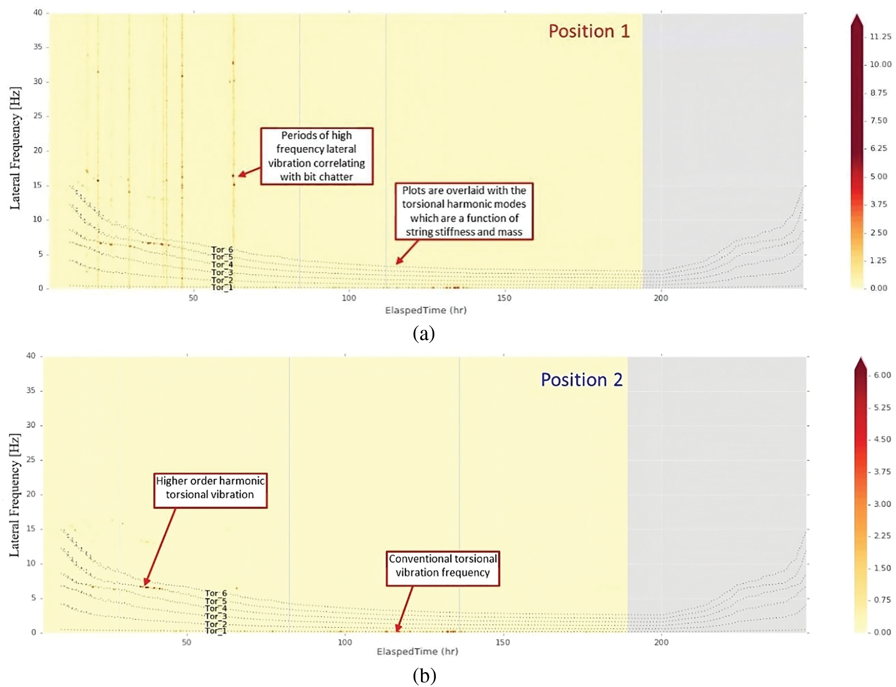
Figure 7: Measured lateral vibration frequencies in well-1 at: (a) Position 1, (b) Position 2
Fig. 7a shows the lateral vibration frequencies as a function of elapsed time at Position 1, which is below the drill bit. While Fig. 7b demonstrates the lateral vibration frequencies at Position 2, The comparison of these two positions’ measurements indicates the axial propagation of these vibrations. This analysis is critical for determining the dominant frequencies and patterns during the drilling operation. Remarkably, there are instances of severe high-frequency lateral vibrations at Position 1 (Fig. 7a), which coincide with the occurrence of fast irregular rotational movements of the drill bit (15 Hz or higher) within the first 60 h of operation. On the other hand, these frequencies exhibit a remarkable decrease in lateral vibrations at the second position (Fig. 7b), indicating a correlation with vibrations connected to the drill bit. Moreover, the graphs are crossed over with modeled harmonic modes for torsional vibration. This makes it possible to find periods with high-frequency torsional vibration, which can be seen at both recording positions.
4.4 Axial, Torsional and Lateral Vibrations
To ensure a successful drilling procedure, it is critical to create the correct pattern for the hole when initially reaching the well bottom. Proper execution of this step is crucial, as any mistakes can cause damage to the PDC cutters. The bit constructor usually supplies the procedure, which necessitates precise monitoring of the WOB and the angular velocity (RPM) in the first 1–2 m of drilling. Although the RPM is appropriately limited in Well-1, the absence of WOB monitoring poses challenges in assessing the precision of the applied weight at this particular step. Consequently, when the cutter engages, the MWD tool sensor package near the drill bit records instances of moderate to high lateral vibration [21]. During the drilling process, the vibration stops at a depth of approximately 0.26 m, which happens when the drill bit reaches the intended bottom hole profile. The difficulty in determining the applied weight may be attributed to the absence of a specifically designated new measured depth (MD) established for the upper limit. This means that the system interprets the bit as being at the lowest point, which prevents the WOB calculation. Prior to the initial bottom tag, it is recommended that the WOB be accurately zeroed and tracked.
To ensure a successful drilling procedure, it is critical to create the correct pattern for the hole when initially reaching the well bottom. Proper execution of this step is crucial, as any mistakes can cause damage to the PDC cutters. The bit constructor usually supplies the procedure, which necessitates precise monitoring of the WOB and the angular velocity (RPM) in the first 1–2 m of drilling. Although the RPM is appropriately limited in Well-1, the absence of WOB monitoring poses challenges in assessing the precision of the applied weight at this particular step. Consequently, when the cutter engages, the MWD tool sensor package near the drill bit records instances of moderate to high lateral vibration [21]. During the drilling process, the vibration stops at a depth of approximately 0.26 m, which happens when the drill bit reaches the intended bottom hole profile. The difficulty in determining the applied weight may be attributed to the absence of a specifically designated new measured depth (MD) established for the upper limit. This means that the system interprets the bit as being at the lowest point, which prevents the calculation of the WOB. Prior to the initial bottom tag, it is recommended to ensure accurate zeroing and tracking of the WOB.
Fig. 8 shows the measured axial, torsional, and lateral vibrations in the Anhydritic Senonian formation at Well-1, along with the ROP and WOB. As depicted in Fig. 8 tracks, the MWD plug, located near the drill bit, records periods of noticeable axial and lateral vibration without any significant changes in parameters. This occurrence frequently coincides with a notable reduction in the ROP, indicating a possible shift in formation. The vibrational intensity decreases significantly at Position 2, located 19.5 m above the drill bit, suggesting that the bit is the source of the vibration. Both positions detect significantly low levels of vibration when the drill bit is not in contact with the surface. Remarkably, there are no visible signs on the surface except for a slow ROP, which indicates intense bit vibration, resulting in a lack of measures to reduce its impact.
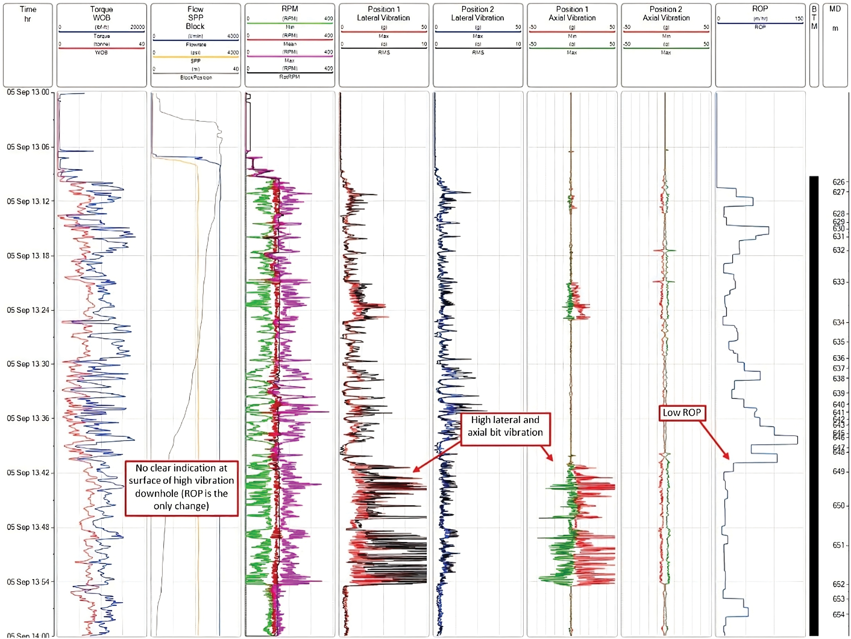
Figure 8: Vibrations measurement at the Anhydritic Senonian formation: Track 1: time, Track 2: torque (blue), WOB (red), Track 3: flow (blue), SPP (yellow), Block (grey), Track 4: RPM min (green), RPM mean (red), RPM max (violet), RPM rms (black), Track 5: Lateral vibrations Position 1 (Max in red, rms in black), Track 6: Lateral vibrations Position 2 (Max in blue, rms in black), Track 7: axial vibrations Position 1 (Max in red, rms in green), Track 8: axial vibrations position 2 (Max in red, rms in green), Track 9: ROP (in blue), Track 10: bottom tool measurement (in black), Track 11: measured depth (MD)
The drill bit vibrations correlate with the changes in the formation, as indicated by the wireline data presented in Fig. 9. This figure shows the correlation between the appearance of severe axial-lateral vibrations and the change in geological formation indicated by the decrease of the Gamma Ray. This implies a shift towards a distinct other type of rock. The Gamma Ray log indicates decreased readings, which often suggests an increase in formation hardness due to a reduction in shale content. Analyzing the mud log reveals that dolomite and dolomitic limestone comprise the rock within this specific depth range. The presence of this more resistant carbonate rock is likely responsible for the measured vibration, as the drill bit encounters difficulties in effectively penetrating it.
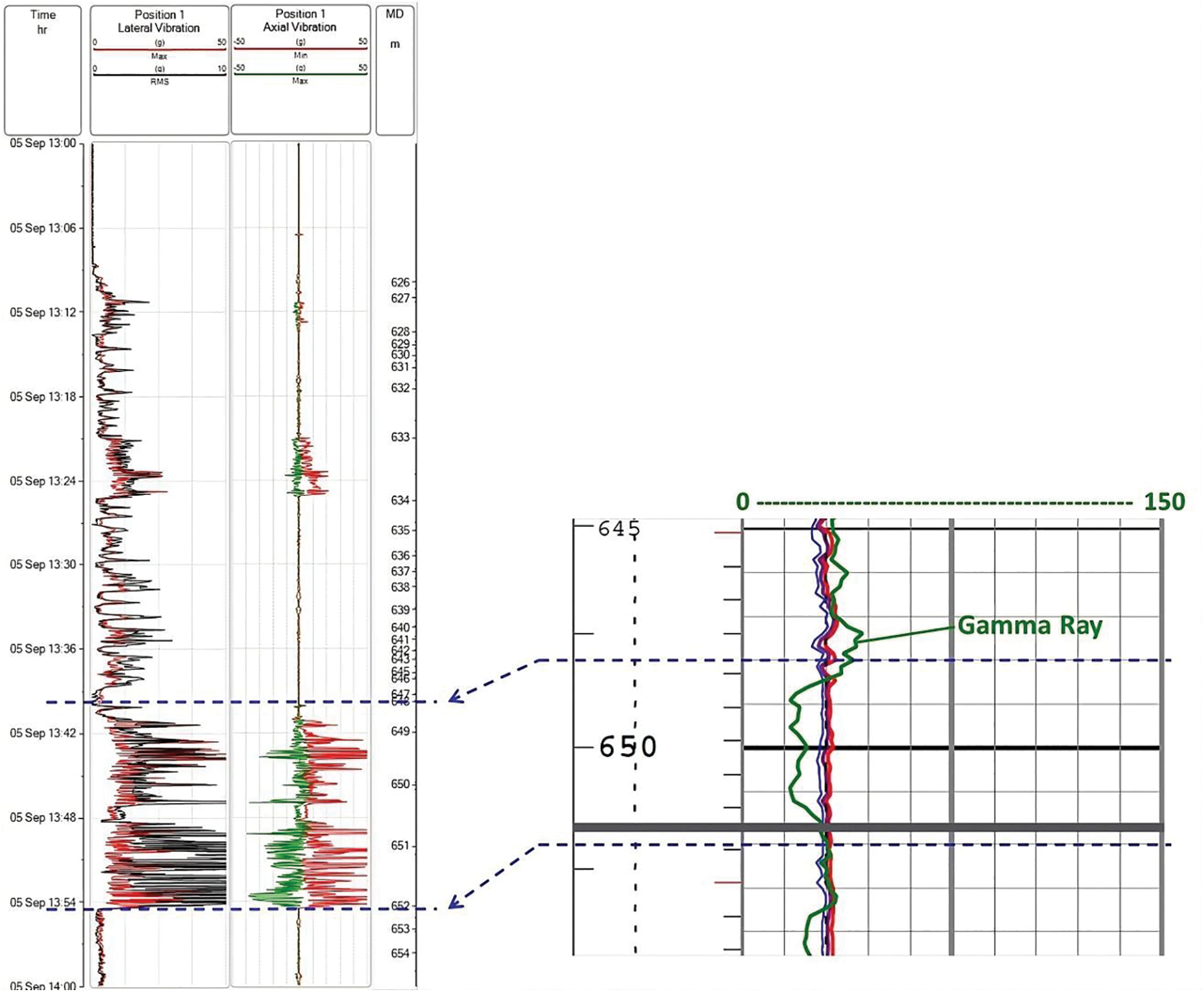
Figure 9: Change of formation influence on lateral and axial vibrations severity
Fig. 10 shows high-frequency burst curves (256 Hz) recorded as a bit vibration event [21]. We have used the Fast Fourier Transform (FFT) method of frequency analysis to identify the main vibration frequencies in both axial and lateral channels. The correspondence of the vibration frequencies in both channels suggests their interconnectedness, where vibrations in one channel exert an influence on the other. By conducting a more detailed analysis of a 100-ms period within the burst data, it is possible to identify the primary vibrations that occur first. The findings reveal that the lateral shocks precede the axial shocks, suggesting that the lateral vibration triggers the axial vibration [7]. The axial shocks exhibit positive values, indicating an upward shock that is worth mentioning. This discovery suggests that the bit undergoes an upward movement after producing a significant sideways impact, which happens at approximately 15 Hz.
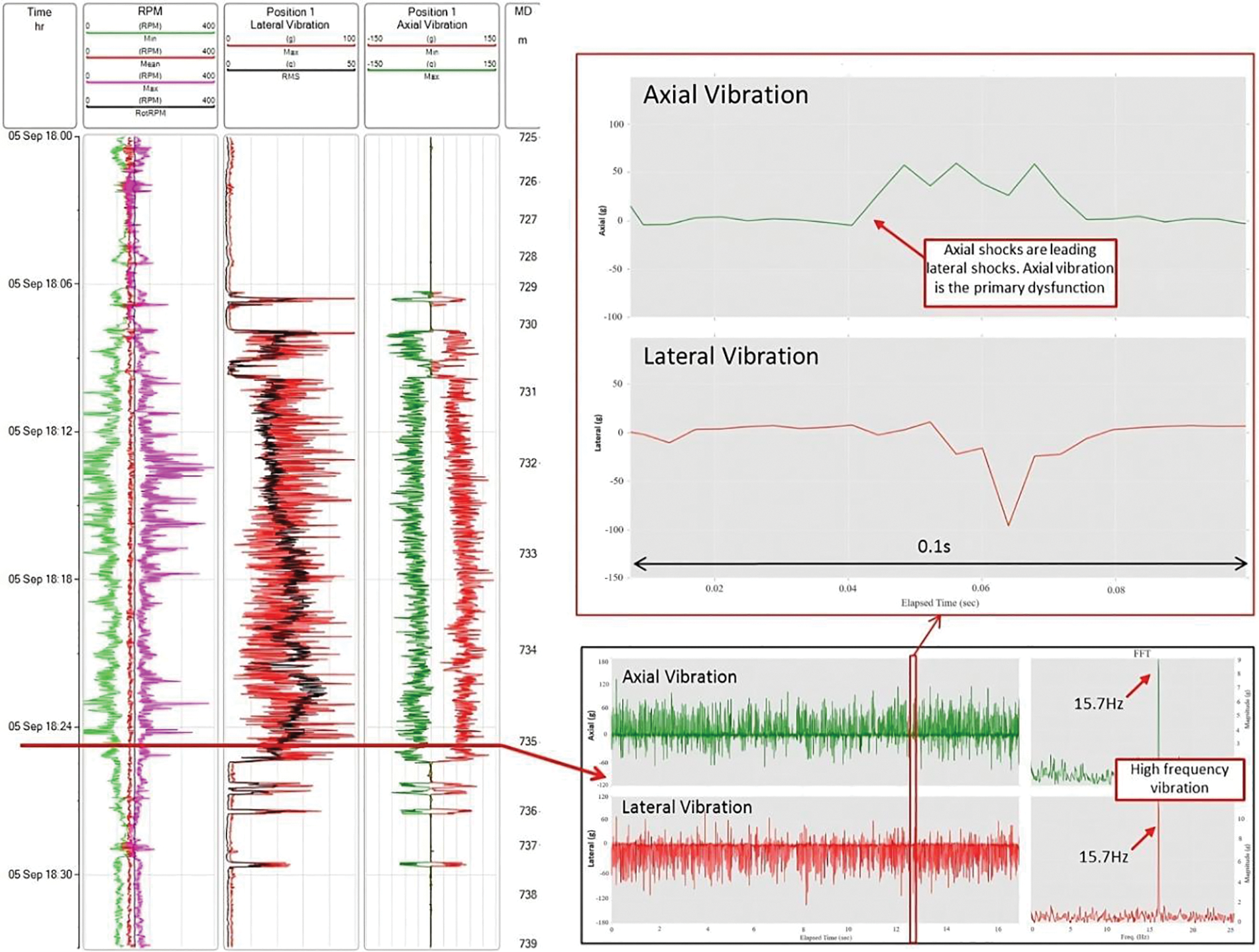
Figure 10: High-frequency axial and lateral vibrations near the drill bit and their FFT: Track 1: time, Track 2: RPM min (green), RPM mean (red), RPM max (violet), RPM rms (black), Track 3: lateral vibrations Position 1 (max in red, rms in black), Track 4: axial vibrations Position 1 (min in red, max in green), Track 5 (lower part): axial vibrations in green, lateral vibration in red, Track 5 (upper part): FFT of axial vibrations in green, FFT of lateral vibration in red
4.5 Low-Frequency vs. High-Frequency Vibrations
The drill bit and the BHA can sometimes generate a reactive torque that surpasses the torque provided from the surface via the drill string. This results in a decrease in the rotational speed (RPM) of the downhole equipment, causing it to become stuck. Eventually, the BHA generates enough torque to rapidly accelerate beyond the surface RPM [9]. The process of sticking and slipping occurs repeatedly, usually in sync with the drill string’s intrinsic torsional frequency, as well as any additional harmonics resulting from the string’s mass and rigidity [10]. The primary natural frequency, which represents the first harmonic mode, is the system’s most frequently occurring torsional. Within this harmonic mode, the variation in RPM (the difference between the highest and lowest RPM values) is most noticeable at the drill bit. Fig. 11 illustrates the various modes of torsional vibrations. This variation steadily decreases as we move towards the surface, ultimately becoming zero at the top drive, as depicted in Fig. 11a. This form of vibration is typically regarded as low-risk, and its intensity can be controlled by making adjustments to the parameters. In contrast, higher-order torsional vibrations, while less common, can cause far greater damage. These measurements demonstrate fourth and fifth mode torsional vibrations, as shown in Fig. 11b. This phenomenon is distinguished by significant changes in rotational speed (RPM) at different locations along the drill string [21].
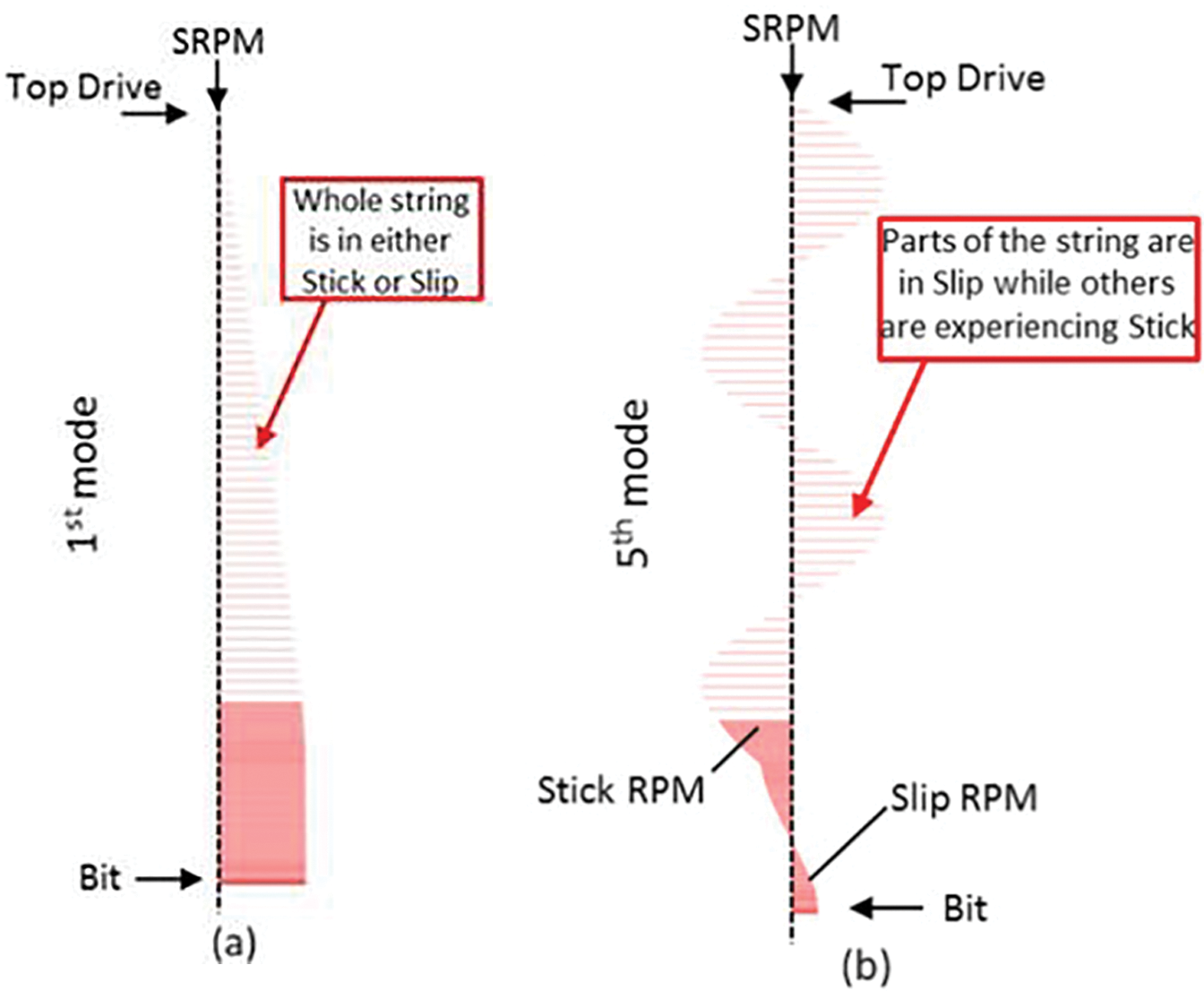
Figure 11: Harmonic modes of torsional vibrations in rotary drilling systems: (a) low-frequency mode, (b) high-frequency mode
Fig. 12 depicts an example of the prevalent low-frequency (1st mode) or classic stick-slip behavior. In this mode, the rate of increase and decrease in rotational speed (RPM) is inherently gradual, and there is not enough force to induce substantial vibrations. Lateral shocks associated with this form of stick-slip are frequently accompanied by increased RPM during the slide phase. This holds true for the provided example, in which the RPM aligns with the most significant sideways vibrations. If increasing the surface’s rotational speed (RPM) does not effectively resolve the stick-slip issue, it is recommended that the RPM setting be decreased [15]. The objective is to restrict the maximum rotational speed in the wellbore during the slip period. The oscillations in surface RPM are associated with variations in torque, which are presumably caused by surpassing the restrictions on the top drive [13]. The variable RPM may be a contributing factor to the stick-slip issue. To resolve this issue, it is advisable to increase the torque limit on the top drive, if feasible, to prevent such incidents from happening. However, such a practice is not effective if we have high-frequency coupled vibrations. Fig. 13 shows the measured dynamics’ high-frequency modes.
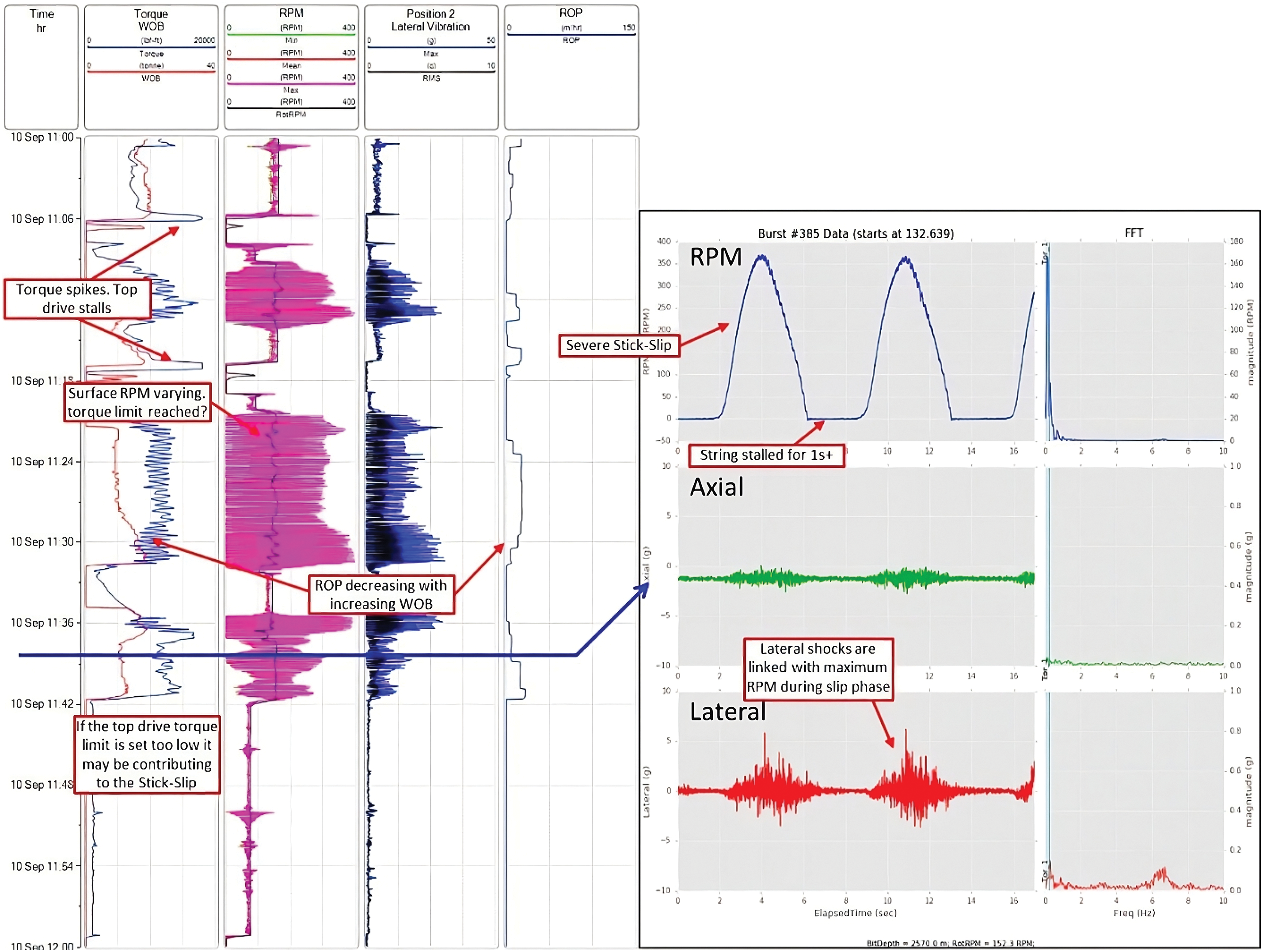
Figure 12: Low-frequency vibration and their fast Fourier transform: Track 1: time (h), Track 2: torque (blue), WOB (red), Track 3: RPM min (green), RPM mean (red), RPM Max (violet), RPM rms (black), Track 4: lateral vibration position (max in blue, rms in black), Track 5: ROP (blue)
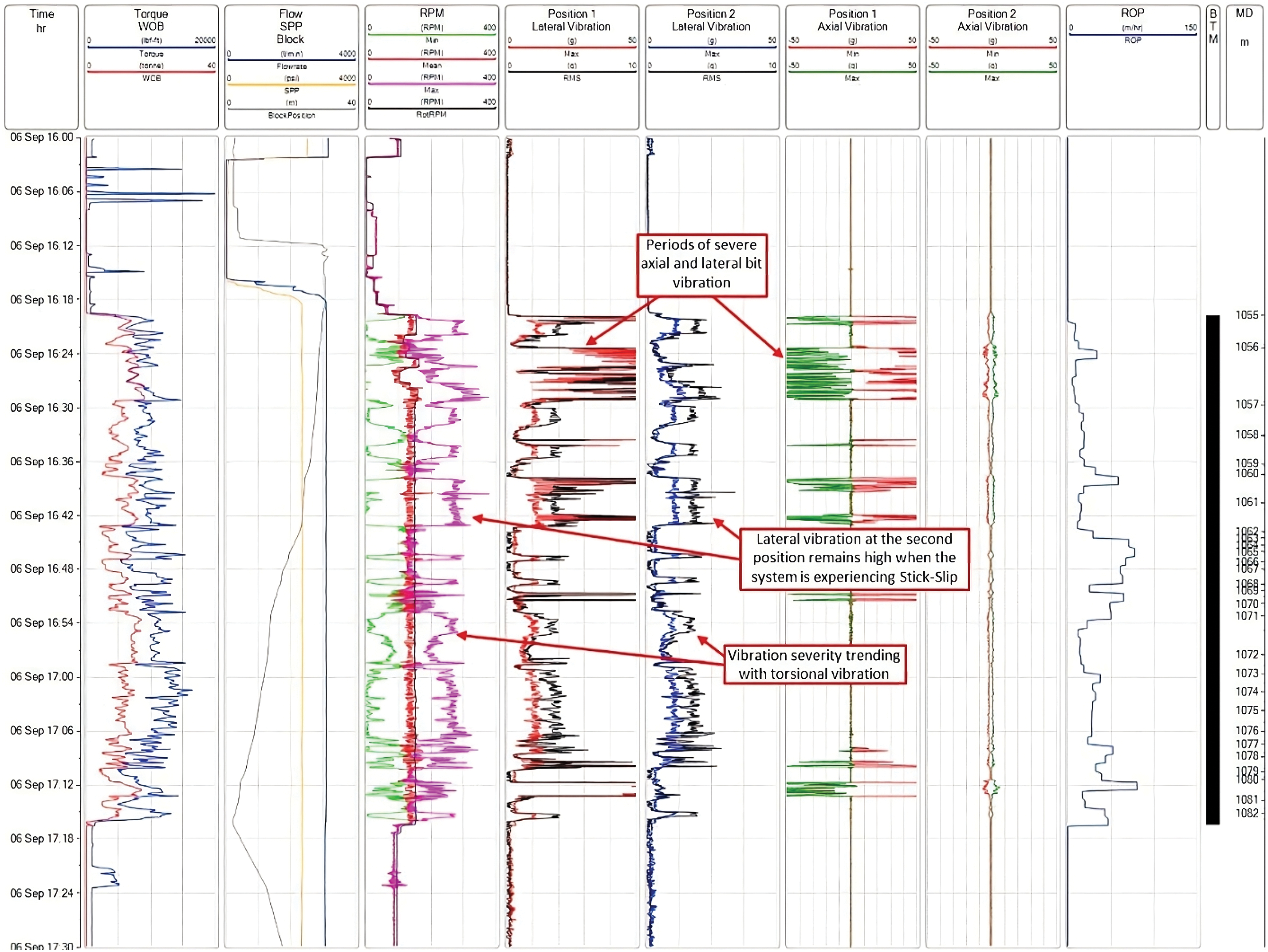
Figure 13: High-frequency vibrations coupling at the Cenomanian formation: Track 1: time, Track 2: torque (blue), WOB (red), Track 3: flow (blue), SPP (yellow), block (grey), Track 4: RPM min (green), RPM mean (red), RPM max (violet), RPM rms (black), Track 5: Lateral vibrations Position 1 (Max in red, rms in black), Track 6: lateral vibrations Position 2 (Max in blue, rms in black), Track 7: axial vibrations Position 1 (Max in red, rms in green), Track 8: axial vibrations Position 2 (Max in red, rms in green), Track 9: ROP (in blue), Track 10: bottom tool measurement (in black), Track 11: measured depth (MD)
The curve presented in Fig. 13 demonstrates a distinct correlation between periods of severe torsional vibrations, characterized by significant fluctuations in angular velocity (RPM) and heightened levels of lateral and axial vibrations at both MWD tool sites. It has been remarked that the magnitude of sideways oscillation stays generally uniform in both positions during periods of high-frequency stick-slip, except in cases of intense bit chatter [13,21].
Fig. 14 depicts a burst of high frequency that has a duration of 17 s. This burst demonstrates the transition from high-frequency axial vibration (15 Hz) to 5th-mode harmonic torsional vibration. The spectrogram representations partition the 17-s sample into smaller intervals, and then FFT is used to understand the fluctuating vibration frequency during the burst. The first few seconds exhibit prominent axial signals at 15 Hz, suggesting the presence of bit chatter. These signals then disappear as the system shifts into torsional vibration in the fifth mode. The evolution of the 6 Hz signal can be observed in both the RPM and lateral channels as the 15 Hz axial vibrations decrease and the 6 Hz signal becomes more prominent. The 5th mode torsional vibration is a seldom-observed phenomenon that often necessitates a significant stimulation factor beyond the standard drilling settings. High-frequency torque oscillations caused by bit chatter appear to be the primary reason for the system transitioning into a higher-order torsional vibration. Fig. 14 supports this concept by demonstrating the chronological connection between bit chatter and the onset of high-frequency torsional vibration. Hence, it is suggested that minimizing bit chatter is an effective approach to mitigating the detrimental high-frequency component of torsional vibration [8,21].
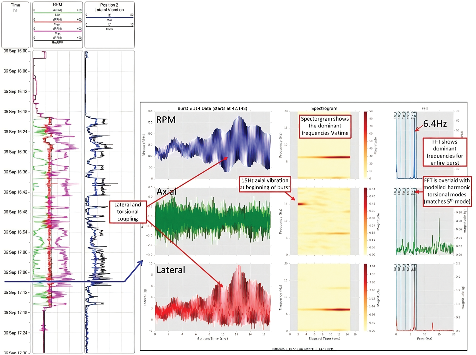
Figure 14: High-frequency vibration and their fast Fourier transform: Track 1: time (h), Track 2: RPM min (green), RPM mean (red), RPM max (violet), RPM rms (black), Track 3: lateral vibration position (max in blue, rms in black), Track 4: spectrogram and FFT of torsional, axial, and lateral vibrations
5 Case Study 2: Well-2 and Well-3
Similar to Well-1, the same MWD tool has been used to record the data from the two case study wells. This is because Well-2 and Well-3 are situated in the same petroleum field, and the geological layers are identical to those found in Well-1. Vibrations were detected on the same phase section (16 inches). Fig. 15 illustrates the compressive strengths of Well-2 and Well-3, as determined from previously drilled wells.
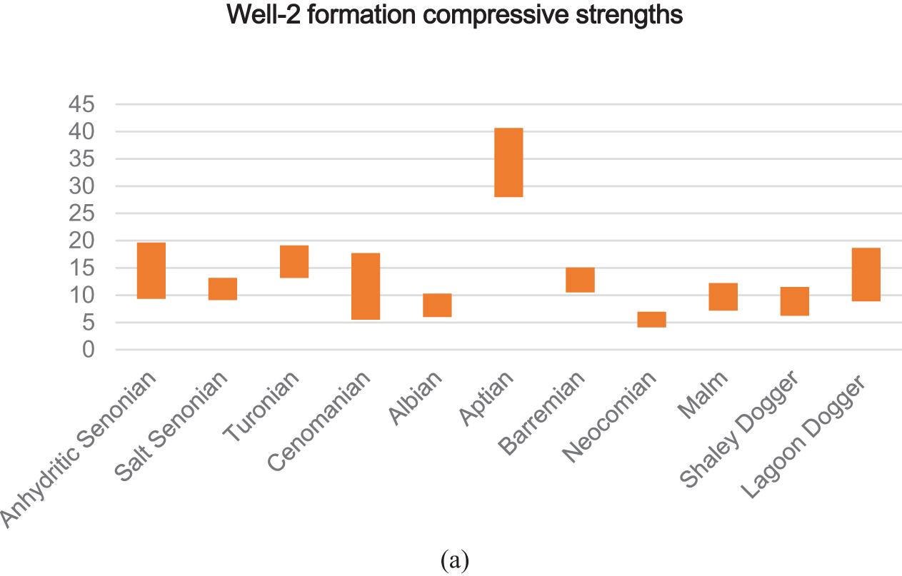
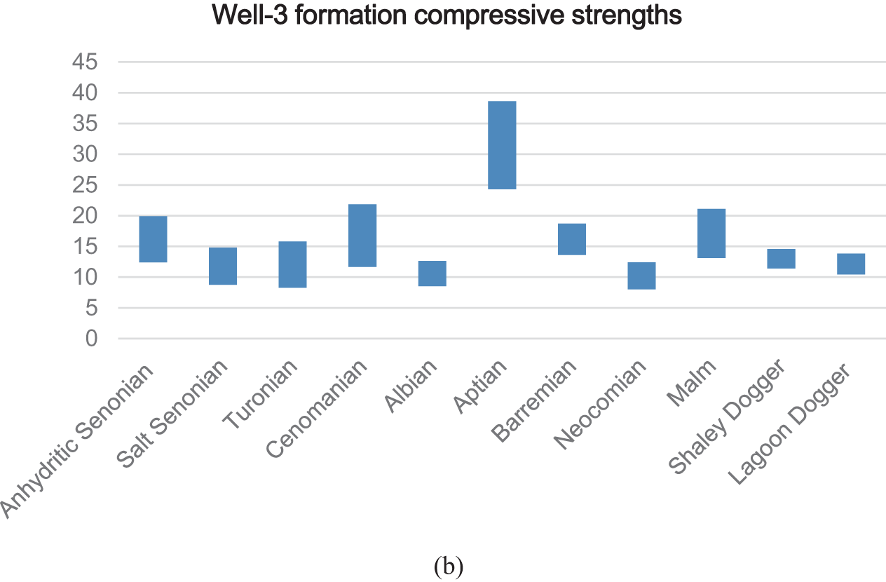
Figure 15: Compressive strength of different geological layers at (a) Well-2, (b) Well-3
Fig. 16 shows the root mean square (RMS) and maximum lateral vibrations for different geological layers at Well-2, along with the drilling performance. The drilling system exhibited significant lateral vibrations, even in the absence of high-frequency torsional vibrations. This is supported by the findings illustrated in Fig. 17. High-frequency lateral vibrations are caused by the proximity of salt formations.
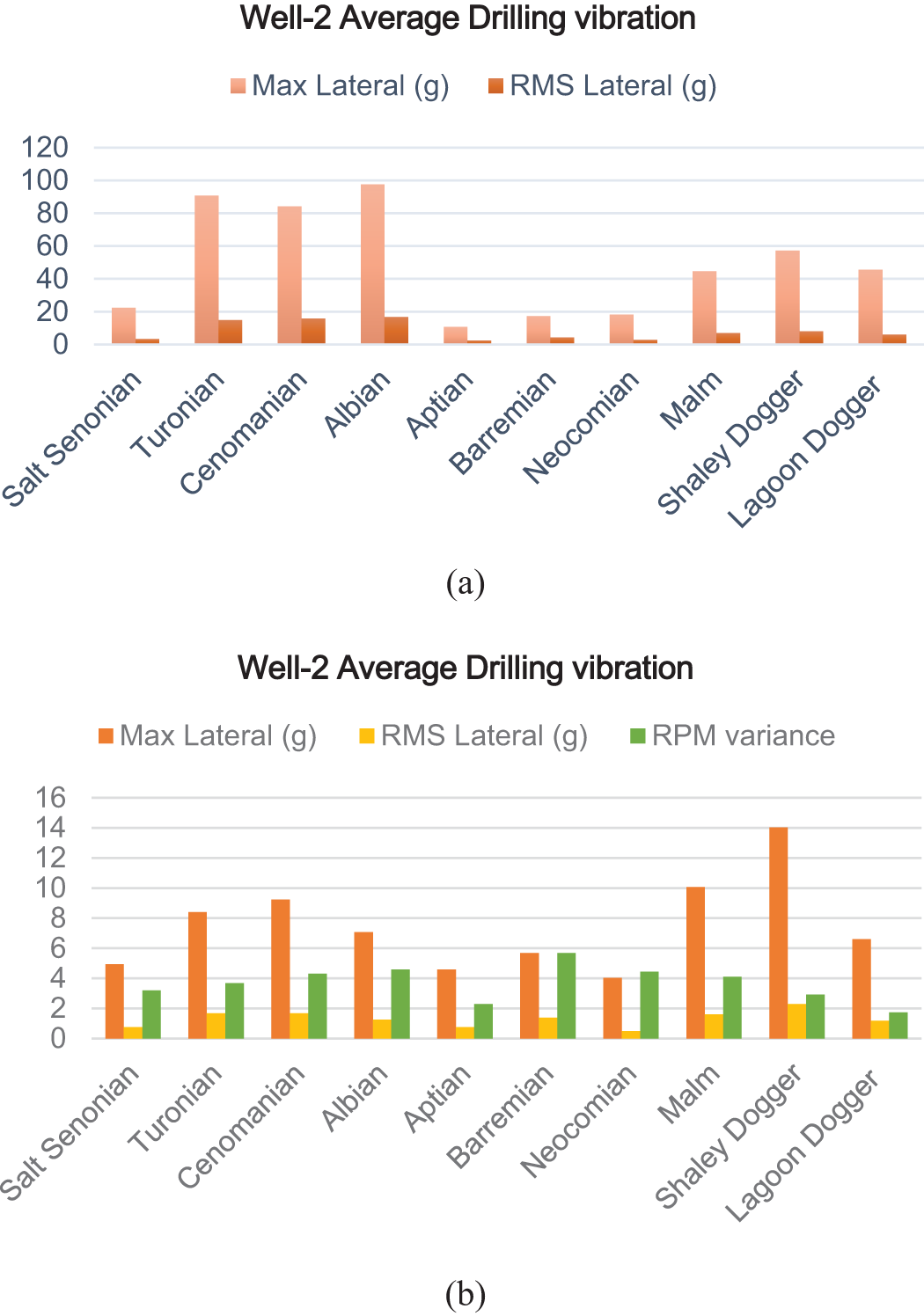
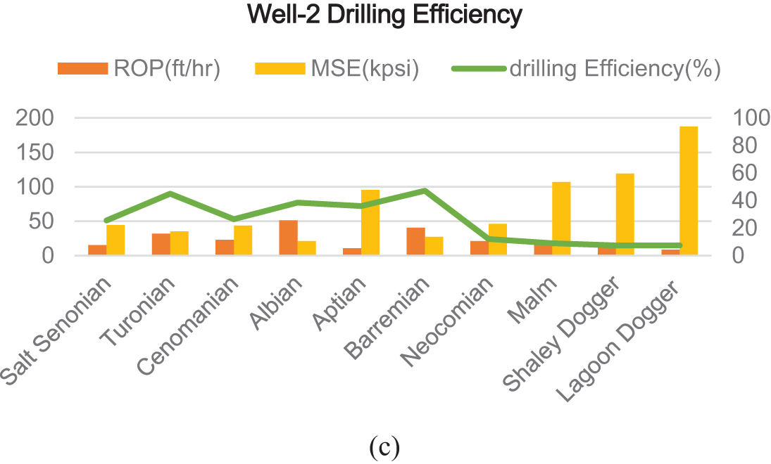
Figure 16: Measurement at Well-2: (a) lateral vibrations, (b) torsional vibrations, (c) drilling performance
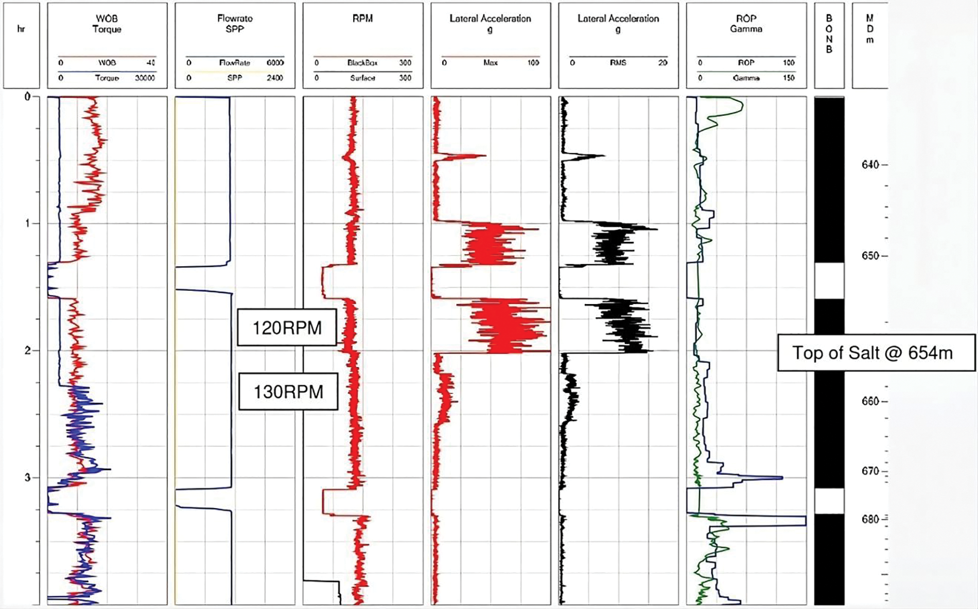
Figure 17: Measurement at Well-2: Track 1: time (h), Track 2: WOB (red), Torque (blue), Track 3: flowrate (blue), SPP (yellow), Track 4: RPM (bottom red, black surface), Track 5: lateral acceleration at Position 1 (red), Track 6: lateral acceleration (black), Track 7: ROP (blue), gamma-ray (green), Track 8: BONB, Track 9: MD
5.1 Well-2 Vibration Analysis Summary
An examination of the drilling procedure has revealed a notable issue with lateral movement, which has been determined to be one of the main factors behind the harm and chipping of the cutters. The occurrence of significant lateral shocks in the early stages is the cause of the initial damage to the drill bit. The continuous lateral oscillation persists throughout the Malm and Shaley Dogger formations, indicating a persistent issue with the performance of the drill bit. Fig. 17 shows that the twisting stability remains significant over the entire run, even when using roller reamers and a 5.5'' drill pipe. Nevertheless, it is worth mentioning that there is a decrease in drilling efficiency when dealing with claystone. This suggests that more research is required on the drilling method used in these geological layers.
Fig. 18 shows the RMS and maximum lateral vibrations measured at various rock layers in Well-3. The drilling system exhibited significant lateral vibrations, despite the absence of high-frequency torsional vibrations. The findings illustrated in Fig. 19 substantiate this. The drilling’s proximity to the Malm geological formations most likely causes the presence of these high-frequency lateral vibrations.
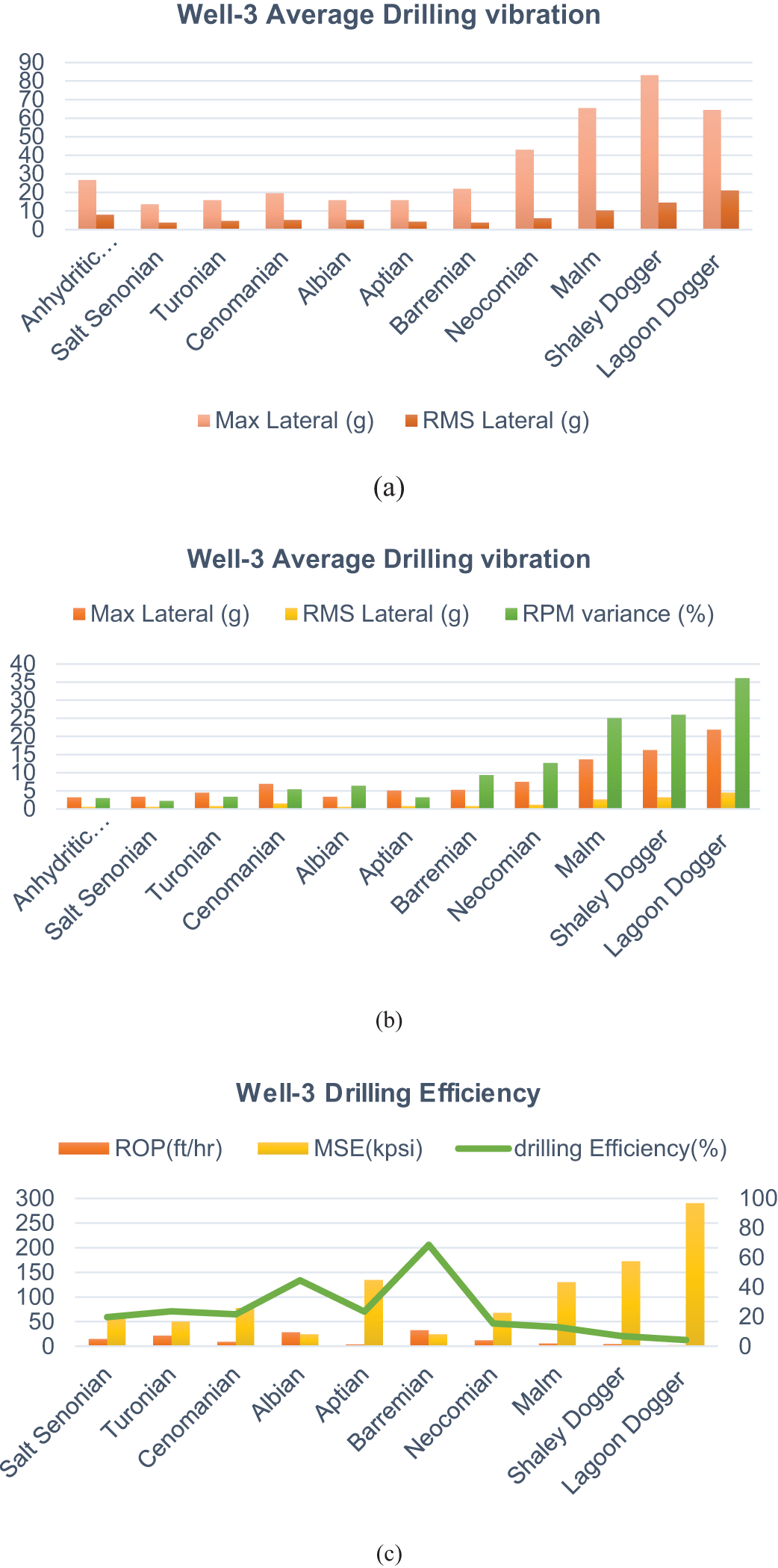
Figure 18: Measurement at Well-3: (a) Lateral vibrations, (b) Torsional vibrations, (c) Drilling performance
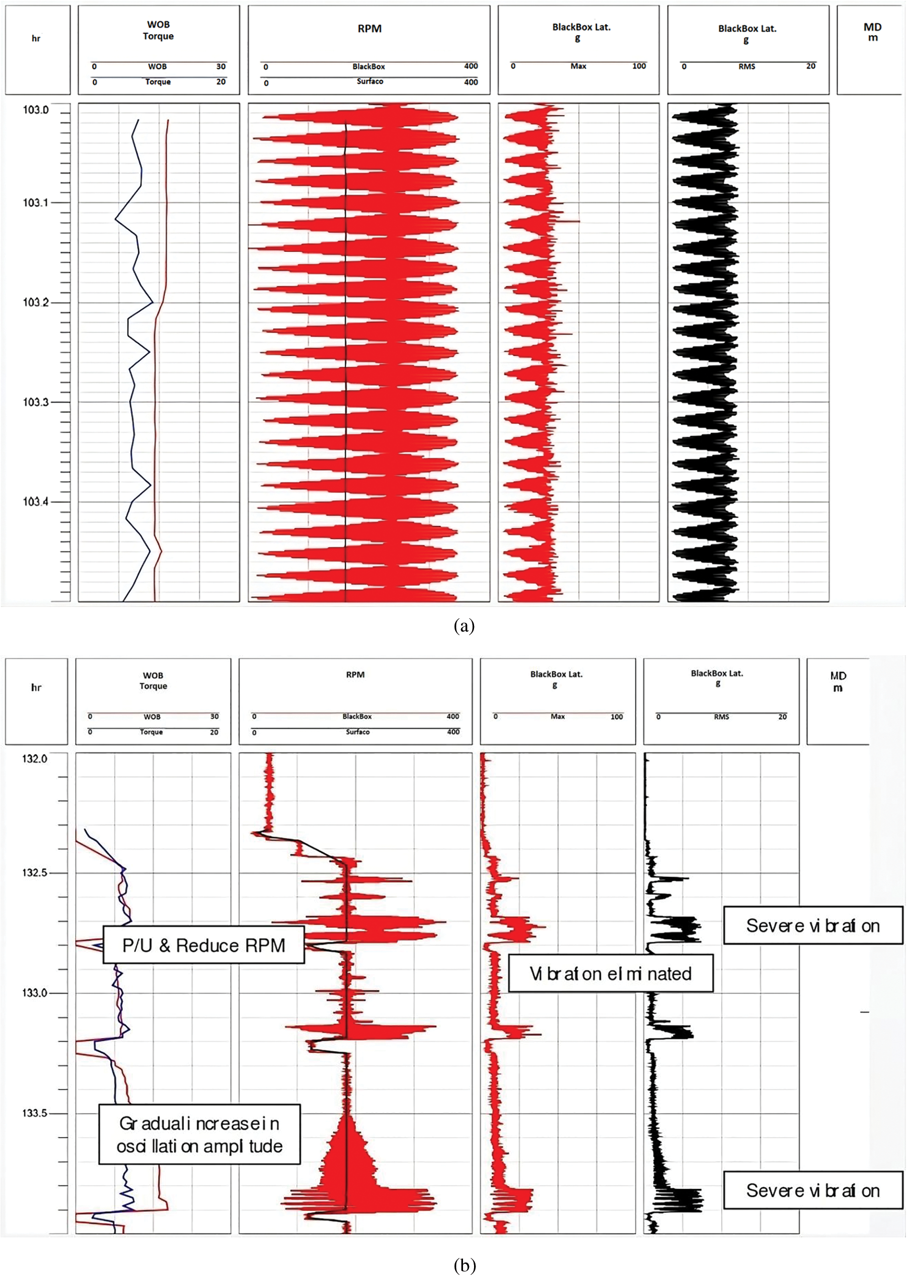
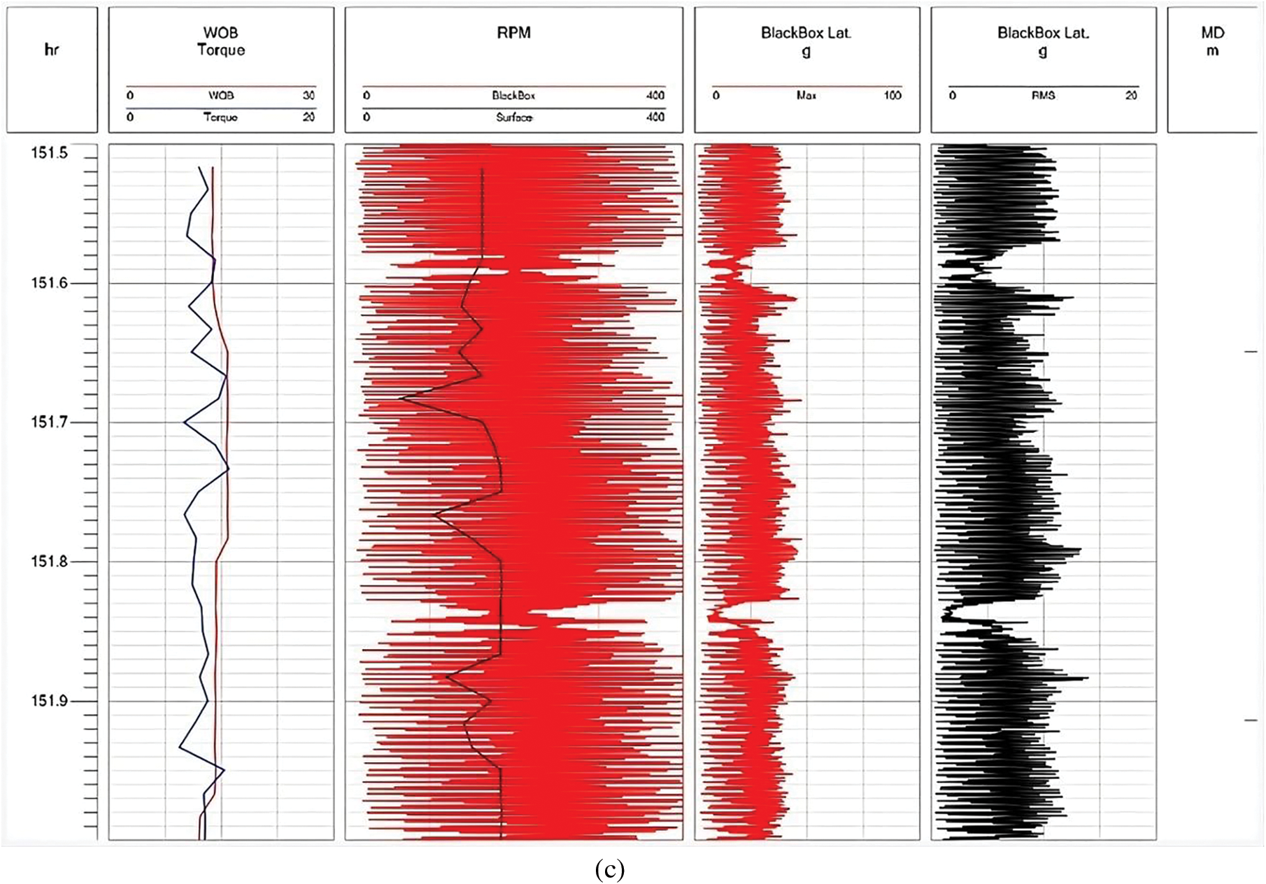
Figure 19: Measurement at well-3: (a) around fixed depth, (b) sever vibrations, (c) increased high-frequency severe vibrations, Track 1: time (h), Track 2: WOB (red), torque (blue), Track 3: flowrate (blue), SPP (yellow), Track 4: RPM (bottom red, black surface), Track 5: lateral acceleration at position 1 (red), Track 6: lateral acceleration (black), Track 7: ROP (blue), gamma-ray (green), Track 8: BONB, Track 9: MD
The examination of the drilling dynamics demonstrated significant torsional and lateral vibrations, distinguished by a prominent beating phenomenon measured at different time intervals as shown in Fig. 19a,b. This results in substantial fluctuations in the RPM, as depicted in Fig. 19c. The beating phenomenon occurs when two identical vibration frequencies affect each other, causing significant and periodic fluctuations in RPM. The simultaneous presence of these two frequencies indicates a strong interaction between torsional and lateral vibrations, which contributes to the observed difficulties in drilling. Additional analysis is required to understand the underlying factors contributing to this phenomenon of beating as well as the connection between these vibration frequencies. This analysis is necessary to develop effective strategies to reduce the impact and improve the efficiency of drilling operations.
In Fig. 20, the analysis of drilling operations reveals an annoying increase in both severe torsional and lateral vibrations in the lower formations. The vibrations intensify as the drilling goes deeper. The increased severity of the situation is accompanied by visible damage to the drill bit, necessitating an extra run of the bit to fix the reduced RPM. A notable observation of a beating phenomenon indicates that the top drive control system may be adding an extra frequency to the vibrational dynamics. An effective solution to address this problem is to introduce a higher surface RPM, which has a beneficial impact on decreasing the occurrence of the observed beating phenomena. This analytical discourse emphasizes the intricate interaction of multiple elements that impact drilling performance, as well as the importance of adaptive control strategies to enhance drilling efficiency and tackle potential challenges.
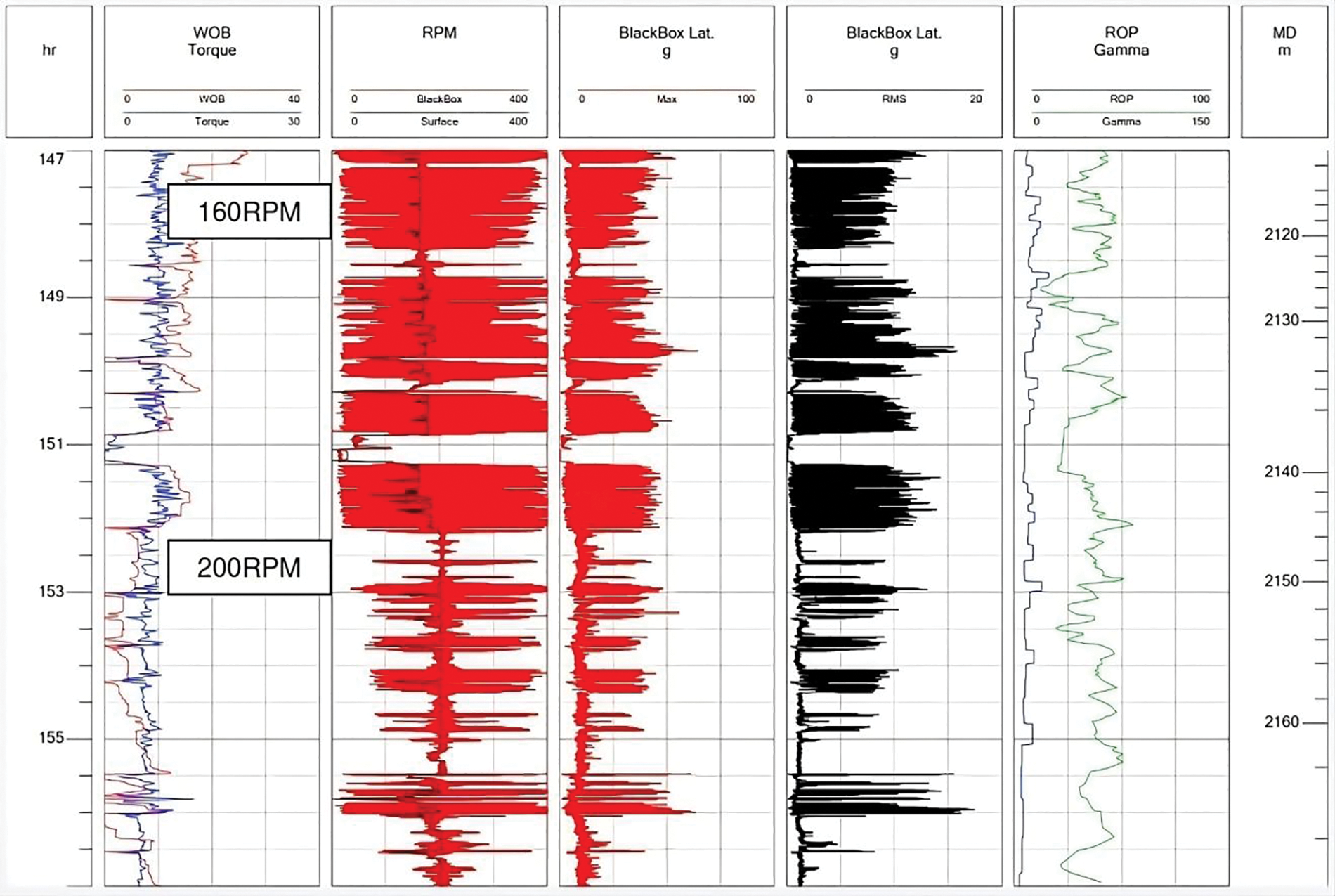
Figure 20: Vibration’s severity reduced at 200 RPM after considerable time
In order to confirm the declared conclusive remarks, a comparative analysis between the results in Well-2 and Well-3 has been conducted. Fig. 21a shows the average maximum lateral vibrations of each geological formation, Well-2 and Well-3. Fig. 21b shows the average torsional vibrations for each geological formation, Well-2 and Well-3.
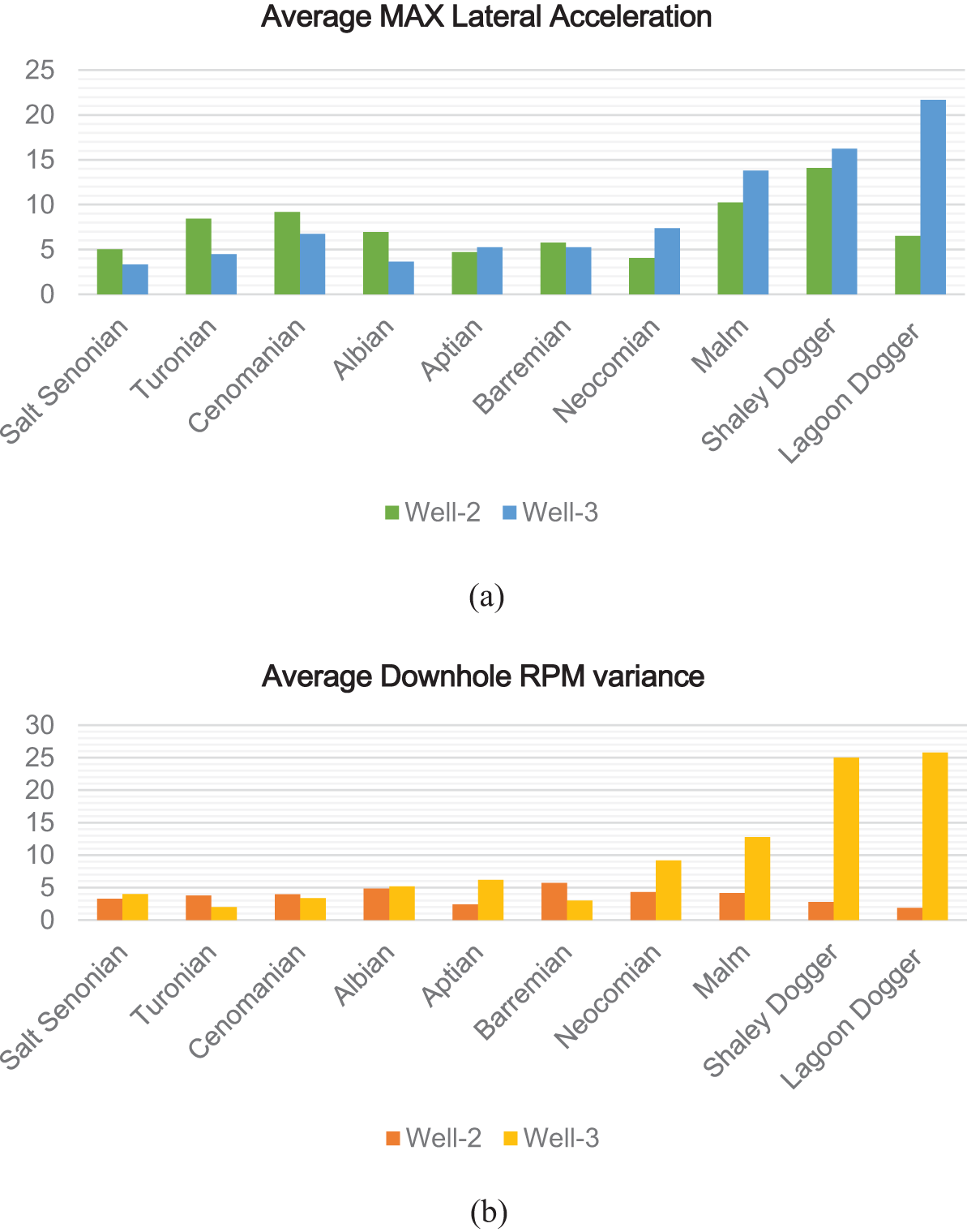
Figure 21: Vibrations profile comparison between well-2 and Well-3: (a) lateral vibrations, (b) torsional vibrations
As shown in Fig. 21a, Well-2 and Well-3 exhibited unique characteristics during drilling operations. Well-2 experienced early lateral shocks, resulting in damage to the drill bit. On the other hand, Well-3 encountered a distinct phenomenon known as beating, which was characterized by significant vibrations with a high amplitude. As a result, the drilling speed decreased, and an extra round of drilling was required. The beating observed in Well-3 is thought to be a result of the malfunctioning top drive control system, which may be connected to the decreased torsional rigidity caused by the use of a smaller drill pipe. Both wells had diminished efficacy while drilling into claystone formations, indicating the necessity for more examination of probable hydraulic issues. To investigate the detected irregularities on Well-3, supplementary MWD logs are recommended. This involves adjusting the control system parameters to optimize the dynamic circumstances in the downhole environment.
To promote torsional stability in both cases, it is advocated to maintain a steady rotational speed of 200 RPM when drilling into the Malm and Shaley Dogger formations. Furthermore, enhancing the hydraulic performance of the drill bit and using roller reamers in conjunction with a 5.5'' drill pipe are suggested strategies. The drilling process is marked by periods of substantial axial and lateral bit vibrations, which pose a particular challenge in the hard carbonate intervals that extend from the anhydritic Senonian to the Aptian strata. Bit chatter, which occurs due to less than optimal cutter engagement, is one of the main factors contributing to these vibrations. This conversion is the most harmful technique seen throughout this section. The possibility of the vibrations intensifying into complete Stick-Slip phenomena, which are characterized by low- and high-frequency torsional vibrations, highlights the intricate nature of the drill string dynamics. The progression from bit chatter-induced axial vibration to high-frequency torsional vibration demonstrates the interaction between axial and torsional vibrations, establishing high-frequency torque oscillations as the primary excitation factor.
Furthermore, the obtained results highlight the crucial necessity for implementing thorough vibration monitoring and control measures in all drilling operations, in addition to the special issues found in Well-2 and Well-3. Drillers can enhance their ability to predict and minimize the effects of mechanical vibrations by using sophisticated monitoring tools and optimizing control parameters. Utilizing real-time data MWD logs to dynamically modify drilling settings can effectively maintain optimal performance and minimize the probability of equipment failure. Implementing advanced hydraulic performance measures, such as optimizing mud flow rates and managing pressure, can significantly improve drilling efficiency and stability. The findings of this study indicate that further investigation should prioritize the development of advanced models that consider the intricate interaction of axial, torsional, and lateral vibrations. These models have the potential to offer more precise forecasts of drilling performance in different geological situations, resulting in more efficient and robust drilling methods. In summary, these results emphasize the need to employ a comprehensive strategy to handle mechanical vibrations in rotary drilling systems. This strategy should involve the integration of cutting-edge technology, accurate control mechanisms, and ongoing monitoring to guarantee the durability and effectiveness of drilling operations.
This study comprehensively investigates the complex interactions of axial, torsional, and lateral vibrations in rotary drilling systems and their significant impact on the system’s performance. Through the comparison of field data and the performance of comprehensive interaction analysis, we have determined that these vibrations can lead to notable problems, including bit bounce, stick-slip, and lateral-induced bit bounce. The observed damage in the drill bit underscores crucial areas for design improvements, underscoring the need to mitigate bit chatter, particularly in demanding rock formations.
Our work has revealed the robust and intricate interplay between various vibration categories, which has a substantial impact on drilling efficiency and the longevity of the system. The results indicate that torsional vibrations, especially during the slip phase, directly cause lateral vibrations, which in turn worsen axial vibrations. Furthermore, axial vibrations have a significant impact on releasing stuck bits, highlighting the importance of taking these dynamic interactions into account when developing controllers to reduce high-frequency coupled vibrations (namely the 4th and 5th harmonics).
The study’s theoretical contributions encompass a more profound comprehension of the interconnected vibration dynamics and the formulation of interaction models that more accurately forecast drilling performance in diverse geological circumstances. Essentially, the study offers practical and implementable knowledge for field operations. This includes enhancing logging systems, upgrading drill bits, and creating strong controllers. The purpose of these guidelines is to reduce equipment damage, improve drilling efficiency, and prolong the lifespan of rotary drilling systems.
Future research should prioritize the development of complete models that consider the intricate interactions of axial, torsional, and lateral vibrations, especially in high-frequency modes. These models ought to incorporate real-time data to enhance the precision of forecasts regarding drilling performance in various geological environments. It is essential to invest in advanced vibration monitoring tools and real-time data processing systems to alter drilling parameters dynamically. This helps to maintain optimal performance and limit the risks of equipment failure. Furthermore, it is crucial to design adaptive control systems that can effectively mitigate high-frequency coupled vibrations by responding to changing drilling circumstances.
Acknowledgement: We thank the anonymous reviewers for their careful reading of our manuscript and their many insightful comments and suggestions.
Funding Statement: The authors received no specific funding for this study.
Author Contributions: The authors confirm contribution to the paper as follows: study conception and design: Mohamed Zinelabidine Doghmane, Sid Ahmed Tadjer, Abdelhakim Idir; data collection: Madjid Kidouche; analysis and interpretation of results: Sid Ahmed Tadjer, Kong Fah Tee, Sabrina Meddah, Abdelhakim Idir, Madjid Kidouche; draft manuscript preparation: Sabrina Meddah, Mohamed Zinelabidine Doghmane, Abdelhakim Idir. All authors reviewed the results and approved the final version of the manuscript.
Availability of Data and Materials: The data that support the findings of this study are available on request from the corresponding author. The data are not publicly available due to privacy.
Ethics Approval: Not applicable.
Conflicts of Interest: The authors declare that they have no conflicts of interest to report regarding the present study.
References
1. Choe Y, Kim G, Kim I, Cha J, Ri K, Han Y, et al. Influence of torsional stick-slip vibration on whirl behavior in drill string system. Geoenergy Sci Eng. 2023;227:211931. doi:10.1016/j.geoen.2023.211931. [Google Scholar] [CrossRef]
2. de Moraes Luciano PP, Marcelo AS. Drill-string vibration analysis considering an axial-torsional-lateral nonsmooth model. J Sound Vib. 2019;438:220–37. doi:10.1016/j.jsv.2018.08.054. [Google Scholar] [CrossRef]
3. Fallahi E. Investigation of coupled axial-lateral-torsional drillstring vibrations using a multi-body dynamics approach (Master Thesis). Memorial University of Newfoundland: Finland; 2014. [Google Scholar]
4. Ren F, Wang B, Chen S. Nonlinear modeling and qualitative analysis of coupled vibrations in a drill string. Int J Bifurcat Chaos. 2018;28(10):1850119. doi:10.1142/S0218127418501195. [Google Scholar] [CrossRef]
5. Chen J, Liao H, Zhang Y, Liang H, Liu C, Qi D. A torsional-axial vibration analysis of drill string endowed with kinematic coupling and stochastic approach. J Pet Sci Eng. 2021;198:108157. doi:10.1016/j.petrol.2020.108157. [Google Scholar] [CrossRef]
6. Fang P, Ding S, Yang K, Li G, Xiao D. Dynamics characteristics of axial-torsional–lateral drill string system under wellbore constraints. Int J Non Linear Mech. 2022;146:104176. doi:10.1016/j.ijnonlinmec.2022.104176. [Google Scholar] [CrossRef]
7. Volpi LP, Lobo DM, Ritto TG. A stochastic analysis of the coupled lateral-torsional drill string vibration. Nonlinear Dyn. 2021;103:49–62. doi:10.1007/s11071-020-06099-z. [Google Scholar] [CrossRef]
8. Khulief YA, Bashmal S, Al-Sulaiman FA. Coupled torsional vibrations in drilling systems. In: ASME International Mechanical Engineering Congress & Exposition, 2005. p. 999–1007. doi:10.1115/IMECE2005-80489. [Google Scholar] [CrossRef]
9. Ding S, Fang P, Li G, Lu J, Wang Y, Li Y, et al. Axial-torsional nonlinear vibration of bottom hole assembly in the air drilling technology. Petroleum. 2023. doi:10.1016/j.petlm.2023.05.001. [Google Scholar] [CrossRef]
10. Liu J, Wang J, Guo X, Dai L, Zhang C, Zhu H. Investigation on axial-lateral-torsion nonlinear coupling vibration characteristic of drilling string in ultra-HPHT curved wells. Appl Math Model. 2022;107:182–206. doi:10.1016/j.apm.2022.02.033. [Google Scholar] [CrossRef]
11. Liu J, Liang S, Chen Y, Zhang M. Axial-lateral-torsional coupling nonlinear vibration of riserless drill-string considering both seawater and stratum parts. Appl Ocean Res. 2023;140. doi:10.1016/j.apor.2023.103742. [Google Scholar] [CrossRef]
12. Yu T, Li X, Zhang H, Duan C, Zeng H, Agila W. Nonlinear analysis of axial-torsional vibration of drill string based on a 3 DOF model. Adv Mech Eng. 2022;14(6). doi:10.1177/16878132221107778. [Google Scholar] [CrossRef]
13. Choe Y, Jin H, Kim G, Ri K, Yu K, Ri H. Axial-torsional mode correlation analysis of a drill string system with non-smooth characteristics. J Pet Sci Eng. 2022;218:110870. doi:10.1016/j.petrol.2022.110870. [Google Scholar] [CrossRef]
14. Guo X, Liu J, Wang J, Zhu H. Investigation on axial-lateral-torsion nonlinear coupling vibration model of drilling string in Ultra-HPHT curved wells. In: ASME 2021 Onshore Petroleum Technology Conference, 2021 Sept 27–29; ASME. doi:10.1115/OPTC2021-67533. [Google Scholar] [CrossRef]
15. Khulief YA, Al-Sulaiman FA, Bashmal S. Vibration analysis of drillstrings with self-excited stick-slip oscillations. J Sound Vib. 2007;299(3):540–58. doi:10.1016/j.jsv.2006.06.065. [Google Scholar] [CrossRef]
16. Tian J, Mao L, Yang Y, Song H, Song J. Study on directional drilling coupling dynamics based on drill string rotary controller. J Comput. Nonlinear Dynam. 2023;18(9):091008. doi:10.1115/1.4062911. [Google Scholar] [CrossRef]
17. Saldivar Márquez MB, Boussaada I, Mounier H, Niculescu S-I. Analysis and control of oilwell drilling vibrations, a time-delay system approach. Advances in Industrial Control. Switzerland: Springer; 2015. doi:10.1007/978-3-319-15747-4. [Google Scholar] [CrossRef]
18. Liu Y, Ma L, Li R, Chen B, Guo Y. Analysis of the longitudinal-bending-torsional coupled vibration mechanism of the drilling of a roof bolter for mine support system. Math Probl Eng. 2022;2022(1):4279959. doi:10.1155/2022/4279959. [Google Scholar] [CrossRef]
19. Al Dushaishi MF, Nygaard R, Stutts DS. An analysis of common drill stem vibration models. ASME J Energy Resour Technol. 2018;140(1):012905. doi:10.1115/1.4037682. [Google Scholar] [CrossRef]
20. Tian J, Liu Y, Xiong J, Wen F, Liu G. Analysis of drill string’s vibration characteristics based on sliding mode-PI controller. J Vib Eng Technol. 2022;10:919–27. doi:10.1007/s42417-021-00419-2. [Google Scholar] [CrossRef]
21. Riane R, Doghmane MZ, Kidouche M, Djezzar S. Observer-based h∞ controller design for high frequency stick-slip vibrations mitigation in drill-string of rotary drilling systems. Vibration. 2022;5:264–89. doi:10.3390/vibration5020016. [Google Scholar] [CrossRef]
22. Meddah S, Idir A, Tadjer S-A, Doghmane MZ, Kidouche M. PID control design of strongly coupled axial-torsional vibrations in rotary drilling systems. Przeglad Elektrotechniczny. 2024;3:196–201. doi:10.15199/48.2024.03.35. [Google Scholar] [CrossRef]
23. Kessai I, Benammar S, Doghmane MZ, Tee KF. Estimation of circular arc crack depths and locations in rotary drilling pipes subjected to free vibrations. Vibration. 2022;5(1):165–82. doi:10.3390/vibration5010011. [Google Scholar] [CrossRef]
24. Riane R, Doghmane MZ, Kidouche M, Tee KF, Djezzar S. Stick-slip vibration suppression in drill string using observer-based LQG controller. Sensors. 2022;22(16):5979. doi:10.3390/s22165979. [Google Scholar] [PubMed] [CrossRef]
25. Mendil C, Kidouche M, Doghmane MZ, Benammar S, Tee KF. Rock-bit interaction effects on high-frequency stick-slip vibration severity in rotary drilling systems. Multidiscip Model Mater Struct. 2021;17(5):1007–23. doi:10.1108/MMMS-10-2020-0256. [Google Scholar] [CrossRef]
26. Kessai I, Benammar S, Doghmane MZ, Tee KF. Drill bit deformations in rotary drilling systems under large-amplitude stick-slip vibrations. Appl Sci. 2020;10(18):6523. doi:10.3390/app10186523. [Google Scholar] [CrossRef]
Cite This Article
 Copyright © 2025 The Author(s). Published by Tech Science Press.
This work is licensed under a Creative Commons Attribution 4.0 International License , which permits unrestricted use, distribution, and reproduction in any medium, provided the original work is properly cited.


 Submit a Paper
 Propose a Special lssue
 View Full Text
 Download PDF
 Downloads
 Citation Tools