 Open Access
ARTICLE
Novel Methodologies for Preventing Crack Propagation in Steel Gas Pipelines Considering the Temperature Effect
1 Department of Architecture and Urban Planning, Mukhtar Auezov South Kazakhstan University, Shymkent, 160012, Kazakhstan
2 Department of Industrial Civil and Road Construction, Mukhtar Auezov South Kazakhstan University, Shymkent, 160012, Kazakhstan
3 Mechanics, Sound, & Vibration Laboratory, Department of Civil Engineering, College of Engineering, National Taiwan University, Taipei, 10617, Taiwan
4 Department of Reability & Dynamic Strength, A. Pidhornyi Institute of Mechanical Engineering Problems of National Academy of Sciences of Ukraine, Kharkiv, 61046, Ukraine
* Corresponding Authors: Nurlan Zhangabay. Email: ; Marco Bonopera. Email:
,
(This article belongs to the Special Issue: Health Monitoring and Rapid Evaluation of Infrastructures)
Structural Durability & Health Monitoring 2025, 19(1), 1-23. https://doi.org/10.32604/sdhm.2024.053391
Received 30 April 2024; Accepted 05 August 2024; Issue published 15 November 2024
Abstract
Using the software ANSYS-19.2/Explicit Dynamics, this study performed finite-element modeling of the large-diameter steel pipeline cross-section for the Beineu-Bozoy-Shymkent gas pipeline with a non-through straight crack, strengthened by steel wire wrapping. The effects of the thread tensile force of the steel winding in the form of single rings at the crack edges and the wires with different winding diameters and pitches were also studied. The results showed that the strengthening was preferably executed at a minimum value of the thread tensile force, which was 6.4% more effective than that at its maximum value. The analysis of the influence of the winding diameters showed that the equivalent stresses increased by 32% from the beginning of the crack growth until the wire broke. The increment in winding diameter decelerated the disclosure of the edge crack and reduced its length by 8.2%. The analysis of the influence of the winding pitch showed that decreasing the distance between the winding turns also led to a 33.6% reduction in the length of the straight crack and a 7.9% reduction in the maximum stresses on the strengthened pipeline cross-section. The analysis of the temperature effect on the pipeline material, within a range from −40°C to +50°C, resulted in a crack length change of up to 5.8%. As the temperature dropped, the crack length decreased. Within such a temperature range, the maximum stresses were observed along the central area of the crack, which were equal to 413 MPa at +50°C and 440 MPa at −40°C. The results also showed that the presence of the steel winding in the pipeline significantly reduced the length of crack propagation up to 8.4 times, depending on the temperature effect and design parameters of prestressing. This work integrated the existing methods for crack localization along steel gas pipelines.Keywords
The problem of crack propagation along main steel gas pipelines, in the form of avalanche fractures (destructions), is very common. Research has been carried out to solve this issue, most of which reinforced the pipe material and changed the operating conditions of the pipelines. These solutions, however, are not economically viable. For instance, in the Republic of Kazakhstan, this problem was aggravated by the fact that more than 70% of the national gas pipelines were in a deteriorated state [1]. According to Zhangabay et al. [2], open sources [3−6] showed that the main factors that influenced the operation of gas pipelines included pipe material corrosion, stress concentration in structural parts, and structural defects, as well as external influences that resulted in internal pressure and exposure to destructions [7−10]. These factors have led to accidents and human and environmental disasters [11–14]. As mentioned above, the solutions to such problems have been studied by various scientists and specialists. For example, Ilincă [15] presented a case study of the bursting of a buried gas pipeline, which aimed to identify the cause of the incident and improve the strength of the pipeline under external loads. It evaluated whether a 20-inch pipeline near road crossings could withstand external loads under corrosion conditions. Such a study was performed based on a finite-element (FE) method where a solution was ultimately proposed to improve the pipeline strength characteristics by introducing protection sleeves equipped with spacer rings. However, only underground pipelines were considered in their work. Mahmood et al. [16] conducted a study based on a review of several gas pipeline accidents, identifying the material and age as critical factors threatening pipeline integrity and leading to corrosion damage. As a result, they proposed a targeted risk mitigation strategy to avoid structural failure, which was of fundamental importance for minimizing the risks associated with pipeline networks. Biagio et al. [17] investigated the roles of structural pipeline geometry, material ductility, and strain hardening on the propagation of ductile cracks [18]. Yang et al. [19] performed a theoretical and experimental study of crack modeling, investigating the crack propagation velocity and gas decompression. Their results demonstrated that, under certain conditions, the crack propagation rate was below the gas pressure break rate, which implied that the prototype pipeline could terminate its breaking. Conversely, Zhang et al. [20] numerically investigated the steel grade of gas pipelines with different corrosion depths that were subjected to internal pressure, showing the influences of the characteristics of the pipe material and cracking varieties that might minimize the damage. Kaputkin et al. [21] proposed a method by changing the configuration of the pipeline cross-section to deal with crack propagation, while Kaputkin et al. [22] provided the classification of the fractures concerning the temperature effect. Shtremel et al. [23] studied the rate of crack propagation on a large pipeline cross-section, with a diameter of 1420 mm, finding that on the large cross-section, the rate of crack propagation became smaller than the initial value by 1.5–2 times. This was due to a decrease in speed which led to the stoppage of crack development in the longitudinal direction. Based on the results of the aforementioned studies, it is concluded that numerical modeling of crack propagation in steel gas pipelines should be conducted based on dynamic deformation models that consider the plastic properties of the materials. Additionally, the strain rate influence on the matter failure and plastic yield process should be considered [24]. To account for the influence of temperature on the process of structure failure, the mathematical model of the problem should incorporate the dependency of stresses on deformations as functions of time and temperature [25]. The problem of deformation and failure of reinforced steel gas pipelines was not previously investigated in such a formulation. According to the literature review, the task that aims to implement methods for the localization of crack propagation in large-diameter pipeline cross-sections under different temperatures requires further studies. Furthermore, in previous works and the existing national [26–28] and international standards [29–33], cost-effective methods for the localization of crack propagation were not proposed. Only changes in the geometric parameters of the pipes and corresponding operational conditions were proposed, which were not acceptable in most cases.
This work is a continuation of a series of investigations dealing with the deformation and failure of main gas pipeline cross-sections with cracks. First, the stressed-deformed state, the break of the steel pipeline cross-section with an initial crack, as well as those in the crack tip area, were investigated by Zhangabay et al. [34]. In the second stage, Zhangabay et al. [35] investigated crack propagation under conditions of temperature loading on the pipe material. Subsequently, targeting the outcomes obtained from the analysis of crack propagation, an approach for the localization of avalanche fractures was proposed according to the prestressing method, which was described in Zhangabay et al. [36–39]. This work is dedicated to developing numerical methodologies for analyzing the influences of the parameters of wire-wound sections of pipes with cracks on the longitudinal crack propagation in steel gas pipelines. Numerical modeling of the dynamic strength was based on a mathematical model that considered the nonlinear relationship between stress, strain, strain rate, and temperature. The deformation process was modeled in four stages: elastic deformation, small plastic deformation, large plastic deformation, and local material failure. Particularly, the material failure was modeled based on the maximum stress criterion (Von Mises’s criterion). The mechanical properties of the material, dependent on the ambient temperature, were investigated as working temperature ranged from
The stressed-deformed state of the gas pipeline was studied by examining the thermo-elastic-plastic features of its steel matter [40]. The constitutive equation of the steel’s elastic state took the following form:
The large-diameter cross-section of the Beineu-Bozoy-Shymkent steel gas pipeline with a straight crack was considered in this study. The crack was located in the central part of the pipeline and on its outer surface away from the supports. The thickness of the pipe cross-section was H, and the crack depth was a = 0.5 H. Assume H = 15.9 mm, and a = 8.0 mm. The crack was directed in the longitudinal direction of the pipeline and perpendicular to its axial section. Furthermore, its initial width was w = 1.0 mm, while the angle at the crack tip equaled 20°. The initial length of the non-through crack was assumed to be l = 200 mm [34,35]. Two variants of the reinforcement of the steel gas pipeline were considered in the novel methodology. The first variant adopted steel single rings at the edges of the crack (Fig. 1).
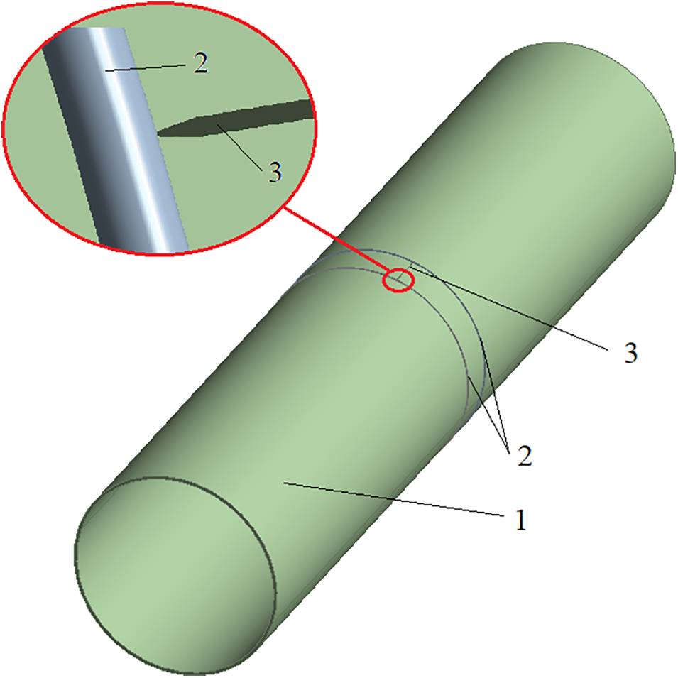
Figure 1: A schematic diagram of the steel gas pipeline with a straight crack reinforced by steel rings at the edges: 1) Pipeline; 2) Single steel rings; and 3) Straight crack
The second variant involved the steel wire wrapping reinforcement with different winding pitches, i.e., 2.0, 1.0, 0.5, and 0.25 m (Fig. 2).
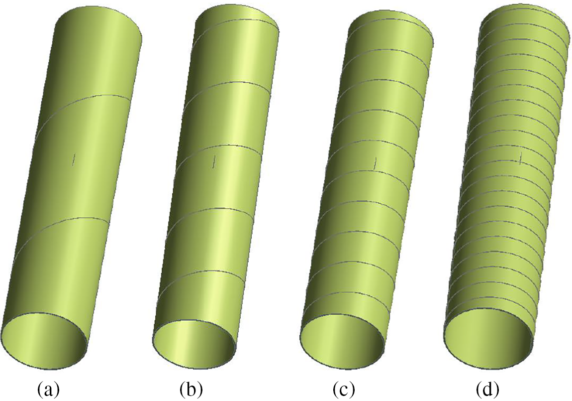
Figure 2: A schematic diagram of the steel gas pipeline with a straight crack reinforced by a steel wire wrapping with pitches of a) 2.0 m; b) 1.0 m; c) 0.5 m; and d) 0.25 m
Class X70 steel was used as the material of the pipeline cross-section, whilst class 65 steel was adopted for the winding material. Tables 1 and 2 present the mechanical characteristics of the pipe material (steel X70) and the winding material (steel 65) when the temperature range rose from −40°C to +50°C [41,42]. Such a temperature range was considered the operational zone for the Beineu-Bozoy-Shymkent gas pipeline.


It is noted that class X70 steel is a high-strength low-carbon micro-alloyed material with a high impact strength at low temperatures, so a temperature lower than
where

Unsteady internal pressure was defined according to Fig. 3 and based on the experimental data by Nordhagen et al. [43]. Its variations with time corresponded to three stages of loading. The first stage was when the growth of the working pressure was critical. The second stage had a constant critical pressure, whilst the third was when the pressure dropped due to the gas outflow from the through crack.
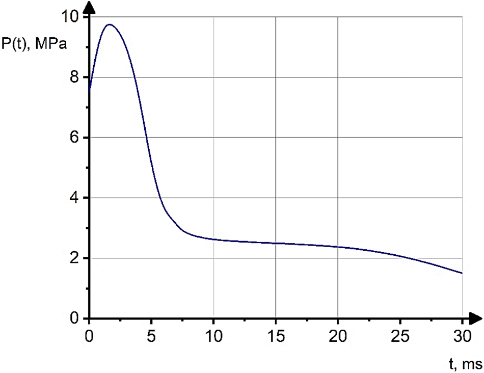
Figure 3: Variations of the unsteady internal pressure with time
A numerical solution to the problem was carried out using the FE software package ANSYS-19.2/Explicit Dynamics. As mentioned earlier, this work is a continuation of a series of investigations on avalanche destruction of main steel gas pipelines. The issue of longitudinal crack propagation along a steel pipeline was addressed by Zhangabay et al. [34]. During the construction of the FE model based on cylindrical shell elements, the solution convergence was observed. According to the relevant results, the FE mesh was fabricated with the “Element Size” set at a magnitude of 0.01. Additionally, the cylindrical shell FE quantity of the pipeline’s thickness was determined with the “Sweep Method” option. Consequently, a uniform mesh was generated, as depicted by Zhangabay et al. [34]. These results were utilized for constructing the FE mesh of the wire. Besides, the FE mesh of the wire was created with the “Element Size” parameter set at 0.001. The FE model, which described the steel pipe section’s dynamic stressed-deformed state and damage (considering the thermal action on the matter’s machinal properties), was outlined by Zhangabay et al. [35]. The FE modeling results of the crack development in the pipe without the wire were then used for validating this investigation.
3.1 Influence of the Tensile Force of the Wire Winding Filament on the Crack Propagation on the Steel Rings Located at the Ends of a Non-Through Crack
The FE section modeling results of the steel gas pipeline with a longitudinal crack (not reinforced by a steel wire) at temperatures of −
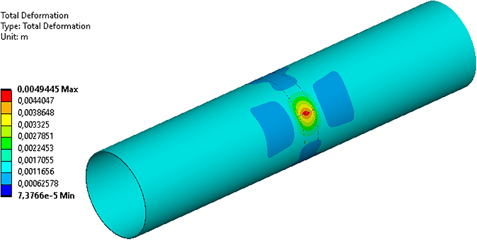
Figure 4: Elastic strains for P = 9.34 MPa at t = 0.8 ms (P: internal pressure)
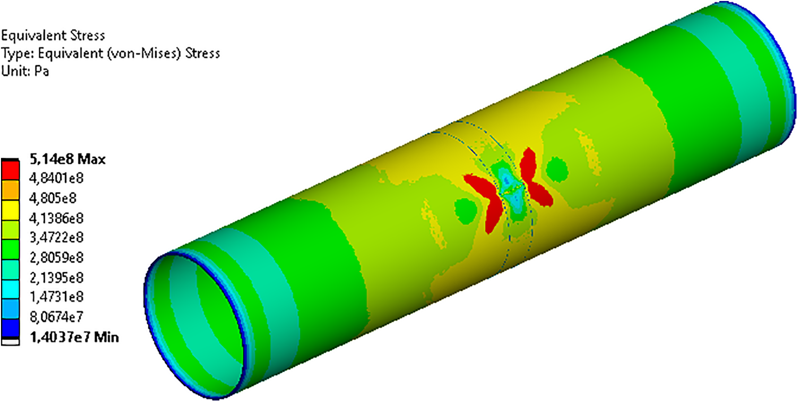
Figure 5: Stresses for P = 9.34 MPa at t = 0.8 ms (P: internal pressure) (Units: MPa)
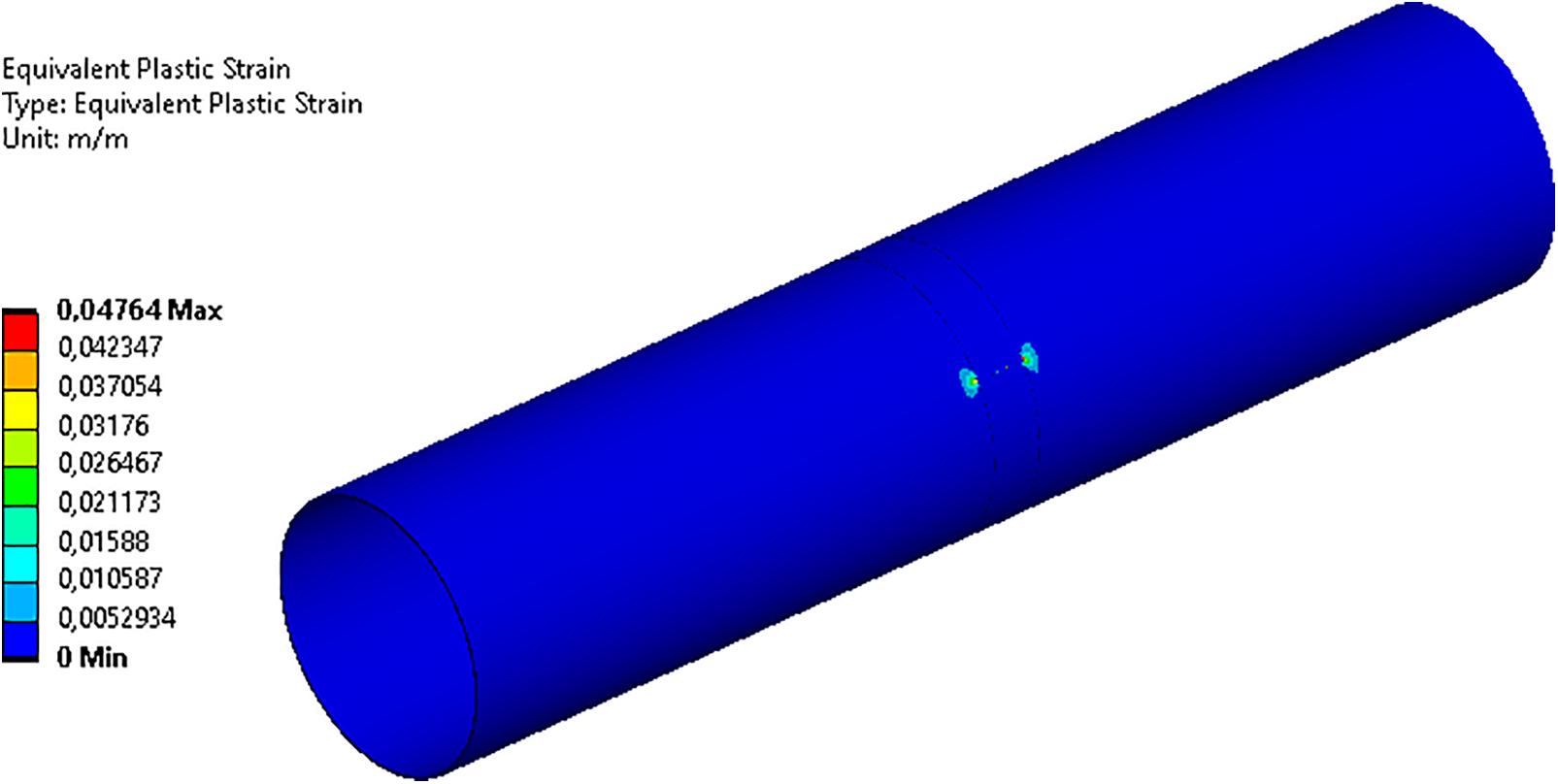
Figure 6: Plastic strains for P = 9.34 MPa at t = 0.8 ms (P: internal pressure)
The maximum elongations did not exceed 5.0 mm but were localized to the crack area. At the same time, the crack remained non-through.
The localization of stresses and plastic strains at the ends of the crack was observed. In short, the steel rings retained their integrity and prevented the crack opening. As the pressure further increased to and maintained at the critical value, the crack became a through one. The gas pressure at the crack edges led to the crack opening, which, in turn, was restrained by the steel rings. Figs. 7–9 respectively show the elongations, stresses, and plastic strains at t = 2.0 ms. By this point, the straight crack reached a length of 1.08 m. The steel rings maintained their integrity by restraining the crack opening, thus slowing down its growth along the longitudinal direction.
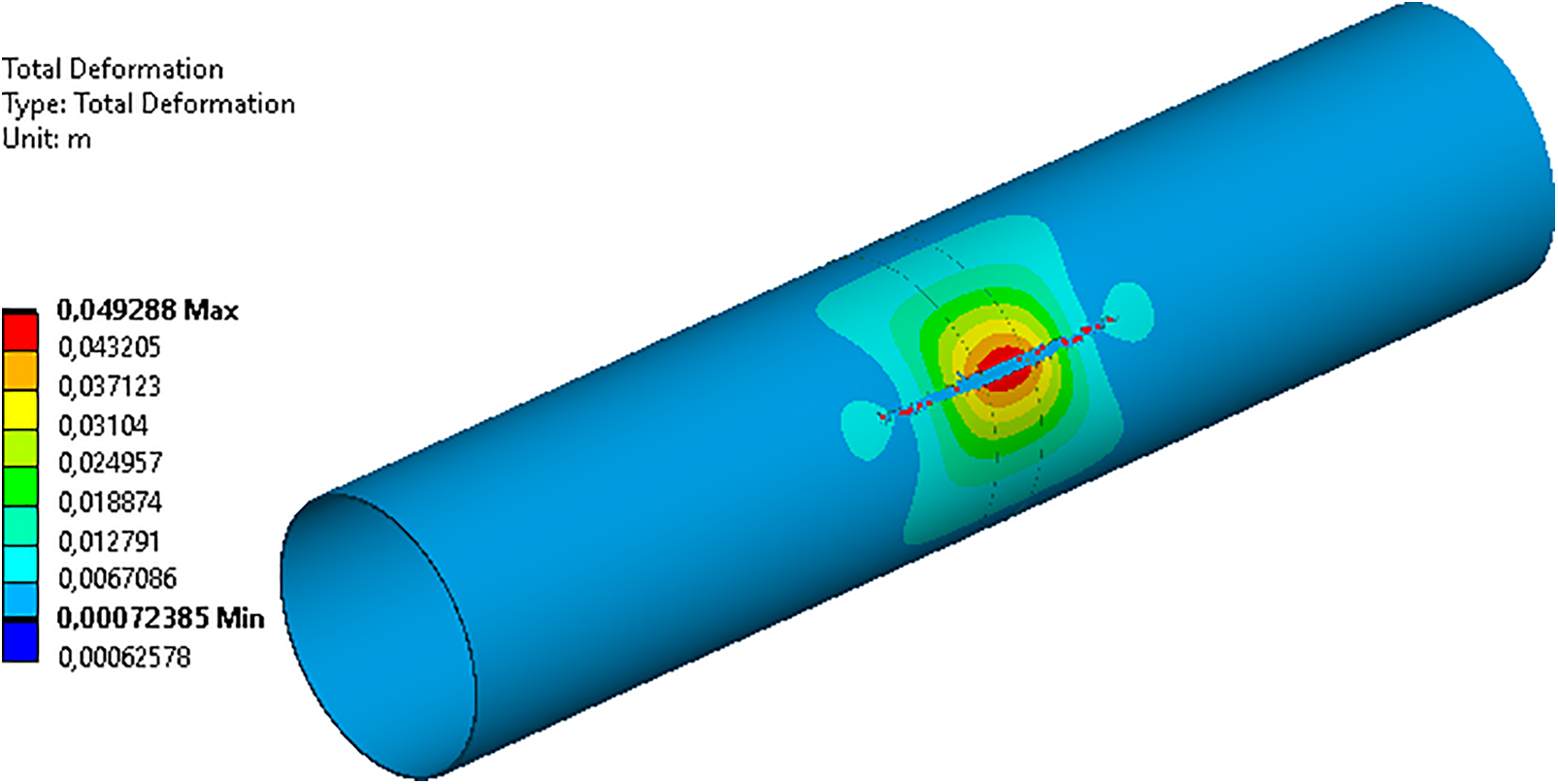
Figure 7: Elastic strains at t = 2.0 ms
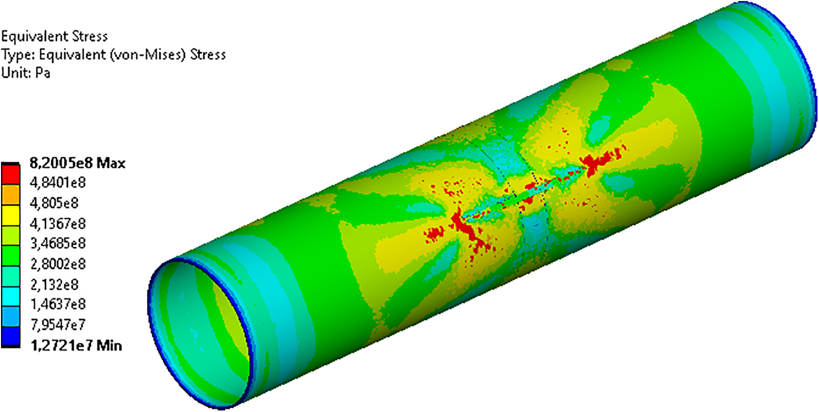
Figure 8: Stresses at t = 2.0 ms (Units: MPa)
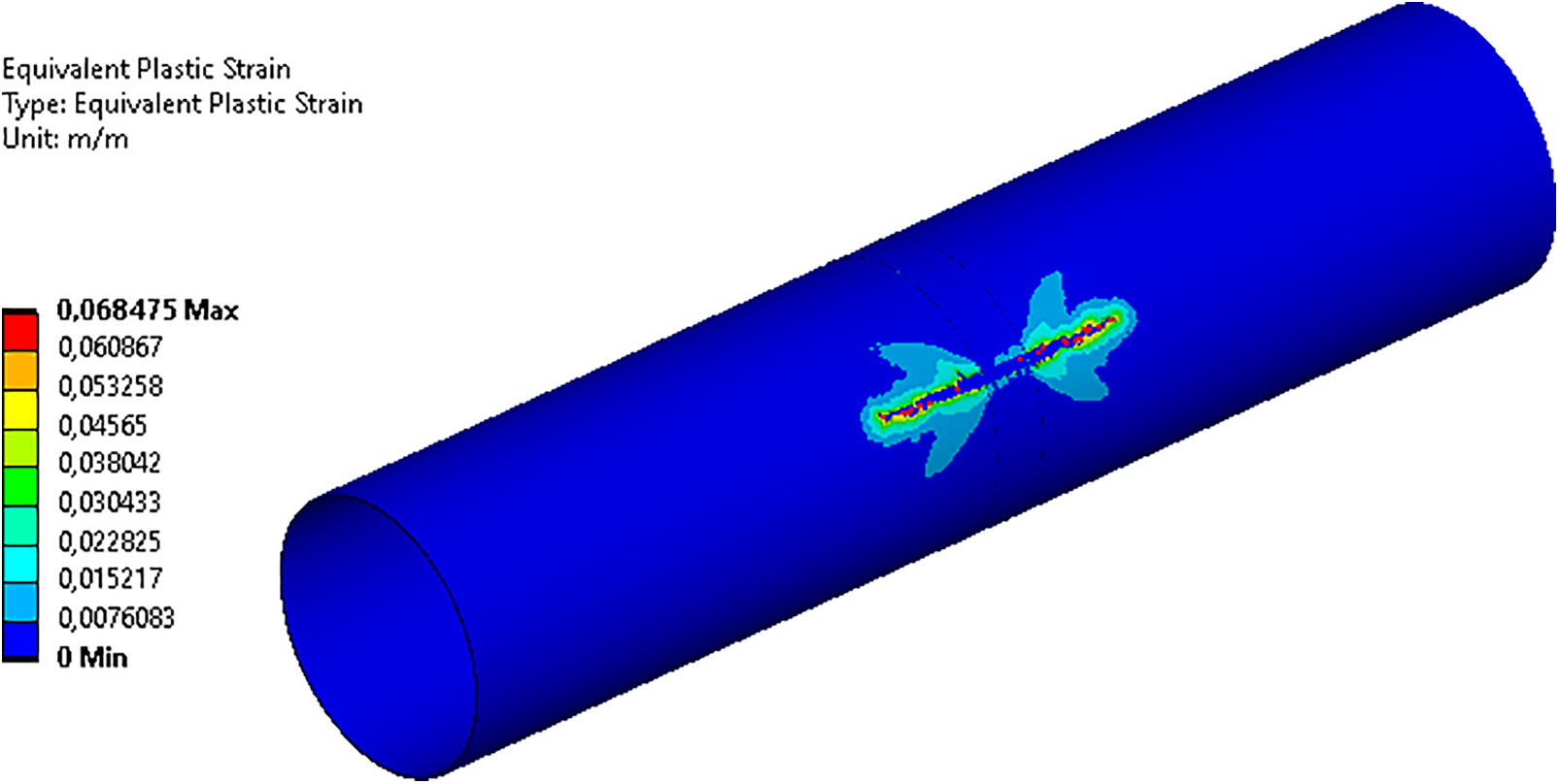
Figure 9: Plastic strains at t = 2.0 ms
Subsequent development of the crack did not occur along the longitudinal direction, as shown in Fig. 10. Over time, as the pressure decreased, the fracture of the damaged cross-section of the steel pipeline stopped.
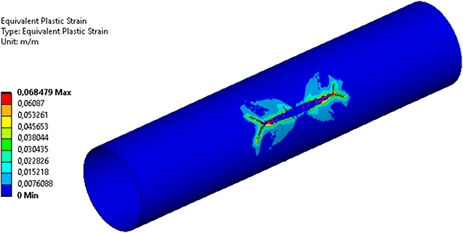
Figure 10: Plastic strains at t = 3.5 ms
Hence, the presence of the steel rings, at the initial stage of the strain, restrained the crack opening and reduced its rapid growth along the longitudinal direction. However, the increment of the internal pressure within the pipe cross-section till the critical values led to the formation of a through crack (and opened its edges). The opened edges put pressure on the steel rings, which also caused their fracture. Fig. 11 illustrates the plastic strains at t = 3.5 ms, which corresponds to the beginning of the ring fracture. Such a fracture occurred at the opened edge of the crack. Moreover, this failure was observed for all the investigated values of the thickness and tensile force applied to the steel wire. Conversely, no crack development along the longitudinal direction was observed after the ring fracture. This could be explained by the accelerated gas outflow through the opened crack, which led to a rapid drop in the internal pressure.
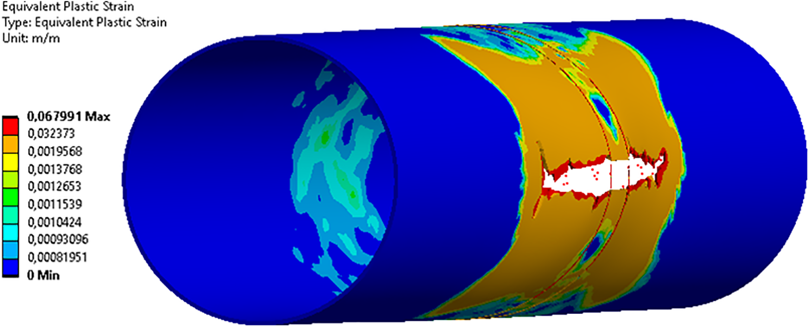
Figure 11: Plastic strains at k = 0.05 and t = 3.5 ms (k: coefficient for the tensile force of the steel winding in percentages)
Table 4 shows the values of the starting time of the ring fracture and the maximum crack lengths for k = 0.05, k = 0.25, k = 0.50, and k = 0.75.

The aforementioned numerical analyses showed that the steel rings with a higher initial tensile force fractured faster. Therefore, it was preferable to strengthen the cracks with the steel rings that had a minimal tensile force of the steel wire thread, e.g., at
3.2 Influence of the Diameter of the Wire Winding Filament on the Crack Propagation on the Steel Rings Located at the Ends of a Non-Through Crack
The effects of the filament diameter of the steel ring on the development of the through crack and the propagation distance of the through crack along the pipeline at the critical increment in internal pressure were investigated in this section. Specifically, three types of steel wire wrappings with different filament diameters, d1 = 4.0 mm, d2 = 5.0 mm, and d3 = 6.0 mm at

The aforementioned analyses showed that an increment in the wire diameter led to an increment of the fracture with time and, as a consequence, to a slowing down of the edge crack opening, which eventually reduced the crack length. The obtained results were uniform for all the design cases, so the results for a steel wire with a diameter of 6.0 mm are summarized below as an example. Figs. 12–14 respectively show the stresses of the pipeline cross-section with a crack at the beginning of its growth, i.e., at t = 1.58 ms; at the end of the crack growth along the longitudinal direction, i.e., at t = 3.15 ms; and corresponding to the rupture of the steel rings, i.e., at

Figure 12: Stresses at

Figure 13: Stresses at

Figure 14: Stresses at
Figs. 15–17 respectively show the deformations of the pipeline cross-section with a crack at the beginning of its growth at

Figure 15: Elastic strains at

Figure 16: Elastic strains at

Figure 17: Elastic strains at
Figs. 18–20 respectively depict the plastic strains of the pipeline cross-section with a crack at the beginning of its growth at

Figure 18: Plastic strains at

Figure 19: Plastic strains at

Figure 20: Plastic strains at
Based on the aforementioned analyses, it could be declared that the steel wire wrapping, under the form of rings at the ends of non-through straight cracks, prevented the avalanche fracture of steel gas pipelines at the working pressure. Furthermore, such a wire wrapping could reduce the crack propagation length in the longitudinal direction corresponding to the critical pressure. In this case, it was preferable to use a tensioned wire wrapping with a larger diameter and the lowest tensile force.
3.3 Influence of the Winding Pitch of the Wire Winding Thread on Crack Propagation
The cross-section of the steel gas pipeline with a non-through crack strengthened by a steel wire winding was investigated in this section. The wire winding was wound with a uniform pitch, whilst the mutual arrangement of winding turned and the crack was arbitrary. Particularly, the influence of the winding pitch of the steel wire winding thread on the strength and integrity of the cracked pipe cross-section was considered. For this purpose, four winding pitches, 2.0, 1.0, 0.5, and 0.25 m, were considered (Fig. 2). A steel wire with a diameter d = 6.0 mm, tensioned with a force of 1.38 kN, was considered in this case. The unsteady load was set according to Fig. 3. Fig. 21 shows the deformations to the cross-section of the hardened pipeline with a crack. The results were determined at t = 3.5 ms, which corresponded to the maximum development of the crack along the longitudinal direction.
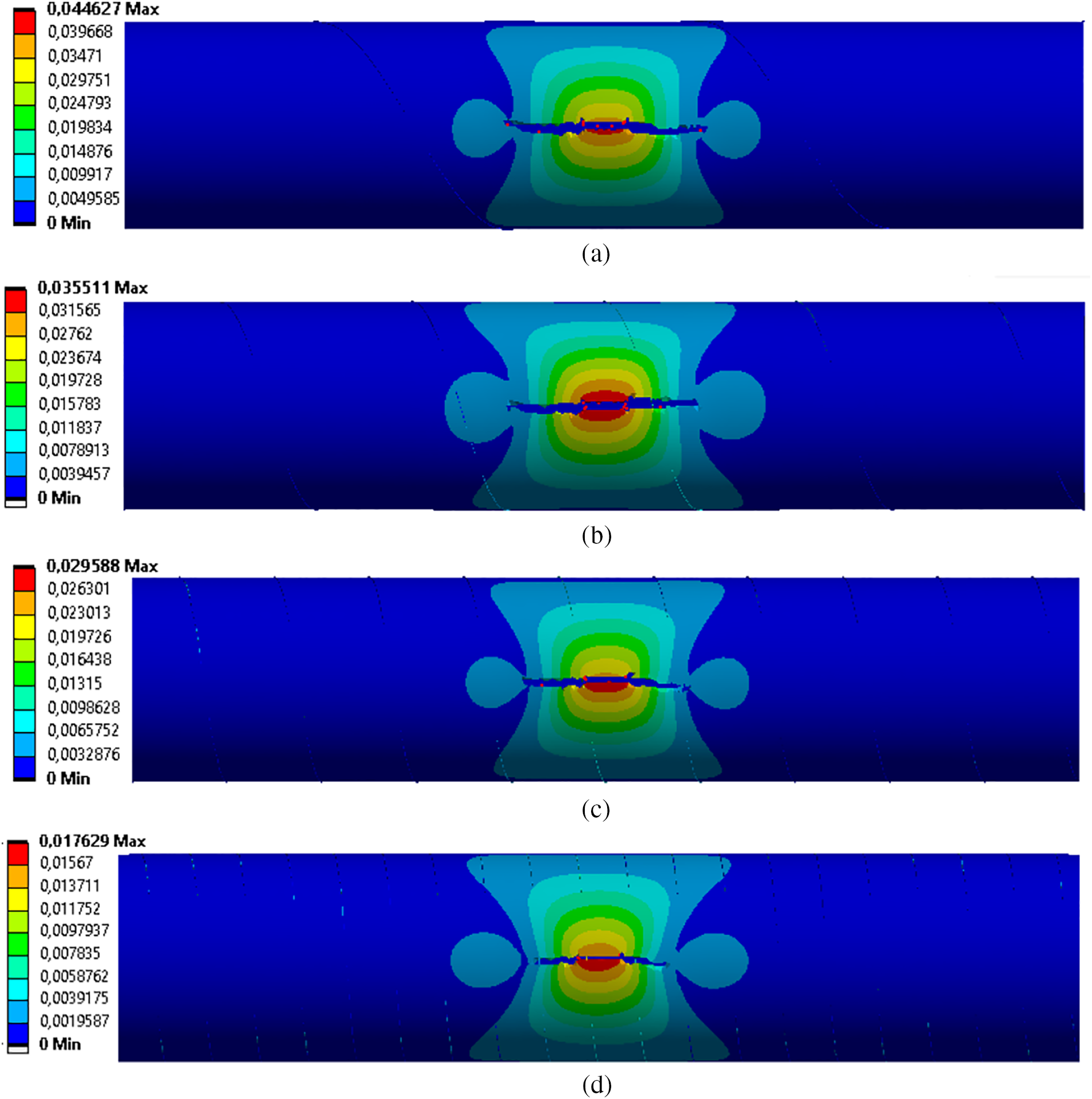
Figure 21: Elastic strains of the steel gas pipeline cross-section with a straight crack and reinforced by a steel wire wrapping with a pitch of (a) 2.0 m, (b) 1.0 m, (c) 0.5 m, and (d) 0.25 m
The analysis of the results showed that the reduction of the wire winding pitch in the steel winding led to the reduction of the maximum deformations in the pipeline cross-section. The area of maximum deformations corresponded to the initial location of the non-through crack. However, the critical load led to the formation of a through crack during the strain process, which developed in the longitudinal direction over time. In this case, the presence of the winding reduced the crack length. Table 6 summarizes the values of the straight crack length for each of the investigated winding pitches. Besides, reducing the spacing between the turns of the steel wire winding reduced the length of the linear crack.

Fig. 22 shows the stresses corresponding to the cross-section of the reinforced steel gas pipeline with a crack at
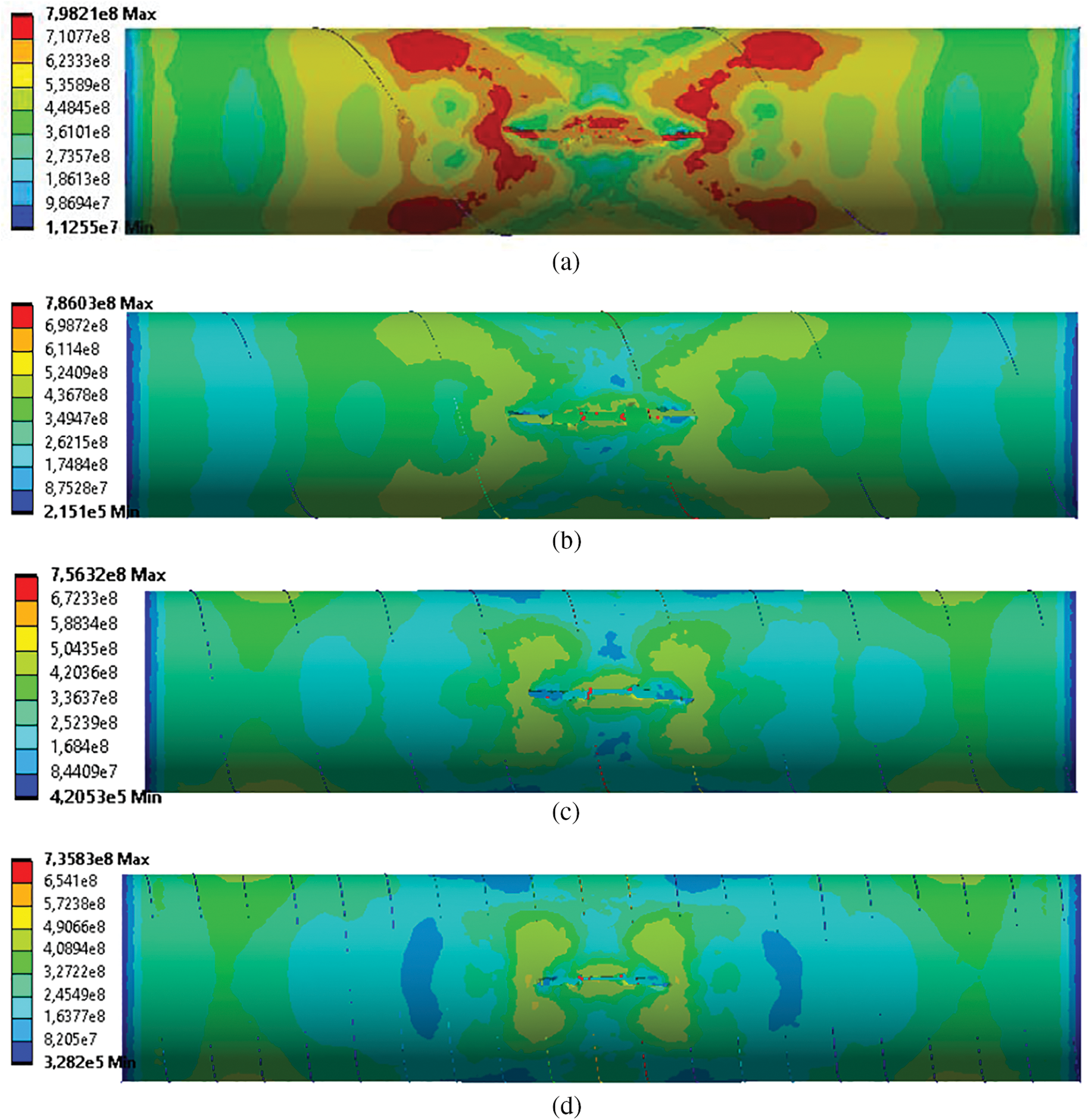
Figure 22: Stresses of the steel gas pipeline cross-section with a straight crack and reinforced by a steel wire wrapping with a pitch of (a) 2.0 m, (b) 1.0 m, (c) 0.5 m, and (d) 0.25 m (Units: MPa)
Notably, the reduction of the distance between the winding turns led to a slight stress reduction in the pipeline cross-section. An insignificant localization of the stresses was observed in the area of the crack tips. Investigations on the stress–state in the steel pipeline at the working pressure were performed here. Specifically, the pressure was given by a piecewise linear function: – Р(t) = Рkr·t when 0 ≤ t ≤ 1.0 ms, and – Р(t) = Рkr for t ≥ 1 ms. It was found that the steel pipeline with a non-through crack reinforced by the wire winding with a pitch of 0.25 m retained its integrity. Fig. 23 shows the stresses in the damaged pipeline cross-section at t = 5.0 ms.

Figure 23: Stresses of the steel gas pipeline cross-section with a straight crack and reinforced by a wire winding with a pitch of 0.25 m under the working pressure (Units: MPa)
The crack remained non-through and did not significantly affect the deflected shape of the steel pipeline. Fig. 24 shows the stresses surrounding the crack area. Notably, all the aforementioned findings were obtained at T = +20°C.
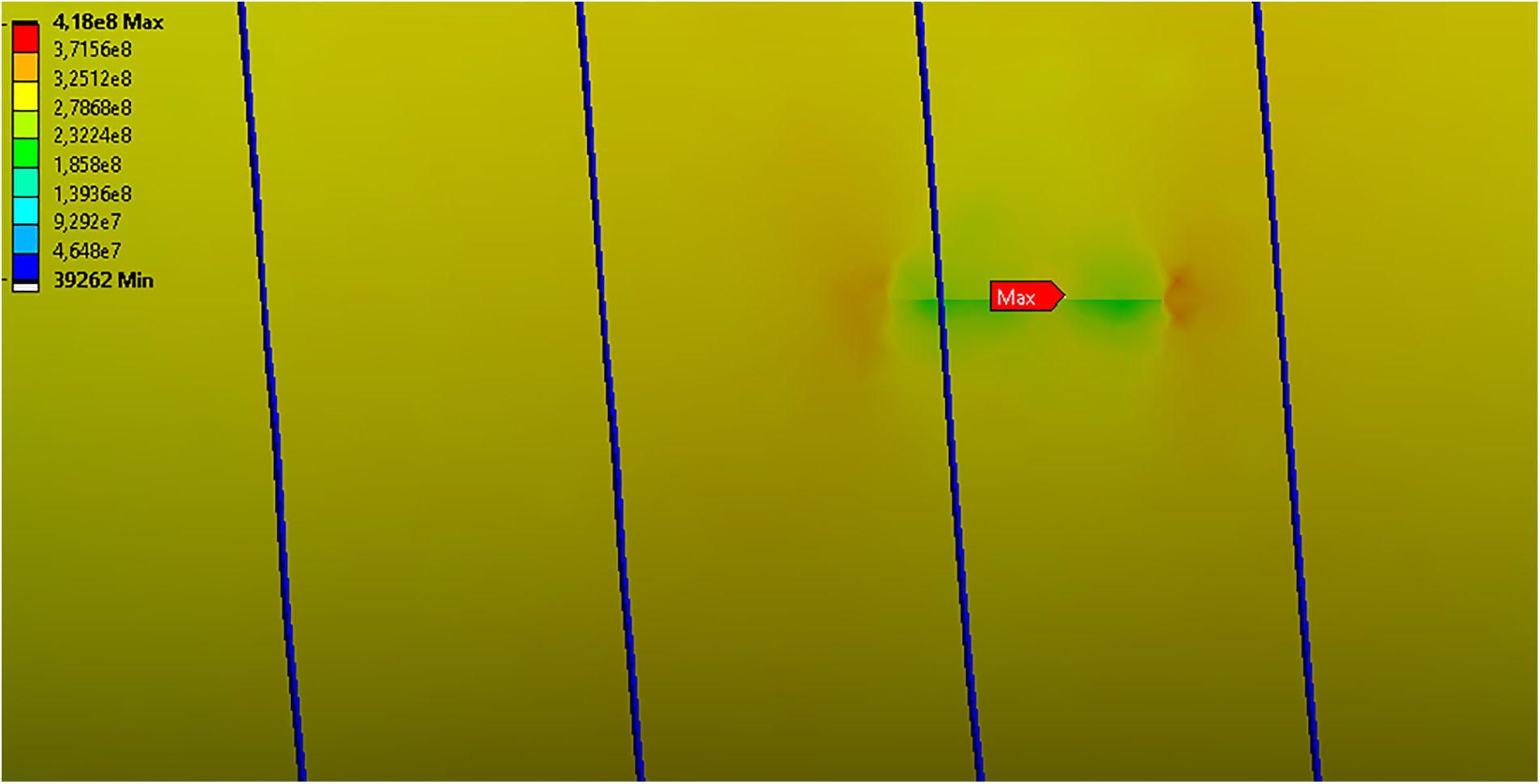
Figure 24: Stresses surrounding the crack area at
3.4 Analysis of the Temperature Effect on the Dynamics of the Wire Winding Reinforced Cross-Section of the Steel Gas Pipeline with a Non-Through Crack
The effect of temperature on the development of the non-through crack in the wire winding-reinforced cross-section of the steel pipeline was studied in this section. The winding had a pitch of 0.25 m and was made by a steel wire with a diameter d = 6.0 mm and stretched with a tensile force of 1.38 kN. These variables were chosen because the damaged pipeline cross-section retained its integrity at the operating pressure, and the non-through crack with a depth of half of the pipeline thickness did not develop into a through crack. Moreover, it did not lead to the avalanche fracture of the pipeline. The analysis showed that the critical pressure led to the pipeline fracture over the entire range of the temperature. Qualitatively, the obtained findings corresponded to the results above for a temperature of +20°C. The variations in the start and end coordinates of the crack along the Oz axis and in the length of the straight crack as a function of temperature are illustrated in Table 7. For the steel winding reinforced cross-section pipeline, the change in temperature within the established range led to insignificant variations in the crack length.

Similarly, the results obtained at the working pressure qualitatively corresponded to those at T = +20°C. For the whole considered temperature range, the integrity of the pipeline cross-section with a non-through crack was preserved. Figs. 25–27 show the stresses surrounding the crack area for the assumed range of temperature. In all cases, maximal stresses were observed in the central part of the crack. For the remaining parts of the pipeline, no critical stress localization was present. Particularly, a slight increment in the maximum stresses as the temperature dropped was observed. Consequently, the maximum stress at +50°C was 413 MPa, whilst the maximum stress at −40°C was 440 MPa. The obtained values were definitively lower than the elastic limits which, in turn, corresponded to the absence of plastic strains, thus leading to the pipeline fracture in the non-through crack area.
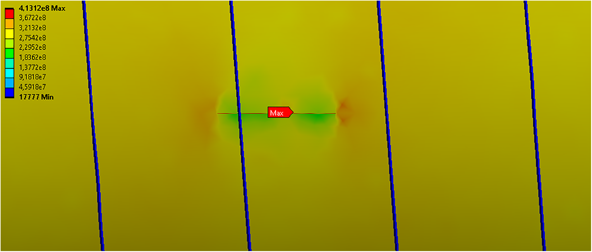
Figure 25: Stresses surrounding the crack area at
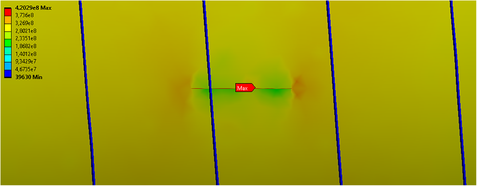
Figure 26: Stresses surrounding the crack area at
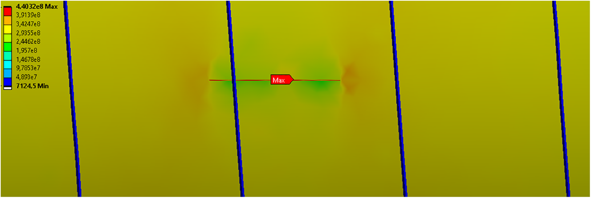
Figure 27: Stresses surrounding the crack area at
FE investigations of the large-diameter cross-section of the Beineu-Bozoy-Shymkent steel gas pipeline with a non-through straight crack, strengthened by a steel wire wrapping, were executed (Figs. 1–2). The numerical solution was implemented using the FE software package ANSYS-19.2/Explicit Dynamics, whilst the spatial discretization was based on the equation of motion [34,35]. The influence of the winding design parameters on crack propagation was analyzed considering the temperature effect on the pipeline material (Tables 1 and 2). Particularly, the influence of the tensile force applied to the steel wire winding filament was investigated (Table 3). The presence of the steel wire rings at the edges of the crack (at the initial stage of strain) restrained the crack opening and reduced its growth along the longitudinal direction (Figs. 4–6). However, the increase of the internal pressure within the pipeline cross-section until the critical values led to the formation of a through crack and opening of its edges. The opened edges pressed the steel wire and thus led to its rupture (Figs. 7–10). Therefore,
The influence of the diameter of the steel wire was also studied, showing that its increment from 4.0 mm to 6.0 mm (Table 5) led to the failure of the steel wire. The equivalent stresses over time are shown in Figs. 12–14. We noticed that such stresses increased by 32% from the beginning of the crack growth until the moment of the wire fracture. Furthermore, the increment in winding diameter slowed down the edge crack opening and led to a decrement in its length by 8.2% (Figs. 15–17). Consequently, the steel wire wrapping in the form of rings at the ends of non-through straight cracks prevented the avalanche failure of the steel pipeline at the operating pressure and reduced the length of crack propagation in its longitudinal direction at the critical pressure (Figs. 18–20). Regarding the influence of the winding pitch of the steel wire winding filament (Fig. 2), it was found that the decrement in the winding pitch led to a decrease in the maximum deformations in the pipeline cross-section (Fig. 21). Moreover, the critical load led to the formation of a through crack and its development in the longitudinal direction. Particularly, the winding led to a decrement in the crack length. Reducing the distance between the winding turns also led to a 33.6% reduction in the length of the straight crack (Table 6) and a 7.9% maximum stress decrease in the pipeline cross-section (Fig. 22). Under the working pressure, the crack remained non-through and, consequently, the pipeline cross-section did not fail (Figs. 23 and 24).
In conclusion, the temperature effect on the development of the non-through crack of the wire-wrapped hardened cross-section of the pipeline was studied within a temperature range of
A localization method for non-through straight cracks along steel gas pipelines by applying steel wire wrappings was considered in this study. Novel methodologies for selecting the wrapping parameters, e.g., the pitch between turns, the thread tensile force of the steel wire in the turn, and the thickness of the wire, were proposed. The methods were based on FE modeling of the structural integrity and failure of the wire-wrapped reinforced cross-section of the steel pipe with a crack. A refined nonlinear dynamic model of the pipeline’s stress-strain state was utilized for the FE modeling. It considered the effects of temperature on the mechanical characteristics, yield, and tensile limits of the steel pipe and wires. Also, the influence of the strain rate on the dynamic yield strength of the steel materials was considered. Moreover, the FE modeling assumed that the local failure of the steel materials was due to the large plastic deformations. The stress-strain state in the cross-section pipe, due to the thread tensile force of the wire, was simulated according to an accurate geometric model of the wire wrapping. The numerical studies yielded several practical results. According to the results of previous studies and the current work, the following conclusions were drawn regarding the prevention of crack propagation in steel gas pipelines considering the temperature effect:
1) Tensioning of steel pipelines by a single ring or wire windings was preferably carried out at the minimum value of the thread tensile force (
2) The increment of the steel winding diameter from 4.0 to 6.0 mm increased its destruction with time. The values of the equivalent stresses increased by 32% from the beginning of the crack growth until the moment of steel wire breaking. Also, the increase in winding diameter slowed down the edge crack opening and reduced its length by 8.2%.
3) Decreasing the winding pitch led to a decrease in the maximum deformations in the pipeline cross-section. Furthermore, decreasing the distance between the winding turns also led to a 33.6% decrease in the length of the straight crack and a 7.9% reduction in the maximum stresses in the reinforced pipeline cross-section (Fig. 22).
4) Considering the effect of temperature on the mechanical characteristics of the steel in the pipeline, the crack length varied by a maximum difference of 5.8% from
5) The analysis above concluded that the winding in steel gas pipelines significantly reduced the crack propagation length (up to 8.4 times), depending on the temperature effect and design parameters of prestressing.
Acknowledgement: As a result of this research, the authors obtained the following patent in the Republic of Kazakhstan: Method of localization and stopping avalanche destruction of main gas and pipelines; 2024, No. 9009 [44]. Authors would also like to thank the A. Pidhornyi Institute of Mechanical Engineering Problems of the National Academy of Sciences of Ukraine, and the National Science and Technology Council (NSTC) of Taiwan for providing advisory assistance to this work.
Funding Statement: This work was funded by the Science Committee of the Ministry of Science and Higher Education of the Republic of Kazakhstan (Grant No. AP19680589).
Author Contributions: The authors confirm contribution to the work as follows: Nurlan Zhangabay: Conceptualization, Data curation, Funding acquisition, Investigation, Methodology, Supervision, Writing original draft. Ulzhan Ibraimova: Conceptualization, Methodology, Writing original draft. Marco Bonopera: Conceptualization, Methodology, Writing—review & editing. Ulanbator Suleimenov: Data curation, Formal analysis, Supervision, Validation. Konstantin Avramov: Data curation, Resources. Maryna Chernobryvko: Investigation, Methodology, Writing original draft. Aigerim Yessengali: Formal analysis, Investigation. All authors reviewed the results and approved the final version of the manuscript.
Availability of Data and Materials: The data that support the findings of this work are available from the corresponding authors upon reasonable request.
Ethics Approval: Not applicable.
Conflicts of Interest: The authors declare that they have no conflicts of interest to report regarding the present study.
References
1. Mukashev A. The main newspaper of the oil capital Ak Zhaiyk. Available from: https://zonakz.net/2021/03/12/iznos-kazaxstanskix-gazoprovodov-sostavlyaet-bolee-70/. [Accessed 2024]. [Google Scholar]
2. Zhangabay N, Ibraimova U, Suleimenov U, Moldagaliyev A, Buganova S, Jumabayev A. Factors affecting extended avalanche destructions on long-distance gas pipe lines: review. Case Stud Constr. Mater. 2023;19(115):e02376. doi:10.1016/j.cscm.2023.e02376. [Google Scholar] [CrossRef]
3. Sultan N. Annual report of JSC Intergas Central Asia for 2019–2020. p. 78. Available from: https://intergas.kz/ru/reports/88. [Accessed 2024]. [Google Scholar]
4. Bolt R. Report for December 2020 on failures on gas pipelines in the period 1970–2019, carried out by the European Organization. Available from: https://www.egig.eu/reports. [Accessed 2024]. [Google Scholar]
5. Goodfellow GD, Haswell JV, Lyons CJ. Report for 2020 on pipeline failures carried out by the UKOPA organization in the period 1962–2020. Available from: https://www.ukopa.co.uk/published-documents/ukopa-reports/. [Accessed 2024]. [Google Scholar]
6. Farley A. A report of incidents over the past 20 years by the Pipeline Safety Organization (PHMSA). Available from: https://www.phmsa.dot.gov/data-and-statistics/pipeline/pipeline-incident-20-year-trends. [Accessed 2024]. [Google Scholar]
7. Kuvatov T. The official website of the information platform Kazakhstan today. Available from: https://www.kt.kz/rus/incidents/v_zko_v_rezuljtate_razriva_gazoprovoda_pogib_rabochij_1153537406.html. [Accessed 2023]. [Google Scholar]
8. By The Associated Press. The New York times information resource. Available from: https://www.nytimes.com/2006/12/27/world/africa/27nigeria.html. [Accessed 2023]. [Google Scholar]
9. Onion A, Sullivan M, Mullen M, Zapata CH. This Day In History Information Portal. Sewers explode in Guadalajara, Mexico, killing hundreds. Available from: https://www.history.com/this-day-in-history/sewers-explode-in-guadalajara. [Accessed 2023]. [Google Scholar]
10. Bassarova A. The gas pipeline collapsed on the territory of the ArcelorMittal Temirtau thermal power plant. Information Portal Kursiv. Available from: https://kz.kursiv.media/2023-01-18/lsbs-amt/. [Accessed 2023]. [Google Scholar]
11. Zardasti L, Yahaya N, Valipour A, Rashid ASA, Noor NM. Review on the identification of reputation loss indicators in an onshore pipeline explosion event. J Loss Prev Process Ind. 2017;48(4):71–86. doi:10.1016/j.jlp.2017.03.024. [Google Scholar] [CrossRef]
12. Onion A, Sullivan M, Mullen M, Zapata CH. This Day In History Information Portal. Natural gas explosion kills nearly 300 at Texas school. Available from: https://www.history.com/this-day-in-history/natural-gas-explosion-kills-schoolchildren-in-texas. [Accessed 2023]. [Google Scholar]
13. Gettleman J. Scores Dead in Kenyan Pipeline Fire. The New York Times. Available from: https://www.nytimes.com/2011/09/13/world/africa/13kenya.html. [Accessed 2023]. [Google Scholar]
14. Sui C. BBC News Information Portal. Available from: https://www.bbc.com/news/world-asia-28594693. [Accessed 2023]. [Google Scholar]
15. Ilincă C. Enhancing the integrity of a buried gas pipelines: investigating ruptures, explosions, and strengthening solutions. Eng Fail Anal. 2024;155:107738. doi:10.1016/j.engfailanal.2023.107738. [Google Scholar] [CrossRef]
16. Mahmood Y, Jessica Chen J, Nita Yodo N, Huang Y. Optimizing natural gas pipeline risk assessment using hybrid fuzzy bayesian networks and expert elicitation for effective decision-making strategies. Gas Sci Eng. 2024;125(22):205283. doi:10.1016/j.jgsce.2024.205283. [Google Scholar] [CrossRef]
17. Biagio M, Demofonti G, Mannucci G, Iob F, Spinelli CM, Schmidt T. Development of a reliable model for evaluating the ductile fracture propagation resistance for high grade steel pipelines. In: Proceedings of the 9th International Pipeline Conference, 2012; Calgary, Alberta, Canada; p. 24−8. doi:10.1115/IPC2012-90614 [Google Scholar] [CrossRef]
18. Ben M, Pluvinage G, Capelle J, Azari Z. Modelling crack propagation and arrest in gas pipes using CTOA criterion. Fracture at all Scales. 2016;21(4):171–94. doi:10.1007/978-3-319-32634-4_9. [Google Scholar] [CrossRef]
19. Yang F, Huo C, Luo J, Li H, Li Y. Crack Propagation and arrest simulation of X90 gas pipe. Int J of Pres Ves and Pip. 2017;149:120–31. doi:10.1016/j.ijpvp.2016.12.005. [Google Scholar] [CrossRef]
20. Zhang X, Lin M, Okodi A, Tan L, Leung JY, Adeeb S. Numerical analysis of API 5 L X42 and X52 vintage pipes with cracks in corrosion defects using extended finite element method. J of Pres Ves Tech. 2021;143(6):061302. doi:10.1115/1.4050988. [Google Scholar] [CrossRef]
21. Kaputkin DE, Arabey AB. Two types of the crack arrest during full-scale pneumatic testing of main gas pipelines. Lett Mater. 2021;11(3):239–43. doi:10.22226/2410-3535-2021-3-239-243. [Google Scholar] [CrossRef]
22. Kaputkin DE, Kaputkina LM, Abakumov AI, Esiev TS. Evaluation of energy parameters of fracture during drop weight tear tests based on the analysis of the geometry of the specimens. Lett Mater. 2020;10(3):340–4. doi:10.22226/2410-3535-2020-3-340-344. [Google Scholar] [CrossRef]
23. Shtremel’ MA, Arabei AB, Glebov AG, Abakumov AI, Esiev TS, Pyshmintsev IY. Dynamics of extended pipeline failure. Russ Metall. 2020;2020(10):1191–8. doi:10.1134/S0036029520100249. [Google Scholar] [CrossRef]
24. Altenbach H, Breslavsky D, Chernobryvko M, Senko A, Tatarinova O. Fast fracture of conic shell under the action of belt explosive charge. In: Altenbach H, et al. editors. Advances in mechanical and power engineering (CAMPE 2021). Cham: Springer; 2021. [Google Scholar]
25. Chernobryvko M, Kruszka L, Vorobiev Y. Thermo-elastic-plastic constitutive model for numerical analysis of metallic structures under local impulsive loadings. Appl Mech Mater. 2014;566:493–8. doi:10.4028/www.scientific.net/AMM.566.493. [Google Scholar] [CrossRef]
26. SP RK EN 1993-4-3-2007-2011 Design of steel structures. Part 4-3 Pipelines. Committee for Construction and Housing and Communal Services of the Republic of Kazakhstan, Asatan. 2016. Available from: https://online.zakon.kz/Document/?doc_id=34586480. [Accessed 2024]. [Google Scholar]
27. Sanitary rules of the Republic of Kazakhstan EN 1998-4. Seismic design. Part 4. Bunkers, reservoirs and pipelines. Astana; 2012. Available from: https://online.zakon.kz/Document/?doc_id=37105813&doc_id2=37807474#activate_doc=2&pos=1;-0.0999908447265625&pos2=3;-100.09999084472656. [Accessed 2024]. [Google Scholar]
28. SP 284.1325800.2016 Field pipelines for oil and gas. 2016. Available from: https://files.stroyinf.ru/Data2/1/4293742/4293742910.pdf. [Accessed 2024]. [Google Scholar]
29. API (American Petroleum Institute). API Specification 5L, 46th ed. Washington, DC, USA; 2018. Available from: https://buy-pipe.com/home/structure/item_214/955b42b7590d39be6f4d268afcd0a015.pdf. [Accessed 2024]. [Google Scholar]
30. Eurocode 8: Design of structures for earthquake resistance. Part 4: Silos, tanks, and pipelines. 2006. Available from: https://www.phd.eng.br/wp-content/uploads/2014/12/en.1998.4.2006.pdf. [Accessed 2024]. [Google Scholar]
31. Eurocode 3: Design of steel structures. Part 4: Silos, tanks, and pipelines. 2005. Available from: https://www.phd.eng.br/wp-content/uploads/2015/12/en.1993.1.8.2005-1.pdf. [Accessed 2024]. [Google Scholar]
32. ANSI/ASVE B 31G. Manual for determining the remaining strength of corroded pipelines. ASME, New York; 1984. Available from: https://law.resource.org/pub/us/cfr/ibr/002/asme.b31g.1991.pdf. [Accessed 2024]. [Google Scholar]
33. ANSI/ASVE B31.8-73 Gas transmission and distribution, piping systems. Available from: https://law.resource.org/pub/us/cfr/ibr/002/asme.b31.8.2003.pdf. [Accessed 2024]. [Google Scholar]
34. Zhangabay N, Ibraimova U, Bonopera M, Suleimenov U, Avramov K, Chernobryvko M, et al. Finite-element modeling of the dynamic behavior of a crack-like defect in an internally pressurized thin-walled steel cylinder. Appl Sci. 2024;14(5):1790. doi:10.3390/app14051790. [Google Scholar] [CrossRef]
35. Zhangabay N, Ibraimova U, Ainabekov A, Buganova S, Moldagaliev A. Finite-element modeling of the temperature effect on extended avalanche damage of gas main pipelines. Materials. 2024;17(9):1963. doi:10.3390/ma17091963. [Google Scholar] [PubMed] [CrossRef]
36. Zhangabay N, Tursunkululy T, Bonopera M, Azatkulov O. Laboratory investigation of the dynamic response of a prestressed composite steel cylindrical tank subjected to horizontal loading. J Compos Sci. 2023;7(9):373. doi:10.3390/jcs7090373. [Google Scholar] [CrossRef]
37. Zhangabay N, Bonopera M, Utelbayeva A, Tursunkululy T, Rakhimov M. Experimental and theoretical reproducibility research on the earthquake resistance of cylindrical steel tanks. Vibration. 2023;6(4):960–74. doi:10.3390/vibration6040057. [Google Scholar] [CrossRef]
38. Tursunkululy T, Zhangabay N, Suleimenov U, Abshenov K, Chernobryvko M, Utelbayeva A. Analysis of strength and eigenfrequencies of a steel vertical cylindrical tank without liquid, reinforced by a plain composite thread. Case Stud Constr Mater. 2023;18(116):e01776. doi:10.1016/j.cscm.2023.e02019. [Google Scholar] [CrossRef]
39. Tursunkululy T, Zhangabay N, Avramov K, Chernobryvko M, Suleimenov U, Utelbayeva A. Influence of the parameters of the pre-stressed winding on the oscillations of vertical cylindrical steel oil tanks. East-Eur J Enterp Technol. 2022;5(7):6–13. doi:10.15587/1729-4061.2022.265107. [Google Scholar] [CrossRef]
40. Martynenko G, Chernobryvko M, Avramov K, Martynenko V, Tonkonozhenko A, Kozharin V, et al. Numerical simulation of missile warhead operation. Adv in Eng Softw. 2018;123:93–103. doi:10.1016/j.advengsoft.2018.07.001. [Google Scholar] [CrossRef]
41. State standard 14959-2016. Metal products made of spring-spring non-alloy and alloy steel. Technical Conditions. 2016. p. 32. Available from: https://files.stroyinf.ru/Data2/1/4293747/4293747278.pdf. [Accessed 2024]. [Google Scholar]
42. Sorokin VG, Gervasyev MA. Steels and alloys. Vintage: Reference edition. Moscow: Publishing House: «Intermet Engineering»; 2001. p. 608. Available from: https://djvu.online/file/Elzj1ecA8fz4Z. [Accessed 2024] [Google Scholar]
43. Nordhagen HO, Kragset S, Berstad T, Morin A, Dørum C, Munkejord ST. A new coupled fluid-structure modelling methodology for running ductile fracture. Comput Struct. 2017;94-95(4):13–21. doi:10.1016/j.compstruc.2012.01.004. [Google Scholar] [CrossRef]
44. Patent of Republic of Kazakhstan. Method of localization and stopping avalanche destruction of main gas and pipelines. 2024. No. 9009. Available from: https://qazpatent.kz/ru. [Accessed 2024]. [Google Scholar]
Cite This Article
 Copyright © 2025 The Author(s). Published by Tech Science Press.
This work is licensed under a Creative Commons Attribution 4.0 International License , which permits unrestricted use, distribution, and reproduction in any medium, provided the original work is properly cited.


 Submit a Paper
 Propose a Special lssue
 View Full Text
 Download PDF
 Downloads
 Citation Tools