
 Submit a Paper
 Propose a Special lssue
 Open Access
ARTICLE

Quantitative Identification of Delamination Damage in Composite Structure Based on Distributed Optical Fiber Sensors and Model Updating
1 School of Materials Science and Engineering, Dalian University of Technology, Dalian, 116000, China
2 School of Mechanics and Aerospace Engineering, Dalian University of Technology, Dalian, 116000, China
3 Department of Civil Engineering and Natural Hazards, University of Natural Resources and Life Sciences, Vienna, 1180, Austria
4 Department of Engineering Mechanics, Hohai University, Nanjing, China
* Corresponding Author: Zhanjun Wu. Email:
(This article belongs to the Special Issue: Sensing Data Based Structural Health Monitoring in Engineering)
Structural Durability & Health Monitoring 2024, 18(6), 785-803. https://doi.org/10.32604/sdhm.2024.051393
Received 05 March 2024; Accepted 27 May 2024; Issue published 20 September 2024
 View Full Text
 Download PDF
Abstract
Delamination is a prevalent type of damage in composite laminate structures. Its accumulation degrades structural performance and threatens the safety and integrity of aircraft. This study presents a method for the quantitative identification of delamination identification in composite materials, leveraging distributed optical fiber sensors and a model updating approach. Initially, a numerical analysis is performed to establish a parameterized finite element model of the composite plate. Then, this model subsequently generates a database of strain responses corresponding to damage of varying sizes and locations. The radial basis function neural network surrogate model is then constructed based on the numerical simulation results and strain responses captured from the distributed fiber optic sensors. Finally, a multi-island genetic algorithm is employed for global optimization to identify the size and location of the damage. The efficacy of the proposed method is validated through numerical examples and experiment studies, examining the correlations between damage location, damage size, and strain responses. The findings confirm that the model updating technique, in conjunction with distributed fiber optic sensors, can precisely identify delamination in composite structures.Keywords
High-performance composite materials are widely used in the aerospace field due to their small specific gravity, large specific modulus, high specific strength, stable chemical properties, and fatigue resistance [1–3]. The use of composite materials in the project can achieve the purpose of reducing the weight of the aircraft structure and improving the structural performance. However, in the process of production and use of composite materials, damage will inevitably occur. Common composite damage includes matrix cracking, internal delamination, and fiber fracture [3,4]. The existence of damage will lead to a rapid decline in structural strength and seriously affect the structural performance of the aircraft. Therefore, it is of great significance to carry out damage identification and health detection of composite materials [5].
Currently, the commonly used damage identification methods include infrared detection, X-ray inspection, ultrasonic scanning inspection, laser speckle detection, etc. [6,7]. These traditional detection methods have high accuracy. However, they are seriously affected by the external environment, have a long maintenance cycle, and are unable to carry out real-time online damage quantitative monitoring. This paper focuses on the distributed fiber optic inspection technique for composite delamination damage detection. It is based on the principle that delamination leads to local discontinuities in structural stiffness characteristics, which affects the response value of the whole structure. Fiber optic sensors can realize the needs of composite materials when monitoring due to their small size, high-temperature resistance, and resistance to electromagnetic interference [8–10]. At present, many scholars have used fiber optic sensors for structural damage detection [11–13]. Liu et al. [14] used distributed fiber optics for damage identification of specimens with debonding and cracks to detect the health state of the bonded structure of thermal insulation. She verified that the damage identification method based on distributed fiber optic sensors can achieve damage identification of the structure. Chen et al. [15] demonstrated the feasibility of an automated damage identification method based on distributed fiber optics by using distributed fiber optics for the health inspection of aluminum alloy plates with prefabricated crack damage. Li et al. [16] proposed a method for the detection of structural damage based on the local strain characteristics of a composite plate by using distributed fiber optics to measure the in-plane strains. Califano et al. [6] developed a method for the detection of structural damage based on a distributed fiber optic sensor. distributed fiber optic sensors developed a passive health detection method to detect the presence or absence of damage in a composite plate by the change in strain. All of the above studies show that distributed optical fiber can achieve damage detection, however, it lacks in the precise location of damage very damage identification efficiency.
Damage detection in optical fibers can be considered as an optimization or minimization problem where the goal is to predict the response of the damage location model close enough to the measured response from the real structure [17]. The model correction technique is precisely the process of correcting the finite element model using the actual measured structural response values so that the response values of the corrected finite element model converge with the structure [18]. Damage identification can be performed based on the model correction technique, thus improving the efficiency of damage identification. There are existing model correction damage identification methods based on modal vibration patterns [19] and intrinsic frequencies [20]. Zhang et al. [21] proposed a structural damage identification method based on a 1-parameter regularization process founded on a modal-based finite element model correction method. Since a limited number of measured responses may not provide enough information to detect localized damage, Zhang et al. [22] utilized the reconstructed structural response for structural damage identification by combining the response reconstruction technique with a finite element model correction method based on response sensitivity. In addition to modal vibration patterns, Li et al. [23] proposed structural damage identification based on frequency response reconstruction and model correction, which provides a new idea for model correction. Although model correction techniques have been widely used, they have been studied mainly based on the dynamic response of modal vibration patterns in the past 20 years. The model correction technique is less studied in the hydrostatic response, and the structural dynamic test is more affected by noise in the actual structural inspection process. Therefore, static model correction has a better development prospect. In addition, a large number of actual measurement point data in the model correction process can correct results more accurately. The distributed fiber mentioned above has the feature of high density of measurement points, which can meet this requirement. The damage identification method based on model correction is based on the finite element method, which combines the finite element model data with the actual measurement data of the distributed optical fiber. The method utilizes the finite element model to overcome the computational difficulties brought by the complex structure to the damage identification method, and at the same time corrects the model structure with the measured strains, which solves the problem that the finite element model cannot accurately reflect the real state of the structure.
A major challenge with model-corrected composite damage identification methods is their significant computational cost. A large amount of finite element model data is required to perform model correction, and the optimization process typically generates tens of thousands of candidate solutions. Expensive finite element simulations need to be invoked for each candidate solution during the computational process. It becomes impractical to compute all possible solutions during the optimization process. To overcome this problem and to obtain accurate computational results in a reasonable time, it is proposed to replace the finite element model with a surrogate model. The surrogate model, also known as an approximation model, computes an approximation of the finite element model utilizing a function and uses its predicted values to guide the global search. Common methods of constructing surrogate models are the response surface method, radial basis function neural network method, artificial neural network model, and Kriging method [1,2]. The surrogate model can deal with nonlinear function problems and is now widely used in various research. Zhang et al. [24] proposed a method to assess the delamination damage of composites based on surrogate modeling. They detected the frequency change of the composite bending plate by vibration loading. Two intelligent algorithms, surrogate model and genetic algorithm, are used as inverse algorithms to predict the location and size of delamination. The finite element algorithm constructs database data for both algorithms during the calculation process. The results show that the two algorithms can predict composite delamination damage in a very reasonable way. Chen et al. [25] proposed an artificial neural network surrogate model to replace the finite element analysis used for the intrinsic frequency of composite beams. The artificial neural network is used to predict the intrinsic frequency of the composite plate and results with high accuracy are obtained. Zhang et al. [17] used the surrogate model in measured frequency data and proposed a frequency-based damage prediction method for composite delamination, which illustrated that the surrogate model can reduce the computational cost and improve the computational efficiency.
In this paper, a strain variation-based method for identifying delamination damage in prefabricated composite panels is proposed. The principle of the strain variation-based method is that the presence of delamination damage causes a strain shift and different sizes or damage locations will cause different variations. A finite element model of the composite plate is parametrically established, and the model is used to generate a database of prefabricated damage strains of different sizes and locations. A radial basis surrogate model is constructed using numerical simulation with distributed fiber-optic measurements of the strain response, and a global optimization solution using a multi-island genetic algorithm is used to determine the size and location of the prefabricated damage.
2.1 The Principle of Strain-Based Model Updating Damage Identification
In this study, the actual measured strain from damaged composite plate is taken as the reference, and the damage location and size in the finite element model are updated, until the simulated strain responses converge to the measured strains. This is essentially a constrained nonlinear optimization problem, which can be described by
The constraint conditions of the optimization problem are

Figure 1: Schematic diagram of correction parameters
Firstly, finite element simulations with different damage parameters were conducted according to optimal Latin cubic sampling. The obtained data was then used to train a radial basis function neural network (RBFNN) as a surrogate model representing the mapping relationships between the damage parameters (optimization variables) and the strain distributions. At last, the multi-island genetic algorithm was applied using the surrogate model to obtain the optimal solution, which corresponds to the real location and size of the damage. The model updating procedure is shown in Fig. 2.

Figure 2: Model correction flow chart
The core of the above damage identification method is the construction of a surrogate model. Surrogate model refers to, in the case of guaranteeing certain accuracy requirements to fit a function, the function of the calculation results and numerical analysis or physical test results close to the ideal mathematical model. Surrogate model has the characteristics of a short calculation cycle, small calculation volume, and high efficiency. Surrogate model mainly contains two parts: design of the experiment and the approximation method. First of all, through the design of the experiment in the space to select the sample point, the sample point is good or bad to determine whether the surrogate model is close to the actual response value. Then the response values at the sample points are obtained by analyzing software or physical test methods. Finally, a suitable approximate model is constructed with some of the sample points, and another part of the sample points is used to test the model for errors.
The commonly used sampling methods in the design of experimental are full factorial experimental design, partial factorial experimental design, central composite design, Latin cube sampling, orthogonal experimental design, uniform experimental design and so on.
Latin hypercube is a type of stratified random sampling that enables efficient sampling from the distribution space of variables. The advantage of this method is that it is computationally simple and operationally simple. The disadvantage is that it fails to take into account the homogeneity of the sampling. As a result, the sample points may not be uniformly distributed throughout the space leading to flaws in accuracy. In this paper the optimal Latin sampling method is used. The method is based on Latin cubic sampling with improvements in sample uniformity. It further improves the efficiency and accuracy of sampling by optimising the location of sampling points in space. Compared with Latin hypercubic, optimal Latin hypercubic can better deal with the high correlation between input variables and produce more reasonable samples, thus improving the accuracy of the simulation. Its basic principle is as follows: assuming that the number of test points is n and the number of design variables is m, the experimental design is n × m matrix
(1) The initial experimental design matrix is generated by random Latin hypercube design. The domain of definition of each design variable,
(2) Obtain the new experimental design matrix by element exchange operation.
(3) Calculate the space-filling optimality condition. Adopt the criterion of very large and very small distance:
(4) If the optimality condition is not satisfied, the improved stochastic evolutionary algorithm is used to search for the global optimal solution.
2.2.2 Radial Basis Function Neural Network
The Radial Basis Function Neural Network (RBFNN) consists of three layers: an input layer, a hidden layer and a output layer. The input layer node only transmits the input signal to the hidden layer. The hidden layer nodes are composed of radial action functions like Gaussian functions. Output layer nodes are usually simple linear functions. RBFNN is widely used because of its good flexibility and simple structure. For a radial bases function, the initial sample points
In the formula:
In the radial basis function, the commonly used radial functions are
Gauss function:
Multiquadric function:
Inverse multiquadric function:
where c is a given constant parameter greater than 0. Since these functions are positive definite in any space, the existence and uniqueness of
The radial functions chosen in this paper are Gaussian functions, which have the following advantages: (i) The representation is simple, which does not add much complexity even for multivariate inputs; (ii) Radial symmetry; (iii) Smoothness is good, and the derivatives of any order exist; (iv) Because of the simplicity of the function’s representation and analytical properties, it is easy to carry out theoretical analyses. The characteristics of the radial basis function model vary with the radial function used. When the radial basis function model uses the Gaussian function or the inverse multiquadric function as the basis function, the model will have the characteristics of local estimation due to the influence of the radial function. When the multiquadric function is used as the basis function, the model will have the characteristics of global estimation. The RBFNN is a surrogate model with good flexibility, simple structure, relatively small amount of calculation, and high efficiency.
In this study, data obtained from finite element simulations were used to train the RBFNN. The RBFNN as a surrogate model represents the relationship between the input damage parameters (optimization variables) and the output strain distributions. The surrogate model was then used by multi-island genetic algorithm to generate vast number of data for optimization.
2.2.3 Evaluation Method of Surrogate Model
The most commonly used evaluation indicators of the surrogate model are correlation coefficient and root mean square error.
(1) Correlation coefficient. It characterizes the degree of fit between the surrogate model and the original model.
(2) Root mean square error. It represents the error between the surrogate model and the original model.
2.3 Multi-Island Genetic Algorithm
Commonly used optimization algorithms include sequence planning method, moving gradient method, conjugate gradient method, surrogate model, simulated annealing method, particle swarm algorithm, genetic algorithm, and many other optimization methods. Genetic algorithm originated from the research of computer simulation of biological systems, which is a method of searching for the optimal solution to simulate natural selection and natural genetic process. Since the traditional genetic algorithm is easy to fall into the local optimal solution, scholars have improved the genetic algorithm by proposing a multi-island genetic algorithm (MIGA). MIGA has the ability of high computational efficiency and better global optimization and better overcomes the phenomenon of early convergence of the traditional genetic algorithm.
The essence of MIGA is a parallel genetic algorithm. In the optimization process, the population is divided into several islands, and genetic algorithms are performed on each island. In the process of genetic algorithm, the islands can be migrated, and the migration increases the diversity of the population. The individuals of the traditional genetic algorithm are divided into several subgroups, called ‘islands’, and the sub-groups on each island are subjected to independent genetic operations such as natural selection, mutation, and crossover. However, each island does not exist in isolation. Individuals between islands need to migrate, and individuals randomly selected on each island are regularly relocated to other islands. This migration process needs to be carried out quantitatively and regularly. The corresponding period refers to the migration period, which refers to the algebra that needs to be spaced between each migration. The migration operation makes the multi-island genetic algorithm maintain the diversity of the optimal solution, restrain the premature phenomenon, and improve the opportunity to contain the global optimal solution. The basic principle is shown in Fig. 3.

Figure 3: Multi-island genetic algorithm schematic diagram
The multi-island genetic algorithm first starts with the encoded initial population to determine the genetic individual. The algorithm produces a new generation of individuals through a combination of selection, mutation, and hybridization. Finally, the generations keep reproducing and evolving to continuously improve the population’s adaptability to the environment. According to the definition and principles of the multi-island genetic algorithm, the flowchart of the algorithm is made in Fig. 4.
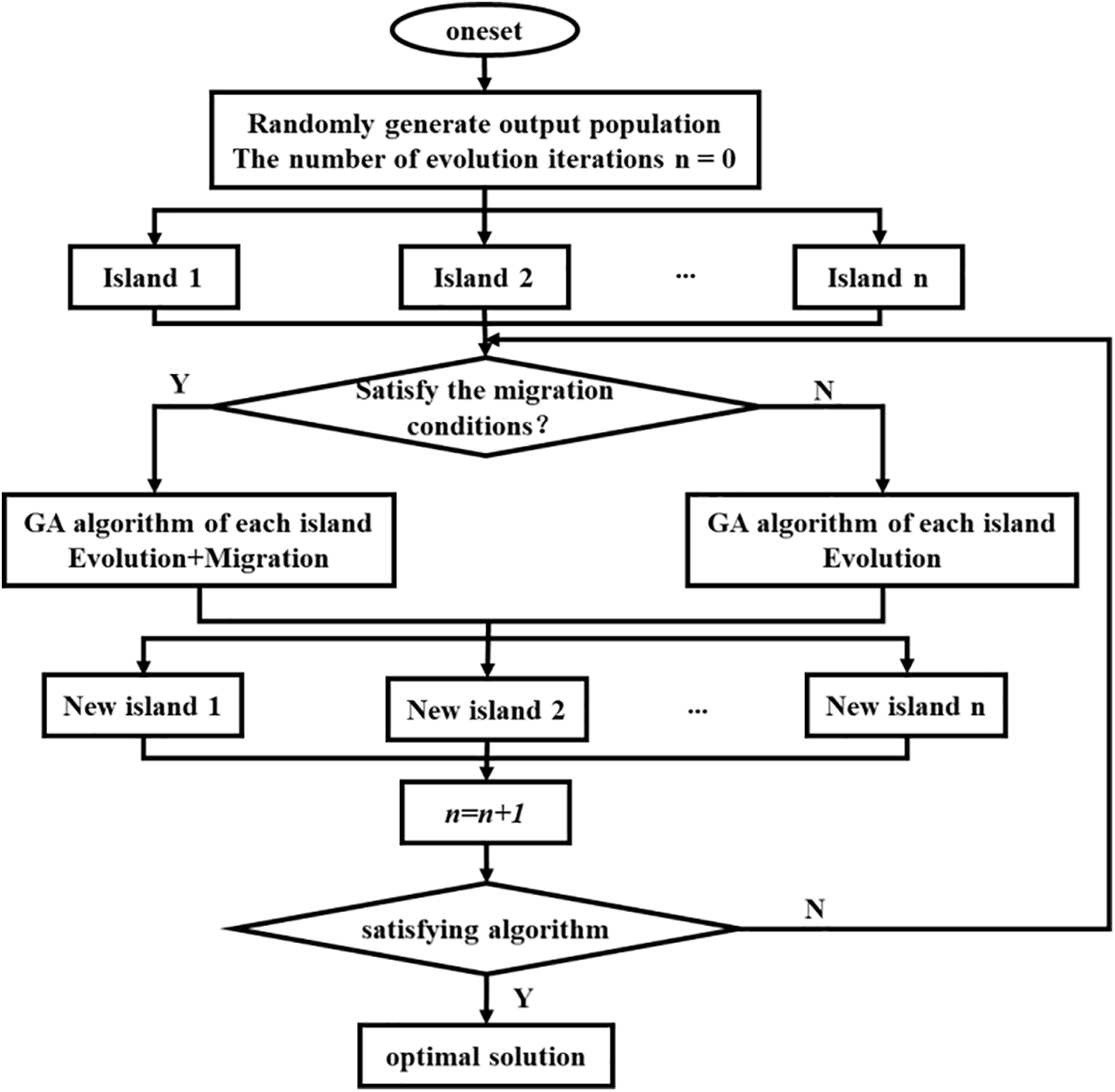
Figure 4: Multi-island genetic algorithm flow chart
2.4 Distributed Fiber Optic Measurement Principle
Optical fiber sensing technology is a technology that changes the propagation state (light intensity, polarization state, phase, etc.) of light in optical fiber through external factors, to detect external factors by demodulating optical signals. In optical fiber sensors, distributed optical fiber is a representative distributed optical fiber sensor based on Rayleigh backscattering. It demodulates the distributed optical fiber through the principle of optical frequency domain reflection. The optical fiber measurement system mainly includes an active detection unit. The active detection unit is connected to the passive detection fiber and emits a laser. Due to the uneven density of the optical fiber under the interference of different external factors, the refractive index of the light is different, and the reflection wavelength at this position will deviate. By comparing the changes of the reflected light before and after, the position and size of the deformation of the optical fiber can be demodulated. The Rayleigh scattering wavelength of light is affected by temperature and strain. The change of some properties of light can be treated as a function of strain/temperature on the fiber, so as to realize the measurement of strain and temperature.
In general, the change of temperature or strain will lead to the drift of the scattered light spectrum in the optical fiber. The spectral shift obtained by the strain
where
3 Damage Identification Simulation Verification Based on Model Updating
The correctness of the method is verified by numerical analysis. In this chapter, the strain data of the lossy model is mainly obtained through the finite element model as the reference value. The strain is equivalent to replace the strain data measured by the distributed optical fiber. Besides the strain value of the lossless finite element model is used as the correction data. Since the finite element simulation is used instead of the measured data, the effect of measurement error is avoided and the optimal result of the algorithm can be reflected. Nevertheless, the finite element simulation also ignores other states that may exist when the algorithm is applied, resulting in an over-accurate surrogate model that does not meet the practical application, which will be verified experimentally in the following. This chapter only discusses the ideal optimal solution.
The solid model was parametrically established using the finite element simulation software Abaqus. Due to the thinness of the composite plate, the mesh type uses a continuous shell cell with 8 nodes, which makes the calculation results more accurate. The basic dimensions of the simulated fiber-reinforced composite cantilever plate (Length: 200 mm, Width: 100 mm, Thickness: 3 mm). Each layer is 0.16 mm thick. A total of 18 layers are laid orthogonally, and the angle of the layers is 0°, 90°. In order to simulate the phenomenon of prefabricated delamination, the unit nodes connected above and below the debonding position are separated at the location of the damage when modeling to simulate the prefabricated damage. x, y is the location of the damage, z is the size of the damage, and the properties of the composite material are shown in Table 1.

The loading method is cantilever loading. Fixed constraint at the constraint site of the loaded end of the composite material and a distributed load perpendicular to the surface of the plate with a size of 10 N is applied at the free end of the other end. Assuming that the damage data of the damage model is x = 80 mm, y = 60 mm, z = 20 mm, the cloud diagram of the composite plate with damage is shown in Fig. 5. The strain on the 4 path nodes is extracted from the surface of the composite plate to facilitate the extraction of strain values. These nodes are used as collection points for the strain data, and this data is used as the data measured by the optical fiber.
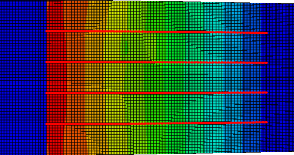
Figure 5: Finite element strain cloud diagram
From Fig. 6, it can be seen that under the cantilever loading condition, the strain law of the debonding area shows a central symmetrical distribution with two mutation peaks, and the location of the mutation is the location of the prefabricated damage.
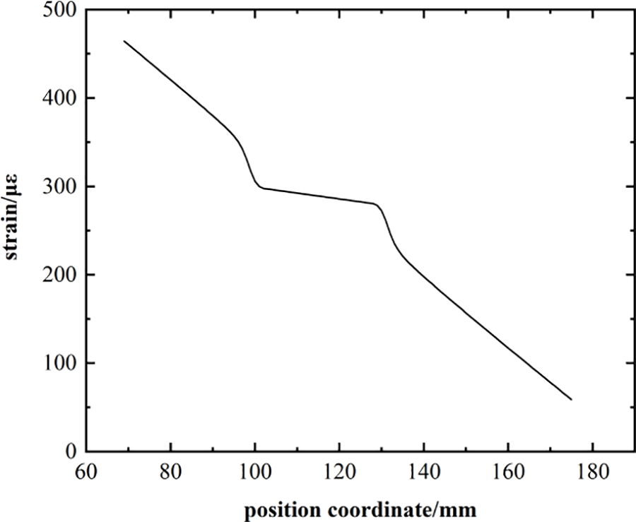
Figure 6: Strain distribution
Determine the optimization parameter range:
Two hundred and forty sets of samples were selected using optimal Latin hypercube and the response values of the corresponding samples were obtained by parameterizing the finite element model. Among them, 200 sets of data are used to fit the RBFNN surrogate model, and 40 sets of sample points are used for the error test of the surrogate model. The error test data of the surrogate model are shown in Fig. 7, and the error test values are shown in Table 2. The correlation coefficient R2, the root mean square error, the mean error, and the maximum error are all within the scope of the engineering license, indicating that the accuracy of the surrogate model is reliable. The maximum error between simulated and predicted values is 2.01%, which indicates that the prediction accuracy of the RBFNN surrogate model is good. Fig. 8a,b illustrates the three-dimensional functional surfaces of the objective function plotted against varying parameters. Specifically, Fig. 8a depicts the relationship between the damage size, the damage coordinate X, and the objective function, while Fig. 8b shows the correlation between the damage location coordinates X and Y, and the objective function.
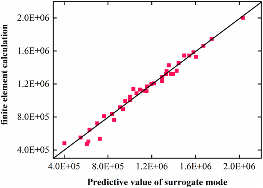
Figure 7: Surrogate model error test

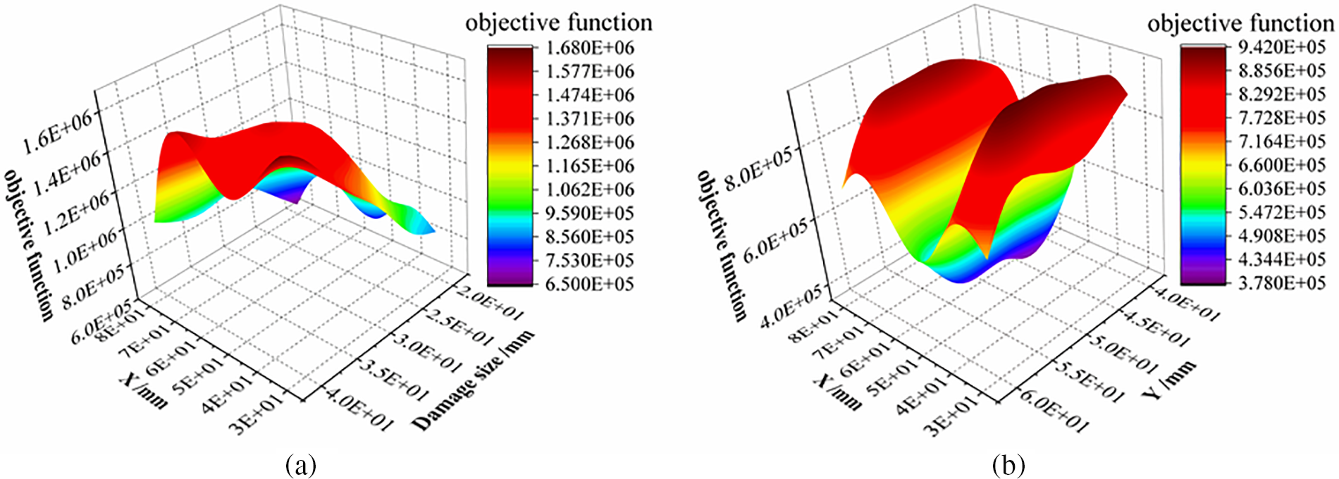
Figure 8: Surrogate model curve diagram
Multi-island genetic algorithm is a global search optimization method, suitable for solving complex nonlinear optimization problems. The RBFNN surrogate model can better fit the relationship between the size of the damage location and the objective function. Taking the range of values of the correction parameters as the constraints, the strain of the initial damage as the index, and the stochastic model with the minimum strain of the initial data as the objective function, the optimal solution is sought iteratively using the multi-island genetic algorithm.
To demonstrate the stability of the algorithm, the iteration curve for running 1000 iterations is shown in the figure. The algorithm for multi-island genetic is stable because it converges before the number of iterations reaches 1000 and the difference between the optimal and worst values is very small. The iteration process of the multi-island genetic algorithm is shown in Fig. 9.
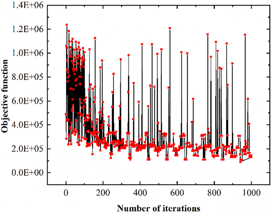
Figure 9: Optimization algorithm iterative process
The optimal solution is: x = 51 mm, y = 50 mm, z = 27 mm. The optimization objective is 136659.5. The optimization parameters are brought into the finite element model to verify the accuracy of the RBFNN surrogate model and the simulation result obtained is 142412.86. The actual result is compared with the prediction of the surrogate model and the error is 4.21%. From Fig. 10a, it can be seen that the strain trend of the model before correction is different from the initial model, while after correction as shown in Fig. 10b, the strain trend becomes almost the same. It shows that the RBFNN surrogate model is reliable and the damage identification method for composite structures based on the model modification is feasible.
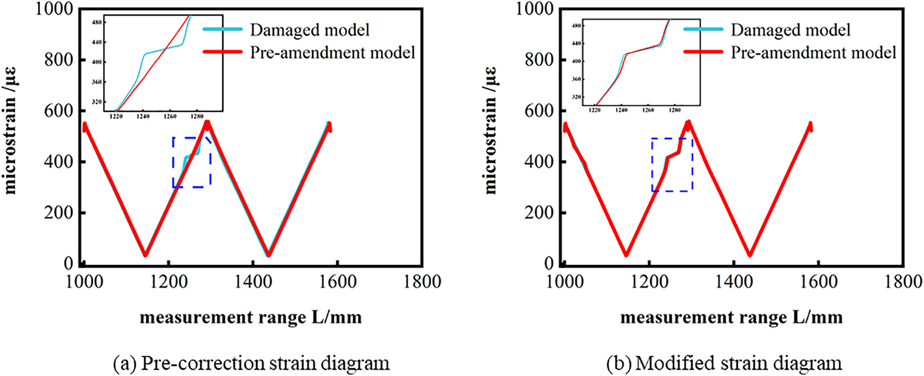
Figure 10: Strain comparison diagram before and after correction
4 Experimental Verification of Damage Identification Based on Model Updating
The methodology of composite structural damage identification based on model correction is verified to be feasible from the experimental point of view. The specimen is made of fiber-reinforced composite prepreg of T300, orthogonally laid, with 18 layers of 3 mm thickness. The composite properties are shown in Table 1. The size of the specimen is 194 mm × 100 mm. Besides, the length of the inspection area of the optical fiber is 110 mm, and the optical fiber is laid equidistant with a spacing of 20 mm, as shown in Fig. 11. The damage was prefabricated in the form of internally glued release cloth and the size of the damage was 30 mm × 30 mm.
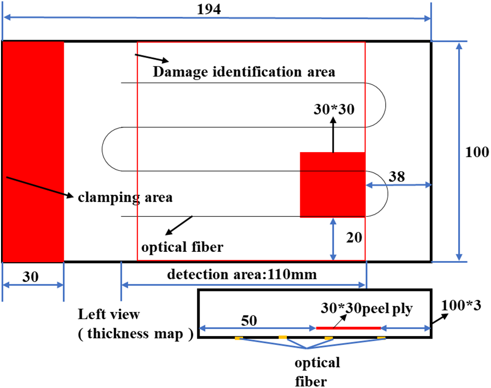
Figure 11: Optical fiber path layout diagram
The experiment was conducted in the form of cantilever loading as shown in Fig. 12. The specimen was placed on a clean horizontal table. After the fiber is connected to the device, the loading is carried out using suspended weights. One end of the specimen is fixed to the solid support end of the cantilever beam, and the other end of the fiber optic sensor is connected to the fiber optic demodulator, after the specimen is stabilized, the cantilever loading test is carried out. Distributed fiber optic signals were collected using the ODiSI distributed fiber optic collection signal from LUNA. Distributed fiber optic detection technology is a technology that uses external factors to make the propagation state of light in the optical fiber change, so as to monitor external factors by demodulating the optical signal. The unloaded state is taken as the initial state as the experimental benchmark, and the loading load is 7.5, 10.75, 20.75 N. The strain data of the specimen is collected after loading, and multiple measurements are taken to ensure the accuracy of the test. The strain trends obtained from the distributed optical fiber are shown in Fig. 13. It can be seen that the strain at the location of the second optical fiber has undergone a sudden change, indicating that the second optical fiber deployment passed through the upper surface of the prefabricated damage. Taking the location of the damage and the size of the damage as the optimization parameters, and the difference between the response value measured by the distributed fiber and the simulated response value as the objective function, the optimization problem can be formulated as follows:

Figure 12: Loading device diagram
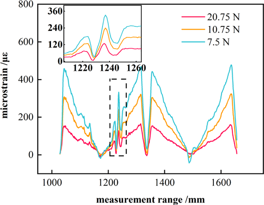
Figure 13: Test strain curve
The optimal Latin hypercube takes 360 sample points and parametrizes the finite element model for calculation. 300 groups of sample points are used to fit the surrogate model, and 60 groups of sample points are used for the error test. The error test data of the surrogate model are shown in Fig. 14, The error test values are shown in Table 3, in which the correlation coefficient R2, root mean square error, mean error, and maximum error are all within the scope of the engineering license indicating that the accuracy of the surrogate model is reliable.
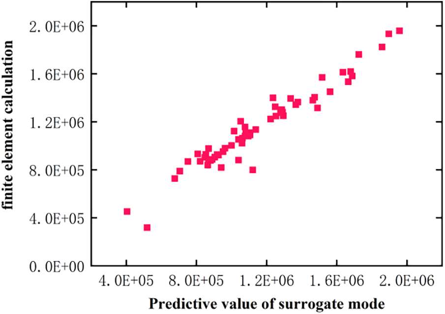
Figure 14: Error test

The initial number of populations in the optimization design is 10. the number of islands is set to 10. The total number of evolutionary generations is set to 50, and the whole optimization process requires 5000 iterations. Its optimization iteration process is shown in Fig. 15. It can be seen that in the whole optimization process, the objective function shows a decreasing trend, indicating that the algorithm has a good optimization function.
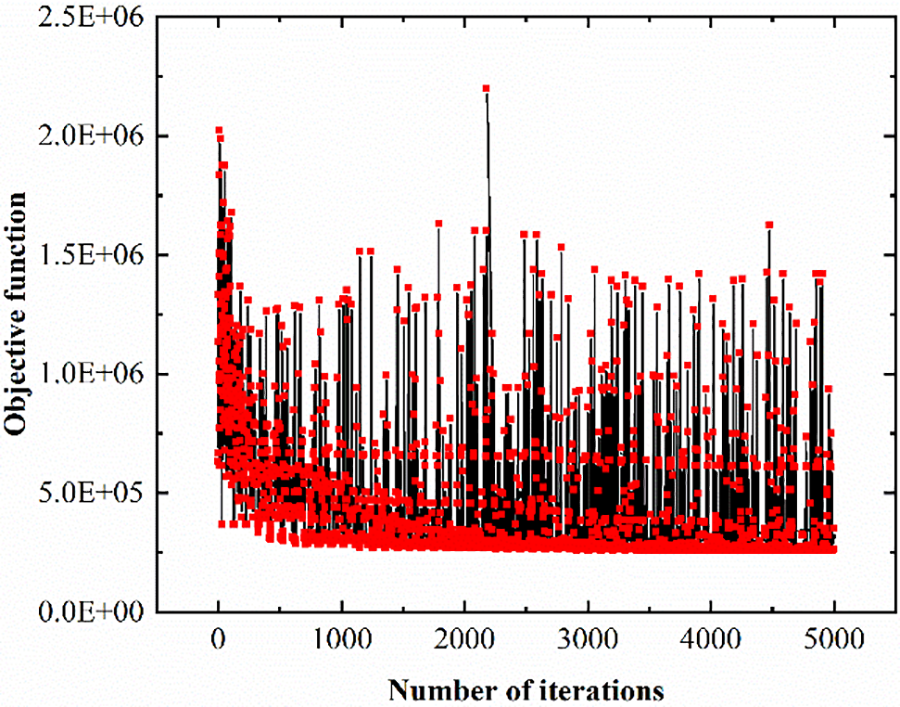
Figure 15: Optimization algorithm iterative process
If the finite element software exhaustive method is used directly to calculate all possible combinations within the range of design variables, totaling 176,715. During the calculation process, each model calculation takes 3 min and 30 s, totaling 10,308 h of calculation. However, using the RBFNN surrogate model requires only 350 sample points to be computed, which takes 17.5 h. The computational efficiency was improved by 99.83%, saving computational resources. The constructed RBFNN surrogate model approximation function is shown in shown in Fig. 16. In Fig. 16a, a three-dimensional functional surface is presented, depicting the relationship between the objective function and both the damage magnitude and the X coordinate of the damage location. Fig. 16b showcases a similar three-dimensional surface, but this time illustrating the connection between the objective function and the X and Y coordinates of the damage position.
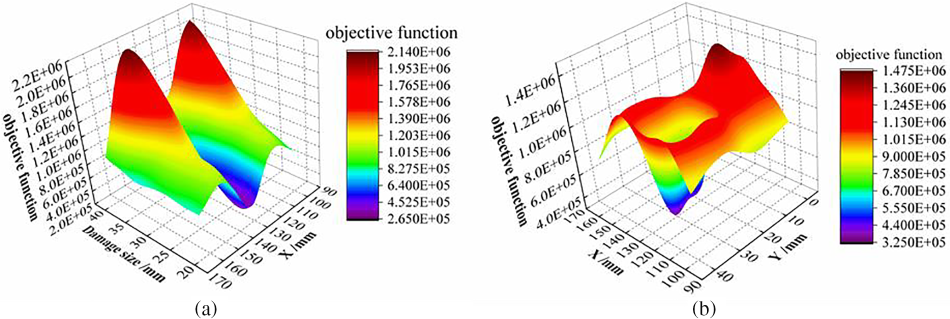
Figure 16: Surrogate model three-dimensional graph
Optimization is carried out on the surrogate model using a multi-island genetic algorithm with a total of 1000 iterations to calculate the optimal solution, the optimal solution and the initial values are shown in the table. The optimal solution is x = 126 mm, y = 23 mm, z = 30mm, and the comparison of damage identification results is shown in Table 4, in which the maximum error is 3.3%. The above data show that the damage identification method for composite materials based on strain model correction is feasible.

For the problem of composite material damage, damage detection can be achieved using various methods such as fiber optic sensors. Through the study, it was found that fiber optic sensing technology can only roughly locate the position of the damage, and can not accurately measure the size and location of the damage. The method has certain limitations. Therefore, this paper proposes a damage identification method based on model correction. Using the radial basis surrogate model and multi-island genetic algorithm, the size and location of prefabricated damage in composite plates are accurately characterized by the change of composite plate strain. A complete 3D model of the composite delamination plate was built using ABAQUS and strain measurements of the composite plate were carried out using distributed fiber optic sensors. The main conclusions of the study are as follows:
(1) Finite element simulation shows that if the deployed distributed optical fiber passes through the upper surface of the prefabricated damage, the strain at the location of the damage will undergo a sudden change. The sudden strain is characterized by a bimodal curve with larger values on both sides and smaller values in the middle.
(2) A high-precision approximation function is established based on the RBFNN surrogate model, which can replace the finite element simulation calculation. The method reduces the calculation time, saves the calculation cost, and improves the calculation efficiency.
(3) The study shows that the model correction method by combining the radial basis surrogate model with the multi-island genetic algorithm is feasible for damage identification. This approach can accurately locate the position of the damage, accurately predict the size of the damage, and the error of the damage localization is less than 3 mm, which provides a new method and idea for the damage identification of composite structures.
It should be pointed out that in engineering practice, damage would expand and exhibit complex shapes. In theory, if the damage expands, the strain oscillation region (e.g., in Fig. 13) will also expand, and the new damage region can be identified following the same process. However, the expansion shape would be complex so the optimization variables should be redesigned. Another issue is the speed of model updating, which should be addressed considering existing computational capability. Relevant studies will be reported in future work.
Acknowledgement: None.
Funding Statement: This work was supported by the National Natural Science Foundation of China (No. 12072056), the National Key Research and Development Program of China (No. 2018YFA0702800), the Jiangsu-Czech Bilateral Co-Funding R&D Project (No. BZ2023011), and the Fundamental Research Funds for the Central Universities (No. B220204002).
Author Contributions: The authors confirm contribution to the paper as follows: study conception and design: Hao Xu, Jing Wang, Zhanjun Wu; data collection: Jing Wang, Rubin Zhu, Alfred Strauss; analysis and interpretation of results: Hao Xu, Jing Wang, Rubin Zhu, Alfred Strauss, Maosen Cao; draft manuscript preparation: Zhanjun Wu, Maosen Cao. All authors reviewed the results and approved the final version of the manuscript.
Availability of Data and Materials: The authors confirm that the data supporting the findings of this study are available within the article.
Ethics Approval: Not applicable.
Conflicts of Interest: The authors declare that they have no conflicts of interest to report regarding the present study.
References
1. Mallik N, Wali AS, Kuri N. Damage location identification through neural network learning from optical fiber signal for structural health monitoring. In: Proceedings of the 5th International Conference on Mechatronics and Control Engineering, 2016; Venice, Italy. p. 157–61. doi:10.1145/3036932.3036937 [Google Scholar] [CrossRef]
2. Yan S, Zou X, Ilkhani M, Jones A. An efficient multiscale surrogate modeling framework for composite materials considering progressive damage based on artificial neural networks. Compos Part B: Eng. 2020;194:108014. doi:10.1016/j.compositesb.2020.108014. [Google Scholar] [CrossRef]
3. Wang X, Shi Q, Wang L, Lv Z, Chen X, Ma Y. Anisotropic reduction factor-based damage identification method for fiber-reinforced composite laminates. Struct Control Health Monit. 2018;25(11):2253. doi:10.1002/stc.2253. [Google Scholar] [CrossRef]
4. Agrawal S, Singh KK, Sarkar PK. Impact damage on fiber-reinforced polymer matrix composite–a review. J Compos Mater. 2014;48(3):317–32. [Google Scholar]
5. Sun G, Cai XH, Zhong WQ. Damage identification in composite plate using an inverse optimization procedure. Appl Mech Mater. 2012;166–169:3241–5. doi:10.4028/www.scientific.net/AMM.166-169.3241. [Google Scholar] [CrossRef]
6. Califano A, Chandarana N, Grassia L, D’Amore A, Soutis C. Damage detection in composites by artificial neural networks trained by using in situ distributed strains. Appl Compos Mater. 2020;27(5):657–71. doi:10.1007/s10443-020-09829-z. [Google Scholar] [CrossRef]
7. Chen XF, Yang ZB, Tian SH, Sun Y, Sun RB, Zuo H, et al. Prospects for damage identification and health monitoring of composite structures. J Vib Meas Diagn. 2018;38(1):1–10 (In Chinese). [Google Scholar]
8. Wang H, Guo JK, Mo H, Zhou X, Han Y. Fiber optic sensing technology and vision sensing technology for structural health monitoring. Sensors. 2023;23(9):4334. doi:10.3390/s23094334. [Google Scholar] [PubMed] [CrossRef]
9. Soman R, Wee J, Peters K. Optical fiber sensors for ultrasonic structural health monitoring: a review. Sensors. 2021;21(21):7345. doi:10.3390/s21217345. [Google Scholar] [PubMed] [CrossRef]
10. Glisic B, Inaudi D. Development of method for in-service crack detection based on distributed fiber optic sensors. Struct Health Monit. 2012;11(2):161–71. doi:10.1177/1475921711414233. [Google Scholar] [CrossRef]
11. Cheng L, Busca G, Roberto P, Vanali M, Cigada A. Damage detection based on strain transmissibility for beam structure by using distributed fiber optics. Struct Health Monit Damage Detect. 2017;7:27–40. doi:10.1007/978-3-319-54109-9_4. [Google Scholar] [CrossRef]
12. Zhang S, He J, Yu Q, Wu X. Multi-scale load identification system based on distributed optical fiber and local FBG-based vibration sensors. Optik. 2020;219:165159. doi:10.1016/j.ijleo.2020.165159. [Google Scholar] [CrossRef]
13. Shan Y, Xu H, Zhou Z, Yuan Z, Xu X, Wu Z. State sensing of composite structures with complex curved surface based on distributed optical fiber sensor. J Intell Mater Syst Struct. 2019;30(13):1951–68. doi:10.1177/1045389X19849287. [Google Scholar] [CrossRef]
14. Liu MJ, Xia ZX, Li JL, Wu ZJ, Gao DY. Research on damage detection of heat-insulating structure based on distributed optical fiber sensor. Piezoelectrics & Acoustooptics. 2020;42(6):765–8 (In Chinese). [Google Scholar]
15. Chen S, Huang N, Li JL, Zhang JQ, Li TT, Xu H, et al. Principal component analysis method for structural damage identification based on distributed optical fiber sensing signal. J Exp Mech. 2022;37(6):838–46 (In Chinese). [Google Scholar]
16. Li Y, Sharif-Khodaei Z. A novel damage detection method for carbon fibre reinforced polymer structures based on distributed strain measurements with fibre optical sensor. Mech Syst Signal Process. 2024;208:110954. doi:10.1016/j.ymssp.2023.110954. [Google Scholar] [CrossRef]
17. Zhang Z, Pan J, Luo W, Ramakrishnan KR, Singh HK. Vibration-based delamination detection in curved composite plates. Compos Part A: Appl Sci Manuf. 2019;119:261–74. doi:10.1016/j.compositesa.2019.02.002. [Google Scholar] [CrossRef]
18. Li J, Yu ZF, Chen SG, He SY, Chou H, Tang S. Study on structural model modification and load identification based on limited measuring points. Chin J Ship Res. 2023;18(5):57–64 (In Chinese). [Google Scholar]
19. Oh BK, Hwang JW, Choi SW, Kim Y, Cho T, Park HS. Dynamic displacements-based model updating with motion capture system. Struct Control Health Monit. 2017;24(4). doi:10.1002/stc.1904. [Google Scholar] [CrossRef]
20. Deng MY, Ren WX, Wang FM. Structure finite element model (FEM) updating based on static-load response surface methodology. J Exp Mech. 2008;3:42–5 (In Chinese). [Google Scholar]
21. Zhang C, Hong ZJ, Song GQ. Application of model updating method based on 1-norm regularization in structural damage identification. Chin J Appl Mech. 2013;30(5):756–61+807 (In Chinese). [Google Scholar]
22. Zhang CD, Xu YL. Structural damage identification via multi-type sensors and response reconstruction. Struct Health Monit. 2016;15(6):715–29. doi:10.1177/1475921716659787. [Google Scholar] [CrossRef]
23. Li J, Law SS, Ding Y. Substructure damage identification based on response reconstruction in frequency domain and model updating. Eng Struct. 2012;41:270–84. doi:10.1016/j.engstruct.2012.03.035. [Google Scholar] [CrossRef]
24. Chen HP, Le H, Kim J, Chattopadhyay A. Delamination detection problems using a combined genetic algorithm and neural network technique. In: 10th AIAA/ISSMO Multidisciplinary Analysis and Optimization Conference; 2004; Albany, NY, USA. p. 1098–111. [Google Scholar]
25. Zhang Z, He M, Liu A, Singh HK, Ramakrishnan KR, Hui D, et al. Vibration-based assessment of delaminations in FRP composite plates. Compos Part B: Eng. 2018;144:254–66. doi:10.1016/j.compositesb.2018.03.003. [Google Scholar] [CrossRef]
Cite This Article
 Copyright © 2024 The Author(s). Published by Tech Science Press.
This work is licensed under a Creative Commons Attribution 4.0 International License , which permits unrestricted use, distribution, and reproduction in any medium, provided the original work is properly cited.
 Downloads
 Citation Tools