
 Submit a Paper
 Propose a Special lssue
 Open Access
ARTICLE

Simulation and Traffic Safety Assessment of Heavy-Haul Railway Train-Bridge Coupling System under Earthquake Action
1 Engineering Research Center of Disaster Prevention and Mitigation of Southeast Coastal Engineering Structures (JDGC03), Fujian Province University, Putian, 351100, China
2 School of Civil Engineering and Architecture, Wuhan Institute of Technology, Wuhan, 430073, China
3 Hubei Provincial Engineering Research Center for Green Civil Engineering Materials and Structures, Wuhan, 430073, China
* Corresponding Author: Hongyin Yang. Email:
(This article belongs to the Special Issue: Health Monitoring and Rapid Evaluation of Infrastructures)
Structural Durability & Health Monitoring 2024, 18(6), 835-851. https://doi.org/10.32604/sdhm.2024.051125
Received 28 February 2024; Accepted 20 May 2024; Issue published 20 September 2024
 View Full Text
 Download PDF
Abstract
Aiming at the problem that it is difficult to obtain the explicit expression of the structural matrix in the traditional train-bridge coupling vibration analysis, a combined simulation system of train-bridge coupling system (TBCS) under earthquake (MAETB) is developed based on the cooperative work of MATLAB and ANSYS. The simulation system is used to analyze the dynamic parameters of the TBCS of a prestressed concrete continuous rigid frame bridge benchmark model of a heavy-haul railway. The influence of different driving speeds, seismic wave intensities, and traveling wave effects on the dynamic response of the TBCS under the actions of the earthquakes is discussed. The results show that the bridge displacement increase in magnitude in the lateral direction is more significant than in the vertical direction under the action of an earthquake. The traveling wave effect can significantly reduce the lateral response of the bridge, but it will significantly increase the train derailment coefficient. When the earthquake intensity exceeds 0.2 g, the partial derailment coefficient of the train has exceeded the limit value of the specification.Keywords
Heavy-haul railways, with their outstanding capacity, high efficiency, and economical cost, play an important role in the growth of national economies. However, they continue to suffer new technical problems. Located in the intersection area of the Circum-Pacific and Euro-Asian seismic belts, China experiences widely distributed seismic belts and frequent seismic activities [1]. Numerous bridges, both as-built and in-construction, are highly prone to earthquake-related damage [2]. The number of bridges is increasing, the span is increasing, and the operating environment is getting worse. Therefore, it is difficult to avoid a train operating on the bridge during or after the earthquake in both time and space [3,4]. It is imperative to thoroughly understand the principles of dynamic interaction and seismic response characteristics of heavy-haul railway train-bridge coupling systems (TBCS) under earthquake actions.
When an earthquake strikes, the passing train serves as a means of shock absorption and energy dissipation for the bridge structure. Due to the distinct natural vibration characteristics of the train and the bridge, a phase difference arises, thereby mitigating the response of the bridges [5]. Therefore, early studies perceived the train merely as an extra static mass rather than a dynamic system, potentially yielding conservative outcomes. At the same time, varying train speeds result in different positions of the train along the bridge, altering the vibration dynamics of the TBCS and impacting the vibration frequency and seismic response of both the bridge and the train body [6]. Tian and Lou [7] found that there is a significant difference between the bridge response considering the traveling wave effect and the uniform excitation, which has both positive and negative effects on the structure. Borjigin et al. [8] highlighted that earthquakes have a more significant impact on train response compared to track irregularities. Seismic excitation predominantly governs the vibration of the TBCS. However, disregarding the train load could result in an underestimation of the dynamic response of the structure. While analyzing the effects of earthquakes on bridges, the influence of train speed can be disregarded, but when assessing the impact of earthquakes on trains, train speed must be taken into account [9]. Ishida et al. [10,11] proposed an evaluation criterion that can ensure that the train does not derail at low speed. The mechanism of flange derailment that may occur when the train is operating at low speed is studied, and the creep characteristics are analyzed by train rolling test. Chen et al. [12] calculated and analyzed the traffic safety and resonance of small and medium-span bridges under different ground motions. The results show that the resonance of the system is related to the arrangement of loads, loading methods, bridge spans, and other factors.
Researchers have studied the seismic performance of bridge structures from the perspectives of different oblique incidence angles [13], different apparent wave velocities, and traveling wave effects caused by different phase differences. That is because the seismic response of the bridge structure is related to the dynamic characteristics of the ground motion and the structure, and the development of the seismic response analysis method is becoming more and more mature with the understanding of these two aspects. It is suggested that these effects should be fully considered in seismic analysis. On the basis of non-stationary random analysis, Jia et al. [14] established a new pseudo-excitation model, pointing out that the softer the site is, the greater the response of the rigid frame bridge will be, and the influence of the spatial heterogeneity of the site on the bridge will be greater. Shrestha et al. [15] believed that under the action of spatially varying ground motion, the longitudinal seismic response of the pier of the rigid frame bridge will decrease, but it will increase the relative displacement, collision force, and constraint deformation between the hinge joints of adjacent girders. Li et al. [16] conducted a study on the seismic response of a large rigid frame bridge and discovered that neglecting the site effect factor could lead to an underestimation of the structural response. Under complex terrain conditions, the side effect can markedly increase the ground motion of the bedrock. Therefore, an analysis method based on spatial correlation ground motion is proposed.
The seismic response of bridge structures is a very complex and dynamic process. From the initial calculation of the design to the actual construction period, the seismic numerical analysis or experimental study of the structure is required. Recently, numerous scholars have conducted shaking table tests on different bridge types. Lin et al. [17] conducted a comprehensive analysis of the fault crossing angle and subsidence process of a rigid frame bridge using a shaking table test. As for the cable-stayed bridge, Lin et al. [18] explored the damage process and the causes of the collapse of the bridge induced by strong vibration through shaking table tests. Furthermore, various scholars have delved into the seismic performance and vulnerability of bridges through numerical simulations. An et al. [19] identified two key factors influencing seismic response, ground motion and structural system. These factors have been found to have a profound impact on the overall performance and safety of bridges during seismic actions. Zheng et al. [20] carried out a vulnerability analysis of long-span suspension bridges during near-fault earthquakes, revealing the high influence of near-fault effects on the seismic performance of this bridge type.
Xia et al. [21] examined the dynamic response variation characteristics of the coupled system under varying apparent wave velocities and train speeds for the ground motion input mode. They identified the critical train speeds under different seismic intensities. Du et al. [22,23] performed a comparative analysis of two distinct ground motion input methods and found that, at the same integration step, the acceleration input method is preferable for the finite element method, while the displacement input method is better suited for modal analysis.
In the field of studying the TBCS under seismic action, scholars typically develop simulation programs to investigate dynamic issues of such systems by utilizing equations for train dynamics, bridge dynamics, and wheel-rail relationships. However, developing a dynamic simulation program for a TBCS under an earthquake often involves obtaining explicit expressions for parameters matrices (the mass, damping, and stiffness matrices) of large or complex bridge types like suspension bridges, cable-stayed bridges, arch bridges, and variable cross-section continuous rigid frame bridges. This self-developed simulation program may have disadvantages such as lengthy compilation times and challenging debugging processes. At the same time, to meet the applicable conditions of the simulation program, it is usually necessary to simplify some specific problems, which may lead to distortion of the simulation results.
This article presents a dynamic equation solution method for the earthquake-TBCS using the collaborative work of MATLAB and ANSYS (MAETB). Providing a new idea for studying the dynamic problems related to the TBCS. By leveraging MATLAB to call the general software ANSYS, the dynamic response of the bridge under a specified time-range external load is calculated, and the coupling system dynamic responses are determined using the whole process iterative method. Avoiding the need to obtain explicit expressions of parameter matrices of large or complex bridge types, the computational difficulty can be greatly reduced by the MAETB. The simulation system is utilized to analyze the dynamic parameters of a heavy-haul railway bridge. This study examines the impacts of different driving speeds, seismic wave intensities, and traveling wave effects on the dynamic response of the TBCS under earthquake actions.
2 Train-Bridge Coupling Vibration Calculation under Earthquake Action
2.1 Vibration Equations of the TBCS under Earthquake
The traditional bridge seismic analysis concentrated primarily on the relative motion of the structure, with less consideration given to the effect of the quasi-static term. However, in the vibration analysis of the TBCS under earthquake, the absolute motion of the system must be considered, which requires more attention to the effect of quasi-static terms. The x-axis, y-axis, and z-axis of the coordinate system are represented by the longitudinal, transverse, and vertical coordinates of the bridge, respectively, and the absolute coordinate system satisfies the right-hand criterion. Assuming that the ground motion varies non-uniformly at each support point of the bridge, the resulting vibration equations for the train and bridge systems are formulated as follows:
where M, C, and K are mass, damping, and stiffness, respectively; u is displacement; the subscripts s and b represent the non-support point and support point of the structure, respectively; and the subscripts V and B represent the train and bridge system, respectively. The relationship between
In the absolute coordinate system, the first term in Eq. (2) is expanded, and the equation of bridge motion is derived, that is:
The
When the relationship between the wheel and track is linear, it can be used as a function of the motion state between the train and the bridge subsystem, and the bridge dynamic response is decomposed by quasi-static displacement to make it convenient for seismic analysis.
Among them, the superscript s and d represent the quasi-static and dynamic terms of the bridge, respectively; Assuming that
Among them, the superscripts S and D represent the part of the TBCS dynamic interaction that is only related to the quasi-static term of the bridge and the part related to the dynamic term of the bridge, respectively.
The dynamic interaction caused by the quasi-static term of the bridge is elucidated using the assumption of wheel-rail vertical adhesion and the Kalker creep theory. The wheel-rail displacement resulting from the quasi-static displacement of the bridge can be determined through the subsequent formula:
Among them,
The additional quasi-static effect of the bridge has a wide range of influence, and the forces or moments acting on the transverse, vertical, and torsional directions of the bridge are:
The forces acting on the yaw, heave, roll, nod and yaw directions of the train bogies are:
Generally speaking, the motion equations of the TBCS under earthquake action are often solved by the method of separation iteration [26]. However, it is known from Eqs. (6) and (7) that when calculating the dynamic response of large or complex bridge types, the specific values of its parameter matrices must be obtained, which is a very challenging task. There is a significant demand to explore novel approaches that can mitigate the computational complexity associated with analyzing the responses of the TBCS under earthquake actions.
2.2 Solving Method Based on the MAETB
Employing widely-used general-purpose software ANSYS to compute the bridge dynamic response subjected to the prescribed time interval external load is feasible. Leveraging the collaborative work of ANSYS and MATLAB, the whole process iteration method is employed to address Eqs. (6) and (7) [27], culminating in the compilation of the joint simulation program (MAETB) for the TBCS under seismic actions. Fig. 1 shows the flow chart detailing the MAETB. The computational procedure can be expressed as follows:
Step 1: Consider the bridge as a rigid system, where seismic effects can be treated as overall translational motion. Superimpose the motion of the bridge deck and irregularities as external forces. Utilize MATLAB software to solve and export the dynamic forces acting on each wheel of the train system at the nth time step.
Step 2: Utilize MATLAB to call ANSYS and superimpose the dynamic time histories obtained from Step 1 onto the bridge deck. Apply seismic loads using the displacement method. Then, utilize ANSYS to compute and export the bridge deck dynamic response at the nth time step.
Step 3: Combine the bridge deck time histories obtained from Step 2 with the corresponding irregularities as external forces. Use MATLAB to solve and export the dynamic forces acting on each wheel of the train system at the (n + 1) th time step.
Step 4: Calculate the difference between the dynamic force histories of the wheels at time steps n + 1 and n. If this difference meets the desired computational accuracy, stop the computation. Otherwise, repeat Steps 2 through 4.
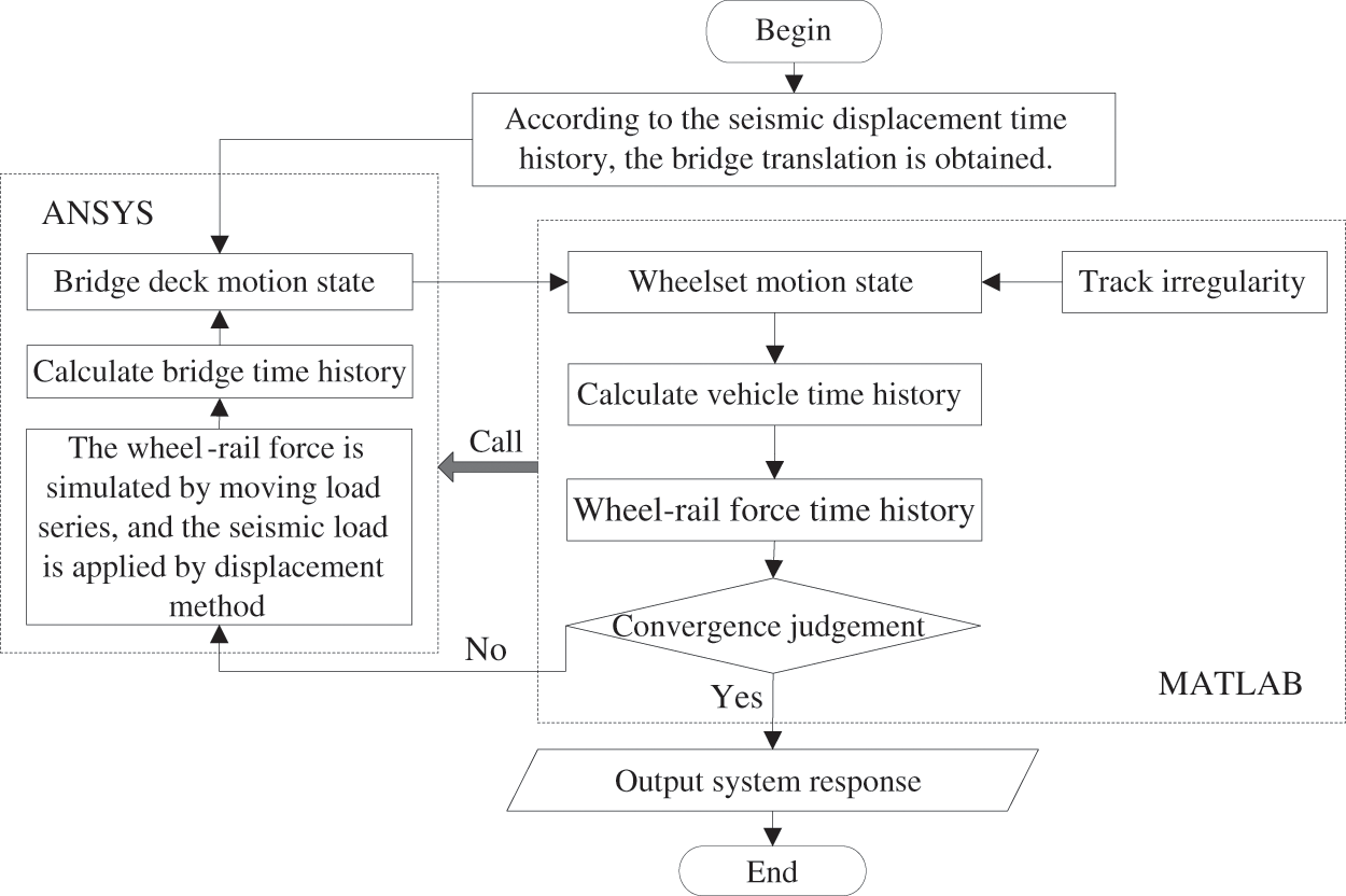
Figure 1: Flow chart of the MAETB
To validate the reliability of the MAETB, the examples cited in reference [24] have been chosen for comparative analysis, in this example, eight trains are grouped and operated at a speed of 250 km/h on a typical railway simply supported beam bridge featuring 10 spans and 32 m. The whole process dynamic response of the TBCS is computed, assuming that the first section of the train arrives on the bridge immediately following the earthquake. The irregularity sample is simulated based on the German PSD, and the seismic wave selects the El-Centro wave as the external input. Considering both vertical and lateral seismic excitations, the peak values of lateral and vertical seismic waves are standardized by 1 and 0.5 m/s2, respectively. The acceleration and displacement samples are shown in Fig. 2. Detailed parameters of bridges, trains, and earthquakes are shown in reference [24].
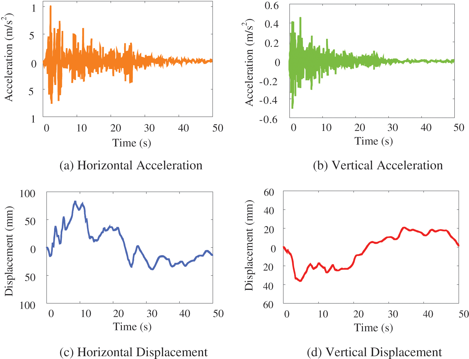
Figure 2: Time history curve of the El-Centro wave
In Figs. 3 and 4, the vibration responses of the first train body and the mid-span of the bridge are given respectively. It is clear that the numerical simulation results of this article and reference [24] are in good agreement, and the trend and amplitude of the response are in good agreement. It must be pointed out that because the time domain data of irregularity in reference [24] are different from those in this article, and the model in this article does not consider the track deformation, the vertical and lateral accelerations of the train are slightly different, but they are generally close, indicating that the MAETB method is reliable.
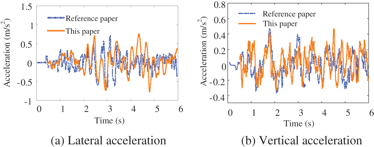
Figure 3: Vibration acceleration of the first train body under earthquake action
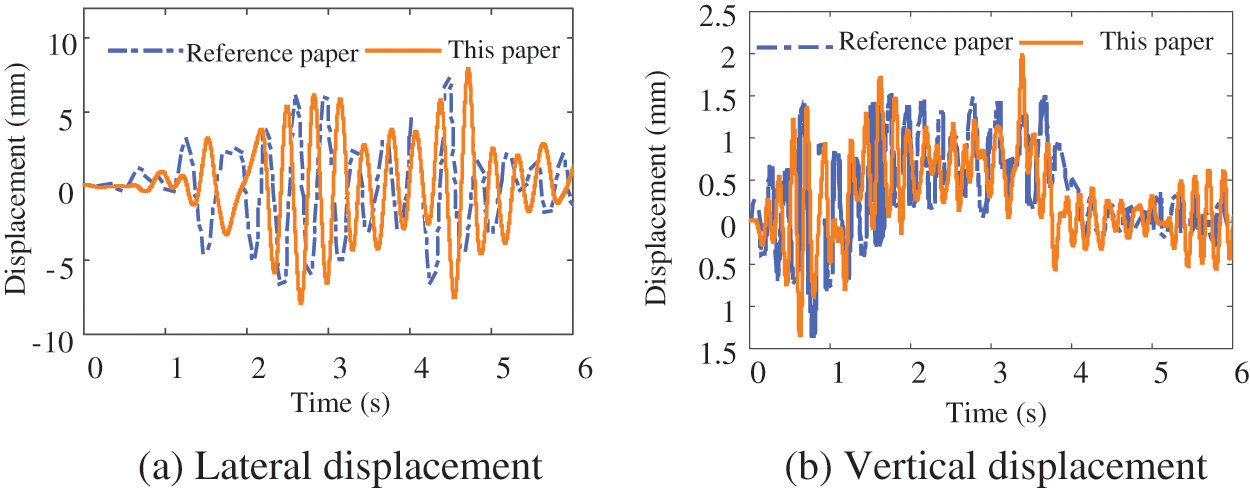
Figure 4: Vibration displacement of bridge mid-span under earthquake action
4 Engineering Example Analysis
The main bridge of a heavy-haul railway bridge consists of a three-span prestressed concrete continuous rigid frame bridge with span lengths of 96, 132, and 96 m. The outline of the bridge is shown in Fig. 5. The main beams are of variable cross-section and are equipped with prestressed systems in three directions: longitudinal, transverse, and vertical. The rigid abutment piers use rectangular hollow piers with a variable width in the transverse direction. The bridge abutments and rigid piers are founded on drilled pile foundations, with the pile tip penetrating through cavities and embedded to a certain depth in stable bedrock. The layout of the main girder bridge spans and the cross-section form of the beam are shown in Figs. 6 and 7, respectively.
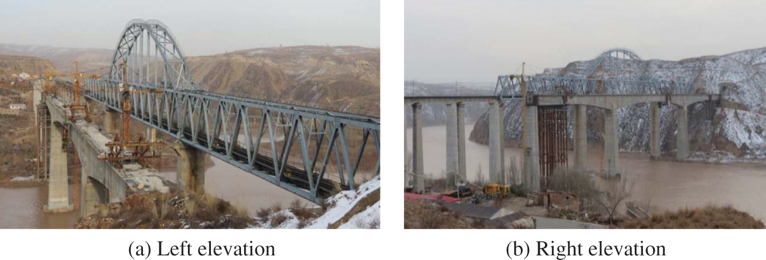
Figure 5: Overview of the main bridge of a super large bridge
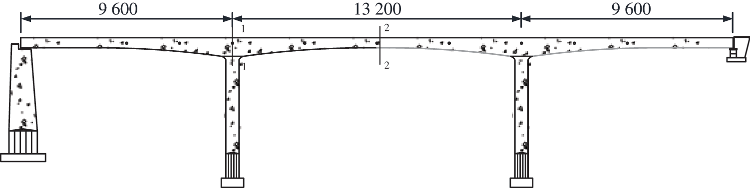
Figure 6: Bridge facade map (unit: cm)
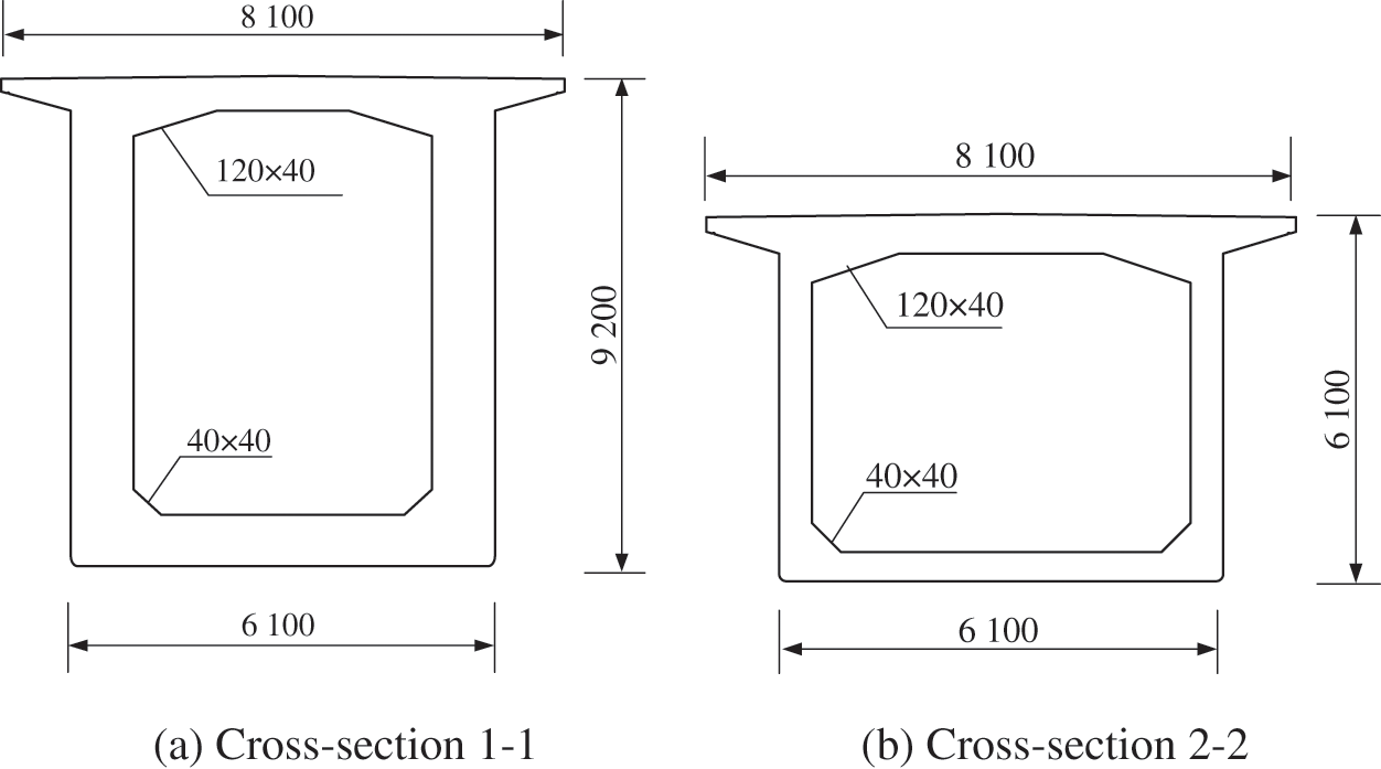
Figure 7: Bridge section diagram (unit: mm)
In the analysis of the response of the TBCS under earthquake actions, a combination of horizontal Ex and vertical 0.5 Ex earthquake excitations is employed to comprehensively account for the seismic effects. It is noted that the forms of acceleration in both the horizontal and vertical directions are identical [28].
4.1 The Influence of Earthquake Action on the Response of the TBCS
It is assumed that the first train arrives on the bridge immediately following the earthquake. The influence of earthquake action on the TBCS is discussed. Twenty-five heavy-haul trains are grouped for calculation. The time history curve of the bridge mid-span vibration response under an earthquake action is shown in Fig. 8. As shown in Fig. 8, the magnitude of various bridge vibration responses under earthquake action is significantly increased compared with that without considering earthquake action. Without considering the seismic action, the vertical bridge displacement is primarily caused by the gravity of the train, and the transverse direction is only affected by irregularity. Compared with the vertical displacement, the lateral bridge displacement is smaller. However, in the event of an earthquake, the increase in displacement in the vertical direction is much smaller than the increase in the lateral direction.
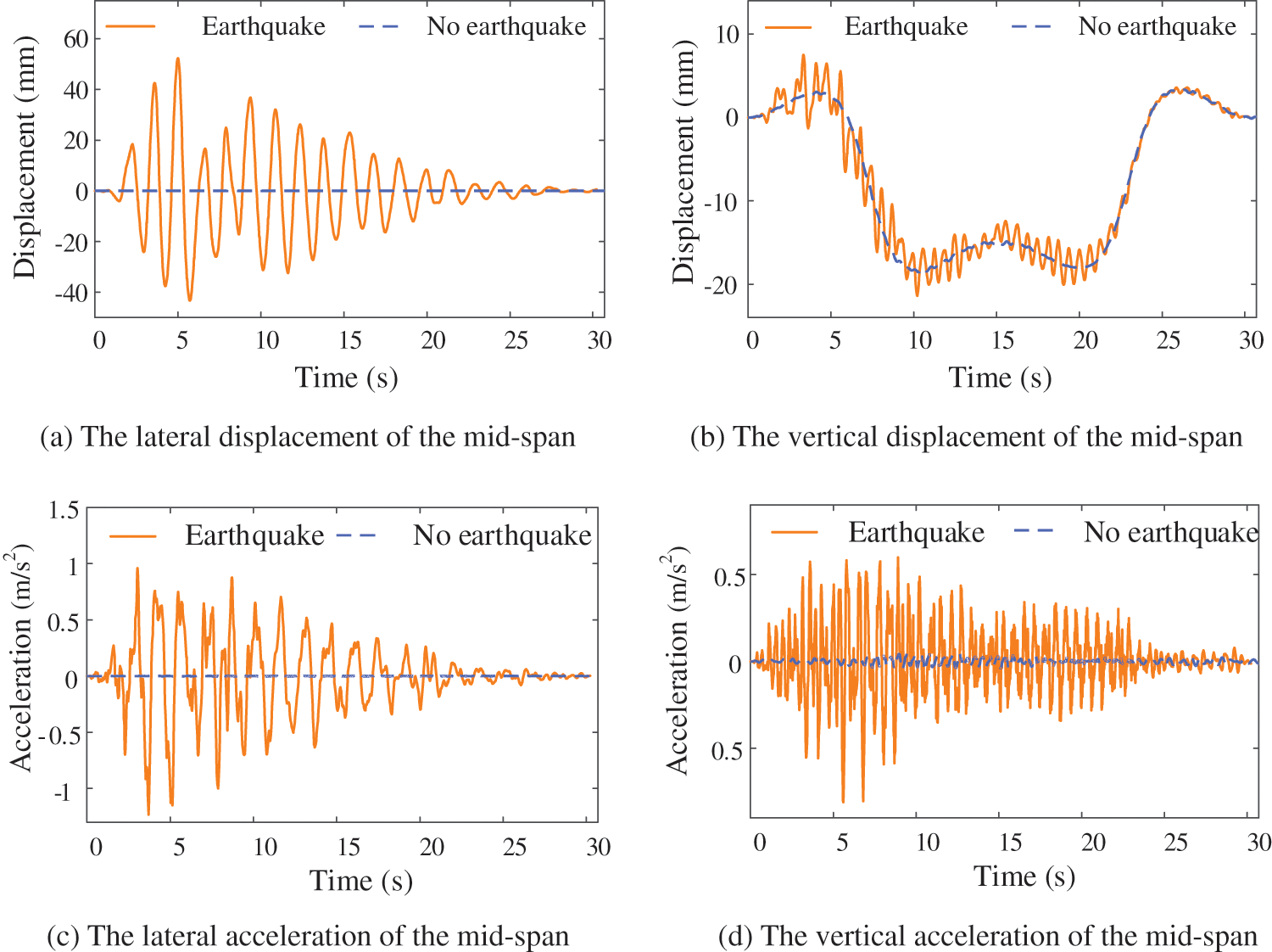
Figure 8: The influence of earthquake action on the dynamic response of the bridge system
Similarly, as shown in Fig. 9, the acceleration of the train under an earthquake is also quite different from that without an earthquake. In the event of an earthquake, the changes in lateral and vertical acceleration of the train body are quite noticeable. Moreover, the derailment coefficient and wheel load reduction rate are significantly improved, indicating that the earthquake action reduces the safety of train drives.
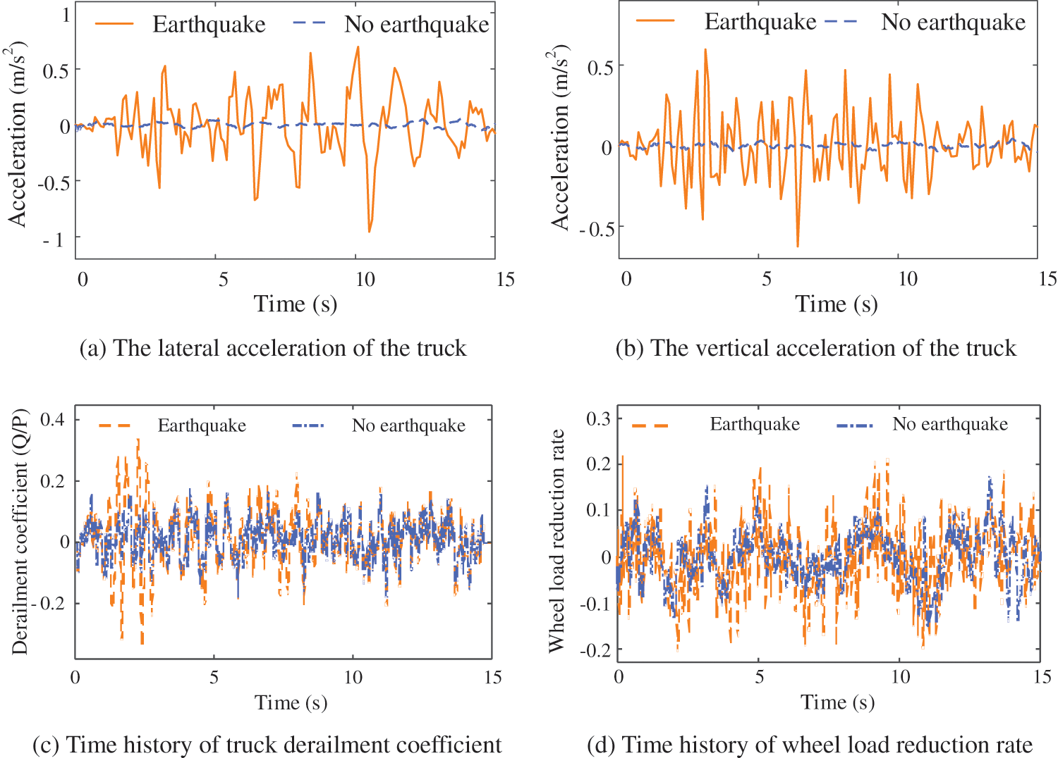
Figure 9: The influence of earthquake action on the dynamic response of the train system
4.2 The Influence of the Traveling Wave Effect on the Response of the TBCS
To study the dynamic interaction law of the whole system under the traveling wave effect, the traveling wave velocity of 500 m/s is used and compared with the uniform seismic transmission. When the train is operating at a speed of 60 km/h, the vibration time history of the bridge mid-span and the first train body are shown in Figs. 10 and 11, respectively.
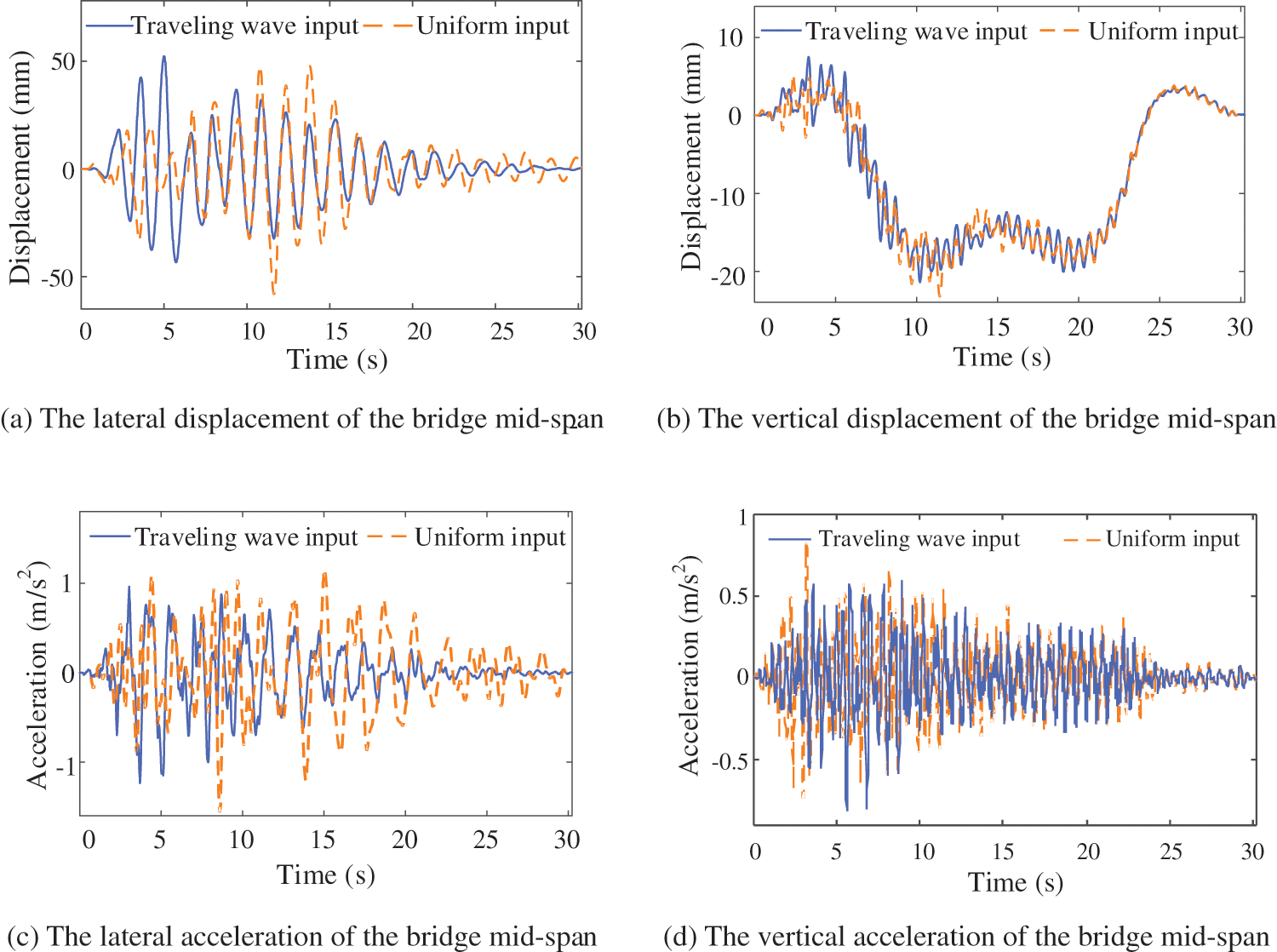
Figure 10: The influence of seismic traveling wave effect on the dynamic response of bridge system
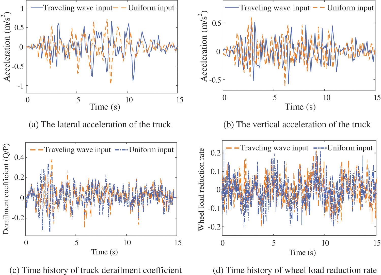
Figure 11: The influence of seismic traveling wave effect on the dynamic response of train system
Fig. 10 shows that the seismic traveling wave effect significantly changes the peak value and occurrence time of the bridge vibration response, which is consistent with the seismic input. The results are significantly different from those of uniform input. In particular, the traveling wave effect can significantly reduce the lateral response of the bridge.
Similarly, Fig. 11 shows that the traveling wave effect obviously changes the peak time of the train body vibration response, derailment coefficient, and wheel load reduction rate, but the overall peak value is relatively close. The relationship between the peak bridge vibration response at the mid-span and the train speed under the two conditions of uniform input and traveling wave input is shown in Fig. 12.
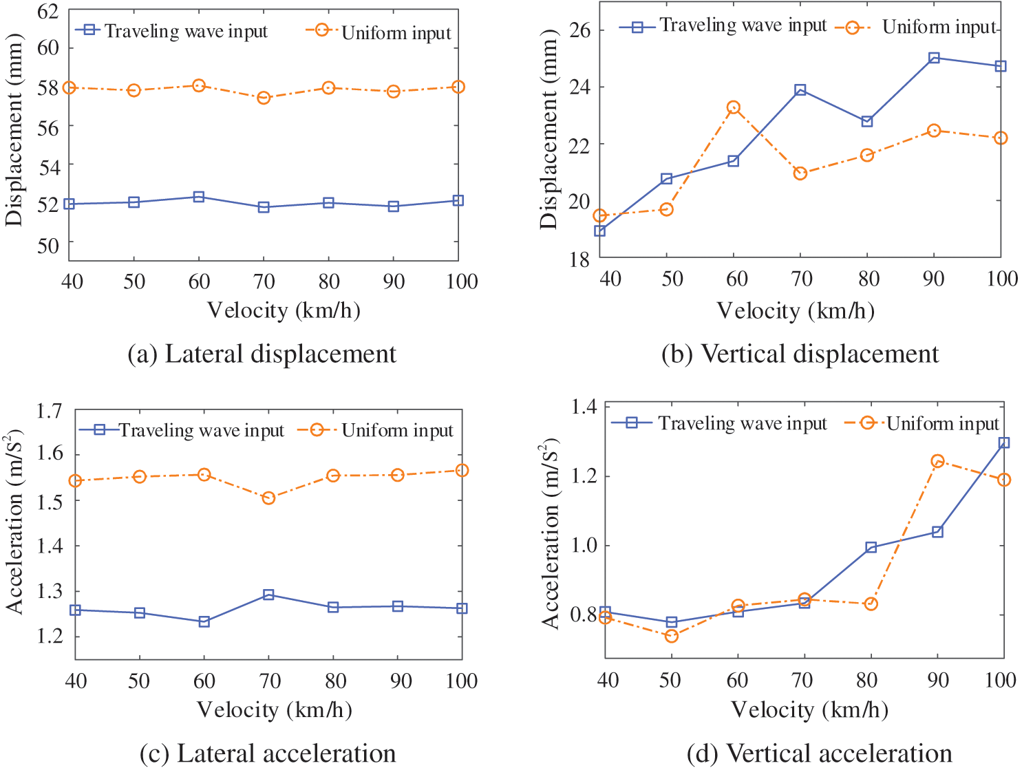
Figure 12: The relationship between the peak value of bridge mid-span vibration response and train speed
As shown in Fig. 12, the lateral bridge displacement and bridge acceleration have little relationship with the change in train speed, but the traveling wave effect reduces it significantly. The vertical bridge displacement and bridge acceleration generally increase as the train speed increases. The difference in the peak value of the bridge vibration response under the two working conditions is not obvious. Due to the existence of train axle load, it occupies a dominant position in vertical vibration. Therefore, the influence of the traveling wave effect on lateral vibration is stronger than that of vertical vibration. The relationship between the peak value of the train dynamic response and the train speed under the two conditions of uniform seismic input and traveling wave input is shown in Fig. 13.
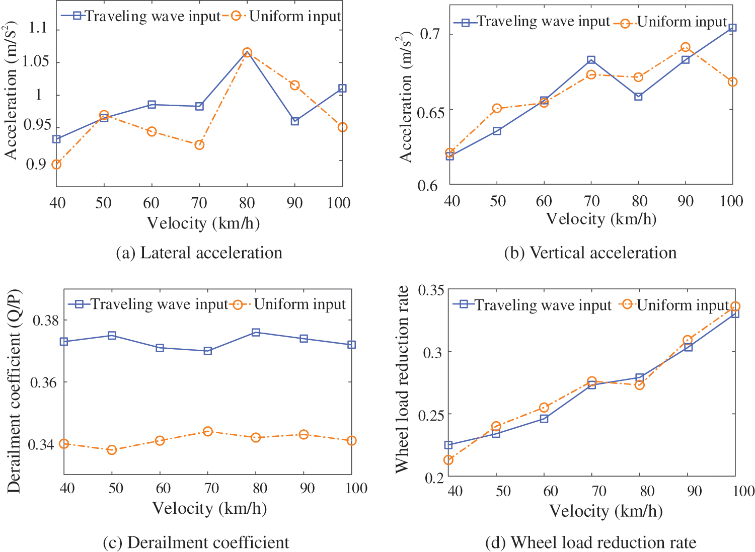
Figure 13: The relationship between the peak value of train vibration response and train speed
As shown in Fig. 13, the lateral acceleration of the train fluctuates with the increase of the train speed, while the vertical acceleration and the wheel load reduction rate show an upward trend, but the derailment coefficient of train operation will not be greatly affected. The difference between the lateral acceleration, vertical acceleration, and wheel load reduction rate of the train body is not significant. However, the train derailment coefficient is significantly increased by the traveling wave input, indicating that the traveling wave effect will threaten the train run safety.
4.3 The Influence of Seismic Intensity on the Response of the TBCS
Investigation of the influence of seismic intensity on the TBCS response, the seismic acceleration is formatted according to the seismic peak standards of 0.05, 0.1, 0.15, 0.2, 0.25, and 0.3 g. Three different seismic waves are considered, which are artificial wave, EI-Centro wave, and Taft wave. The speed of the heavy-haul train is 60 km/h, and the input of the earthquake is in accordance with the uniform excitation. The horizontal acceleration and displacement curves of the EI-Centro wave, corrected artificial wave [29], and Taft wave is shown in Figs. 2, 14, and 15, respectively. The relationship between the peak bridge dynamic response and the seismic intensity under varying seismic waves is shown in Fig. 16.
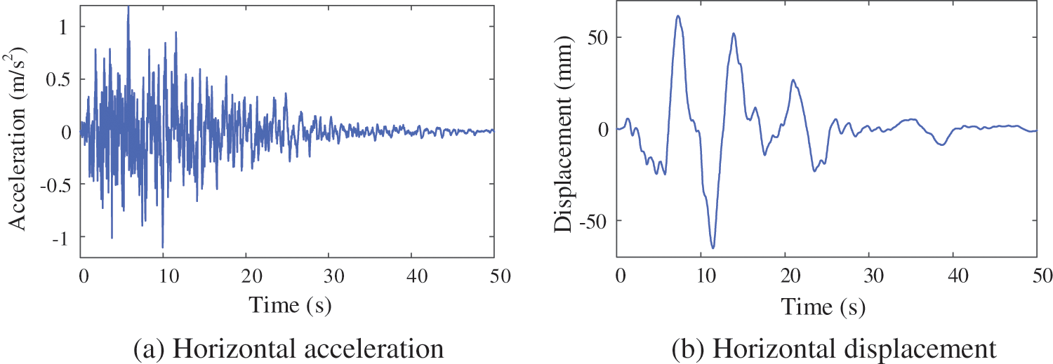
Figure 14: Time history curve of the corrected artificial wave
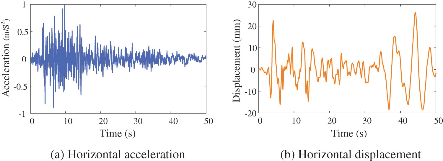
Figure 15: Time history curve of the Taft wave
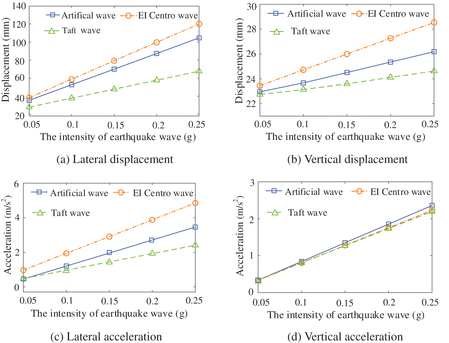
Figure 16: The relationship between the peak value of the mid-span dynamic response of the bridge and seismic intensity
Fig. 16 shows that the lateral and vertical bridge vibration responses are linearly related to the intensity of seismic waves. With the enhancement of seismic waves, the bridge dynamic response also increases, indicating that the intensity of seismic waves plays a decisive role in the bridge dynamic response. Under different seismic wave loads, the lateral vibration response and vertical displacement are very different, but the difference in bridge vertical acceleration at the mid-span is very small, indicating that the bridge has high vertical stiffness. The influence of different seismic waves on the relationship between the peak value of train vibration response and seismic intensity is shown in Fig. 17.
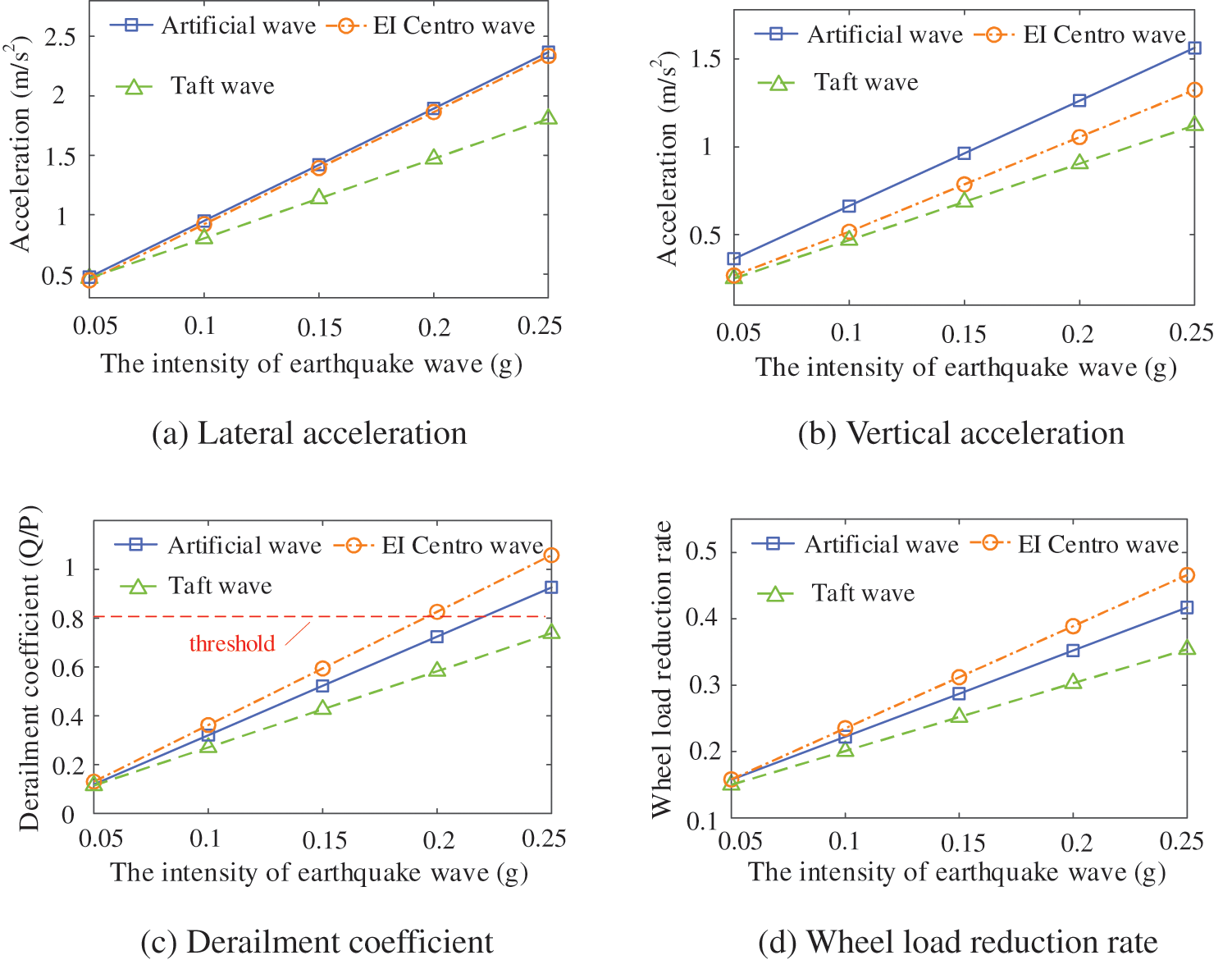
Figure 17: The influence of the relationship between the peak value of train vibration response and seismic intensity
Similarly, Fig. 17 shows that the lateral and vertical acceleration of the train body, along with the wheel load reduction rate and derailment coefficient, exhibit a linear increase in correlation with the magnitude of the seismic wave. The escalation in seismic activity compromises the operating safety of the train. A portion of the derailment coefficient exceeds the threshold of the specification when the intensity of the earthquake surpasses 0.2 g, indicating a significant risk to the safety of the train.
This research proposes a method for calculating the dynamic response of the TBCS under earthquakes (MAETB) using MATLAB and ANSYS. This method is straightforward to develop and debug, eliminating the need to obtain parameter matrices of large or complex bridges and significantly decreasing the difficulty of the TBCS vibration analysis.
Using the compiled MAETB, the dynamic parameters of the TBCS are examined for the benchmark model of a heavy-haul railway bridge. The influence of the different driving speeds, seismic wave intensities, and traveling wave effects on the dynamic response of the TBCS during an earthquake is discussed. The studies provided a few specific conclusions:
1. When compared to the scenario where the bridge is not influenced by the earthquake, the vibration response of both the bridge and the train body is notably amplified under earthquake actions. The bridge displacement increase in magnitude in the latera direction is more significant than in the vertical direction. Additionally, the train derailment coefficient and wheel load reduction rate also rise, indicating that the seismic load will directly lead to a decrease in traffic safety.
2. The seismic traveling wave effect has a significant impact on the peak time of vibration response for both bridges and trains. This effect will decrease the lateral response of the bridge but lead to a substantial increase in the train derailment coefficient, suggesting a reduction in traffic safety. The vertical displacement and acceleration of the bridge rise with increasing train speed. The lateral acceleration of the train body varies with train speed, while the vertical acceleration and wheel load reduction rate increase with higher train speeds.
3. The vibration responses of bridges and trains exhibit a linear relationship with the intensity of seismic waves. As seismic wave intensity increases, the dynamic response of both bridges and trains intensifies. When the seismic intensity surpasses 0.2 g, the partial derailment coefficient of the train exceeds the limit value of the specification. Moreover, the lateral response and mid-span vertical displacement of the bridge vary significantly under different seismic waves, underscoring the importance of selecting appropriate seismic waves for analyzing train-bridge coupling vibrations during earthquake actions.
Acknowledgement: None.
Funding Statement: This research was funded by the Open Projects Foundation of Engineering Research Center of Disaster Prevention and Mitigation of Southeast Coastal Engineering Structures of Fujian Province University (Grant No. 2022009), the National Natural Science Foundation of China (Grant No. 51708429), and the Construction Science and Technology Plan Projects of Hubei Province (Grant No. 2023011).
Author Contributions: The authors confirm contribution to the paper as follows: study conception and design: Hongyin Yang and Wei Zhang; analysis and interpretation of results: Xiucheng Zhang and Zhangjun Liu; draft manuscript preparation: Liangwei Jiang and Jinghan Wu. All authors reviewed the results and approved the final version of the manuscript.
Availability of Data and Materials: The data that support the findings of this study are available from the corresponding author, upon reasonable request.
Ethics Approval: Not applicable.
Conflicts of Interest: The authors declare that they have no conflicts of interest to report regarding the present study.
References
1. Liu YH, Lin Y, Liu WY, Zhou J, Wang J. Remote sensing perspective in exploring the spatiotemporal variation characteristics and post-disaster recovery of ecological environment quality, a case study of the 2010 Ms7.1 Yushu earthquake. Geomatics Nat Hazards Risk. 2024;15(1):2314578. doi:10.1080/19475705.2024.2314578. [Google Scholar] [CrossRef]
2. Li J, Xu LH. Seismic response characteristics and whiplash effect mechanism of continuous rigid‐frame bridges subjected to near‐fault ground motions. Bull Earthquake Eng. 2023;21(7):3719–44. doi:10.1007/s10518-023-01672-4. [Google Scholar] [CrossRef]
3. Jiang LZ, Zhang YT, Feng YL, Zhou WB, Tan ZH. Simplified calculation modeling method of multi-span bridges on high-speed railways under earthquake condition. Bull Earthquake Eng. 2020;18(5):2303–28. doi:10.1007/s10518-019-00779-x. [Google Scholar] [CrossRef]
4. Zhang YT, Jiang LZ, Zhou WB, Feng YL, Tan ZH, Chai XL. Study of bridge-subgrade longitudinal constraint range for high-speed railway simply-supported beam bridge with CRTSII ballastless track under earthquake excitation. Constr Build Mater. 2020;241(1):118026. doi:10.1016/j.conbuildmat.2020.118026. [Google Scholar] [CrossRef]
5. Kim CW, Kawatani M, Lee CH, Nishimura N. Seismic response of a monorail bridge incorporating train-bridge interaction. Struct Eng Mech. 2007;26(2):111–26. doi:10.12989/sem.2007.26.2.111. [Google Scholar] [CrossRef]
6. Gong W, Zhu ZH, Liu Y, Liu RT, Tang YJ, Jiang LZ. Running safety assessment of a train traversing a three-tower cable-stayed bridge under spatially varying ground motion. Railway Eng Sci. 2020;28(2):184–98. doi:10.1007/s40534-020-00209-8. [Google Scholar] [CrossRef]
7. Tian ZY, Lou ML. Traveling wave resonance and simplified analysis method for long-span symmetrical cable-stayed bridges under seismic traveling wave excitation. Shock Vib. 2014;2014(3):1–12. doi:10.1155/2014/602825. [Google Scholar] [CrossRef]
8. Borjigin S, Kim CW, Chang KC, Sugiura K. Nonlinear dynamic response analysis of vehicle-bridge interactive system under strong earthquakes. Eng Struct. 2018;176(3):500–21. doi:10.1016/j.engstruct.2018.09.014. [Google Scholar] [CrossRef]
9. Zeng ZP, Zhao YG, Xu WT, Yu ZW, Chen LK, Lou P. Random vibration analysis of train-bridge under track irregularities and traveling seismic waves using train-slab track-bridge interaction model. J Sound Vib. 2015;342:22–43. doi:10.1016/j.jsv.2015.01.004. [Google Scholar] [CrossRef]
10. Ishida H, Miyamoto T, Maebashi E, Iida H, Furukawa K. Safety assessment for flange climb derailment of trains running at low speeds on sharp curves. Quaet Rep RTRI. 2006;47(2):65–71. doi:10.2219/rtriqr.47.65. [Google Scholar] [CrossRef]
11. Takai H, Uchida M, Muramatsu H, Ishida H. Derailment safety evaluation by analytic equations. Quaet Rep RTRI. 2002;43(3):119–24. doi:10.2219/rtriqr.43.119. [Google Scholar] [CrossRef]
12. Chen LK, Jiang LZ, Guo W, Liu WS, Zeng ZP, Chen GW. The seismic response of high-speed railway brisdges subjected to near-fault forward directivity ground motions using a vehicle-track-bridge element. Shock Vib. 2014;2014:1–17. [Google Scholar]
13. Zhou GL, Li XJ, Qi XJ. Seismic response analysis of continuous rigid frame bridge considering canyon topography effects under incident SV waves. Earthquake Sci. 2010;23(1):53–61. doi:10.1007/s11589-009-0065-7. [Google Scholar] [CrossRef]
14. Jia HY, Zhang DY, Zheng SX, Xie WC, Pandey MD. Local site effects on a high-pier railway bridge under tridirectional spatial excitations: nonstationary stochastic analysis. Soil Dyn Earthquake Eng. 2013;52(5):55–69. doi:10.1016/j.soildyn.2013.05.001. [Google Scholar] [CrossRef]
15. Shrestha B, Hao H, Bi K. Seismic response analysis of multiple-frame bridges with unseating restrainers considering ground motion spatial variation and SSI. Adv Struct Eng. 2015;18(6):873–91. doi:10.1260/1369-4332.18.6.873. [Google Scholar] [CrossRef]
16. Li X, Li ZX, Crewe AJ. Nonlinear seismic analysis of a high-pier, long-span, continuous RC frame bridge under spatially variable ground motions. Soil Dyn Earthquake Eng. 2018;114(1):298–312. doi:10.1016/j.soildyn.2018.07.032. [Google Scholar] [CrossRef]
17. Lin YZ, Zong ZH, Bi K, Hao H, Lin J, Chen YY. Experimental and numerical studies of the seismic behavior of a steel-concrete composite rigid-frame bridge subjected to the surface rupture at a thrust fault. Eng Struct. 2020;205(1):110105. doi:10.1016/j.engstruct.2019.110105. [Google Scholar] [CrossRef]
18. Lin KQ, Xu YL, Lu XZ, Guan ZG, Li JZ. Collapse prognosis of a long-span cable-stayed bridge based on shake table test and nonlinear model updating. Earthquake Eng Struct Dyn. 2021;50(2):455–74. doi:10.1002/eqe.3341. [Google Scholar] [CrossRef]
19. An H, Lee JH, Shin S. Dynamic response evaluation of bridges considering aspect ratio of pier in near-fault and far-fault ground motions. Appl Sci. 2020;10(17):6098. doi:10.3390/app10176098. [Google Scholar] [CrossRef]
20. Zheng SX, Shi XH, Jia HY, Zhao CH, Qu HL, Shi XL. Seismic response analysis of long-span and asymmetrical suspension bridges subjected to near-fault ground motion. Eng Fail Anal. 2020;115(6):104615. doi:10.1016/j.engfailanal.2020.104615. [Google Scholar] [CrossRef]
21. Xia H, Han Y, Zhang N, Guo WW. Dynamic analysis of train-bridge system subjected to non-uniform seismic excitations. Earthquake Eng Struct. 2006;35(12):1563–79. doi:10.1002/(ISSN)1096-9845. [Google Scholar] [CrossRef]
22. Du XT, Xu YL, Xia H. Dynamic interaction of bridge-train system under non-uniform seismic ground motion. Earthquake Eng Struct. 2012;41(1):139–57. doi:10.1002/eqe.1122. [Google Scholar] [CrossRef]
23. Zhang N, Xia H, De Roeck G. Dynamic analysis of a train-bridge system under multi-support seismic excitations. J Mech Sci Technol. 2010;24(11):2181–8. doi:10.1007/s12206-010-0812-7. [Google Scholar] [CrossRef]
24. Wang SL, Zhai WM. Dynamic response of high-speed train-line-bridge system under earthquake. J Southwest Jiaotong Univ. 2011;46(1):56–62+67 (In Chinese). [Google Scholar]
25. Xia H, Zhang N, Guo WW. Coupling vibrations of train-bridge system. China: Science Publishing; 2014. p. 197–298 (In Chinese). [Google Scholar]
26. Zhu ZH, Gong W, Wang LD, Li Q, Bai Y, Yu ZW, et al. An efficient multi-time-step method for train-track-bridge interaction. Comput Struct. 2018;196(62):36–48. doi:10.1016/j.compstruc.2017.11.004. [Google Scholar] [CrossRef]
27. Zhang N, Xia H. Dynamic analysis of coupled vehicle-bridge system based on inter-system iteration method. Comput Struct. 2013;114:26–34. doi:10.1016/j.compstruc.2012.10.007. [Google Scholar] [CrossRef]
28. Xu L, Zhai W. Stochastic analysis model for vehicle-track coupled systems subject to earthquakes and track random irregularities. J Sound Vib. 2017;407:209–25. doi:10.1016/j.jsv.2017.06.030. [Google Scholar] [CrossRef]
29. Liu Z, Ruan X, Liu Z, Lu H. Probability density evolution analysis of stochastic nonlinear structure under non-stationary ground motions. Struct Infrastruct Eng. 2019;15(8):1049–59. doi:10.1080/15732479.2019.1599963. [Google Scholar] [CrossRef]
Cite This Article
 Copyright © 2024 The Author(s). Published by Tech Science Press.
This work is licensed under a Creative Commons Attribution 4.0 International License , which permits unrestricted use, distribution, and reproduction in any medium, provided the original work is properly cited.
 Downloads
 Citation Tools