
 Submit a Paper
 Propose a Special lssue
 Open Access
ARTICLE

Numerical Analysis of Fiber Reinforced Polymer-Confined Concrete under Cyclic Compression Using Cohesive Zone Models
1 China Communications Construction Rail Transit Subsidiary, Bejing, 100000, China
2 China Communications Construction Company Limited, Beijing, 100000, China
3 School of Civil Engineering, Fujian University of Technology, Fuzhou, 350118, China
* Corresponding Author: Wei Zhang. Email:
Structural Durability & Health Monitoring 2024, 18(5), 599-622. https://doi.org/10.32604/sdhm.2024.051949
Received 19 March 2024; Accepted 10 May 2024; Issue published 19 July 2024
 View Full Text
 Download PDF
Abstract
This paper examines the mechanical behavior of fiber reinforced polymer (FRP)-confined concrete under cyclic compression using the 3D cohesive zone model (CZM). A numerical modeling method was developed, employing zero-thickness cohesive elements to represent the stress-displacement relationship of concrete potential fracture surfaces and FRP-concrete interfaces. Additionally, mixed-mode damage plastic constitutive models were proposed for the concrete potential fracture surfaces and FRP-concrete interface, considering interfacial friction. Furthermore, an anisotropic plastic constitutive model was developed for the FRP composite jacket. The CZM model proposed in this study was validated using experimental data from plain concrete and large rupture strain (LRS) FRP-confined concrete subjected to cyclic compression. The simulation results demonstrate that the proposed model accurately predicts the mechanical response of both concrete and FRP-confined concrete under cyclic compression. Lastly, various parametric studies were conducted to investigate the internal failure mechanism of FRP-confined concrete under cyclic loading to analyze the influence of the inner friction plasticity of different components.Keywords
The fiber-reinforced polymer (FRP) is a lightweight, high-strength, easy-to-construct, and corrosion-resistant material with promising applications in the construction industry [1–4]. One of its typical implementations is the use of FRP-confined concrete columns. Since the concept of FRP-confined concrete was first proposed, more than 200 studies [5–7] have been conducted to investigate its compressive behavior. This study comprehensively reviews research and application progress in concrete-filled FRP tubular members. It covers various concrete types, including seawater and sea-sand, lightweight aggregate, recycled aggregate, ultrahigh-performance, and geopolymer concrete. It examines these materials’ mechanical properties, durability, and innovative applications, especially in harsh environmental conditions. It also explores new FRP tube shapes, such as arch structures, and their potential applications in civil engineering. The review aims to provide a reference for future research and practical application in this field. The studies [8–11] explore advanced topics in civil engineering, mainly focusing on FRP-confined concrete structures. They delve into the behavior of FRP-confined concrete columns, examining factors like stress reduction and recovery, the impact of concrete core properties, and the effects of column shape and FRP material properties on structural performance. The research encompasses various concrete types (including high-strength and ultra-high-performance concrete) and FRP materials, highlighting the complexities and challenges in optimizing these systems for enhanced structural integrity and performance in various engineering applications.
The abovementioned studies, while advancing the understanding of FRP-confined concrete structures, have a notable weakness regarding the failure mechanism on their long-term performance and durability under cyclic and fatigue loading. This deficiency restricts the ability to fully assess how these structures will withstand repetitive stress over time, a crucial factor in real-world construction scenarios. Addressing this gap is essential for a comprehensive understanding of the structures’ resilience, especially in environments prone to regular loading and unloading cycles.
In recent years, there has been an emergence of new types of FRP materials for seismic reinforcement of concrete columns. Apart from traditional materials like aramid FRP (AFRP), carbon FRP (CFRP), and glass FRP (GFRP), which have rupture strains of less than 3%, 1.5%, and 2.5%, respectively [12], a new type called large-rupture-strain FRP (LRS FRP) has gained popularity. LRS FRP, known for its good ductility with a rupture strain of more than 5%, is typically manufactured using polyethylene naphthalate (PEN) fibers or polyethylene terephthalate (PET) fibers, resulting in a relatively low elastic modulus. Consequently, numerous experiments and theoretical studies [13–15] have been conducted to investigate the cyclic compression behavior of LRS FRP-confined concrete columns. These studies have also developed stress-strain models to predict the mechanical behavior of FRP-confined concrete under both monotonic and cyclic compression conditions.
While there has been significant research on FRP-confined concrete, most of it has focused on the macroscopic scale. Limited attention has been given to studying the mechanistic aspects of this structure at the mesoscopic scale, which considers the interaction within the concrete fracture surface and the FRP-concrete interface. Therefore, it is important to establish a mesoscale model to gain a better understanding of the internal fracture mechanisms of FRP-confined concrete under cyclic compression conditions. Since FRP-confined concrete is a composite structure that relies on the transfer of internal forces through interfaces, the cohesive zone model (CZM) is a suitable choice. Because CZM can accurately describe the normal and tangential mechanical damage behavior between interfaces, as well as detailed friction behavior between interfaces, it has significant advantages in characterizing interface problems compared to traditional continuous or contact elements, including the interface properties between FRP and concrete [16–18], as well as the interaction between cracks in concrete before and after cracking [19–22].
In order to understand the internal fracture mechanisms of FRP-wrapped concrete under cyclic compression conditions, this study developed an FE model based on the CZM. Zero-thickness cohesive elements were used to represent the potential fracture surfaces of concrete and the interface between FRP and concrete. Damage plastic constitutive models were proposed to account for the interface’s damage, plastic behavior, and friction effect. The proposed model was validated using different experiments, and subsequent analyses were conducted to investigate the internal fracture and failure mechanisms.
2 Modeling of the FRP-Confined Concrete Based on the 3D CZM Model
The 3D modeling method used in this study is based on the insertion of cohesive elements. To characterize the mechanical behavior of the concrete potential fracture surfaces and FRP-concrete interface, coherent elements (COH3D6) were adopted, as shown in Fig. 1. Additionally, solid elements (C3D4) and shell elements (S3R) were used to simulate the concrete and FRP composite jacket. The selection of C3D4 tetrahedral elements instead of C3D8 hexahedral elements is because the C3D4 elements can generate more random potential fracture surfaces, thus making the simulation more realistic. Let’s take an FRP-confined concrete column as an example. First, the concrete model with potential fracture surfaces needs to be built. As depicted in Fig. 1a, the continuous solid elements were separated, and then zero-thickness cohesive elements were inserted into their interfaces using the method proposed in [16–18]. Once the concrete model is constructed, the FRP-concrete interface and FRP composite jacket should be added. The method of inserting the FRP-concrete interface and FRP jacket, as described in [16–18], can be divided into the following steps. Firstly, Mark the outer surfaces of the concrete column and record the corresponding element and node information. Secondly, Copy the element and node information of the marked surfaces and generate shell elements as FRP composite jackets. Finally, based on the element and node information of the outer surfaces and shell elements, generate cohesive elements as an FRP-concrete interface. The brief flowchart of modeling can be seen in Fig. 1c.
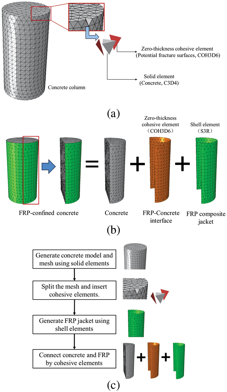
Figure 1: Modeling of the FRP-confined concrete based on the application of cohesive elements: (a) modeling of concrete; (b) modeling of FRP-confined concrete; (c) flowchart of modeling
2.2 Constitutive Models Considering Interface Plasticity and Damage
In the CZM model, solid elements are assumed to be linear elastic, while all damage, plasticity, and interface friction behaviors occur within the cohesive elements. Therefore, this section will provide a detailed introduction to the constitutive model used for the cohesive elements.
(1) Single-mode damage plastic relation
To characterize the loading, unloading, and reloading mechanical behavior of the FRP-concrete interface, the exponential softening relationship and linear unloading and reloading relationship were adopted, as shown in Fig. 2.
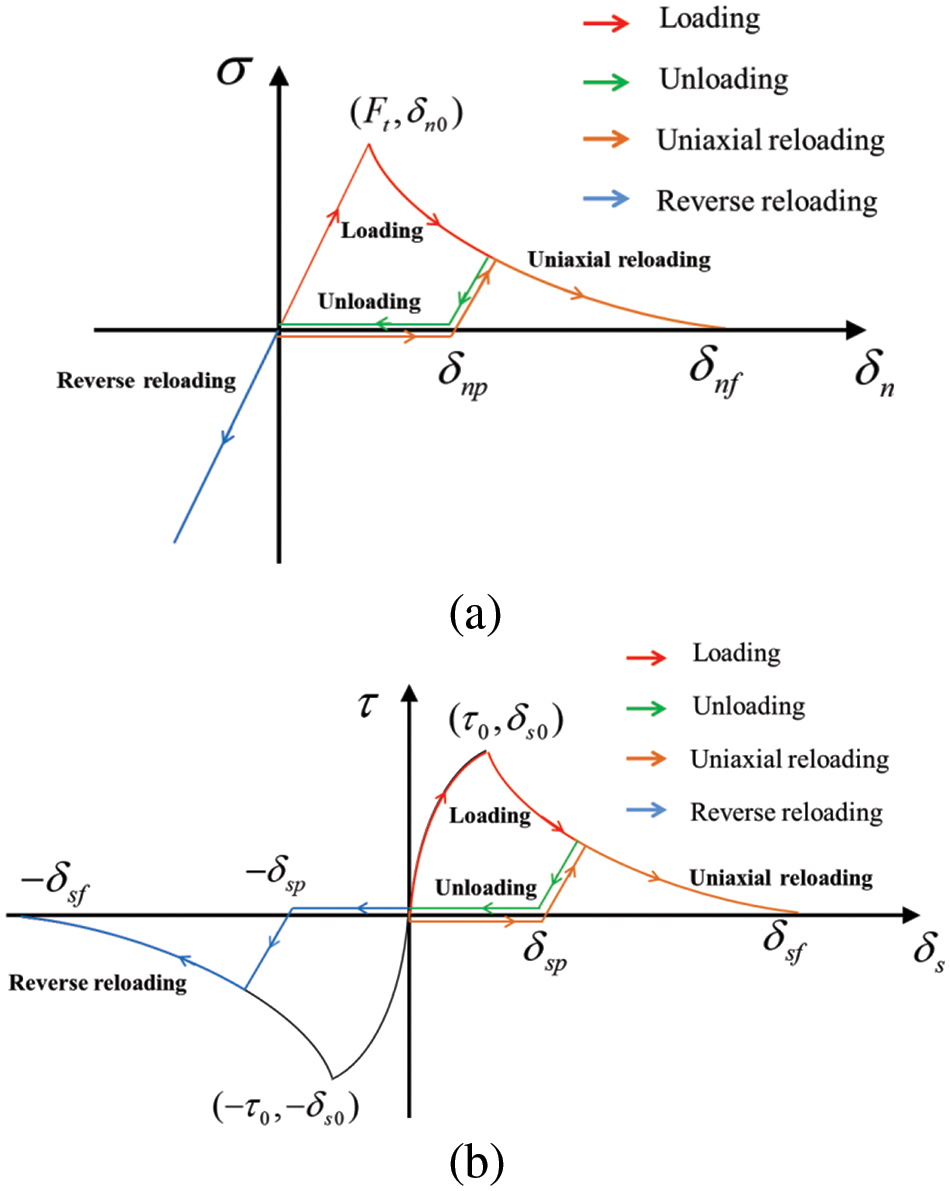
Figure 2: Stress-displacement relation considering damage and plastic under single-mode condition: (a) normal direction; (b) tangential direction
For mode I, the interface was consumed undamaged under compression. In monotonic loading conditions, the normal stress σ can be expressed as follows:
where kn is the normal stiffness; δn is the normal displacement; δn0 and δnf are the damage initial displacement and failure displacement in the normal direction, respectively; D is the nominal damage factor, which can be given as follows [17]:
As shown in Fig. 2a, when the interface is in the unloading and reloading states, the stress satisfies the following expression:
where d is the damage factor considering the plasticity; δnp is the plastic displacement in the normal direction, which can be given as follows according to the geometry relation in Fig. 2a:
where Dmax is the historical maximum nominal damage factor; δnmax is the corresponding normal displacement to Dmax.
The explanation of the damage factor d can be seen in Fig. 3. When considering the plasticity, the unloading, and reloading stiffness (1 − d)kn should always be much higher than the one (1 − d)kn without considering plasticity. This indicates that the damage factor d should always be much less than the nominal damage factor D. Therefore, As shown in Fig. 3a, the damage factor d can be assumed to be d = Dn, ensuring that D is always greater than d when D is within the range of 0 to 1. In this study, n is assumed to be 10 through the repeat trials and validation.
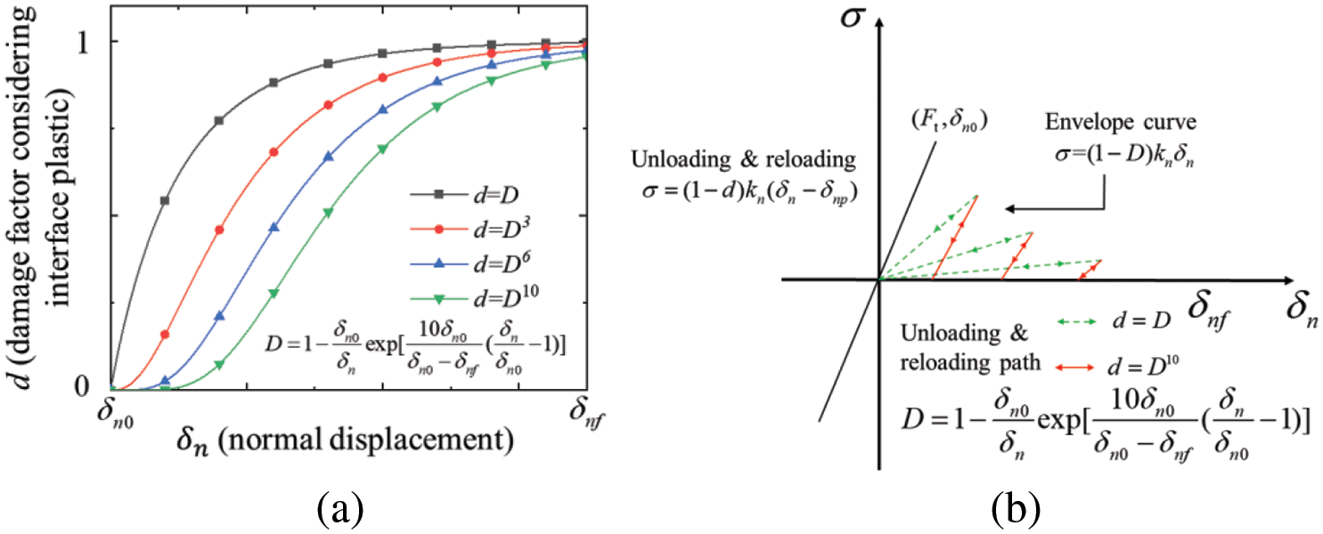
Figure 3: Relations between damage factor d and nominal damage factor D: (a) damage factor with different parameters; (b) the unloading and reloading path with different damage factors (normal direction)
For mode II, as shown in Fig. 2b, in monotonic loading condition, the shear stress τ can be given as follows:
where τ0 is the shear strength; ks is the normal stiffness, ks = τ0/δs0; δs is the tangential displacement, in 3D condition, δs = (δ2sx + δ2sy)1/2; δs0 and δsf are the damage initial displacement and failure displacement in the tangential direction, respectively; D is the nominal damage factor, which can be given as follows [17]:
In unloading and reloading conditions, the isotropic plastic and damage behavior was adopted to characterize the shear stress in the tangential direction (2D) or tangential plane (3D). As shown in Fig. 2b, the unloading and reloading stress can be given as follows:
where d is the damage factor, which is calculated by d = Dn, same as mode-I, n = 10; δsp is the plastic displacement in the tangential direction or tangential plane, it is a positive value, which can be expressed as follows:
where δsmax is the corresponding tangential displacement to Dmax.
(2) Mixed-mode damage plastic relation
In the mixed-mode condition (mode I and mode II), the damage and plastic behavior can be explained through Fig. 4. The parabola stress criterion [17] was adopted to determine whether the interface is starting to fail, which can be given as follows:
where Ft is the tensile strength of the interface.
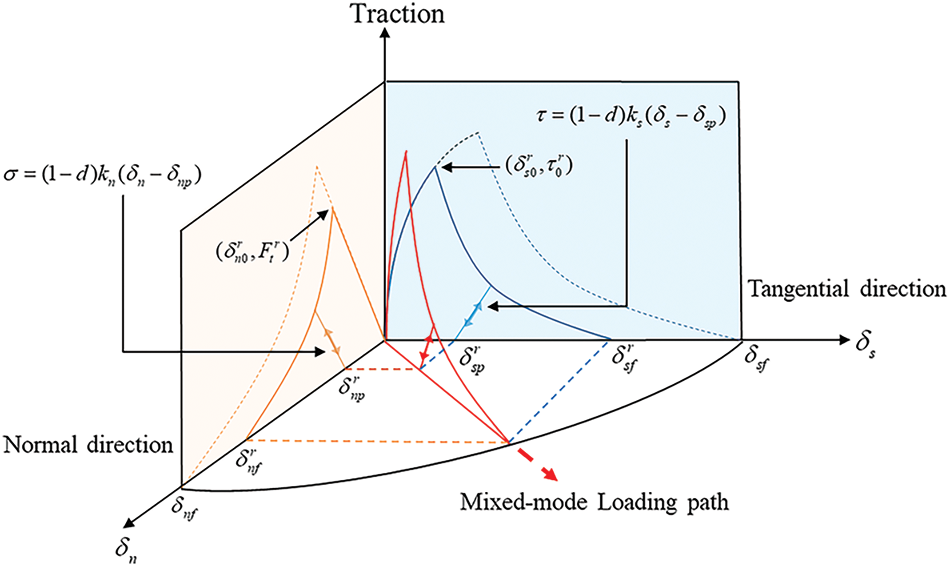
Figure 4: Mixed-mode stress-displacement relation considering damage and plastic
Thus, according to the geometry relation in Fig. 4, the relative damage initial displacements δn0r and δs0r [17] can be expressed as follows:
where δn0r and δs0r are the projections of the initial damage displacement in normal and tangential directions under a mixed-mode loading path.
Similarly, the relative damage initial displacements δnfr and δsfr [17] can be expressed as follows:
where δnfr and δsfr are the projections of the failure displacement in normal and tangential directions. Gn and Gs are the fracture energies in the normal and tangential directions, which can be obtained by calculating the area under the stress-displacement curves in Fig. 2.
According to the red line in Fig. 4, the total displacement δ, initial damage displacement δ0 and failure displacement δf in mixed-mode loading conditions can be expressed as follows:
Thus, the damage factor d and nominal damage factor D can be given:
In addition, based on the projection, the expression for plastic displacements can be written as:
(3) Friction effect
Once the damage initiates in the interface, the friction stresses would be involved in the tangential stresses under the interface compression condition. According to the friction law, the friction stress can be calculated under the interface non-slippage condition and interface slippage condition.
1) Interface non-slippage condition
In the interface non-slippage condition, as shown in Fig. 5, the maximum frictional stress provided by the damaged interface is significant enough to enable the normal transmission of shear stresses; the friction stress Tf in this condition can be expressed as follows:
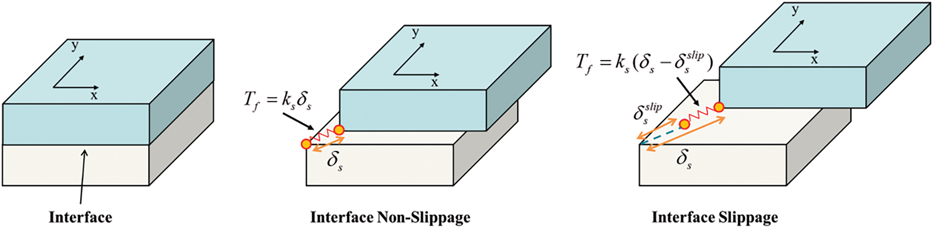
Figure 5: Friction stress calculation under different conditions
where Tfmax is the maximum friction stress that the interface can provide, which can be given as follows:
where f is the friction coefficient.
2) Interface slippage condition
In the interface slippage condition, as shown in Fig. 5, the slippage has happened in the interface. Thus, when calculating the friction stress (in the 3D case), this portion of the slippage should be excluded:
where δsxslide and δsyslide are the projections of the slip displacement in the tangential plane.
Besides, in the interface slippage condition, when the maximum frictional stress is unable to prevent further slippage, an update to the slip displacements δsxslide and δsyslide should be implemented:
where δsxslide* and δsyslide* are the updated slip displacements.
(4) Stress expressions
Based on the damaged plastic relation and friction effect of the interface, the stress expression for the interface can be formulated as follows:
1) Elastic stage:
2) Non-linear stage:
For normal stress:
For shear stresses:
To implement the damage plastic constitutive model proposed in this study into the FE model, a VUMAT subroutine for EXPLICITE/ABAQUS [23] was developed based on the FORTRAN language. The stress calculation’s coding flowchart is illustrated in Fig. 6.
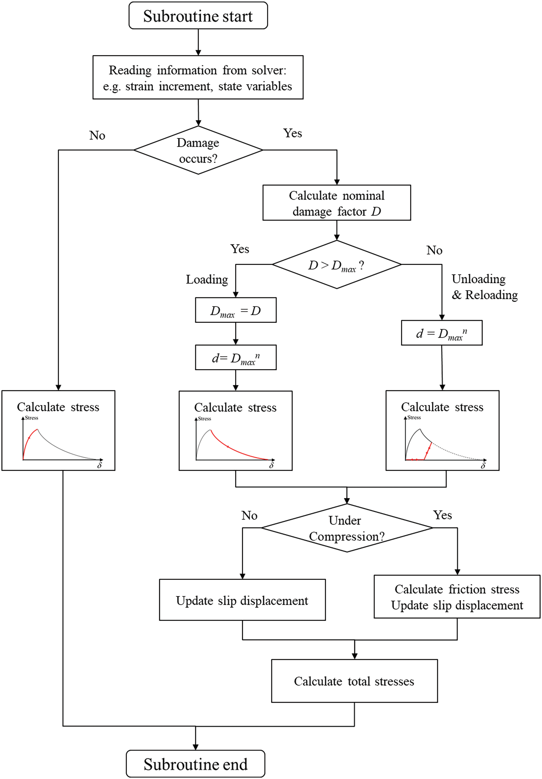
Figure 6: Friction stress calculation under different conditions
2.2.2 Concrete Potential Fracture Surfaces
The constitutive model for concrete potential fracture surfaces is similar to the FRP-concrete interface. The only difference is that the stress-displacement envelope curve of the potential fracture surfaces follows the bilinear relationship, as shown in Fig. 7. Taking single-mode loading in the normal direction as an example, the stresses can be expressed as follows:
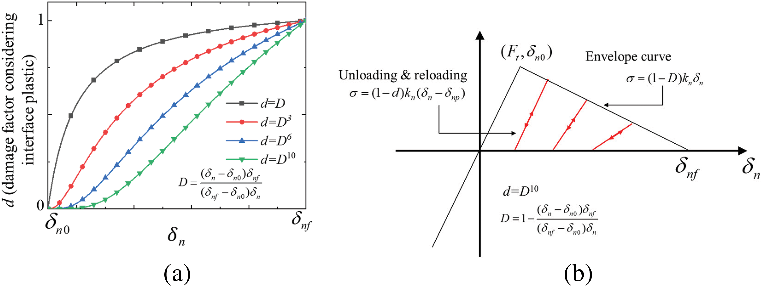
Figure 7: Damage factor of the concrete potential fracture surfaces: (a) relations between damage factor d and nominal damage factor D; (b) the unloading and reloading path (normal direction)
where D is different from the one in the FRP-concrete interface, which can be given as follows:
In mixed-mode conditions, the damage initiation of the interface follows the square stress criterion, which can be given as follows:
Similar to the FRP-concrete interface, the damage initial displacements in the mixed-mode can be expressed as follows:
Besides, the failure displacements can also be similarly calculated by:
Finally, the damage factor d and nominal damage factor D can be given as follows:
Except for the parameters mentioned above, all other parameters, such as δnp, δsp, x, δsp, y, Tf, and so on, can be calculated using Eqs. (14)–(18).
Finally, the stresses of the potential fracture surfaces in the mixed-mode condition can be formulated as follows:
1) Elastic stage:
2) Nonlinear stage:
As mentioned earlier, the stresses can be calculated using Eqs. (20)–(22).
The FRP composite is cast by combining FRP fabric and epoxy resin, making its mechanical response more complex than a single material. According to the previous studies [7,12], as shown in Fig. 8b, an incremental bilinear stress-strain relationship is employed to characterize the stress-strain behavior of the FRP composite jacket (polyethylene naphthalene, PEN) during monotonic loading. Besides, the plasticity is considered. As shown in Fig. 8a, when concrete undergoes compression, causing expansion of the cross-section, the FRP composite jacket is subjected to tension, resulting in slippage and consequently reflecting corresponding plasticity in its mechanical performance.
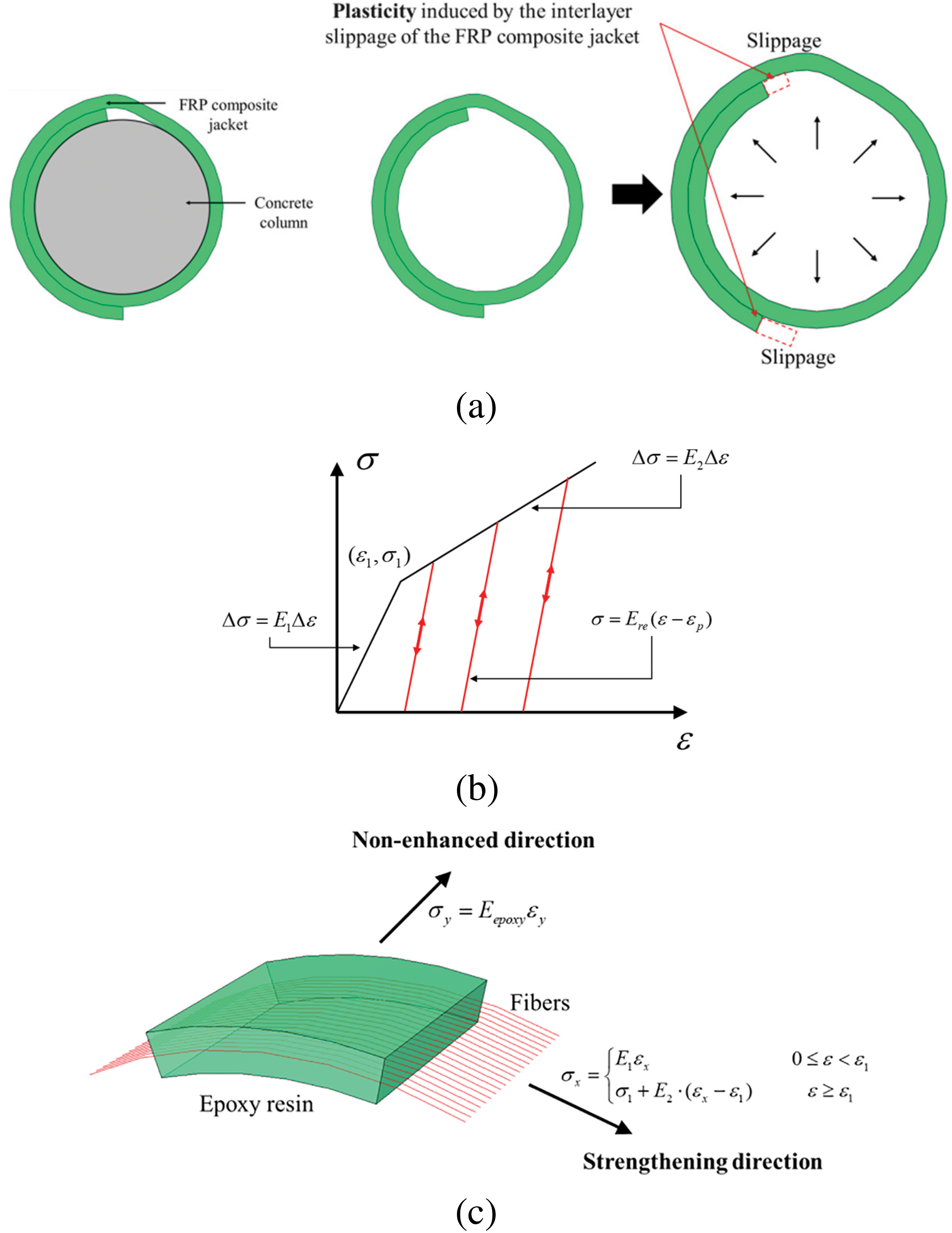
Figure 8: Constitutive model of FRP composite jacket: (a) slippage mechanism; (b) the unloading and reloading path; (c) internal components of the FRP composite jacket
Therefore, the stress-strain envelope curve of the FRP composite jacket in its strengthening direction can be given as follows:
where σx and εx are the stress and strain in the strengthening direction; E1 and E2 are the elastic modulus in two batches; σ1 and ε1 are the stress and strain value of the turning point in Fig. 8b.
When an FRP composite jacket is under unloading and reloading, its stress-strain relation in the strengthening direction can be expressed as follows:
where Ere is the unloading and reloading stiffness; εp is the plastic strain, which can be obtained according to the maximum stress σmax and the corresponding strain εmax during the loading history:
As shown in Fig. 8c, in the non-enhanced direction, the stress is mainly provided by epoxy resin, which can be given as follows:
The constitutive models of concrete potential fracture surfaces and FRP composite jackets were also implemented by user subroutine VUMAT in EXPLICITE/ABAQUS.
3 Validation of the Proposed Model
3.1 Cyclic Compression Test of Plain Concrete [24]
To ensure the accuracy of the established FE model for FRP-confined concrete in this study, it is essential first to ensure that the plain concrete FE model accurately reflects its mechanical characteristics under cyclic loading. The experimental study about low-strength concrete carried out by Ozcelik [24] was chosen to validate the accuracy of the proposed model. The dimension of the standard cylinder test specimens was 150 mm × 300 mm, as shown in Fig. 9a. The specimen C2-2-B7-10-1 was chosen to validate the FE model. According to the reference [24], a cyclic loading controlled by displacement was applied to the concrete column in the FE model, as shown in Fig. 9b. The quasi-static method was adopted to solve the numerical models by EXPLICITE/ABAQUS. A typical model on the Intel Xeon 8375C processor (16 threads parallel computing) takes approximately 3 h to compute.
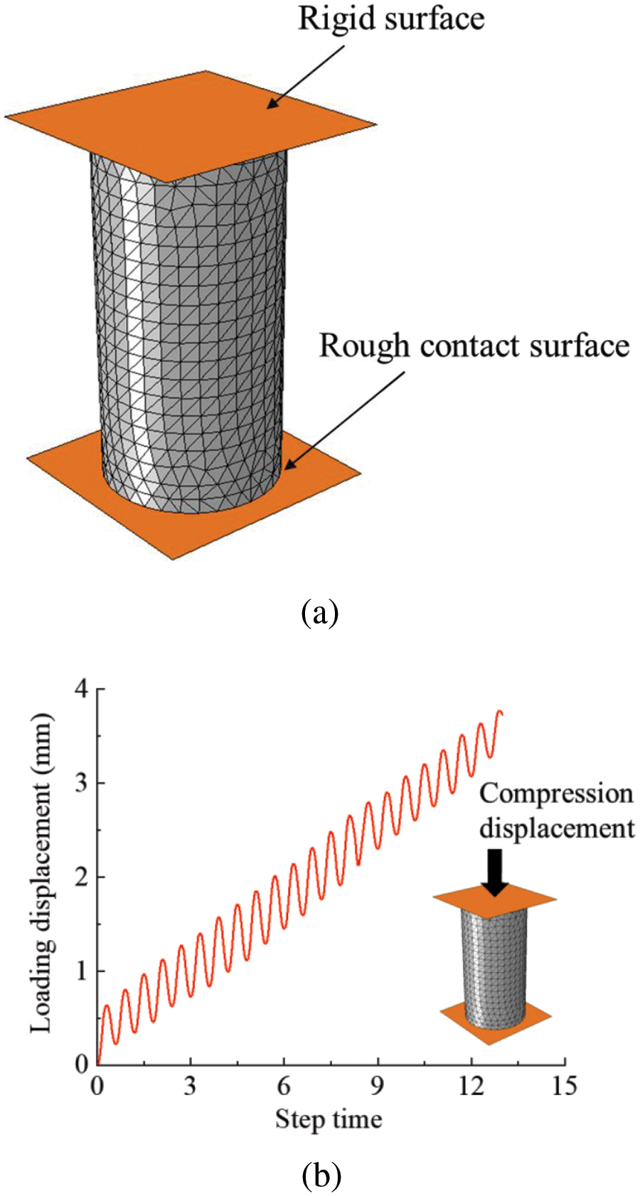
Figure 9: FE model of concrete under cyclic compression: (a) FE model; (b) loading regime
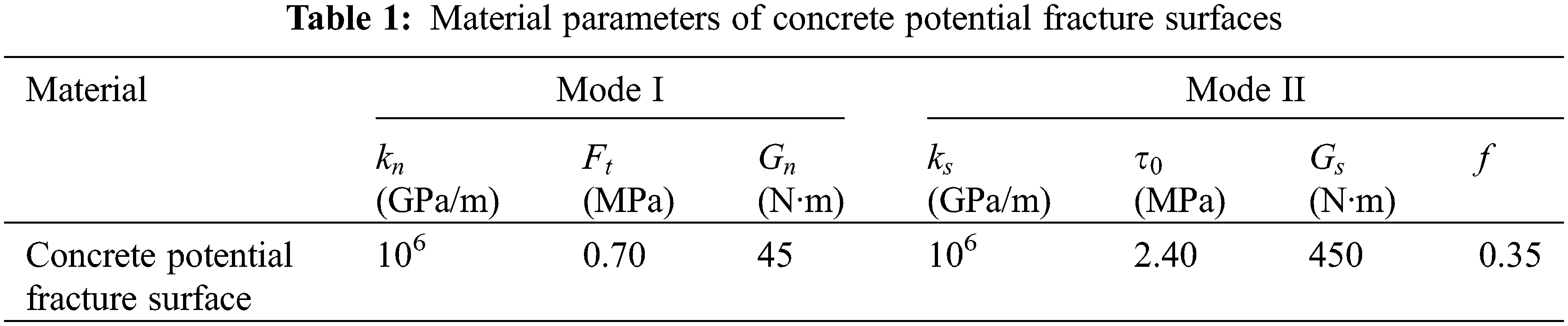
The FE model was built using the modeling method proposed in this study. Through mesh sensitivity analysis, a typical FE model contains about 35,000 nodes, 9000 solid elements, and 17,000 cohesive elements. Through the experimental results [24], repeat trials, and relative references about the CZM model [19–22], the material parameters of the concrete potential fracture surfaces are listed in Table 1. Besides, the elastic modulus and Poisson’s ratio for concrete solid elements are about 15 GPa and 0.22, respectively.
By calculation, the simulated stress-strain hysteresis curve of plain concrete under cyclic loading and the post-failure morphology (cracks were represented by deleting the cohesive elements whose damage factor d reached 1) are illustrated in Fig. 10. By comparing the simulated and experimental curve results, the established model effectively characterizes the stress hysteresis behavior of concrete under cyclic loading. Additionally, the loading and unloading stiffness and plastic strain of concrete at different stages align well with the experimental data. The model simulated the degradation of concrete’s unloading stiffness and energy dissipation during the loading and unloading process. Furthermore, as shown in Fig. 10b, the simulated final fracture morphology exhibits shear failure along a 45-degree inclined plane, with crack propagation occurring in the midsection of the concrete. This also aligns with the described results in the reference [24].
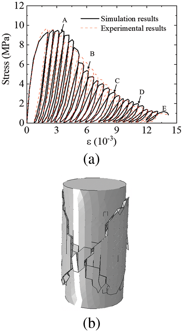
Figure 10: Simulation results of plain concrete under cyclic compression loading: (a) stress-strain curves; (b) fracture morphology (deformation magnified five times)
Fig. 11 shows the propagation of cracks in the concrete during the fracture process. 5 typical states in Fig. 10a were chosen to be analyzed. It exhibits a classic failure process, where the concrete gradually cracks in the midsection, eventually forming a continuous inclined fracture surface that penetrates the entire concrete completely, leading to a loss of load-bearing capacity in the concrete.
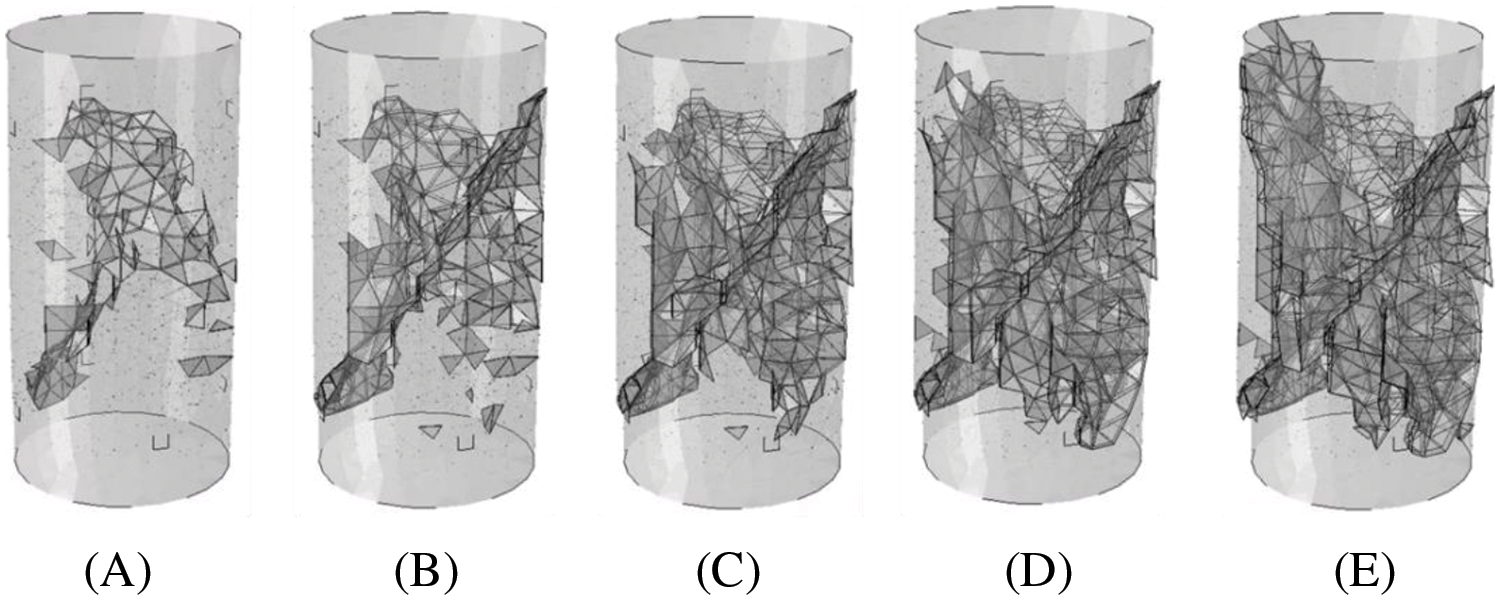
Figure 11: Crack distribution of concrete during the fracture process in different states (deformation magnified five times)
3.2 Monotonic Compression Test of FRP-Confined Concrete [7]
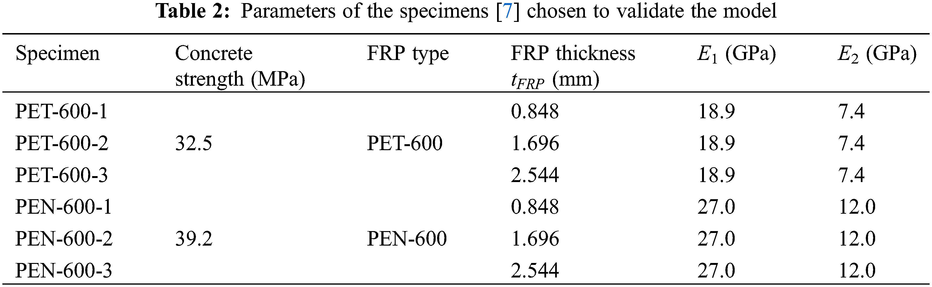
It is crucial to validate the accuracy of the proposed model under monotonic compression conditions before examining the cyclic behavior of FRP-confined concrete columns. The experiments carried out by Dai et al. [7] were chosen in this study. The typical specimen and the corresponding FE model are shown in Fig. 12. The cylinder test specimens’ dimensions were 152 mm × 305 mm. This study selected two types of large-rupture-strain FRP jacket types: PEN-600 and PET-600. The parameters of specimens chosen to validate the model are listed in Table 2. Additionally, CFRP strips, each with a width of 25 mm and a thickness of 0.34 mm, were applied to the top and bottom.
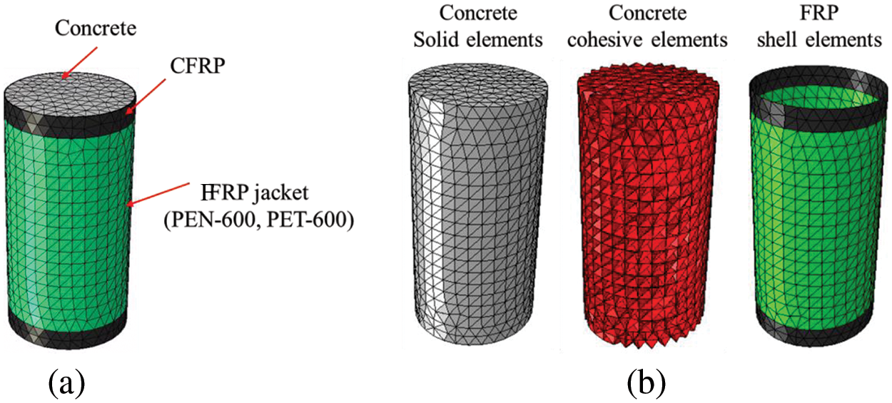
Figure 12: FE model of FRP-confined concrete column: (a) FE model; (b) model composition
One typical FE model contains about 43,000 nodes, 10,500 solid elements, 22,000 cohesive elements, and 1500 shell elements. Through the experimental results [7], repeat trials, and relative references about the CZM model [19–22], the material parameters applied in the concrete potential fracture surfaces and FRP-concrete interface are listed in Table 3.
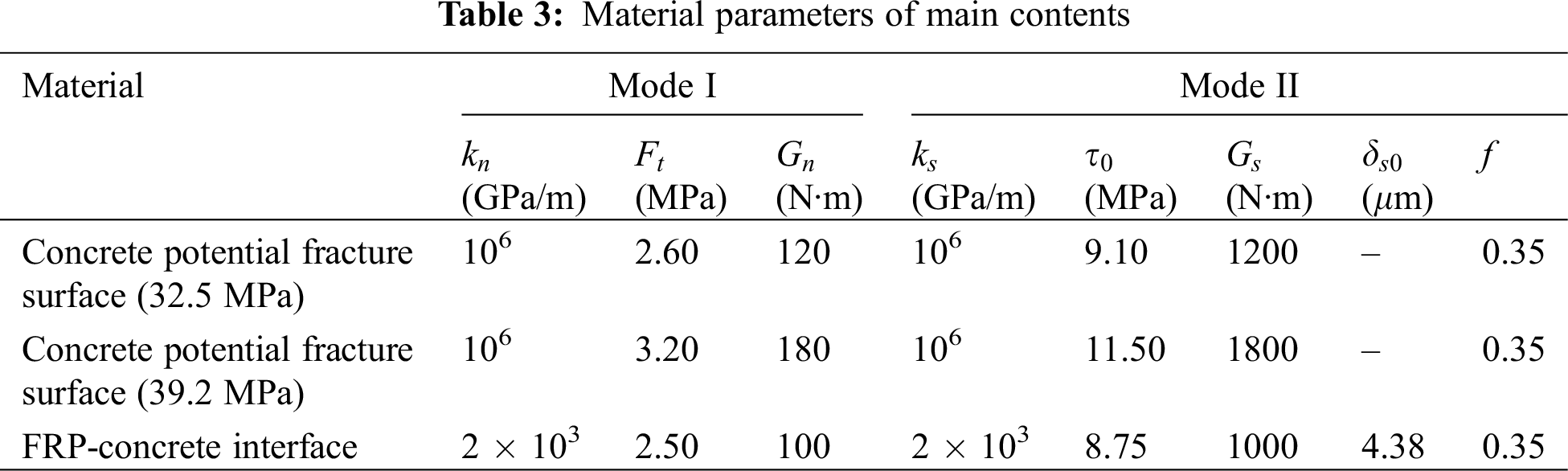
It should be noted that the FRP-concrete interface is composed of a mixture of epoxy resin and concrete surface mortar. Since the strength and fracture energy of epoxy resin are much greater than those of concrete surface mortar, the strength and fracture energy of the FRP-concrete interface should be taken as the parameter values of the concrete surface mortar. These parameters are generally chosen to be slightly weaker than the core concrete. Besides, the elastic modulus and Poisson’s concrete ratio are about 30 GPa and 0.22, respectively. The elastic modulus of CFRP is about 120 GPa. For the FRP jacket, considering the epoxy resin and the externally bonded fiber sheet [7,12], the section stiffness per unit width EFRP · tFRP of the FRP jacket has been uniformly increased by 15 GPa·mm. Eepoxy (Eq. (33)) in a non-enhanced direction is about 2 GPa. As for the unloading elastic modulus Ere of the FRP jacket, the repeat trials in Section 3.3 set it to Ere = 5E1.
Fig. 13 shows the comparison of stress-strain curves between simulation and experiments. The stress-strain curve of FRP-confined concrete columns exhibits a bilinear pattern. When the stress reaches the compressive strength of concrete, the curve shows a turning point, after which the stress increases with a lower slope as the strain continues to grow. Moreover, in the experiment, when the stiffness of the FRP jacket is insufficient, there is a slight decrease in stress after reaching the strength of the concrete. This phenomenon is also reproduced in the simulation results.
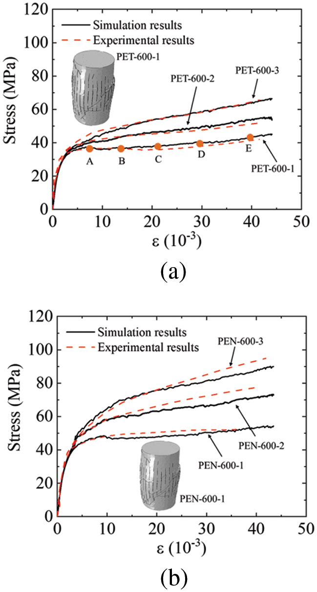
Figure 13: Simulation results of FRP-confined concrete under monotonic compression conditions: (a) PET-600; (b) PEN-600
In addition to stress-strain curves, the fracture pattern in the concrete during the cyclic loading process was analyzed, five typical states in Fig. 13a (PET-600-1) were extracted, and the corresponding crack distribution diagram was shown in Fig. 14. In the early stages of the loading process, cracks mainly initiated in the midsection of the specimen. Although concrete exhibits diagonal fracture surfaces in the middle like plain concrete (as shown in Fig. 11), the presence of the FRP protective layer results in a more complex distribution of cracks within the interior. The cracks gradually spread throughout the concrete column as the loading progressed. Unlike plain concrete, as shown in Fig. 11, the cracks in the FRP-confined concrete are distributed extensively, and eventually, the concrete is effectively crushed into numerous small fragments. This indicates that in the later stages of loading, the internal force transmission in the concrete primarily relies on the contact and friction effects between these fragments, and the FRP jacket effectively prevents the spalling of these concrete fragments.
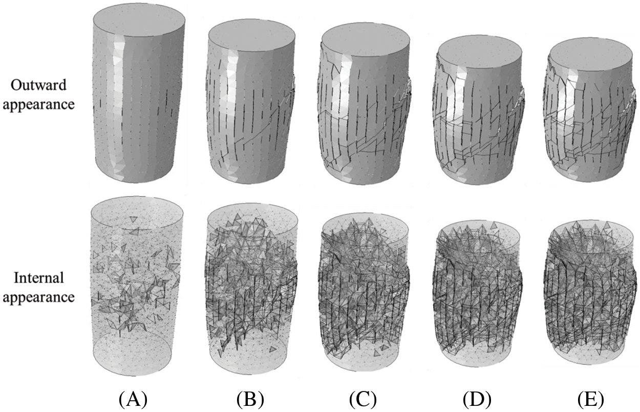
Figure 14: Crack distribution of FRP-confined concrete during the fracture process in different states (deformation magnified five times)
3.3 Cyclic Compression Test of Plain Concrete [24]
To validate the accuracy of the FRP-confined concrete FE model under cyclic compression conditions, the experiment carried out by Bai et al. [12] was chosen because this experiment constitutes the subsequent research based on the reference [7] selected in Section 3.2. The specimens used in the experiment are concrete columns wrapped with a PEN-900 FRP jacket, and all the specimens’ dimensions are the same as the ones mentioned in Section 3.2. The specimen PEN-b1-1-A has been selected to validate the model. The circular surface of the concrete was wrapped with a PEN FRP jacket with a thickness of 1.272 mm. As shown in Fig. 15, a cyclic compression loading controlled by displacement was applied to the specimen.
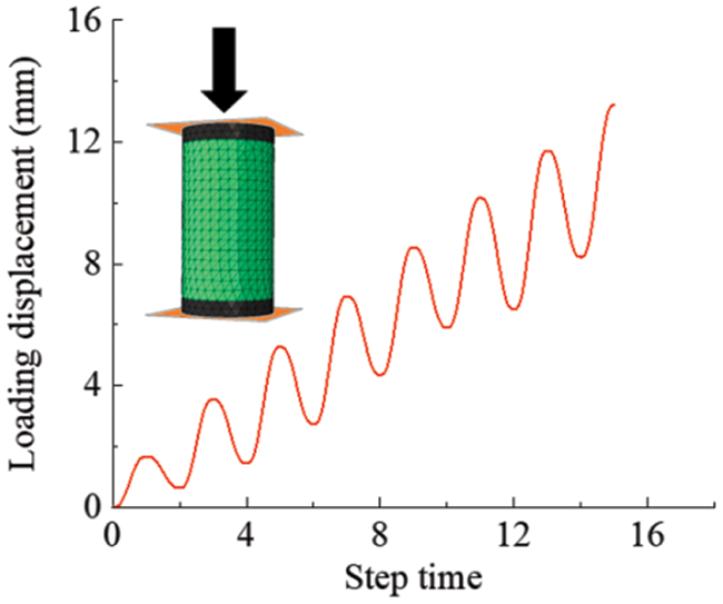
Figure 15: Loading regime of the FRP-confined concrete column under cyclic loading
As in Section 3.2, one typical FE model contains about 43,000 nodes, 10,500 solid elements, 22,000 cohesive elements, and 1500 shell elements. Through the experimental results [12], repeat trials, and relative references about the CZM model [19–22], the material parameters applied in the concrete potential fracture surfaces and FRP-concrete interface are listed in Table 4. The other parameters are the same as in Section 3.2.
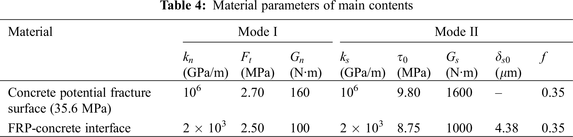
Fig. 16 shows the simulation results of the proposed FRP-confined concrete FE model under cyclic loading conditions. Due to the reinforcing effect of the FRP protective jacket, the stress-strain envelope curve of the specimen exhibits an ascending bilinear relationship. As the loading progresses, the hysteresis phenomenon in the stress-strain curve becomes increasingly significant, and the area of the hysteresis loop gradually increases. In addition, it can be noted that when the stress approaches 0, both the unloading and reloading stiffnesses decrease significantly. As shown in Fig. 16a, the above phenomena obtained from the simulation can also be observed in the experiments, and the curves from the simulations align well with the experimental results in terms of shape and magnitude, which means the proposed model can appropriately characterize the cyclic mechanical response of FRP-confined concrete.
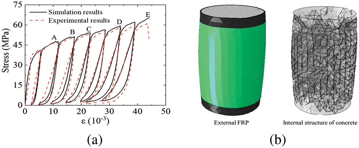
Figure 16: Simulation results of FRP-confined concrete under cyclic compression loading: (a) stress-strain curves; (b) fracture morphology (deformation magnified three times)
In order to gain a deeper understanding of the interaction between concrete and FRP jackets during the cyclic loading process of FRP-confined concrete columns, as shown in Fig. 17a, a typical cyclic process has been selected (three states were chosen, A: maximum point; B: turning point; C: minimum point), and as shown in Fig. 17b, the radial displacement of the specimen’s 1/2 and 2/3 height sections were extracted into Figs. 17c and 17d. Firstly, during the loading process (state A), the radial displacement distribution from each cross-section indicates that the concrete’s radial displacement is generally greater than that of FRP. This indicates a compressive state between the concrete and FRP jacket. Besides, this compressive action primarily occurs in the middle section. In other sections, such as the 2/3 height section, there are already many regions where the radial displacement of concrete is less than that of FRP in state A, which indicates a tensile or debonded state at the interface.
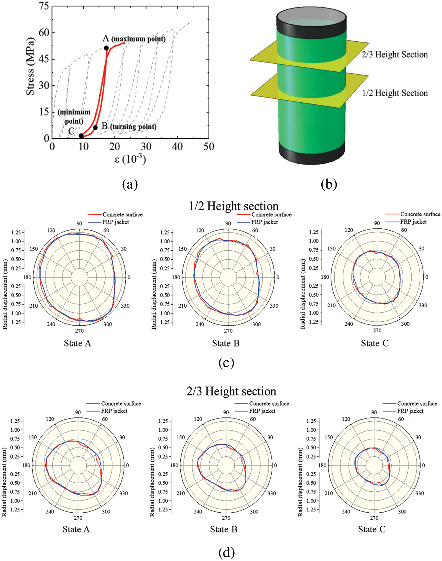
Figure 17: Radial displacements of the concrete surface and FRP jacket: (a) typical states in one cyclic process; (b) two typical selected sections; (c) radial displacements in 1/2 height section; (d) radial displacements in 2/3 height section
Furthermore, during the unloading process transitioning from state B to state C, the overall radial displacement of the concrete surface gradually becomes smaller than the radial displacement of FRP. This indicates that the compressive effect between concrete and FRP is weak during this process. Therefore, the stress-strain relationship of concrete at this stage is essentially equivalent to that of unwrapped concrete. This internal mechanism explains why there is a turning point in the cyclic unloading and reloading process of FRP-confined concrete columns. This turning point is a crucial indicator for distinguishing whether there is a noticeable compressive effect between the concrete and the FRP jacket.
4 Parametric Study of the FRP-Confined Concrete under Cyclic Compression
The CZM constitutive model proposed in this paper, compared to previous pure damage models, additionally considers plasticity and meticulously accounts for the friction effects between interfaces and potential fracture surfaces. As a result, the simulation results are closer to the experimental results. In order to better understand the internal mechanical behavior of FRP-confined concrete columns under cyclic loading, a series of parameter studies were conducted in this section. According to Section 2, the friction effect, FRP unloading stiffness, and plasticity of different contents are essential components in the constitutive models proposed model. Thus, these parameters will be investigated in the following sections (other parameters have been discussed in the previous studies [19–22]).
4.1 Friction Effect of Concrete and FRP-Concrete Interface
Different from other classical fracture models, such as the CDP model [23], the model proposed in this study can calculate friction stress in detail by considering the slip displacement in the tangential plane. Thus, the influence of the concrete inner friction was investigated by calculating the model with f = 0 and f = 0.35. Fig. 18a shows the influence of the concrete inner friction coefficient on the stress-strain curve under cyclic loading. Firstly, the inner friction of concrete would significantly affect the bearing capacity of FRP-confined concrete, which means that the friction effect contributes about half of the load-bearing capacity in such structures. Besides, it can be found that without friction, the hysteresis phenomenon in the stress-strain curve during unloading and reloading has also disappeared. This indicates that the energy dissipated during the unloading and reloading processes is primarily due to frictional energy dissipation, which results in the hysteresis phenomenon in the stress-strain curve.
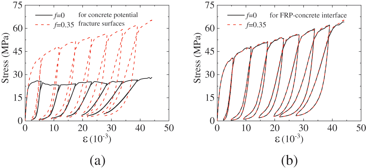
Figure 18: Influence of friction effect: (a) friction effect of concrete; (b) friction effect of FRP-concrete interface
The impact of the friction effect at the FRP-concrete interface was also investigated by calculating the model with f = 0 and f = 0.35. Fig. 18b shows the stress-strain curves with different friction coefficients. The simulation results indicate that the friction effect at the FRP-concrete interface does not influence the mechanical response of FRP-confined concrete under cyclic loading. This shows the FRP-concrete interface primarily serves to transmit normal compressive stress, with its tangential mechanical properties having minimal impact on the structure.
4.2 Plasticity of the FRP Composite Jacket
In previous literature [7,12], FRP jackets often did not consider plasticity and inter-laminar slip within the FRP. Therefore, it is necessary to conduct a detailed analysis on the influence of different constitutive models of FRP jackets on the computational results. In this study, the unloading and reloading stiffness Ere is an important parameter (in Eq. (32), this parameter decides the plastic strain) since the previous studies usually considered the FRP composite jacket as an elastic material. To investigate the influence of the FRP jacket plasticity on the cyclic loading mechanical properties of the FRP-confined concrete column, an FE model without considering the FRP jacket plasticity was calculated, and the corresponding stress-strain relation is shown in Fig. 19a.
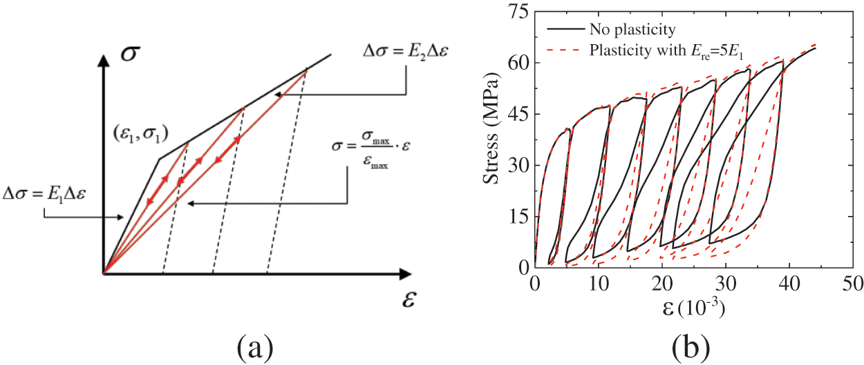
Figure 19: Influence of the FRP composite jacket plasticity: (a) the constitutive model of FRP jacket without considering plasticity; (b) stress-strain curves with different FRP jacket constitutive models
Fig. 19b shows the stress-strain curves with different FRP jacket constitutive models. When the plasticity of the FRP protective jacket is not considered, the area enclosed by the hysteresis loop of the stress-strain curve has significantly increased. This is because when the plasticity of the FRP composite jacket is not considered, it exerts greater confinement on the wrapped concrete during the unloading and reloading process. This results in larger compressive stress on the internal concrete fragments, leading to increased frictional energy dissipation in this process. Therefore, when analyzing the cyclic loading mechanical performance of FRP-confined concrete, the plasticity of the FRP composite jacket needs to be carefully considered.
4.3 Plasticity of Concrete and FRP-Concrete Interface
Compared to the damage constitutive models proposed in the previous studies [16–18], the plasticity of the interface is the most significant improvement in the constitutive models proposed in this study. Thus, the FE models without considering concrete plasticity and FRP-concrete plasticity were simulated to analyze the influence of the plasticity of these two components.
Fig. 20a shows the impact of the concrete plasticity on the cyclic loading stress-strain curve. Firstly, the stress-strain envelope curve without considering the concrete plasticity is lower than the one with plasticity considered. This is because concrete damage without considering plasticity is greater, according to the relation shown in Fig. 3b. Additionally, Since the concrete plasticity is unconsidered, the structure’s deformation must be unloaded to the origin for stress to return to zero, which is unreasonable.
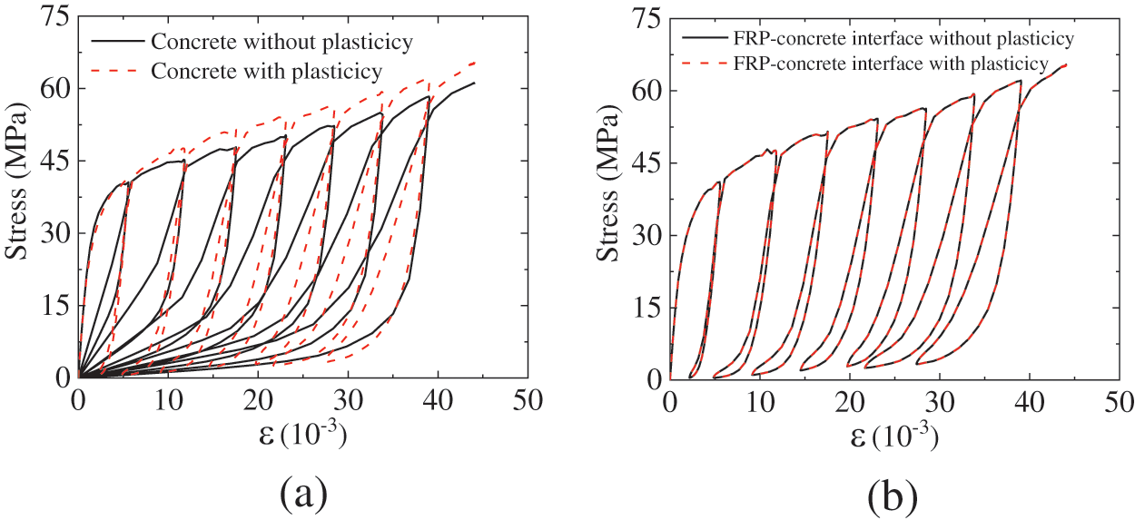
Figure 20: Influence of plasticity of different contents on the stress-strain curves: (a) influence of concrete plasticity; (b) influence of FRP-concrete interface plasticity
Fig. 20b shows the influence of FRP-concrete interface plasticity on the stress-strain curve under cyclic loading. The results show that the plasticity of the FRP-concrete interface has no impact on the cyclic loading mechanical performance of the FRP-concrete interface. As the interface is always subjected to compression during the cyclic loading process, its plasticity mainly occurs in the shear plane. The simulation results indicate that the shear behavior of the FRP-concrete interface is not crucial for such structures, and the primary role of the FRP-concrete interface is to transmit compressive stress in the normal direction. This is consistent with the conclusions obtained in Section 4.1.
In this study, a modeling method for FRP-confined concrete was developed using zero-thickness cohesive elements. These cohesive elements were used to simulate the potential fracture surfaces of concrete and the FRP-concrete interface. The CZM constitutive models were proposed to characterize the mechanical behavior of the potential fracture surfaces and FRP-concrete interface, considering the damage relation, plasticity, and friction effect. Additionally, an anisotropic plastic constitutive model was established for the FRP composite jacket. The proposed FE model was validated by performing simulations on existing compressive cyclic loading tests for plain concrete and FRP-confined concrete. By comparing the simulation results with experimental data, the proposed model successfully replicated the mechanical response of both concrete and FRP-confined concrete. The simulated stress-strain hysteresis loops showed good agreement with the experimental results. Furthermore, parametric studies were conducted to investigate the internal failure mechanism of FRP-confined concrete under cyclic loading conditions. The findings of these studies can be summarized as follows:
(1) Internal friction in concrete plays a crucial role in the mechanical performance of FRP-confined concrete. It accounts for about half of its load-bearing capacity and also determines the energy dissipation, represented by the hysteresis loop area, during cyclic loading.
(2) The plasticity of FRP composite jackets has a significant impact on the energy dissipation of FRP-confined concrete during cyclic loading. If the plasticity of FRP is not taken into account, the confinement effect on concrete would be overestimated, resulting in increased internal compression and frictional energy dissipation.
(3) Without considering the plasticity of concrete, the load-bearing capacity of concrete is reduced due to the increased damage inside the concrete compared to the one considering plasticity.
(4) The shear performance of the FRP-concrete interface has minimal impact on the structure, while the friction and plasticity of the interface have little effect on the simulation results. This suggests that the main function of the FRP-concrete interface is to transmit normal compressive stress.
Acknowledgement: None.
Funding Statement: This study was funded by the Natural Science Foundation of Fujian Province (2023J01938), the Scientific Research Startup Foundation of Fujian University of Technology (GY-Z21026).
Author Contributions: The authors confirm contribution to the paper as follows: study conception and design: Wei Zhang, analysis and interpretation of results: Mingxu Zhang; draft manuscript preparation: Mingliang Wang. All authors reviewed the results and approved the final version of the manuscript.
Availability of Data and Materials: The data that support the findings of this study are available from the corresponding author upon reasonable request.
Conflicts of Interest: The authors declare that they have no conflict of interest.
References
1. Feng P, Zhang Y, Bai Y, Ye L. Strengthening of steel members in compression by mortar-filled FRP tubes. Thin-Walled Struct. 2013;64:1–12. doi:10.1016/j.tws.2012.11.001. [Google Scholar] [CrossRef]
2. Zhao J, Teng J, Yu T, Li L. Behavior of large-scale hybrid FRP–concrete–steel double–skin tubular beams with shear connectors. J Compos Construct. 2016;20:4016015. doi:10.1061/(ASCE)CC.1943-5614.0000669. [Google Scholar] [CrossRef]
3. Wang D, Wang Z, Yu T, Li H. Seismic performance of CFRP-retrofitted large-scale rectangular RC columns under lateral loading in different directions. Compos Struct. 2018;192:475–88. doi:10.1016/j.compstruct.2018.03.029. [Google Scholar] [CrossRef]
4. Sha X, Wang Z, Feng P, Yang J. Axial compressive behavior of square-section concrete columns transversely reinforced with FRP grids. J Compos Construct. 2020;24:4020028. doi:10.1061/(ASCE)CC.1943-5614.0001025. [Google Scholar] [CrossRef]
5. Ye Y, Liang S, Feng P, Zeng J. Recyclable LRS FRP composites for engineering structures: current status and future opportunities. Compos Part B: Eng. 2021;212:108689. doi:10.1016/j.compositesb.2021.108689. [Google Scholar] [CrossRef]
6. Dong Z, Han T, Zhang B, Zhu H, Wu G, Wei Y, et al. A review of the research and application progress of new types of concrete-filled FRP tubular members. Constr Build Mater. 2021;312:125353. doi:10.1016/j.conbuildmat.2021.125353. [Google Scholar] [CrossRef]
7. Dai J, Bai Y, Teng J. Behavior and modeling of concrete confined with FRP composites of large deformability. J Compos Construct. 2011;15:963–73. doi:10.1061/(ASCE)CC.1943-5614.0000230. [Google Scholar] [CrossRef]
8. Wu G, Lü Z, Wu Z. Strength and ductility of concrete cylinders confined with FRP composites. Constr Build Mater. 2006;20:134–48. doi:10.1016/j.conbuildmat.2005.01.022. [Google Scholar] [CrossRef]
9. Zhou Y, Zheng Y, Sui L, Xing F, Hu J, Li P. Behavior and modeling of FRP-confined ultra-lightweight cement composites under monotonic axial compression. Compos Part B: Eng. 2019;162:289–302. doi:10.1016/j.compositesb.2018.10.087. [Google Scholar] [CrossRef]
10. Dang Z, Feng P, Yang J, Zhang Q. Axial compressive behavior of engineered cementitious composite confined by fiber-reinforced polymer. Compos Struct. 2020;243:112191. doi:10.1016/j.compstruct.2020.112191. [Google Scholar] [CrossRef]
11. Liao J, Zeng J, Zhu G, Zheng Y, Ma G, Zhang L. FRP-confined concrete columns with a stress reduction-recovery behavior: a state-of-the-art review, design recommendations and model assessments. Compos Struct. 2023;321:117313. doi:10.1016/j.compstruct.2023.117313. [Google Scholar] [CrossRef]
12. Bai Y, Dai J, Teng J. Cyclic compressive behavior of concrete confined with large rupture strain FRP composites. J Compos Construct. 2014;18:4013025. doi:10.1061/(ASCE)CC.1943-5614.0000386. [Google Scholar] [CrossRef]
13. Teng J, Lam L, Lin G, Lu J, Xiao Q. Numerical simulation of FRP-jacketed RC columns subjected to cyclic and seismic loading. J Compos Construct. 2016;20:4015021. doi:10.1061/(ASCE)CC.1943-5614.0000584. [Google Scholar] [CrossRef]
14. Isleem H, Wang Z, Wang D, Smith S. Monotonic and cyclic axial compressive behavior of CFRP-confined rectangular RC columns. J Compos Construct. 2018;22:4018023. doi:10.1061/(ASCE)CC.1943-5614.0000860. [Google Scholar] [CrossRef]
15. Ispir M, Dalgic K, Ilki A. Cyclic compressive behavior of hybrid FRP-confined concrete. J Compos Construct. 2021;25:4021045. doi:10.1061/(ASCE)CC.1943-5614.0001156. [Google Scholar] [CrossRef]
16. Zhang W, Huang Y. Three-dimensional numerical investigation of mixed-mode debonding of FRP-concrete interface using a cohesive zone model. Constr Build Mater. 2020;350:128818. doi:10.1016/j.conbuildmat.2022.128818. [Google Scholar] [CrossRef]
17. Huang Y, Zhang W, Liu X. Assessment of diagonal macrocrack-induced debonding mechanisms in FRP-strengthened RC beams. J Compos Construct. 2020;26:4022056. doi:10.1061/(ASCE)CC.1943-5614.0001255. [Google Scholar] [CrossRef]
18. Zhang W, Kang S, Huang Y, Liu X. Behavior of reinforced concrete beams without stirrups and strengthened with basalt fiber–reinforced polymer sheets. J Compos Construct. 2023;27:4023007. doi:10.1061/JCCOF2.CCENG-4082. [Google Scholar] [CrossRef]
19. López C, Carol I, Aguado A. Meso-structural study of concrete fracture using interface elements. I: numerical model and tensile behavior. Mater Struct. 2008;41:583–99. doi:10.1617/s11527-007-9314-1. [Google Scholar] [CrossRef]
20. Razaqpur A, Lamberti M, Ascione F. A nonlinear semi-analytical model for predicting debonding of FRP laminates from RC beams subjected to uniform or concentrated load. Construct Building Mat. 2019;233:117838. doi:10.1016/j.conbuildmat.2019.117838. [Google Scholar] [CrossRef]
21. Razaqpur A, Lamberti M, Ascione F. Debonding evolution in nonlinear FRP-retrofitted RC beams with cohesive interface. Compos Struct. 2020;236:111858. doi:10.1016/j.compstruct.2020.111858. [Google Scholar] [CrossRef]
22. Zhang W, Tang Z, Yang Y, Wei J. Assessment of FRP–concrete interfacial debonding with coupled mixed-mode cohesive zone model. J Compos Construct. 2021;25:4021002. doi:10.1061/(ASCE)CC.1943-5614.0001114. [Google Scholar] [CrossRef]
23. Simulia. Abaqus Analysis User’s Guide, Version 6.14: Dassault Systemes Providence, RI; 2014. [Google Scholar]
24. Ozcelik R. Cyclic testing of low-strength plain concrete. Mag Concr Res. 2015;67:379–90. doi:10.1680/macr.14.00234. [Google Scholar] [CrossRef]
Cite This Article
 Copyright © 2024 The Author(s). Published by Tech Science Press.
This work is licensed under a Creative Commons Attribution 4.0 International License , which permits unrestricted use, distribution, and reproduction in any medium, provided the original work is properly cited.
 Downloads
 Citation Tools