
 Submit a Paper
 Propose a Special lssue
 Open Access
ARTICLE

Shield Excavation Analysis: Ground Settlement & Mechanical Responses in Complex Strata
1 CCCC Rail Transit Branch, Beijing, 101300, China
2 School of Civil Engineering, Fujian University of Technology, Fuzhou, 350118, China
* Corresponding Author: Wei Zhang. Email:
(This article belongs to the Special Issue: Health Monitoring and Rapid Evaluation of Infrastructures)
Structural Durability & Health Monitoring 2024, 18(3), 341-360. https://doi.org/10.32604/sdhm.2024.047405
Received 04 November 2023; Accepted 19 January 2024; Issue published 15 May 2024
 View Full Text
 Download PDF
Abstract
This study delves into the effects of shield tunneling in complex coastal strata, focusing on how this construction method impacts surface settlement, the mechanical properties of adjacent rock, and the deformation of tunnel segments. It investigates the impact of shield construction on surface settlement, mechanical characteristics of nearby rock, and segment deformation in complex coastal strata susceptible to construction disturbances. Utilizing the Fuzhou Binhai express line as a case study, we developed a comprehensive numerical model using the ABAQUS finite element software. The model incorporates factors such as face force, grouting pressure, jack force, and cutterhead torque. Its accuracy is validated against field monitoring data from engineering projects. Simulations were conducted to analyze ground settlement and mechanical changes in adjacent rock and segments across five soil layers. The results indicate that disturbances are most significant near the excavation zone of the shield machine, with a prominent settlement trough forming and stabilizing around 2.0–3.0 D from the excavation. The excavation face compresses the soil, inducing lateral expansion. As grouting pressure decreases, the segment experiences upward buoyancy. In mixed strata, softer layers witness increased cutting, intensifying disturbances but reducing segment floatation. These findings offer valuable insights for predicting settlements, ensuring segment and rock safety, and optimizing tunneling parameters.Keywords
As urban populations surge and urbanization accelerates, traffic congestion intensifies, prompting the adoption of underground tunnels as a prevalent solution in contemporary urban transportation to address this challenge. Among various excavation techniques, the shield method is frequently employed due to its rapid pace, minimal disruption, and ease of construction [1–6]. However, this method faces challenges in diverse geological conditions such as fault fracture zones, saturated sandy layers, and heterogeneous strata, particularly in coastal areas with complex strata. This complexity leads to intricate interactions among the strata, surrounding rock, and tunnel segments during shield construction, potentially resulting in diverse outcomes. Therefore, studying the variation in ground surface settlement and mechanical properties of the surrounding rock and segments in complex coastal strata is necessary.
Numerous scholars have investigated the impact of tunneling on both ground surface settlement and the mechanical attributes of the surrounding rock and tunnel segments. For instance, Mo et al. [7] examined the effects of jacking forces, grouting pressures, and earth pressures on tunnel segments, refining the head design of the shield machine. Wang et al. [8] employed a wavelet kernel (wsRVM) to forecast tunnelling-induced ground surface settlement, demonstrating its practical application. Ye et al. [9] explored the effects of pressure from a tail brush on tunnel segments, offering insights beneficial for construction. Li et al. [10] utilized the finite element method to probe the influence of the dilation angle on support pressure limits, failure zones, and partial failure ratios, introducing a log-spiral mechanism to enhance face instability analysis.
Other notable works include Gan et al.’s two-stage analytical approach for predicting asymmetrical ground settlement due to tunneling [11]; Katebi et al.’s ABAQUS-based study on the interplay of tunnel depth, building characteristics, and ground stratification for optimal lining design [1]; and Liu et al.’s examination of the mechanical response in the cobble stratum and the implications of the cutterhead opening ratio on surface settlement and shield attributes [12]. Zhao et al. [13] and Zhang et al. [14] focused on computational methodologies and pressure models, respectively, to evaluate various construction factors. Several researchers, including Huang et al. [15,16], Liu et al. [17], Guo et al. [18], Jia et al. [19], and Cui et al. [20], investigated the effects of grouting, stratum properties, and shield parameters on various aspects of tunneling.
Notably, many researchers have studied the settlement of the ground surface, horizontal displacement of strata, and mechanical properties of the surrounding rock and segments using the FE method. However, most of the existing studies are based on single soil strata to investigate influential factors or effects of single shield parameters, with a primary focus on the deformation of the soil or segment. Therefore, there is an urgent need to study the characteristics of the soil, surrounding rock, and segment caused by excavation and the shielding parameters in complex coastal strata, where the shield excavation face passes through different soil layers simultaneously.
In summary, this study used a shield tunnel in a segment of the Fuzhou Metro Binhai Express Line as the engineering context and formulated a numerical model using ABAQUS software. This model was validated using monitoring data, and the research delves into the impacts of grouting pressure, face pressure, cutterhead torque, and jack force on the soil characteristics, as well as the mechanical properties of the surrounding rock and tunnel segment. The conclusion examines the effects of five distinct complex strata on the soil characteristics and mechanical attributes of both the surrounding rock and tunnel segments.
The Fuzhou Metro Binhai Express Line passes through a stratum characterized by a diverse range of composite soil layers, with isolated stones being a prevalent feature. A noticeable variation in the stratum is observed along the section from the airport station to the intermediate ventilation shaft, covering a distance of 3,360 m. This section displays a maximum vertical gradient of 28° and a minimal turning radius of 1,700 m. For this specific stretch, an EPB Shield Machine is employed, with specifications including an outer diameter of 8.3 m, an inner diameter of 7.5 m, a width of 1.8 m, and a thickness of 0.4 m. The shield tail diameter is noted at 8.56 m, while the burial depth of the tunnel varies between 8.44 and 24.30 m. A graphical representation of the geological context is provided in Fig. 1. Table 1 details the distribution of the five selected soil layers, determined based on the geology of the section. This categorization aims to enhance the understanding of soil settlement mechanics within the composite layers during shield construction.

Figure 1: Geological situation statistical map

During the shield tunneling process, significant disturbances to the strata are primarily induced by face pressure and grouting pressure at the shield’s tail. Additionally, the effects of jack force and cutterhead torque require careful consideration. To comprehensively analyze these factors, a detailed shield tunnel excavation model was developed using the finite element software ABAQUS, enabling a meticulous simulation of the shield tunneling process. This model facilitated the examination of settlement mechanisms in diverse complex strata.
In constructing the model, a burial depth equivalent to 2.0 D was considered, where D represents the diameter of the shield tunneling machine, encompassing both the segment diameter and the grouting layer thickness. The stratigraphic distribution of the model is depicted in Fig. 2. To mitigate the impact of boundary conditions, the model boundary was set 3.0–5.0 D away from the tunnel excavation location. The model size was defined as 52 m × 60 m × 54 m for the simulation of the construction process. Each excavation increment corresponded to a segment width of 1.8 m, and a cumulative total of 30 rings were excavated. Constraints were applied to prevent normal displacement at the base and sides of the model, while the top surface remained unconstrained and served as a free surface. The mesh of the FEM model is shown in Fig. 3, and the mesh size was determined from 1 to 4 m. To ensure calculation accuracy and improve calculation efficiency, the mesh size closer to the shield tunnel was smaller, and the mesh size farther away from the shield tunnel was larger.

Figure 2: Modeled stratigraphic distribution map

Figure 3: Schematic diagram of the mesh of FEM model
The model based on some assumptions, as follows:
(1) The friction force between the shield shell and the formation was not considered.
(2) The water table of the coastal strata was not considered.
(3) The hardening process of grouting slurry was not considered.
The soil was characterized using the Mohr-Coulomb constitutive model, with mechanical parameters outlined in Table 2 based on the engineering geological survey report. The shield machine was simulated as an elastic homogeneous shell. The pipe segments and grouting layer were modeled as uniform circular rings, interconnected in a coupled manner. Material parameters for the model are detailed in Table 3.


The main loads of the tunneling structures during shield tunneling as follows:
(1) Face pressure
During EPB shield tunneling, the pushing and cutting action of the cutterhead on the forward soil can lead to either uplift or settlement deformation of the soil. However, for the purposes of this study, idealized conditions were assumed. A consistent and uniformly distributed force was applied across each excavation face. The magnitude of this force was determined based on the excavation parameters of the shield tunneling machine derived from actual construction scenarios
(2) Cutterhead torque
The cutterhead’s action on the soil introduces disturbances in its immediate vicinity. In this model, torque was applied to the excavation surface of the soil, with its magnitude determined by referencing the excavation parameters of the shield tunneling machine used in real-world construction.
(3) Grouting pressure
During shield construction, the actual excavation radius of the shield machine exceeded the radius of the pipe segment. As a result, cement slurry was employed to fill the space between the soil and pipe segments to manage surface settlement and ensure the watertightness of the tunnel. However, it is important to note that the pressure exerted during the grouting process affects both the soil and pipe segments, introducing a secondary disturbance.
(4) Jack force
As the shield machine advanced, it applied a jacking force to the assembled segments, leading to disturbances in both the segments and the adjacent rock. In the model, this jack force is conceptualized as a uniformly distributed pressure across the entire cross-section of the segments, closely resembling the force exerted by multiple jacks in practical applications.
The shield excavation simulation was performed using ABAQUS’s integrated geostress balance, supplemented by the model change function. The main steps were as follows:
(1) Geo-stress balance: After geo-stress balance, the maximum displacement of the soil reaches the order of 10−6, which is close to zero.
(2) Similar to the actual project, the soil was excavated at a depth of 1.8 m per ring. During excavation, face pressure and cutterhead torque were applied to the excavation surface, whereas a jack force was applied to the assembled pipe segment. Grouting pressure was applied to the outer surface of the pipe segment and soil, and the grouting layers were arranged synchronously. The model did not consider the hardening process of the grouting slurry.
(3) Apply face pressure and cutter head torque to the excavation surface of the next ring of soil, remove the front ring of soil, apply load, activate the shield shell, apply jack force to the newly added pipe segment, apply grouting pressure to the outer surface of the pipe segment and soil, and synchronously arrange the grouting layer.
(4) The above steps are repeated until the excavation is completed. A schematic of the excavation model is shown in Fig. 4.

Figure 4: Schematic diagram of model excavation
4 Results Analysis and Discussion
The soil layer chosen for the analysis of the model results is the largest soil layer through which the shield tunneling machine passes during the actual construction process. Specifically, it corresponds to the soil layer identified as Condition 2 in this study, as outlined in Table 1. Subsequent to selecting this soil layer, the following text analyzes the surface settlement mechanism and various parameters during shield construction. The model load values were derived from the shield tunneling parameters at the project site, as presented in Table 4.

4.1 Analysis of Settlement of Ground Surface
Ground settlement serves as a crucial monitoring and evaluation index during shield excavation. To observe the changes in ground settlement above the tunnel during shield tunneling, Fig. 5 illustrates the variation in ground settlement. It is evident that as the shield tunneling machine progresses through a certain number of rings, substantial settlement occurs in the ring and the surrounding rock. With the continuous tunneling of the shield machine, the surface settlement of the soil continues to increase.

Figure 5: Ground surface settlement curves above the tunnel
To analyze the influence area of shield tunneling, the ground settlement of the soil at the middle section of the tunnel, specifically the 15th ring section in the model, was analyzed. The ground settlement in the middle section of the tunnel is shown in Fig. 6. It can be observed that with the tunneling of the shield machine, before reaching the middle section, owing to the heavy weight of the shield machine and the soft soil layer where the shield machine was located, the surface of the middle section had a slight settlement, and the settlement range was small.

Figure 6: Ground surface settlement curves in the middle section of the tunnel
Observations indicate that, prior to reaching the middle section, the surface had experienced slight settlement due to the heavy weight of the shield machine and the soft soil layer in its location. The settlement range during this phase was relatively small.
Upon the arrival of the shield machine at the middle section, settlement grooves began to appear on the surface due to the machine’s weight. These grooves were approximately distributed within 10 meters on both sides of the tunnel excavation axis, with the maximum settlement value directly above the tunnel. As the shield tunneling machine traversed the middle section, the disappearance of grouting pressure led to a more noticeable surface settlement. The settlement trough widened and deepened, and due to the aggravation of soil settlement in the settlement tank area and boundary condition limitations, soil compression occurred on both sides of the settlement tank, resulting in increased soil uplift. By the time the shield tunneling machine reached the 25th ring, the surface settlement value of the middle section tended to stabilize. The approximate influence range of shield tunneling was found to be 18 m (between 2.0 and 3.0 D). After shield tunneling, the maximum settlement of the middle section was 10.06 mm, and the maximum uplift was 5.69 mm.
To investigate the settlement patterns in different strata above the tunnel, Fig. 7 illustrates the vertical displacement of the soil at various depths after the completion of 30 rings of shield driving. The results reveal that the settlement of the soil at each layer above the central axis of the tunnel demonstrates coordinated deformation. The impact of the soil layer becomes more pronounced the closer it is to the tunnel excavation depth, leading to more noticeable settlement and uplift. Additionally, to explore the settlement laws of different strata in the section direction, Fig. 8 displays the vertical displacement of soil at different depths in the middle section after the completion of 30 rings of shield tunneling. Similar patterns can be observed, emphasizing the coordinated settlement and uplift of the soil in different strata.

Figure 7: Ground settlement curves of tunnel center axis

Figure 8: Ground settlement curves in the middle section of the tunnel
In Fig. 9, the horizontal displacement of the stratum at 8 m on the right side of the excavation axis in the middle section of the tunnel at different depths is presented. Observations indicate that, when the cutterhead has not yet reached the middle section, the forward pushing of the face force and the application of the cutterhead torque result in a certain extrusion deformation of the soil, displaying an outward expansion trend.

Figure 9: Horizontal displacement of strata 8 m to the right of the tunnel axis
Upon the cutterhead reaching the middle section, the influence of grouting pressure leads to a sudden increase in the horizontal displacement of the stratum, most notably at the excavation center, where the maximum horizontal displacement occurs. Simultaneously, due to the outward expansion of the central part of the stratum, the upper and lower soils in the central part exhibit a slight reverse horizontal displacement. This observation aligns with simulation results reported in the literature [22]. When the cutterhead passes through the middle section, owing to the loss of the soil stratum, and the stiffness of the segment and grouting layer is less than that of the shield shell, the horizontal displacement of the stratum continues to increase, but the rate of increase slows until the tunnel excavation is completed.
To validate the accuracy of the finite-element shield construction model, construction monitoring data for the same soil layer were selected for comparison and verification, ensuring the rationality of the simulation results.
Monitoring of the ground surface at the airport station of the Fuzhou Metro Binhai Express, in the middle air shaft section, primarily involves the transverse settlement monitoring of the ground surface. In this model, with 30 excavation rings and the corresponding soil layer range of 1–200 ring soil layers on the left line, the monitoring section data was compared with the simulation results for the middle section. The distance between the shield machine and the section was judged based on the daily excavation progress of the shield machine. Fig. 10 provides a schematic diagram of the monitoring section, while Fig. 11 illustrates the comparison results.

Figure 10: The schematic diagram of the monitoring section

Figure 11: Comparison of lateral ground settlement
Upon reviewing the comparison results, it is evident that the variation trends of the simulation and monitoring values are largely consistent near the excavation axis. However, the monitoring value at the position of the maximum settlement value exhibits a certain eccentricity compared to the simulation value. On both sides of the settlement trough, the uplift of the simulated value is noticeable, as the contact stiffness on both sides of the soil was smaller in the actual project. Differences between monitored and simulated values may arise due to the adjustment of tunneling parameters in real-time during shield construction based on the actual conditions.
The above comparison results reasonably verify the rationality of the finite element model in this study.
4.1.1 Influence of Grouting Pressure
The impact of grouting pressure on the soil strata is summarized in Table 5. As the grouting pressure increases, there is a gradual linear increase in both the maximum ground surface settlement and horizontal displacement of the strata. The respective maximum ground surface settlements for grouting pressures of 150, 200, 250, 300, and 350 kPa were −3.85, −3.91, −3.99, −4.08, and −4.20 mm. The corresponding maximum horizontal displacements of the strata with grouting pressures of 150, 200, 250, 300, and 350 kPa were 5.44, 5.51, 5.58, 5.66, and 5.76 mm, respectively. The grouting pressure exhibited little influence on the ground surface settlement and horizontal displacement of the strata.

4.1.2 Influence of the Cutterhead Torque
The influence of the cutterhead torque on the soil strata is shown in Table 6. With an increase in the cutterhead torque, the maximum ground surface settlement and horizontal displacement of the strata gradually increased. The corresponding maximum ground surface settlement with cutterhead torque of 1000, 1500, 2000, 2500 and 3000 kN•m are −3.66, −3.78, −3.99, −4.10, and −4.23 mm, respectively. The corresponding maximum horizontal displacement of strata with grouting pressure of 1000, 1500, 2000, 2500, and 3000 are 5.50, 5.52, 5.58, 5.62, and 5.78 mm, respectively. The cutterhead torque had minimal influence on the ground surface settlement and horizontal displacement of the strata.

4.1.3 Influence of the Face Pressure
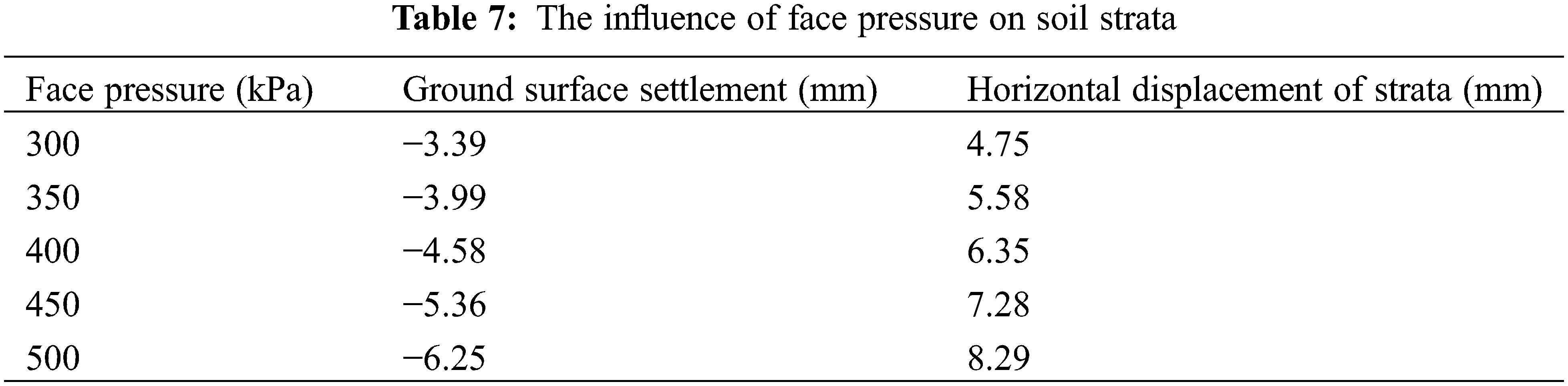
The impact of face pressure on the soil strata is outlined in Table 7. As the face pressure increases, there is a gradual rise in both the maximum ground surface settlement and horizontal displacement of the strata. The respective maximum ground surface settlements for face pressures of 300, 350, 400, 450, and 500 were −3.39, −3.99, −4.58, −5.36, and −6.25 mm, respectively. Correspondingly, the maximum horizontal displacements of the strata with face pressures of 300, 350, 400, 450, and 500 kPa were 4.75, 5.58, 6.35, 7.28, and 8.29 mm, respectively. It is evident that face pressure significantly influences both the ground surface settlement and horizontal displacement of the strata.
4.1.4 Influence of the Jack Force
The influence of the jack force on the soil strata is detailed in Table 8. As the jack force increases, there is a gradual elevation in both the maximum ground surface settlement and horizontal displacement of the strata. The respective maximum ground surface settlements for jack forces of 1000, 1500, 2000, 2500, and 3000 kPa were −1.36, −2.43, −3.99, −5.62, and −7.50 mm, respectively. Correspondingly, the maximum horizontal displacements of the strata with jack forces of 1000, 1500, 2000, 2500, and 3000 kPa were 5.44, 5.51, 5.58, 5.66, and 5.76 mm, respectively. Evidently, the jack force significantly influences both the ground surface settlement and horizontal displacement of the strata.

Based on the above analysis, to reduce the disturbance of soil caused by shield tunneling construction, it is recommended to adjust the face pressure and jack force reasonably according to the excavation strata and adjust the grouting pressure in real time to effectively control the disturbance amplitude of the soil.
4.2 Analysis of Deformation of Shield Tunnel Segment
Different shield tunneling parameters inevitably result in various deformations in the shield segment, with key parameters being the grouting pressure and jack force. Both loads are directly applied to the segment, while the other two loads are applied to the soil at long distances.
The model comprises a total of 30 excavation rings. To assess the deformation of the shield tunnel segment, the vertical displacement of the 15th segment top area and the horizontal displacement of the 15th segment right area are considered as evaluation indices. Fig. 12 provides a schematic diagram of the segment, with the direction indicated by arrows representing the positive displacement direction.

Figure 12: Schematic diagram of the segment
4.2.1 Influence of Grouting Pressure
Fig. 13 shows the deformation of the 15th segment during excavation at different grouting pressures. The deformation of the segment increased significantly as the excavation process progressed. Figs. 13a and 13b show that, with an increase in the grouting pressure, the deformation of the segment increases. The corresponding maximum vertical displacement of segment with grouting pressure of 150, 200, 250, 300, and 350 kPa are 6.73, 6.85, 6.98, 7.10, and 7.23 mm, respectively. The corresponding maximum horizontal displacement of segment with grouting pressure of 150, 200, 250, 300, and 350 kPa are −0.75, −0.81, −0.87, −0.93, and −0.99 mm, respectively. This is mainly because the greater the grouting pressure is, the greater is the disturbance to the segment when it disappears.

Figure 13: The deformation of the 15th segment with different grouting pressure; (a) vertical displacement; (b) horizontal displacement
4.2.2 Influence of the Jack Force
Fig. 14 shows the deformation of the 15th segment during the excavation under different jack forces. The deformation of the segment increased significantly as the excavation process progressed. Figs. 14a and 14b show that the deformation of the segment increased with an increase in the jack force. The corresponding maximum vertical displacements of the segment with jack forces of 1000, 1500, 2000, 2500, and 3000 kPa were 5.38, 5.72, 6.85, 8.81, and 11.53 mm, respectively. The corresponding maximum horizontal displacement of segment with jack force of 1000, 1500, 2000, 2500, and 3000 kPa are −0.49, −0.67, −0.93, −1.24 and −1.58 mm, respectively. The main reason for this is that the greater the jack force, the greater is the disturbance to the segment when it disappears.

Figure 14: The deformation of the 15th segment with different jack force; (a) vertical displacement; (b) horizontal displacement
A larger grouting pressure and jack force are not conducive to protecting segment safety. The shield parameters should be adjusted to reduce the floating of pipe segments.
4.3 Analysis of the Mechanical Properties of Surrounding Rock
The surrounding rock is inevitably affected by the tunnel excavation and damage [23]. Therefore, the stability of surrounding rocks was investigated in this study. The horizontal displacement and shear stress were considered as the assessment indices. The positions of the assessment indices were defined as the semicircular soil layer 7 m to the right of the tunnel axis in the middle section of the tunnel, as shown in Fig. 15. The horizontal displacement curves and shear stress of the semicircular soil layer 7 m to the right of the tunnel axis with excavation are shown in Figs. 16 and 17, respectively.

Figure 15: Schematic diagram of the position and angle of surrounding rock

Figure 16: Horizontal displacement of surrounding rock

Figure 17: Horizontal shear stress of surrounding rock
Fig. 16 illustrates that with an increase in tunnel excavation, the horizontal displacement of the surrounding rock similarly increases. The corresponding maximum horizontal displacements of the surrounding rock with excavating rings 5, 10, 15, 20, 25, and 30 were 0.40, 1.35, 10.35, 12.34, 15.06, and 15.56 mm, respectively. Notably, there is a rapid increase in this value when 15 rings are excavated, likely due to the shield machine excavating the middle section of the tunnel. Fig. 17 demonstrates that with an increase in tunnel excavation, the horizontal shear stress of the surrounding rock increases and decreases between excavating rings 20 and 30. The corresponding maximum horizontal shear stresses of the surrounding rock with excavating rings 5, 10, 15, 20, 25, and 30 are −0.25, −2.62, −27.30, −27.32, −21.32, and −19.52 kPa. The horizontal shear stresses of the upper and lower soil layers exhibit different changes, with the soil layer division line as the centerline. The horizontal shear stress of the surrounding rock is discontinuous. When the two layers of soil on the excavation surface differ, the excavation generates greater lateral shear stress on the softer soil layer, causing more cutting and disturbance, thus impacting the surrounding rock.
The analysis indicates that tunnel excavation significantly influences the horizontal displacement and shear stress, emphasizing the need to select appropriate shield excavation parameters to ensure tunnel safety. The impact of closer parameters, such as cutterhead torque and face pressure, on the surrounding rock was also studied.
4.3.1 Influence of the Cutterhead Torque
The cutterhead torque is usually applied to the soil or rock in front of a shield machine. These values were defined according to the mechanical properties of the soil or rock. In order to study the effect of cutterhead torque on the horizontal displacement and shear stress of surrounding rock, the cutter torque of 1000, 1500, 2000, 2500, and 3000 kN•m are considered. The variations in the horizontal displacement and shear stress of the surrounding rock with the cutterhead torque are shown in Fig. 18.

Figure 18: The deformation of strata 7 m to the right of tunnel axis with different cutterhead torque; (a) horizontal displacement; (b) horizontal sheer stress
Fig. 18 shows that the cutterhead torque has little effect on the surrounding rock. The main reason is that the deformation capacity of the soil is strong, which can effectively share the torque applied by the cutterhead; therefore, the disturbance to the surrounding rock is very small.
4.3.2 Influence of the Face Pressure
Face pressure is applied to the excavation face to control ground surface settlement and ensure the stability of the excavation surface. However, this action compresses the soil near the excavation face, leading to an outward expansion trend. Facial pressures of 300, 350, 400, 450, and 500 kPa were utilized to investigate the impact of face pressure on the mechanical properties of the surrounding rock.
Fig. 19 reveals that face pressure has a substantial impact on the horizontal displacement and shear stress of the surrounding rock. It is observed that horizontal displacement increases with face pressure. This occurs because a higher face pressure inevitably compresses the surrounding rock, resulting in significant deformation. As face pressure increases, the shear stress of the softer soil gradually rises, while the shear stress of the harder soil decreases.
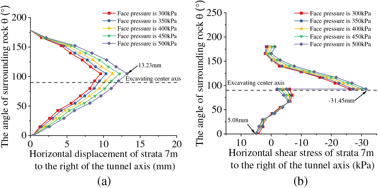
Figure 19: The deformation of strata 7 m to the right of tunnel axis with different face pressure; (a) horizontal displacement; (b) horizontal sheer stress
The simulation results suggest that a higher face force contributes to the stability of the surrounding rock. Therefore, it is crucial to adjust the face force as much as possible to minimize over excavation and prevent damage.
5 Analysis of Soil, Surrounding Rock and Segment in Complex Strata
Building on the parameter analysis above, the single-factor analysis method was employed to further analyze the characteristics of soil, surrounding rock, and shield segment construction under five different working conditions of soil layers (as listed in Table 2) while being subjected to the control model load outlined in Table 4. The shield construction traversed various soil layers, with the dividing line of different soil layers defined as the transverse central axis of the tunnel, illustrated in the S2 and S3 soil layers in Fig. 2.
5.1 Analysis of Strata on Settlement and Horizontal Displacement
Fig. 20 displays the surface settlements of the middle section under different operating conditions. It is evident that when the elastic modulus of the upper soil layer is significantly greater than that of the lower soil layer, the depth of the settlement trough is shallow, and an overall phenomenon of uplift occurs. Conversely, when the elastic modulus of the upper soil layer is less than that of the lower soil layer, the depth of the settlement trough is generally the same.

Figure 20: Ground surface settlement curves in the middle section of the tunnel in different conditions
5.2 Analysis of Deformation on Mechanical Properties of Surrounding Rock
Fig. 21 illustrates the horizontal displacement of the strata located 7 m to the right of the tunnel axis in the middle section surrounding the rock under different working conditions, with detailed conditions listed in Table 1. When the elastic modulus of the upper soil layer is smaller than that of the lower soil layer, the horizontal displacement of the surrounding rock is notably greater than that of the lower soil layer, as depicted in Fig. 21a. In cases where the upper and lower layers differ, the softer soil layer experiences greater lateral shear stress, resulting in more significant deformation, as shown in Fig. 21b.

Figure 21: The deformation of strata 7 m to the right of tunnel axis with different working conditions in the middle section; (a) horizontal displacement; (b) horizontal sheer stress
5.3 Analysis of Deformation on Mechanical Properties of Segment
Fig. 22 depicts the deformation of the 15th segment during excavation under different conditions. It is observed that when the elastic modulus of the upper soil layer is greater than that of the lower soil layer, both the vertical and horizontal displacement of the pipe segment increase significantly. The primary reason for this is the more pronounced rebound of the soil layer after the completion of excavation and the arrangement of the pipe segments.

Figure 22: The deformation of the 15th segment with different working conditions; (a) vertical displacement; (b) horizontal displacement
Based on these results, when there is a significant difference in the properties of the upper and lower soil layers in the area where the excavation surface is located, the shield machine may cause greater disturbance to the softer soil layers, thereby increasing the impact on the deformation of the surrounding rock and segments. Consequently, in this soil layer, excavation parameters should be adjusted based on actual conditions to mitigate the risk of damage.
This study focuses on a shield tunnel segment of the Fuzhou Metro Binhai Express Line as its engineering context. A numerical model, validated using ABAQUS software and field monitoring data, was developed to investigate the impacts of grouting pressure, face pressure, cutterhead torque, and jack force on soil characteristics and mechanical properties of the surrounding rock and segment. The study also evaluates the influence of five distinct complex strata on these parameters. The key findings are summarized as follows:
(1) Excavation using the shield technique induces noticeable disturbances and deformations in the ground soil. Closer proximity to the excavation site results in heightened disturbances, and a rebound in the soil is observed after the machine passes through.
(2) A pronounced settlement trough appears on the surface as the machine approaches the excavation site, covering an area of 10 m on either side of the excavation axis. Peak settlement directly above the tunnel reaches −10.06 mm. Subsequent to the machine’s transit, the surface settlement accentuates and the peck value is 5.69 mm, concomitant with heightened soil heave at the sides, a result of soil compression and settlement. Once the shield machine was at a distance of 2.0–3.0 D from the excavation, the surface settlement at the central section stabilized.
(3) Simulation analyses incorporating parameters like excavation face force, grouting pressure, jack force, and cutterhead torque indicate that an upsurge in excavation face force and jack force magnifies surface settlement and strata’s horizontal displacement, escalating soil disturbance. And when the cutterhead torque increases by three times, the ground surface settlement increases by 15% and the horizontal displacement of strata increases by 5%. During shield construction, it is feasible to modulate the face and jack forces according to the strata being excavated, whilst concurrently managing the grouting pressure.
(4) Elevated grouting pressures and jack forces are advantageous, mitigating segment flotation after grouting pressure cessation. Higher face pressure enhances the stability of the surrounding rock.
(5) When the tunnel intersects various soil layers and the elastic modulus of the upper soil layer is significantly lower than that of the lower layer, the settlement trough remains shallow, predominantly uplifting the soil layer. Low elastic modulus in either upper or lower layers may exacerbate disturbances in softer layers, amplifying deformation in neighboring rock and segments. Real-time adjustments to tunneling parameters are advisable in operational engineering contexts.
Acknowledgement: None.
Funding Statement: The authors received no specific funding for this study.
Author Contributions: The authors confirm contribution to the paper as follows: study conception and design: Baojun Qin, Guangwei Zhang; data collection: Wei Zhang; analysis and interpretation of results: Baojun Qin; draft manuscript preparation: Guangwei Zhang. All authors reviewed the results and approved the final version of the manuscript.
Availability of Data and Materials: The data that support the findings of this study are available from the corresponding author upon reasonable request.
Conflicts of Interest: The authors declare that they have no conflicts of interest to report regarding the present study.
References
1. Katebi, H., Rezaei, A. H., Hajialilue-Bonab, M., Tarifard, A. (2015). Assessment the influence of ground stratification, tunnel and surface buildings specifications on shield tunnel lining loads (by FEM). Tunnelling and Underground Space Technology, 49, 67–78. https://doi.org/10.1016/j.tust.2015.04.004. [Google Scholar] [CrossRef]
2. Zhang, M., Li, S., Li, P. (2020). Numerical analysis of ground displacement and segmental stress and influence of yaw excavation loadings for a curved shield tunnel. Computers and Geotechnics, 118, 103325. https://doi.org/10.1016/j.compgeo.2019.103325. [Google Scholar] [CrossRef]
3. Liu, L., Wang, X., Li, C., Tian, Z. (2023). Jamming of the double-shield tunnel boring machine in a deep tunnel in Nyingchi, Tibet Autonomous Region, China. Tunnelling and Underground Space Technology, 131, 104819. https://doi.org/10.1016/j.tust.2022.104819. [Google Scholar] [CrossRef]
4. Zheng, G., Wang, R., Lei, H., Zhang, T., Fan, Q. (2023). Load-transfer-associated settlements of a piled building during shield tunnelling in soft ground. Tunnelling and Underground Space Technology, 133, 104964. https://doi.org/10.1016/j.tust.2022.104964. [Google Scholar] [CrossRef]
5. Ding, Z., Zhang, M. B., Zhang, X., Wei, X. J. (2023). Theoretical analysis on the deformation of existing tunnel caused by under-crossing of large-diameter slurry shield considering construction factors. Tunnelling and Underground Space Technology, 133, 104913. https://doi.org/10.1016/j.tust.2022.104913. [Google Scholar] [CrossRef]
6. Lou, P., Li, Y. H., Tang, X. H., Lu, S. D., Xiao, H. B. et al. (2023). Influence of double-line large-slope shield tunneling on settlement of ground surface and mechanical properties of surrounding rock and segment. Alexandria Engineering Journal, 63, 645–659. https://doi.org/10.1016/j.aej.2022.11.038. [Google Scholar] [CrossRef]
7. Mo, H. H., Chen, J. S. (2008). Study on inner force and dislocation of segments caused by shield machine attitude. Tunnelling and Underground Space Technology, 23, 281–291. https://doi.org/10.1016/j.tust.2007.06.007. [Google Scholar] [CrossRef]
8. Wang, F., Gou, B., Qin, Y. (2013). Modeling tunneling-induced ground surface settlement development using a wavelet smooth relevance vector machine. Computers and Geotechnics, 54, 125–132. https://doi.org/10.1016/j.compgeo.2013.07.004. [Google Scholar] [CrossRef]
9. Ye, G., Han, L., Yadav, S. K., Bao, X., Liao, C. (2020). Investigation on the tail brush induced loads upon segmental lining of a shield tunnel with small overburden. Tunnelling and Underground Space Technology, 97, 103283. https://doi.org/10.1016/j.tust.2020.103283. [Google Scholar] [CrossRef]
10. Li, P., Wei, Y., Zhang, M., Huang, Q., Wang, F. (2020). Influence of non-associated flow rule on passive face instability for shallow shield tunnels. Tunnelling and Underground Space Technology, 119, 104202. [Google Scholar]
11. Gan, X., Yu, J., Gong, X., Liu, N., Zheng, D. (2022). Behaviours of existing shield tunnels due to tunnelling underneath considering asymmetric ground settlements. Underground Space, 7, 882–897. https://doi.org/10.1016/j.undsp.2021.12.011. [Google Scholar] [CrossRef]
12. Liu, X., Xiong, F., Zhou, X., Liu, D., Chen, Q. et al. (2022). Physical model test on the influence of the cutter head opening ratio on slurry shield tunnelling in a cobble layer. Tunnelling and Underground Space Technology, 120, 104264. https://doi.org/10.1016/j.tust.2021.104264. [Google Scholar] [CrossRef]
13. Zhao, D., Wang, L., Zhang, B., Wen, S., Li, D. et al. (2022). Study on launch tunnelling parameters of a shield tunnel buried in pebble soil with existing pipelines base on discrete continuous coupling numerical method. Tunnelling and Underground Space Technology, 129, 104629. https://doi.org/10.1016/j.tust.2022.104629. [Google Scholar] [CrossRef]
14. Zhang, W., Liu, X., Liu, Z., Zhu, Y., Huang, Y. et al. (2022). Investigation of the pressure distributions around quasi-rectangular shield tunnels in soft soils with a shallow overburden: A field study. Tunnelling and Underground Space Technology, 130, 104742. https://doi.org/10.1016/j.tust.2022.104742. [Google Scholar] [CrossRef]
15. Huang, H., Hua, Y., Zhang, D., Wang, L., Yan, J. (2023). Recovery of longitudinal deformational performance of shield tunnel lining by soil grouting: A case study in shanghai. Tunnelling and Underground Space Technology, 134, 104929. https://doi.org/10.1016/j.tust.2022.104929. [Google Scholar] [CrossRef]
16. Huang, M., Lu, Y., Zhen, J., Lan, X., Xu, C. et al. (2023). Analysis of face stability at the launch stage of shield or TBM tunnelling using a concrete box in complex urban environments. Tunnelling and Underground Space Technology, 135, 105067. https://doi.org/10.1016/j.tust.2023.105067. [Google Scholar] [CrossRef]
17. Liu, M. B., Liao, S. M., Shi, Z. H., Liu, H. K., Chen, L. S. (2023). Analytical study and field investigation on the effects of clogging in slurry shield tunneling. Tunnelling and Underground Space Technology, 133, 104957. https://doi.org/10.1016/j.tust.2022.104957. [Google Scholar] [CrossRef]
18. Guo, S., Wang, B., Zhang, P., Wang, S., Guo, Z. et al. (2023). Influence analysis and relationship evolution between construction parameters and ground settlements induced by shield tunneling under soil-rock mixed-face conditions. Tunnelling and Underground Space Technology, 134, 105020. https://doi.org/10.1016/j.tust.2023.105020. [Google Scholar] [CrossRef]
19. Jia, Z., Bai, Y. T., Liu, C., Zhang, D. S., Ji, Y. P. et al. (2022). Visualization investigation on stability of shield tunnel face with transparent soil, considering different longitudinal inclination angles. Tunnelling and Underground Space Technology, 137, 105154. [Google Scholar]
20. Cui, L., Yang, W., Zheng, J., Sheng, Q. (2022). Improved equations of ground pressure for shallow large-diameter shield tunnel considering multiple impact factors. Tunnelling and Underground Space Technology, 138, 105166. [Google Scholar]
21. Cai, J., Ye, H. W., Lei, T., He, H. J. (2016). Optimization of tunnel excavation footage in jointed rock mass considering dilatancy angle. Rock and Soil Mechanics, 37, 10007598. [Google Scholar]
22. Ma, S., Li, J., Li, Z. (2022). Critical support pressure of shield tunnel face in soft-hard mixed strata. Transportation Geotechnics, 37, 100853. https://doi.org/10.1016/j.trgeo.2022.100853. [Google Scholar] [CrossRef]
23. Jiang, Y., Zhou, H., Lu, J., Gao, Y., Zhang, C. et al. (2019). Analysis of stress evolution characteristics during TBM excavation in deep buried tunnels. Bulletin of Engineering Geology and the Environment, 78, 5177–5194. https://doi.org/10.1007/s10064-019-01466-6. [Google Scholar] [CrossRef]
Cite This Article
 Copyright © 2024 The Author(s). Published by Tech Science Press.
This work is licensed under a Creative Commons Attribution 4.0 International License , which permits unrestricted use, distribution, and reproduction in any medium, provided the original work is properly cited.
 Downloads
 Citation Tools