 Open Access
ARTICLE
Effect of Freeze-Thaw Cycles on Chloride Transportation in Concrete: Prediction Model and Experiment
Faculty of Civil Engineering and Mechanics, Jiangsu University, Zhenjiang, 212013, China
* Corresponding Author: Yongdong Yan. Email:
Structural Durability & Health Monitoring 2023, 17(3), 225-238. https://doi.org/10.32604/sdhm.2022.022629
Received 18 March 2022; Accepted 11 July 2022; Issue published 25 June 2023
Abstract
This research aims to investigate the effect of frost damage on chloride transportation mechanism in ordinary and fiber concrete with both theoretical and experimental methods. The proposed theoretical model takes into account the varying damage levels caused by concrete cover depth and freeze-thaw cycles, which are the two primary parameters affecting the expression of the chloride diffusion coefficient. In the experiment, three types of concrete were prepared: ordinary Portland concrete (OPC), polypropylene fiber concrete (PFC), and steel fiber concrete (SFC). These were then immersed in NaCl solution for 120 days after undergoing 10, 25, and 50 freeze-thaw cycles. The damage coefficient of the tested concrete was determined by measuring the dynamic elastic modulus. The results indicated that the relative dynamic elasticity modulus of the specimens decreased with each freeze-thaw cycle, and the chloride diffusion coefficient of the specimens increased as the degree of frost degradation increased. Samples containing steel and polypropylene fibers exhibited greater resistance to cyclic water freezing compared to the controlled concrete without fibers. A model has been also developed that takes into account the damage caused by freezing-thawing cycles and the depth of the concrete, which can predict variations in free chloride concentration at different depths. The calculated values were in good agreement with the test results for depths between 10 to 30 mm. This new damage-induced diffusion model can help fill the gap in research on the effects of freeze-thaw cycles on chloride diffusion.Keywords
Most of the concrete cast in cold areas has to possess adequate freeze-thaw durability in the cold season [1–3]. After freeze-thaw cycles, the strength [4] and elastic modulus [5] of concrete will be weakened. In view of this phenomenon, the durability deterioration characteristics of concrete structures after freeze-thaw cycles was studied by scholars in related fields, and some results have been achieved. Rao et al. [6] found that the fly ash in concrete increases the pores and microcracks of the specimen structure subjected to freeze-thaw cycle. Pogorelov et al. [7] pointed out that the pore structure in the concrete matrix can be improved by adding dispersed reinforcement, so as to improve the frost resistance of concrete to a certain extent. Wen et al. [8] found that the ordinary concrete exhibited a more serious damage phenomenon, and the frost resistance of concrete was improved with the increase of the content of steel slag aggregate. Luo et al. [9,10] found that adding rubber particles can improve the durability under freeze-thaw environment, but its mechanical properties are significantly reduced. The research of concrete durability and test methods mainly focus on the concrete surface scaling and internal damage caused by the freeze-thaw action, while the influence of the frost action on permeability and chloride transportation gained little attention. It is the fact that the diffusivity of chloride ions in concrete reaches a significantly higher value under cyclic freeze-thaw conditions [11]. Therefore, it is important to investigate the transport property of concrete to predict the initial time of rebar corrosion and the service life of concrete structures.
As the crack [12,13] and porosity [14] in concrete developed due to the frost attack, more interconnecting flow channels would emerge, which accelerate the ingress of aggressive agents, such as chlorides [15]. Many researchers have attempted to investigate the influence of freezing-thawing cycles on the diffusivity of concrete in the past few decades. Kuosa et al. [16] found that the relative dynamic modulus of concrete (RDM) was decreased by the freezing-thawing cycles, and the chloride migration coefficient increased with the decrease of the RDM. Jacobsen et al. [17] studied characteristics of cracks induced by freeze-thaw cycling and the effect of cracks on chloride transport properties. It was found that the chloride penetration rate increased to 7.9 times after 95 cycles compared to the sound specimen. Wieczorek et al. [18] pointed out that the high volume of crack density and the increase in crack width induced by freeze-thaw cycle improved the intrinsic coefficient of permeability by several orders of magnitude. The increase of transport properties, gas permeability, and water absorption coefficient was less pronounced until 75 freeze–thaw cycles. Wittmann et al. [19] found that the chloride penetration was quite facilitated after 50 and 150 freezing-thawing cycles. Wang et al. [20] found the chloride ion diffusion coefficient first decreased and then increased as the number of cycles increased, and he proposed a new method to consider the damage resulting from freeze–thaw cycling.
The damage of concrete matrix is a continued, accumulated and irreversible deterioration process [21]. However, there is a lack of analytical prediction models, especially for the chloride ion diffusion in frost damaged concrete. In this paper, a frost damage model in relation to dynamic elastic modulus is firstly proposed to represent the variation of chloride diffusion coefficient, and then the chloride concentration is predicted accordingly and compared with the test results.
2 A Model Predicting Chloride Transport in Damaged Concrete
Concrete can be regarded as a homogeneous material when it is not damaged by environmental actions or loading. Thus, the chloride diffusion coefficient in undamaged concrete could be regarded as the same in each direction. However, this value will be different from the surface to inner part after freeze and thaw cycles, as the frost would cause more damage on the concrete surface than that on the inner part concrete [22]. A model considering the damage in response to freezing-thawing cycle and concrete depth is developed in this paper. Three reasonable assumptions are put forward for the model:
(1) Concrete is homogeneous before frost attack.
(2) The boundary of concrete confronts with the same aggressive environment in the process of freezing-thawing cycle, and the variation of damage in concrete is exclusive with the same distance from the concrete surface.
(3) The damage of frost concrete shows a linear relationship with the dynamic elastic modulus.
According to the above assumptions, the damage of frost concrete can be expressed as:
where d(n) is the overall damage of concrete related to freeze-thaw cycles. Edn is the dynamic elastic modulus after “n” cycles of frost action, and Ed0 is the initial dynamic elastic modulus. According to Eq. (1), it can be seen that the damage of concrete increases with the freezing-thawing cycle, which is consistent with the actual condition.
The damage of frost concrete can be expressed as a function of concrete depth and freeze-thaw cycle:
where λ is a time correlation coefficient, which represents the influence of freeze-thaw cycle on concrete damage; v is a position correlation coefficient, which represents the influence of concrete depth, x.
After n cycles of frost attack, the overall damage of the concrete matrix can be expressed as the integral of Eq. (3):
where h is the depth of concrete, which can be regarded as 100 mm for the standard specimen (100 mm × 100 mm × 400 mm) of freeze-thaw cycle test.
The output of Eq. (3) should be equal to Eq. (1) as both of them represent the overall damage of the concrete specimen. Therefore, Eq. (4) could be obtained as:
The coefficients of exposure time and position effect, λ and v, can be regressed by Eq. (4) according to the relative dynamic elastic modulus after frost attack which can be measured in experiment.
2.2 Model of Chloride Transportation in Damaged Concrete
For one-dimensional diffusion in a semi-infinite medium, the Fick’s second law is commonly used to represent the pure diffusion process. The governing equation can be written as:
where C(x, t) is the chloride concentration at depth x and exposure time t; and D(x, n) is the chloride ion diffusion coefficient at a depth x after n cycles of freeze-thaw, which is related to the concrete damage. D(x, n) can be expressed as Eq. (6):
where D0 is the initial chloride diffusion coefficient of sound concrete, f(d) is the damage coefficient induced by frost attack, which can be expressed as an s-type function [23]:
where Dmax is chloride diffusion coefficient for a completely cracked material, m and dcr are model parameters (m = 5, dcr = 0.4). Eq. (7) proceeds from the assumption that the chloride diffusion coefficient should be affected by damage, within the bounds of the coefficients for undamaged concrete and of totally cracked concrete, where the diffusion of free water is expected to be recovered on macro crack faces. Hence, Dmax cannot exceed the diffusion coefficient in free water which is about 1.0 × 10⁻⁹ m2/s.
Three different types of concrete materials, including OPC (ordinary Portland concrete), PFC (polypropylene fiber concrete), and SFC (steel fiber concrete), were tested in the experiment. The ordinary Portland cement (P.O 42.5) of Jiangsu Helin brand was adopted, and its properties met the standard [24]. The natural coarse aggregate used was 5∼25 mm continuous graded crushed stone. The fine aggregate was river sand, with a fineness modulus of 2.7. The tap water was adopted, and the water reducing agent was used to improve the workability of the concrete. The two types of fiber used in PFC and SFC are usually added into the concrete mix to prevent crack damage. All tested specimens have the same dimension of 100 mm × 100 mm × 400 mm, which were conformed to the standard dimensions of freeze-thaw cycle specimens [25]. The proportions of concrete mix are shown in Table 1. The volume fractions of polypropylene and steel fibers in PFC and SFC concrete are 0.1% and 1%, respectively. Fibers used here were shown in Fig. 1 and their properties are given in Table 2.

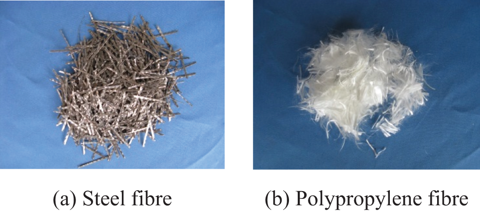
Figure 1: Fibers used in the experiment

12 prism specimens for each mix were cast and then cured in water for 28 days. Subsequently, 9 specimens of OPC, PFC, and SFC withstood 10, 25, and 50 cycles of freeze-thaw activity according to the standard test method. Rapid freeze–thaw cycle test was performed by using the NELD-FC810 concrete rapid freeze–thaw test apparatus. In this test, the temperature at the center of the control specimens ranged from −17°C∼5°C, and each cycle was about 3.5 h. Detailed requirements and operation steps were conducted following the specifications in the GB/T 50082-2009. The dynamic modulus of elasticity of the concrete specimen was obtained by measuring the longitudinal pulse velocity of the specimen (ZBL-U520 non-metal pulse velocity test apparatus) after every 5 cycle’s frost according to the standard test method, which was shown in Fig. 2.
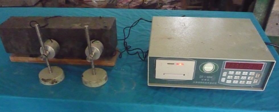
Figure 2: Photograph of concrete dynamic elastic modulus measurement
Then, considering one mold contact surface (100 mm × 400 mm) as the exposure surface, seal the other five surfaces of the specimen with epoxy resin using a brush. After that, harden the epoxy resin through air exposure for 24 h. Then immersed the specimen in NaCl solution with a concentration of 8% for 120 days accelerated test. Took out the specimens from the chloride solution after exposure and drilled three holes in each specimen using a 14 mm diameter rotary impact drill. Sufficient powdered concrete sample was taken out from each hole at a depth of every 5 mm and was mixed to provide the average chloride content in the measured location. Powdered concrete samples with particle size less than 0.63 mm were then selected with a sieve and dried to anhydrous state. After that, 1.5 g samples from each group were dissolved in 10 ml distilled water, vibrated for nearly 1 min, and then stewed for 24 h to completely dissolve the free chloride ion in the sample [26,27]. Mohr titration [28] was finally used to determine the potential of the concentration with chloride ions. According to the calibration test results from the standard chloride concentration and its potential value, the free chloride concentration of every solution containing concrete powder sample can be obtained from the tested potential (Fig. 3).
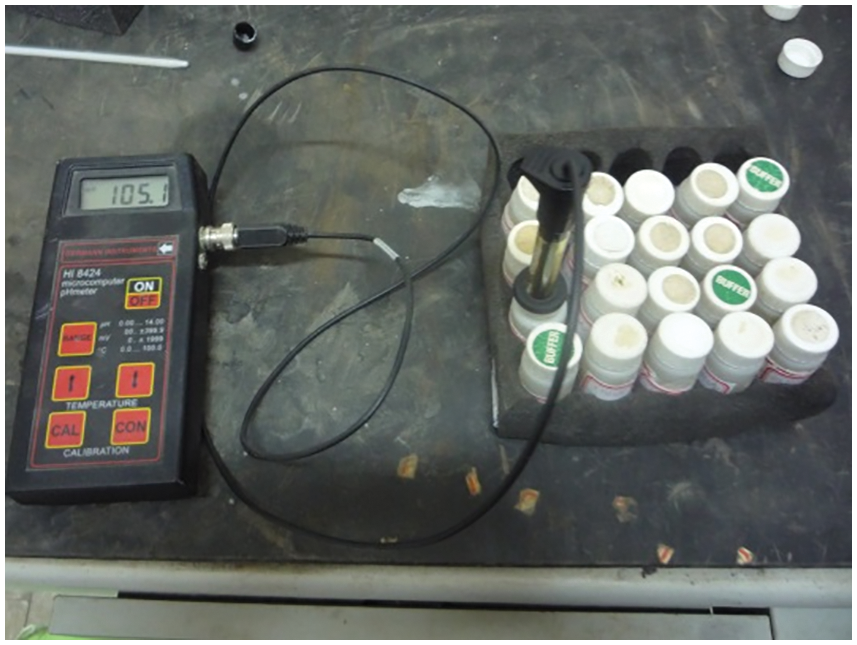
Figure 3: Photograph of chloride ion concentration measurement for concrete powder
The scaling of the concrete surface after 50 freeze-thaw cycles were shown in Fig. 4, which indicated that the damages of OPC and PFC were more serious than those of SFC. The dynamic elastic modulus of each specimen was measured after every 5 cycle’s frost. The results are presented in Fig. 5. The relative dynamic elastic modulus (RDEM) decreased with the increasing of freeze-thaw cycle. However, the descent rate of concrete with steel and polypropylene fibers were smaller than that of ordinary concrete. The reason for this was that the integrity of concrete was improved by the addition of fiber, and the hydrostatic pressure or osmotic pressure could be reduced during the freeze-thaw cycles, then finally reduced the degree of freeze-thaw damage [29,30]. As a result, it can be concluded from the results that the fibers can improve the ability of concrete to resist frost damage from variations of concrete surface and modulus.
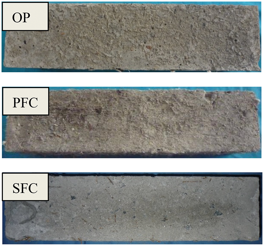
Figure 4: Surface scaling of concrete specimens resulted from 50 freeze-thaw cycles
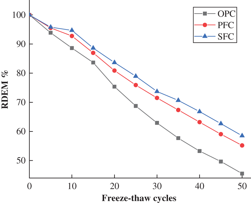
Figure 5: Relative dynamic elastic modulus vs. freeze-thaw cycle
The distribution of free chloride ions in OPC, PFC, SFC specimens after different time freeze-thaw cycles were shown in Figs. 6–8. The concentration of chloride ions in the shallow layer of concrete increases with the increase of freeze-thaw cycles. The change of chloride ion concentration in the deep layer of concrete is a little different between OPC, PFC, and SFC. The concentration of chloride ion in ordinary concrete within depth greater than 27 mm decreases after 10 cycles of freeze-thaw, but increases a little after 25 cycles, and then increases obviously after 50 cycles. After 10 cycles of freeze-thaw, the concentration of chloride ion in concrete mixed with polypropylene fiber within depth greater than 25 mm decreased slightly, while that in steel fiber concrete did not change significantly within depth greater than 32 mm after 10 and 25 cycles of freeze-thaw. This shows that the damage of concrete in the shallow layer within about 30 mm depth is damaged more obviously than that in the deep depth of concrete during freeze-thaw cycles, which results in more chloride ions invading into the concrete, because of the continuous hydration and ice crystal blocking, only when the number of freeze-thaw cycles is more, the internal damage is slightly aggravated, resulting in chloride ion erosion speed up. The free chloride concentration in all of the three types concrete after 50 cycles of freeze-thaw increased more clearly which demonstrated that the damages become more significantly than that after 10 and 25 freeze-thaw cycles.
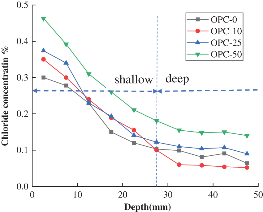
Figure 6: Free chloride ion concentrations of OPC specimens subject to different freeze-thawing cycles
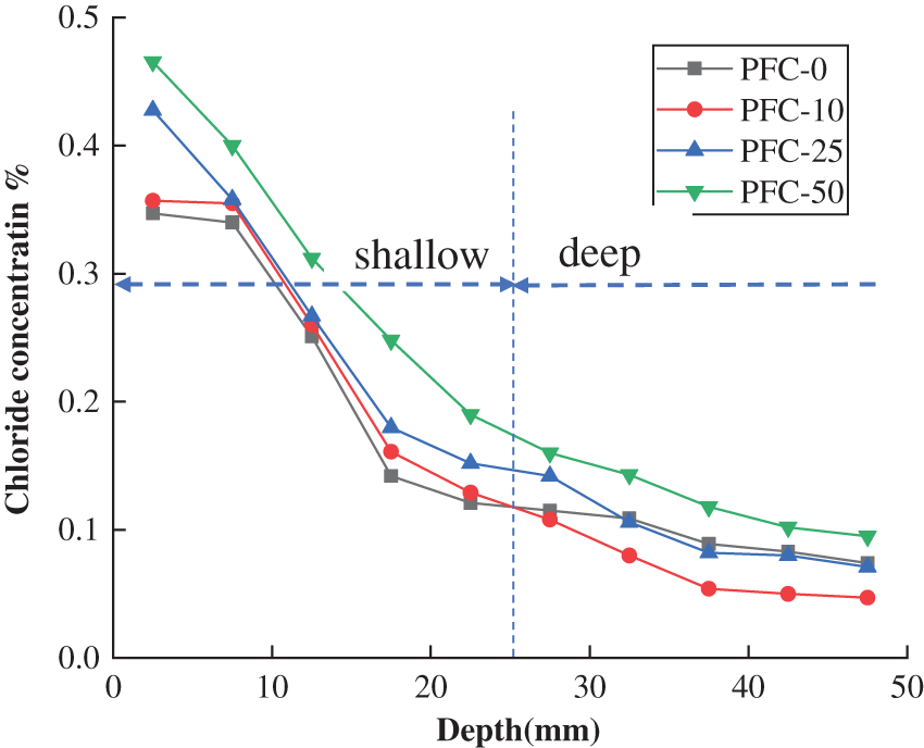
Figure 7: Free chloride ion concentrations of PFC specimens subject to different freeze-thawing cycles
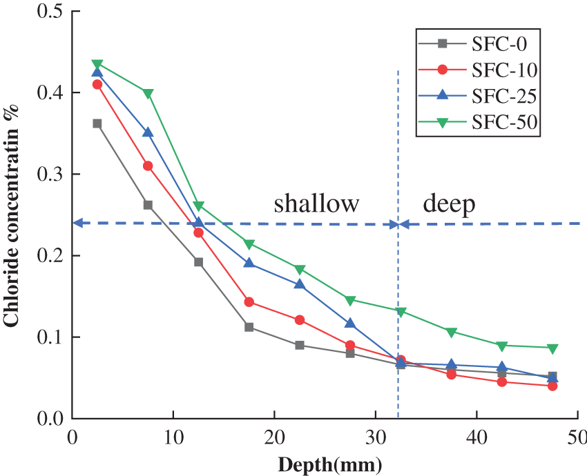
Figure 8: Free chloride ion concentrations of SFC specimens subject to different freeze-thawing cycles
The coefficients λ and v in Eq. (2) can be regressed from Eq. (4) with the dynamic elastic modulus obtained at every 5 freeze-thaw cycle based on the least square method. The regressing results are shown in Table 3. It shows that the time correlation coefficient λ of OPC is larger than those of PFC and SFC, where the law of position correlation coefficient v is inversed. This result indicates that the damage caused by frost attack in OPC is larger than those in PFC and SFC.

The calculated damage of concrete after 50 freeze-thaw cycles is plotted in Fig. 9. The values slightly decrease with the depth. For example, the damage in OPC is 0.54 at the surface and becomes 0.52 at the depth of 50 mm. The values in PFC and SFC are both smaller than those in OPC and decrease with concrete depth.
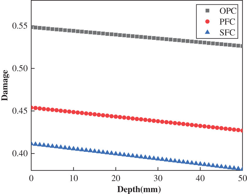
Figure 9: Distribution of damage after 50 freeze-thaw cycles in concretes
As the RDEMs of most concrete prisms started to steadily decline from 10 cycles and reached an allowable value at about 50 cycles, the damages at these two states and a medium value of 25 cycle were representatively selected to analysis.
The damage coefficient calculated by Eq. (7), which is related to concrete depth and freeze-thaw cycles, is shown in Figs. 10–12 for OPC, PFC, and SFC, respectively. The damage coefficients of each type of concrete slightly decrease with the depth but increase significantly with freeze-thaw cycle.
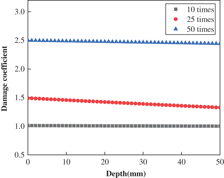
Figure 10: Distribution of damage coefficient in OPC after different times freeze-thaw cycle
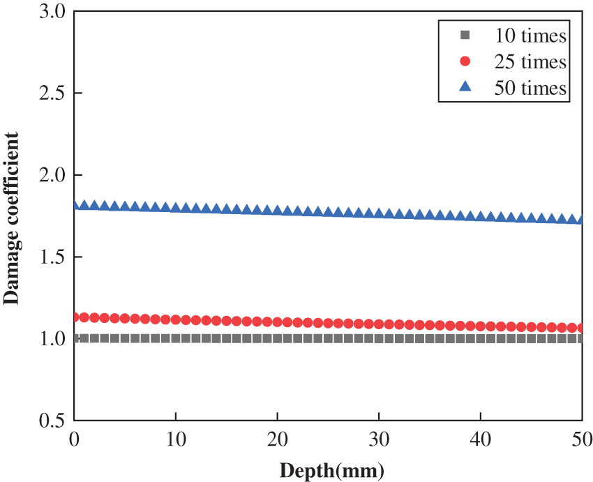
Figure 11: Distribution of damage coefficient in PFC after different times freeze-thaw cycle
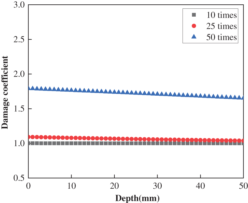
Figure 12: Distribution of damage coefficient in SFC after different times freeze-thaw cycle
For some coastal concrete structures in north area, they always sustain an action of freeze-thaw cycle in sea water, which will make the damage of concrete be more serious than that in fresh water. The damage coefficient will also be greater than that in Figs. 10–12.
4.2 Prediction of Chloride Content
During the experiment, surface chloride concentrations for each type of concrete were obtained after exposed to chloride solution for 120 days (Table 4).

The distribution of chloride ion at different depths of concrete under different exposure time can be obtained from Fick’s second law of diffusion. The apparent diffusion coefficients of sound and damaged concrete were regressed by Eq. (8) [31]:
where C0 is initial chloride concentration, Cs is the surface chloride concentration, Da is the apparent chloride diffusion coefficient, t is the exposure time and erf is the error function.
As the chloride in the surface layer mainly transports by convection instead of diffusion [32,33], the first data at a depth of 0∼5 mm was not considered in the regression [34]. The apparent chloride diffusion coefficients of frost-damaged concrete specimens developed from this equation were shown in Fig. 13, which revealed that the values of chloride diffusion coefficient of these three mixes first decrease before 10 cycles’ freeze-thaw and then increase with freeze-thaw cycles. This attributed to the effect of continuous cement hydration was larger than the frost damage under small amount of cyclic freeze-thaw conditions. As the fibers can alleviate its damage under frost, concrete with steel and polypropylene fibers displays a lower value than the OPC.
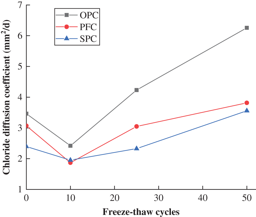
Figure 13: Apparent chloride diffusion coefficients of OPC(O), PFC(P), and SFC(S) specimens subject to different freeze-thaw cycles
The chloride contents in the three types of concrete predicted by Eq. (8) were given in Figs. 14–16 and compared with the corresponding experimental results. It can be obtained that the predicted chloride contents agree well with the experimental data within the depth of 10–30 mm which were shown in the figures as accurate region. In this region, the relative errors between predicted and experimental data were ranged from 0.8% to 14%, and most of them were lower than 10%. However, due to the convection effect, the experimental chloride contents were larger than the predicted chloride contents at the concrete surface within the depth of 0∼10 mm, and most of the relative errors between the predicted and experimental data were in the range of 4%–20%. On the other hand, the test results were inaccurate at deep depths (larger than 30 mm) because of the small values which would be influenced more significantly by the test error, and then made the relative errors be in the range of 20%–50%. It can also be found that most of them are larger than the predicted values.
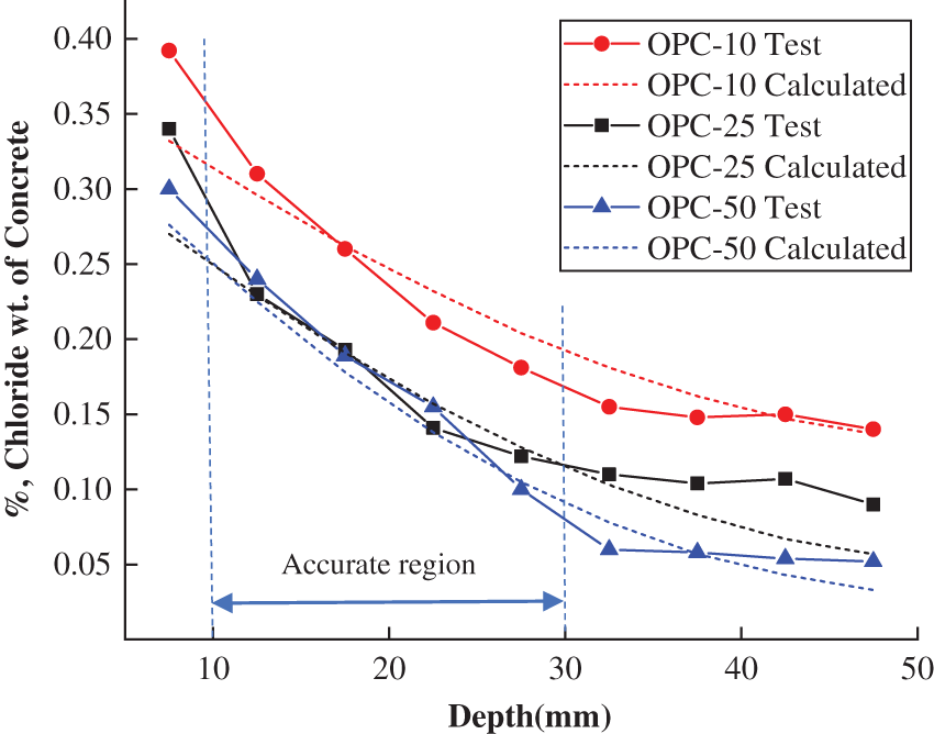
Figure 14: Distribution of chloride concentration after 10, 25, and 50 freeze-thaw cycles in OPC (%)
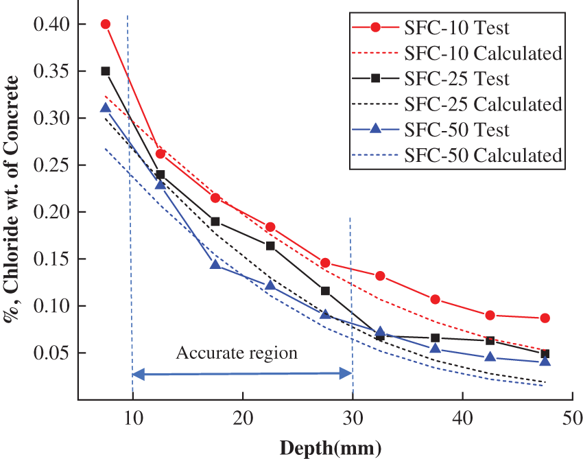
Figure 15: Distribution of chloride concentration after 10, 25, and 50 freeze-thaw cycles in PFC (%)
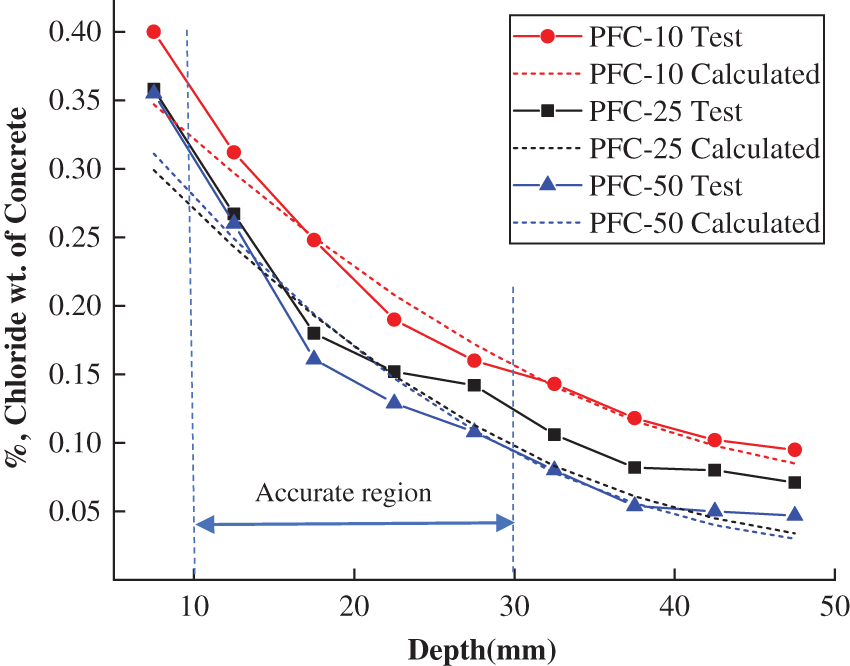
Figure 16: Distribution of chloride concentration after 10, 25, and 50 freeze-thaw cycles in SFC (%)
Based on the experimental results and the analysis model of the damage distribution induced by freeze-thaw cycle, the following conclusions can be drawn:
(1) Concrete exhibited non-uniform damage under freeze-thaw cycles. The surface spalling of OPC and PFC were more serious than those of SFC after 50 freeze-thaw cycles which indicated that the damage degree at the concrete surface is larger than that at a deep depth. The relative dynamic elastic modulus (RDEM) decreased with the increasing of freeze-thaw cycle numbers. The decline speed of RDEM for different types of concrete was in an order as OPC > PFC > SFC, which indicated that PPF and SF can both improve the ability of concrete to resist frost damage.
(2) For the concrete after 10 and 25 freeze-thaw cycles, the chloride ion concentration in the shallow layer (within about 30 mm depth) increased with the increasing of freeze-thaw cycle numbers. This phenomenon indicated that the frost damage of concrete in the shallow layer within about 30 mm depth is more obviously than that in the deeper depth after few times of freeze-thaw cycle. The free chloride concentration at any position of OPC, PSC and SFC increased more obviously after 50 cycles of freeze-thaw which demonstrated that the damages become more significantly than those after 10 and 25 freeze-thaw cycles.
(3) A model considering the freeze-thaw cycle and concrete depth was proposed in this study to express the non-uniform damage of concrete under freeze-thaw cycles. According to this model, the calculated damage values in PFC and SFC were both smaller than those in OPC and decreased with concrete depth. Non-uniform distributed chloride diffusion coefficient was found to increase with the increasing of the freeze-thaw cycle numbers and decrease slightly with the concrete depth. Based on this model, the chloride concentrations in frost damaged concrete were predicted and obtained to agreed well with the test result within the depth of 10 to 30 mm. The relative errors of most data in this region were lower than 10%.
Funding Statement: The work described in this paper was supported by the Graduate Research Innovation Program of Jiangsu University (Si Y. D., SJCX21_1689), and the Foundation from the National Natural Science Foundation of China (Yan Y. D., 51608233).
Conflicts of Interest: The authors declare that they have no conflicts of interest to report regarding the present study.
References
1. Xu, Y. Q., Ye, H. S., Yuan, Q., Shi, C. J., Gao, Y. et al. (2022). The durability of concrete subject to mechanical load coupled with freeze–thaw cycles: A review. Archives of Civil & Mechanical Engineering, 22(1), 1–18. https://doi.org/10.1007/s43452-021-00370-9 [Google Scholar] [CrossRef]
2. Langaroudi, M. A. M., Mohammadi, Y. (2019). Effect of nano-clay on the freeze–thaw resistance of self-compacting concrete containing mineral admixtures. European Journal of Environmental and Civil Engineering, 26(2), 481–500. [Google Scholar]
3. Pakkala, T. A., Köliö, A., Lahdensivu, J., Kiviste, M. (2014). Durability demands related to frost attack for Finnish concrete buildings in changing climate. Building and Environment, 82, 27–41. https://doi.org/10.1016/j.buildenv.2014.07.028 [Google Scholar] [CrossRef]
4. Si, Z., Du, X., Huang, L., Li, Y. (2020). Meso-scale failure of freezing–thawing damage of concrete under uniaxial compression. Applied Sciences, 10(4), 1252. https://doi.org/10.3390/app10041252 [Google Scholar] [CrossRef]
5. Lv, X. J., Yu, L., Chai, M. M. (2021). Mechanical properties and micro structure of cement concrete in freeze-thaw environment. E3S Web of Conferences, vol. 233, 01011. Strasbourg, France. EDP Sciences. [Google Scholar]
6. Rao, M., Li, M., Yang, H., Li, X., Dong, Y. (2016). Effects of carbonation and freeze-thaw cycles on microstructure of concrete. Journal of Wuhan University of Technology-Mater. Sci. Ed., 31(5), 1018–1025. https://doi.org/10.1007/s11595-016-1484-7 [Google Scholar] [CrossRef]
7. Pogorelov, S. N., Semenyak, G. S. (2016). Frost resistance of the steel fiber reinforced concrete containing active mineral additives. Procedia Engineering, 150, 1491–1495. https://doi.org/10.1016/j.proeng.2016.07.088 [Google Scholar] [CrossRef]
8. Wen, Y., Sun, H., Hu, S. D., Xu, G. M., Wu, X. Z. et al. (2021). Microstructure and life prediction model of steel slag concrete under freezing-thawing environment. Nanotechnology Reviews, 10(1), 1776–1788. https://doi.org/10.1515/ntrev-2021-0109 [Google Scholar] [CrossRef]
9. Luo, T., Zhang, C., Sun, C., Zheng, X., Ji, Y. et al. (2020). Experimental investigation on the freeze–thaw resistance of steel fibers reinforced rubber concrete. Materials, 13(5), 1260. https://doi.org/10.3390/ma13051260 [Google Scholar] [PubMed] [CrossRef]
10. Liu, L., Guan, Q., Zhang, L., Liu, C., Chen, X. et al. (2022). Evaluation of the compressive-strength reducing behavior of concrete containing rubber aggregate. Cleaner Materials, 4, 100057. https://doi.org/10.1016/j.clema.2022.100057 [Google Scholar] [CrossRef]
11. Chen, D., Deng, Y., Shen, J., Sun, G., Shi, J. (2021). Study on damage rules on concrete under corrosion of freeze-thaw and saline solution. Construction and Building Materials, 304, 124617. https://doi.org/10.1016/j.conbuildmat.2021.124617 [Google Scholar] [CrossRef]
12. Liu, M., Liu, D., Qiao, P., Sun, L. (2021). Characterization of microstructural damage evolution of freeze-thawed shotcrete by an integrative micro-CT and nanoindentation statistical approach. Cement and Concrete Composites, 117, 103909. https://doi.org/10.1016/j.cemconcomp.2020.103909 [Google Scholar] [CrossRef]
13. Peng, R. X., Qiu, W. L., Teng, F. (2020). Three-dimensional meso-numerical simulation of heterogeneous concrete under freeze-thaw. Construction and Building Materials, 250, 118573. https://doi.org/10.1016/j.conbuildmat.2020.118573 [Google Scholar] [CrossRef]
14. González, D. C., Mena, Á., Mínguez, J., Vicente, M. A. (2021). Influence of air-entraining agent and freeze-thaw action on pore structure in high-strength concrete by using CT-scan technology. Cold Regions Science and Technology, 192, 103397. https://doi.org/10.1016/j.coldregions.2021.103397 [Google Scholar] [CrossRef]
15. Qu, F., Niu, D. T. (2013). Chloride ion diffusion behavior of concrete after freezing and thawing cycles. In: Advanced materials research, vol. 671, pp. 1652–1656. Trans Tech Publications Ltd., Stafa-Zurich, Switzerland. [Google Scholar]
16. Kuosa, H., Ferreira, R. M., Holt, E., Leivo, M., Vesikari, E. (2014). Effect of coupled deterioration by freeze-thaw, carbonation and chlorides on concrete service life. Cement and Concrete Composites, 47, 32–40. https://doi.org/10.1016/j.cemconcomp.2013.10.008 [Google Scholar] [CrossRef]
17. Jacobsen, S., Gran, H. C., Sellevold, E. J., Bakke, J. A. (1995). High strength concrete—freeze/thaw testing and cracking. Cement and Concrete Research, 25(8), 1775–1780. https://doi.org/10.1016/0008-8846(95)00173-5 [Google Scholar] [CrossRef]
18. Wieczorek, A., Koniorczyk, M., Bednarska, D., Grabowska, K. (2018). The transport properties of cement mortars subjected to freeze-thaw cycles. E3S Web of Conferences, vol. 49, 00128. Polańczyk, Poland. EDP Sciences. [Google Scholar]
19. Wittmann, F. H., Zhang, P., Zhao, T. (2006). Influence of combined environmental loads on durability of reinforced concrete structures. Restoration of Buildings and Monuments, 12(4), 349–362. https://doi.org/10.1515/rbm-2006-6069 [Google Scholar] [CrossRef]
20. Wang, Y., An, M., Yu, Z., Han, B., Ji, W. (2018). Experimental and cellular-automata-based analysis of chloride ion diffusion in reactive powder concrete subjected to freeze–thaw cycling. Construction and Building Materials, 172, 760–769. https://doi.org/10.1016/j.conbuildmat.2018.03.271 [Google Scholar] [CrossRef]
21. Du, P., Yao, Y., Wang, L., Xu, D. Y., Zhou, Z. H. et al. (2016). Deformation of a concrete matrix subject to a cyclic freeze–thaw process. RSC Advances, 6(63), 58417–58425. https://doi.org/10.1039/C6RA01472K [Google Scholar] [CrossRef]
22. Xu, P., Wu, Y. M., Wang, Z. J., Huang, L. (2020). Distribution laws of freeze-thaw cycles and unsaturated concrete experiments in cold-region tunnels. Cold Regions Science and Technology, 172, 102985. https://doi.org/10.1016/j.coldregions.2019.102985 [Google Scholar] [CrossRef]
23. Gerard, B., Pijaudier-Cabot, G., Laborderie, C. (1998). Coupled diffusion-damage modelling and the implications on failure due to strain localization. International Journal of Solids and Structures, 35(31–32), 4107–4120. https://doi.org/10.1016/S0020-7683(97)00304-1 [Google Scholar] [CrossRef]
24. GB 175-2007 (2007). Common portland cement. Standards Press of China, Beijing. [Google Scholar]
25. GB/T 50082-2009 (2009). Standard for test methods of long-term performance and durability of ordinary concrete. China Architecture and Building Press, Beijing. [Google Scholar]
26. Nordtest Nt Build 443 (1995). Accelerated chloride penetration. Finland: Nordtest. [Google Scholar]
27. Chang, H., Mu, S. (2017). Detecting the water-soluble chloride distribution of cement paste in a high-precision way. Journal of Visualized Experiments, 129, e56268. https://doi.org/10.3791/56268 [Google Scholar] [PubMed] [CrossRef]
28. Li, P. Z., Xie, H. C. (2000). RCT-rapid chloride ion detection method and its application. Concrete, 2000(12), 46–48. [Google Scholar]
29. Al-Lebban, M. F., Khazaly, A. I., Shabbar, R., Jabal, Q. A., Al Asadi, L. A. R. (2021). Effect of polypropylene fibers on some mechanical properties of concrete and durability against freezing and thawing cycles. In: Key engineering materials, vol. 895, pp. 130–138. Trans Tech Publications Ltd., Stafa-Zurich, Switzerland. [Google Scholar]
30. Zhang, Q., Xu, W., Sun, Y., Ji, Y. (2022). Investigation on mechanical and microstructure properties of steel fiber reinforced concrete. Advances in Materials Science and Engineering, 2022, 1–18. https://doi.org/10.1155/2022/3681132 [Google Scholar] [CrossRef]
31. Li, W., Guo, L. (2021). Peridynamic investigation of chloride diffusion in concrete under typical environmental factors. Ocean Engineering, 239, 109770. https://doi.org/10.1016/j.oceaneng.2021.109770 [Google Scholar] [CrossRef]
32. DuraCrete (2000). General guidelines for durability design and redesign. Demark: The European Union, Bruxelles. [Google Scholar]
33. Qiu, J., Guo, P., Xing, M., Guan, X., Xiong, G. (2020). Study on capillary water absorption properties of polypropylene fibre coal gangue ceramist concrete under freeze-thaw damage. The Journal of Engineering, 2020(3), 98–103. https://doi.org/10.1049/joe.2019.0773 [Google Scholar] [CrossRef]
34. Neville, A. (1995). Chloride attack of reinforced concrete: An overview. Materials and Structures, 28(2), 63–70. https://doi.org/10.1007/BF02473172 [Google Scholar] [CrossRef]
Cite This Article
 Copyright © 2023 The Author(s). Published by Tech Science Press.
This work is licensed under a Creative Commons Attribution 4.0 International License , which permits unrestricted use, distribution, and reproduction in any medium, provided the original work is properly cited.


 Submit a Paper
 Propose a Special lssue
 View Full Text
 Download PDF
 Downloads
 Citation Tools