
 Submit a Paper
 Propose a Special lssue
 Open Access
ARTICLE

Investigating the Retrofit of RC Frames Using TADAS Yielding Dampers
1 Department of Civil Engineering, Kermanshah Branch, Islamic Azad University, Kermanshah, 6718997551, Iran
2 Department of Civil Engineering, Razi University, Kermanshah, 6714414971, Iran
* Corresponding Author: Mehrzad TahamouliRoudsari. Email:
Structural Durability & Health Monitoring 2022, 16(4), 343-359. https://doi.org/10.32604/sdhm.2022.07927
Received 11 July 2019; Accepted 23 April 2021; Issue published 03 January 2023
 View Full Text
 Download PDF
Abstract
TADAS dampers are a type of passive structural control system used in the seismic design or retrofitting of structures. These types of dampers are designed so that they would yield before the main components of the structure during earthquake. This dissipates a large portion of the earthquake’s energy and reduces the energy dissipation demand in the main components of the structure. Considering its suitable performance, this damper has been the subject of numerous studies. However, there are still ambiguities regarding the effect of the number of these dampers on the retrofitting of reinforced concrete (RC) frames and their design procedure. In this study, a single-story, single-bay RC frame with the scale of 1:3, equipped with the TADAS damper, was subjected to hysteresis loading until the drift of 4%. Then, for further assessment, 48 calibrated numerical models were constructed in ABAQUS and the effects of the number of TADAS dampers and column axial force upon the stiffness, strength, and ductility of the frame were accurately investigated. Also, a number of formulations were presented to calculate how the stiffness and lateral strength of the retrofitted frame are affected by an increase in the number of the TADAS plates. The results showed that if the shear capacity of the retrofitted frame is three times that of the initial frame, the structure would have the best response. In addition, if the axial force in the columns exceeds 0.2 Pcr the energy dissipation and ductility factor of the frame drastically decrease.Keywords
The Triangular-Plate Added Damping and Stiffness (TADAS) is amongst the seismic systems whose addition to a structure not only improves its seismic parameters, but also increases its stiffness and strength to some extent. With its premature yielding, this type of damper absorbs a portion of the energy entering the structure, which results in minimum damage being inflicted upon the main components of the structure. Due to the suitable performance of this type of damper, the numerous investigations are conducted on this issue, some of these are presented in the following.
Yielding plates were first used in the structure of nuclear power plants [1]. Then, further studies were carried out in Berkley University on X-shaped yielding plates used in a three-story structure [2,3].
In 2011, Yousefzadeh et al. [4] studied the optimal placement and specifications of the spell TADAS plates. The study was focused on a number of steel structures that did not perform desirably against earthquakes. The results showed that optimizing the placement of the damper is influential in improving the behavior of the structure. Mahmoudi et al. [5] studied the strength reduction factor of special RC frames retrofitted with TADAS plates. In that study, the OpenSees computer program was used to perform nonlinear incremental dynamic analyses. The results showed that the strength reduction factor of frames with TADAS plates were higher than the frames that did not incorporate them. The seismic behavior of RC frames with TADAS plates are investigated by Moghaddasi et al. [6]. The analytical models included three eight-story RC frames whose lateral bracing systems were Chevron braces with TADAS dampers. The results of the dynamic analyses revealed that in addition to improving the seismic behavior of the frame, the TADAS damper also significantly improves the energy dissipation of the RC frames.
In 2016, Saeedi et al. [7] investigated and compared the effects of TADAS dampers on steel structures. In addition to presenting a series of relationships to calculate the stiffnesses of the plates, the authors showed that this type of damper clearly increases stiffness and decreases the drifts of the stories. Shojaeifar et al. [8] investigated the behavior of the TADAS plate in combined with another yielding damper. They examine this type of damper in the beam-column connection region. The result of this study shows that this type of damper can absorb large amount of earthquake input energy of the structure.
Numerous investigations have also been carried out on Added Damping and Stiffness (ADAS) dampers [9–11]. One of the fields of yielding dampers is the comparison between the geometries of yielding plates used in structures. Alehashem et al. [12] presented a comparison between the TADAS and ADAS yielding plates. The results were indicative of an increase in the period of structures equipped with these two types of dampers, with the structures incorporating the ADAS plates having the larger period. ADAS and TADAS are not the only yielding dampers and other concepts have been utilized in structures by other researchers [13–15].
Many kinds of research in regards to the retrofitting of RC structures with steel elements have been done [16–22]. In these investigations, the effect of adding new elements such as the steel shear wall and different kinds of braces on the stiffness and ultimate strength of the frame were evaluated. New experimental studies on retrofitting RC structure with various kinds of braces such as EBF, X, Knee and Chevron with the shear link were done by TahamouliRoudsari et al. [23]. The studies have revealed that although the concentric brace enhances the both ultimate strength and stiffness of the concrete frame, it decreases its ductility. Also, regarding the performance of eccentric braces, it was observed that they exhibit appropriate behavior, but they lead to significant damage to the frame.
New investigations showed that retrofitting RC structures using TADAS and ADAS dampers results in a far more desirable performance for the structure than other systems such as braces of different types [24]. In that study, although it was proved that the TADAS and ADAS dampers are superior to other systems, no accurate approach was presented for the design and retrofit of RC frames using yielding dampers.
The aim of the present study is to demonstrate the seismic behavior of concrete moment-resisting frame affected by number of TADAS plates and column axial force. The experimental investigations of TahamouliRoudsari et al. [24] were used to verify the numerical model. Then, 48 pushover analyses were conducted to describe the effect of the number of yielding plates on the seismic parameters of the frames such as ductility, energy dissipation, and effective stiffness. Finally, some relationships were proposed for the calculation of stiffness and lateral strength of the structure for increasing numbers of yielding plates. The results demonstrate that when the ultimate lateral strength of the equipped frame is three times greater than that of the initial frame, the seismic parameters of the structure are in an optimal state. Also, if the axial force of the column exceeds 0.2 Pcr, both the energy dissipation and ductility of the structure are significantly decreased.
The experimental model constructed by TahamouliRoudsari et al. [24] was used for the verification of the numerical model. The scale of the frame was 1:3, with the lengths of the beam and the column being 145 and 100 cm, respectively (Fig. 1). Also, the dimensions of the beam and the columns were 15 cm × 15 cm and the dimensions of the foundation were 20 cm × 30 cm. The experimental model was modeled in ABAQUS using the following assumptions:
• In the experimental study, all of the failures took place in the plates and no failure was seen in neither the weldings nor the bolts. Therefore, in ABAQUS, the “Merge” command was used instead of modeling the welding.
• Since failure was not observed in different parts of the brace, the connections between these parts were furnished with “Tie” constrained in ABAQUS.
• The materials of the concrete and the steel were considered to be isotropic.
• The slippages between the concrete and the steel rebars and also between the steel plates connected to the beam were overlocked.
• The “Tie” command was used to account for the steel plates in contact with the RC frame.
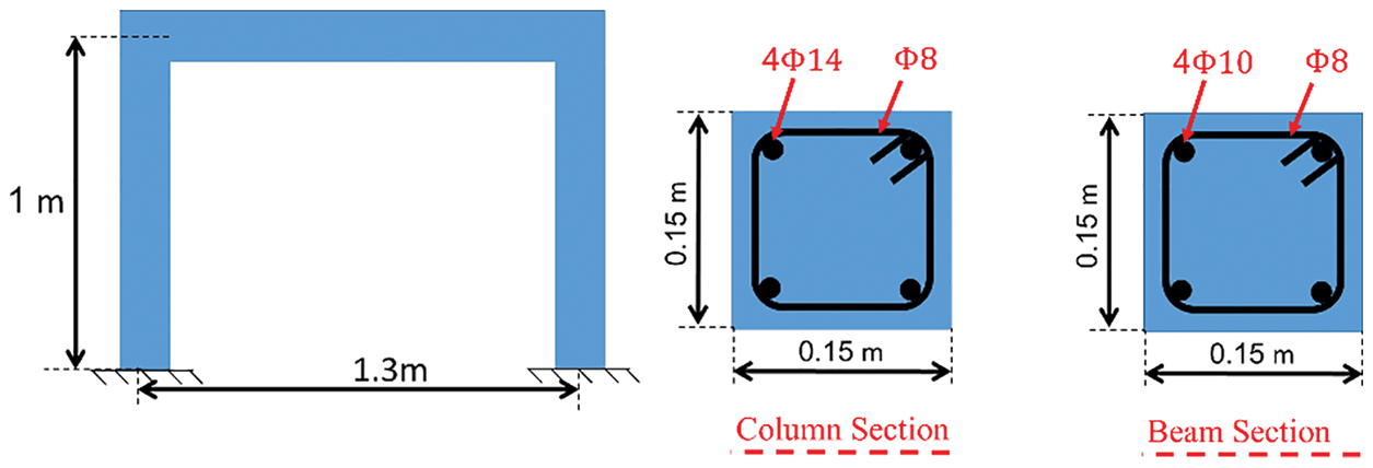
Figure 1: Schematic of the experimental RC frame and reinforcement details [11]
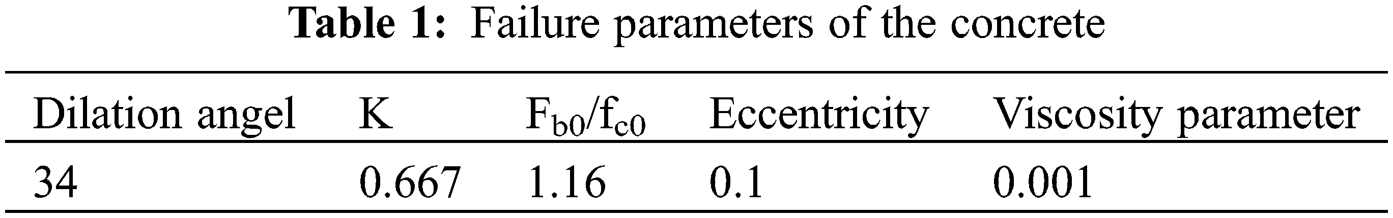
Fig. 1 shows the schematic of the experimental RC frame and reinforcement details [11]. To model the components of the frame such as the concrete and steel plates, the eight–node solid element was used and the steel rebars were modeled using beam elements. To model the concrete damage behavior, the Concrete Damage Plasticity (CDP) option was used, which is capable of simulating the failure behavior of concrete and its behavior under complex loadings Jankowiak et al. [25]. Table 1 contains the parameters of the CDP option in ABAQUS. In this table, K and Fb0/fc0 are the second stress-invariant-ratio on the tensile meridian, the initial equibiaxial compressive ratio of yield stress to initial uniaxial-compressive of yield stress, respectively.
One of the most important parts of a finite element analysis is the selection of a suitable mesh grid. To select suitable mesh dimensions, a sensitivity analysis was performed on the mesh of different parts of the frame. A finer mesh was employed in the parts with larger deformations and stresses. Table 2 presents the mesh dimensions of different parts of the model. The finite element model and its mesh grid are shown in Figs 2a and 2b. The pushover displacement-control quasi-static load was applied to the frame in the lab until the drift of 4.2%. Comparing the experimental push results and FEM model the in Fig. 3 shows the high accuracy of the FEM model and that it can be used for further analyses.
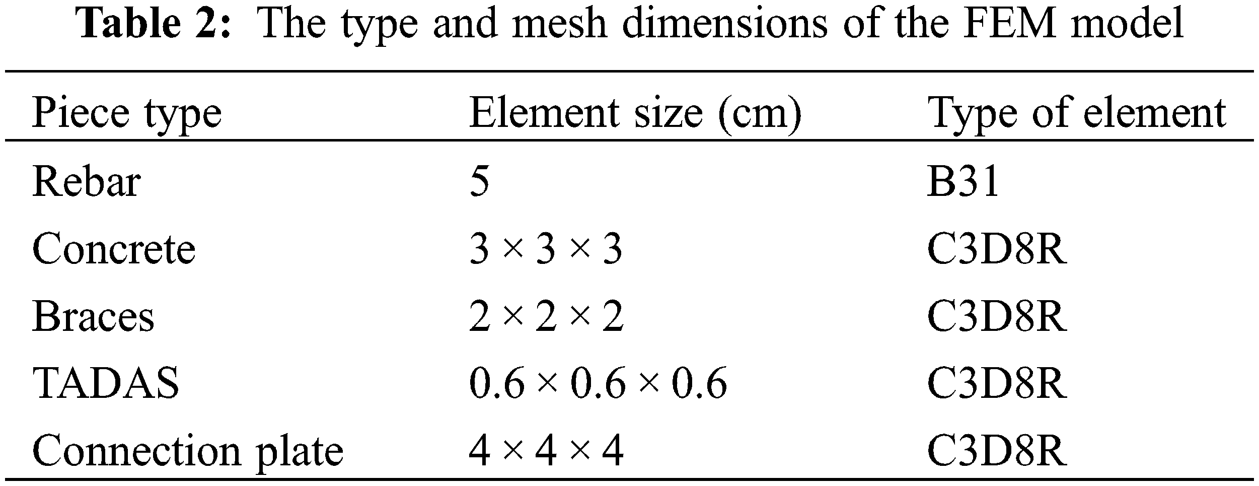
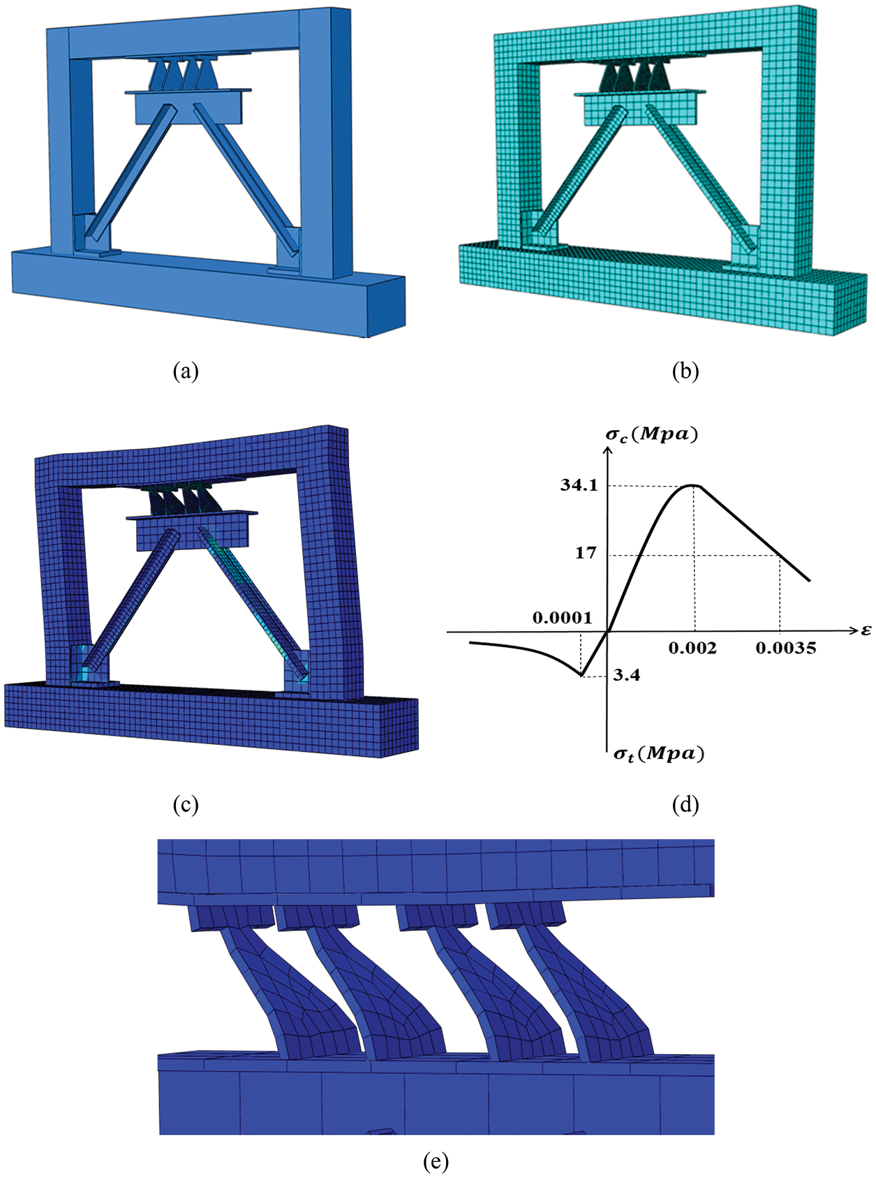
Figure 2: The FEM (a) The RC frame (b) The mesh (c) The frame at the end of loading (d) Relationship between stress and strain of the concrete (e) The TADAS damper after loading
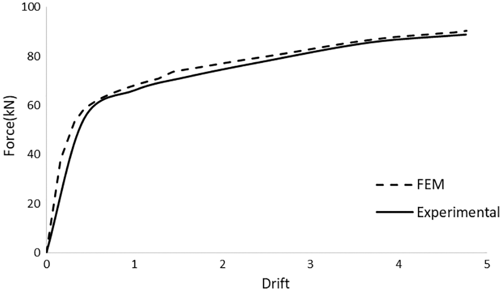
Figure 3: Comparison between the force–drift diagram obtained from ABAQUS and the experimental push results
The stress-strain diagram used in this study (Fig. 2d) depicts the concrete behavior that was introduced by Kent et al. [26] in the form of Eq. (1). In this formula,
3 Numerical Models and the Calculation of Their Seismic Properties
If properly designed, the addition of TADAS dampers to the frame improves its seismic behavior. In this regard, the following can be mentioned:
• Adding this damper to the RC frame considerably decreases the pinching effect.
• If a high number of yielding plates are used, due to the increasing in the shear capacity, the plates yield later than the frame itself. In other words, prior to the yielding of then plates, substantial failure would take place in the frame. Conversely, if a low number of yielding plates are used, due to their low shear capacity, the lateral capacity of the frame would be low and therefore, the retrofitting scheme would be ineffective. So, the number of the TADAS plates has to be determined so that the lateral capacity of the frame would be increased, while as the same time the TADAS plates would yield before the lateral yielding of the frame.
• The dampers have to be placed in a portion of the structure which, during earthquake or the application of an external force, carries the maximum drift.
• With a suitable design, failure can be directed to take place in the dampers which can be replaced after earthquake.
• The vertical load in the columns can be directly influence the seismic parameters of the frame. These effects were not taken into account in the TahamouliRoudsari et al. [24] study.
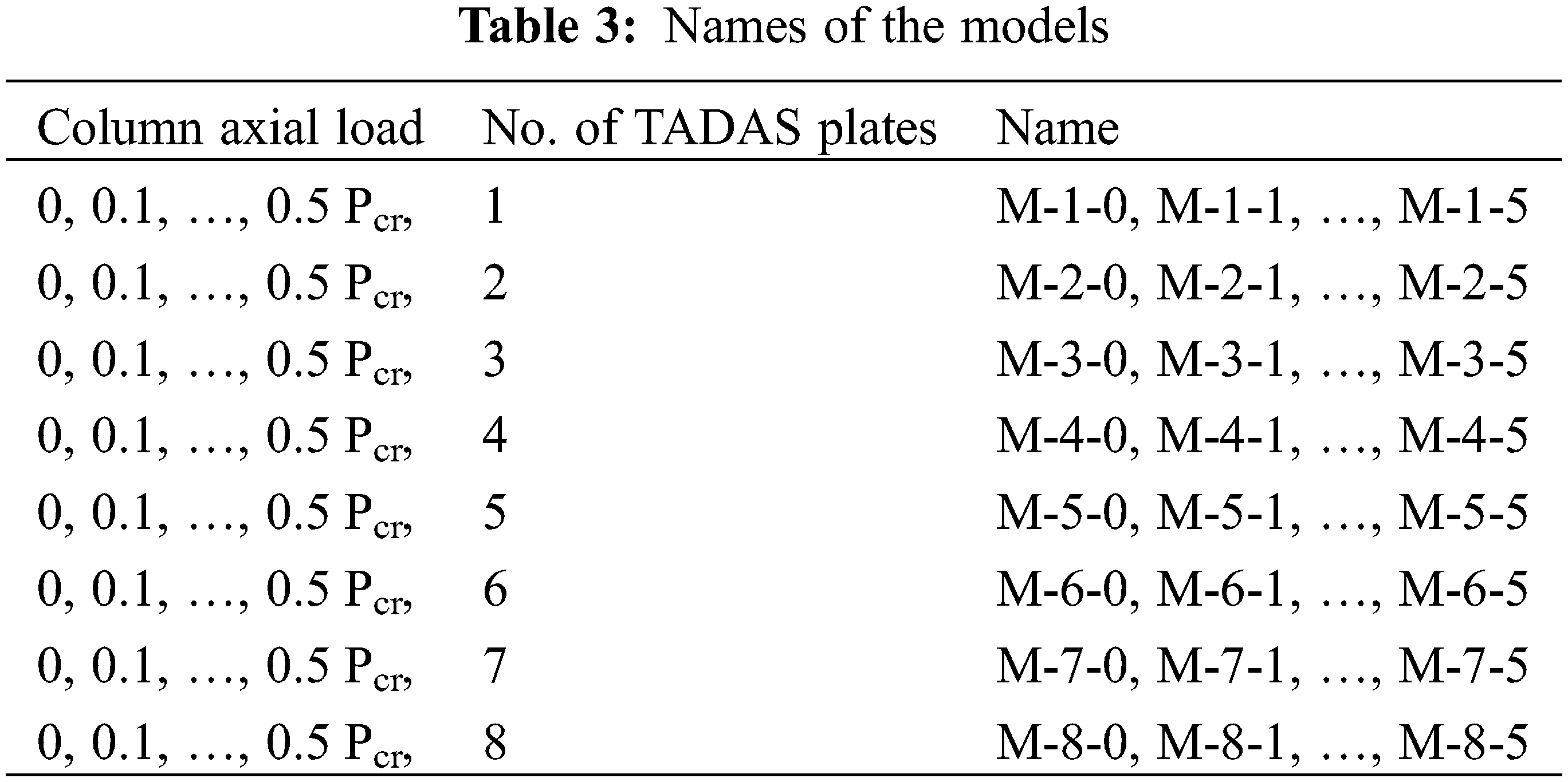
Thus, one of the important points in the behavior of structures retrofitted with this type of damper that needs to be addressed is the sensitivity of the seismic parameter of the frame to the number of the TADAS plates and the axial force of columns. In this study, based on 48 verified FEM models, the effects of the number of TADAS yielding dampers and column axial load on the seismic parameters of the frame have been investigated. Also, theoretical relationships have been presented for a quick estimation of the stiffness and strength of the frame. The RC frame used in the TahamouliRoudsari et al. [24] study, with the same dimensions, was used for the numerical analyses but the number of TADAS dampers varied from 1 to 8. Also, six cases of column axial force were considered (0, 0.1, 0.2, …, 0.5 Pcr) in the analyses. Pcr is the critical load of the columns which, based on the ACI 318-14 [28], was calculated to be 405 KN. For a more convenient interpretation of the results, the models were given separate names, as shown in Table 3. For instance, M3-5 is a model with 3 TADAS yielding plates and a column axial force of 0.5 Pcr.
The backbone diagram can be obtained from the max-points in the hysteresis diagram. Afterwards, using the FEMA [29] guideline, the backbone diagram can be approximated by an idealized bilinear diagram. The equivalent bilinear diagram has to be drawn so that the area beneath it would be equal to that of the backbone diagram. The backbone and equivalent bilinear diagrams are qualitatively shown in Fig. 4. The parameters Vw, Vy, and Vd are the design strength, yield strength, and ultimate strength, respectively. The parameters of stiffness and ductility are defined by Eqs. (2) and (3).
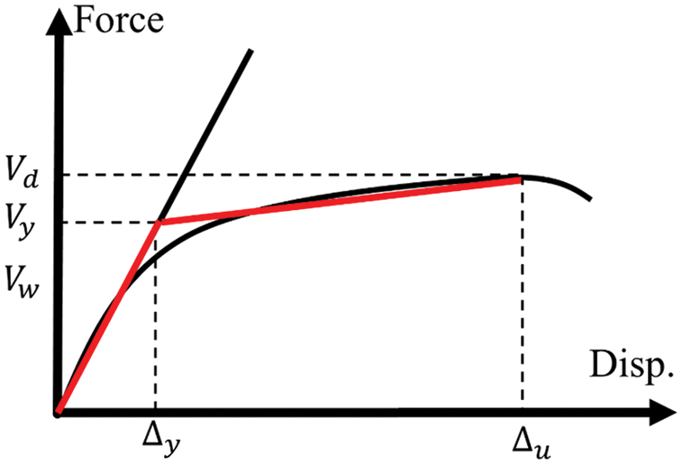
Figure 4: Bilinear representation of the pushover curve [23]
4 Numerical Models and Assessing the Results
In the pushover analyses, the lateral displacement lasted until a decrease was seen in the curve. Then, bilinearizing the diagram, the effects of the axial force of columns and the number of TADAS yielding dampers on the seismic behavior of the RC frame including lateral stiffness, dissipated energy, and ductility factor were evaluated. Also, to quickly estimate the strength and the stiffness of the plates, relationships were presented that can, with suitable accuracy, calculate the ultimate strength and the stiffness of the RC frame with respect to an increase in the number of the plates. Fig. 5 illustrates the equivalent bilinear and force–displacement curve of four of the FEM models. In these plots, the vertical and horizontal axes respectively represent lateral force in kN and drift.
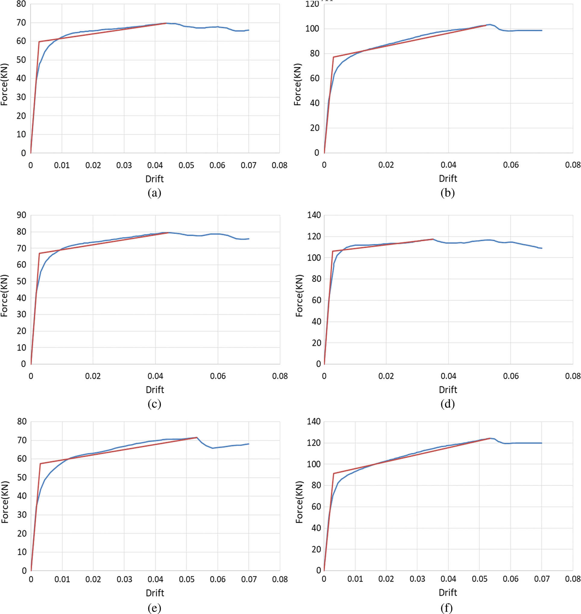
Figure 5: The force-displacement and bilinear diagrams of the (a) M-2-1 (b) M-5-0 (c) M-3-1 (d) M-8-3 (e) M-2-0 (f) M-7-0 models
Fig. 6 displays the variation of the effective stiffness of the RC frame as a result of change in the number of TADAS dampers and column axial load. As it can be observed, by variation of the number of yielding plates, the stiffness of the RC frame increases. The increasing rate of the stiffness with respect to the increase in the number of dampers is almost the same in all of the samples and is equal to 3.31 kN/mm per TADAS plate.
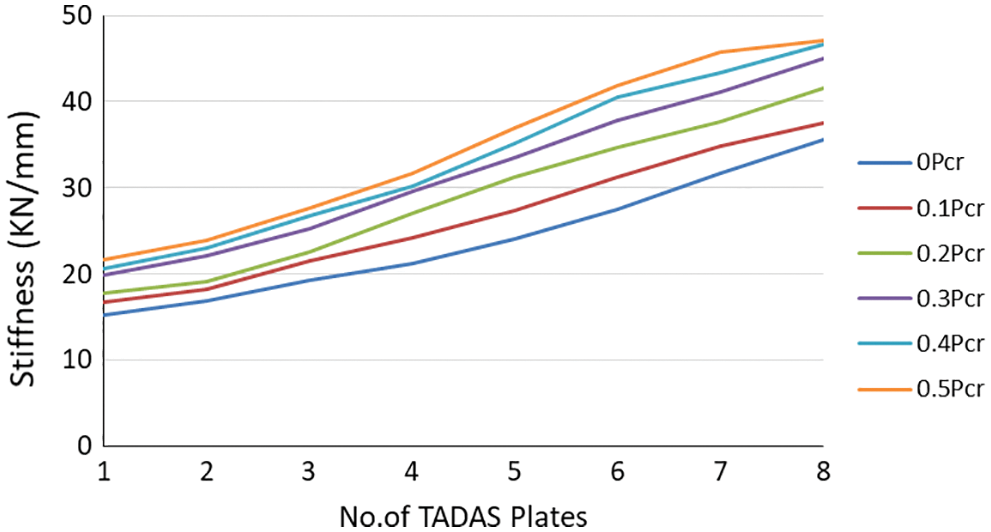
Figure 6: The stiffness of the frame with respect to variation of TADAS yielding plates and column force increase
In the experimental model [24], the yield stress and young’s modulus of the TADAS plates were 198 Gpa and 221 MPa, respectively. To calculate its stiffness, the support conditions of the TADAS plate were considered to be fixed on one end and guided on the other (Fig. 7) and the lateral stiffness was calculated using Castigliano’s method. Based on Castigliano’s second theorem, the displacement of a point on the beam is calculated via the following equation:
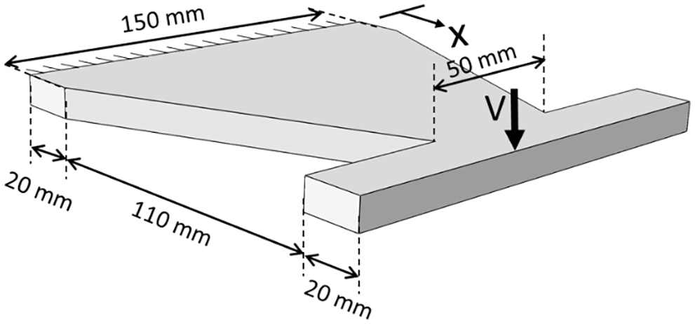
Figure 7: Dimensions of the TADAS plate and its support conditions
In this equation, EI and M are the flexural rigidity and bending moment of the plate, respectively.
The lateral stiffness of one TADAS plate was calculated to be 3.46 kN/mm which is reasonably accurate when compared to the average value calculated by ABAQUS, i.e., 3.31 kN/mm. Therefore, instead of carrying out time-consuming numerical analyses, this formula can be used to calculate the increase in the stiffness of the structure with respect to the increase in the number of TADAS plates.
Eq. (5) has been obtained based on the modeling of the TADAS plate with beam elements. Since the length of the element is smaller than its width, beam elements introduce a degree of inaccuracy into the modeling. To evaluate the level of accuracy of Eqs. (4)–(6), the TADAS plate was also modeled in ABAQUS (Fig. 8). The specifications of the steel were taken from reference [24]. The bottom of the plate was clamped and the top of the plate had a guided support. Fig. 8a shows the pushover diagram of the TADAS plate. The initial stiffness obtained for the diagram was a 3.31 kN/mm, which confirms to the experimental data. The discrepancy in the calculated stiffnesses by the beam element model and the shell model is less than 5%. Therefore, Eq. (5) and the beam element model are reliable for engineering calculations.
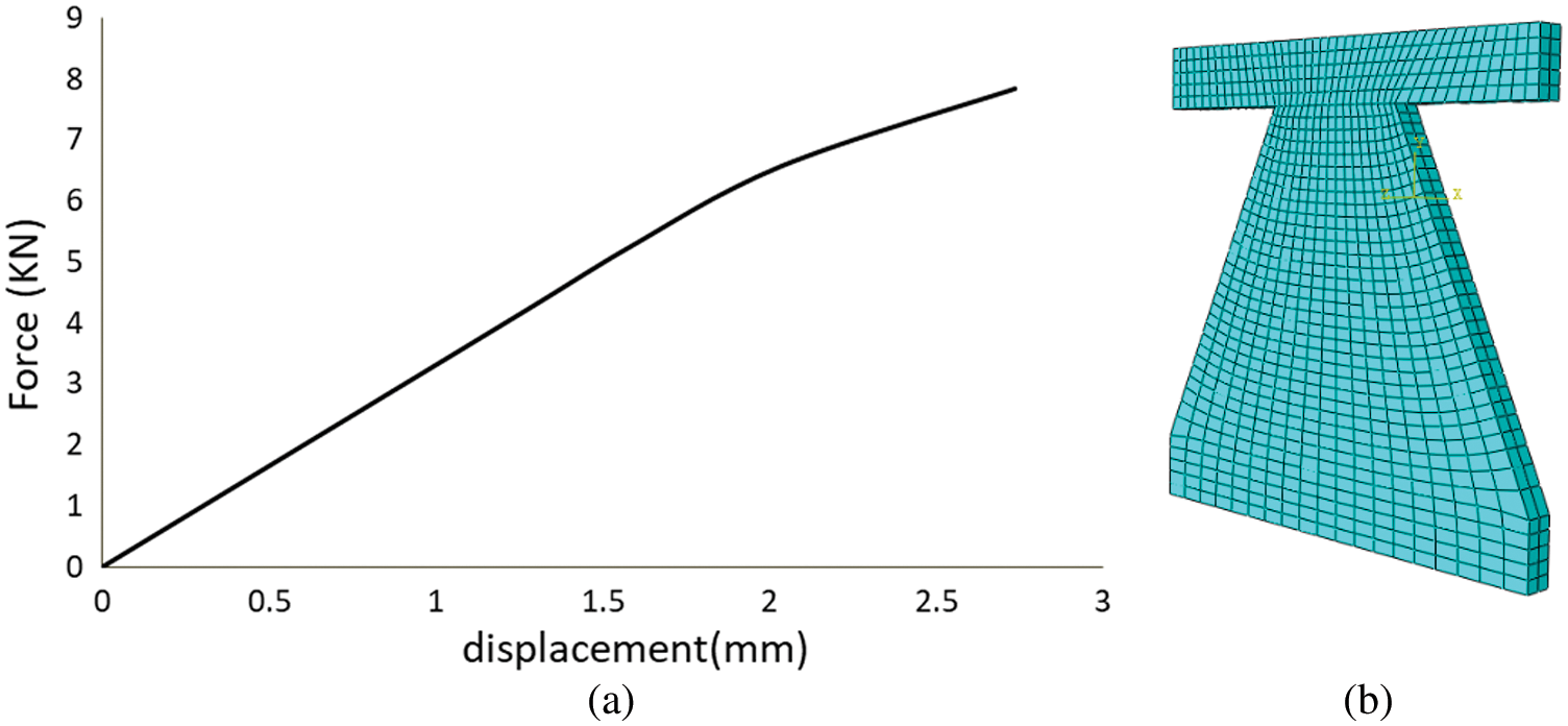
Figure 8: (a) Force-displacement diagram (b) Finite element model of the TADAS plate
The geometrical properties and young’s modulus of the steel affect the lateral stiffness of the TADAS plate. A closer look at Eq. (5) reveals that the initial stiffness of the plate is directly related to the young’s modulus of the steel, width of the plate, and the third power of the plate’s thickness. The initial stiffness of the TADAS plate is inversely proportional to the third power of its height. The same correlation can also be demonstrated for the shell element models. Fig. 9a shows the dimensions of the modeled TADAS. The pushover analysis and the stiffness of the TADAS plate were performed and obtained for different values of b, t, and h. Fig. 9b demonstrates the effect of different geometrical properties on the lateral stiffness of the TADAS plate. It can be seen that the lateral stiffness of the TADAS plate is directly proportional to t3 and inversely proportional to h3.
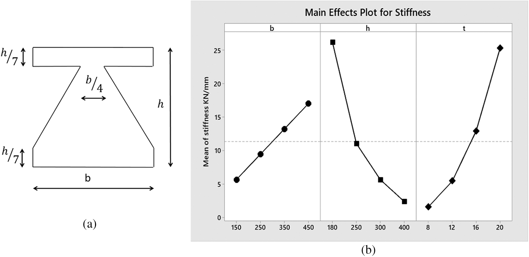
Figure 9: (a) Dimensions selected for the TADAS plate for the sensitivity analysis (b) Diagram of the effects of height, width, and thickness of the plate on the lateral stiffness TADAS damper
A dimensionless diagram is presented which shows the effective stiffness of the retrofitted RC frame as a function of the axial load of the columns and the lateral strength of the retrofitted RC frame (Fig. 10). To make this diagram, the stiffness and strength ratio of the retrofitted RC frame to that of the initial RC frame was used. Videlicet, the upper line in the diagram is related to the RC frame retrofitted with eight TADAS plates whose shear capacity is 3.81 times greater than that of the initial frame. The ultimate lateral strength of the moment resisting frame in the experimental model [24], study was reported to be equal to 39.6 kN. The results of this diagram can be very useful to surmise what the lateral stiffness of the RC frame equipped with TADAS is.
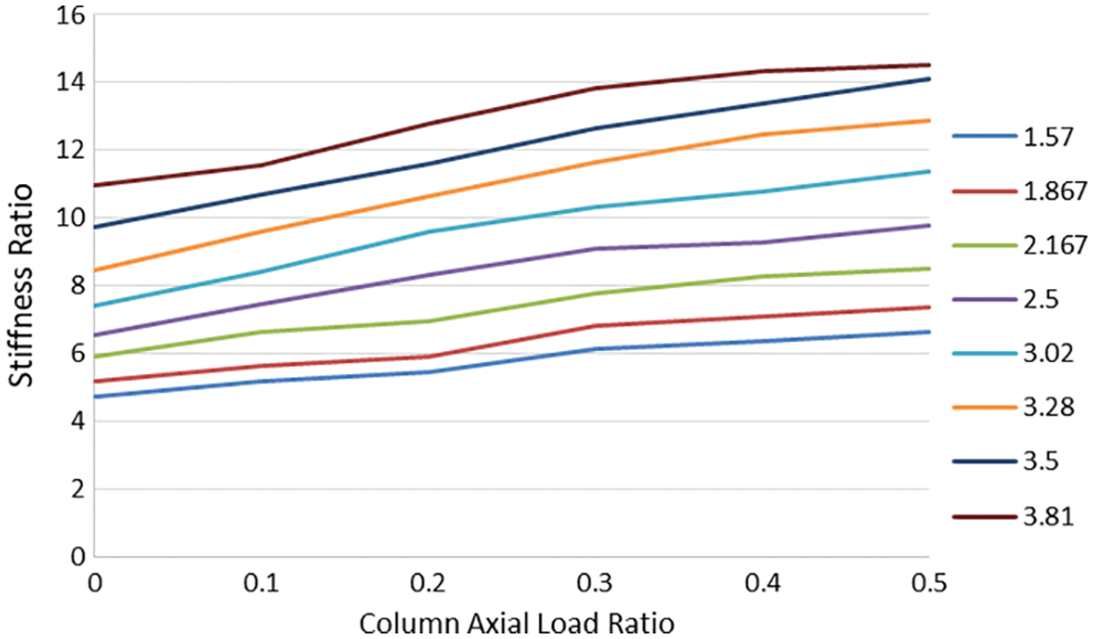
Figure 10: The rate of increase in the effective stiffness of the frame with respect to the increase in strength and column force
The effects of the number of TADAS damper and column axial force on the ultimate strength of the frame plotted in Fig. 11. It can be observed that by increasing the number of the dampers, the ultimate lateral strength of the RC frame has increased. The average of this increase for every TADAS plate is equal to 10.93 kN. The ultimate shearing capacity of a TADAS plate can be calculated using Eq. (7):
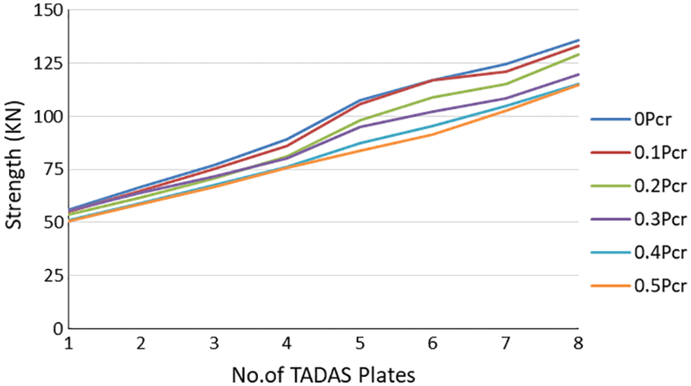
Figure 11: Ultimate strength of the model with respect to variation of TADAS dampers and column force
In which L represents the distance between locations at which plastic hinges have been created in the TADAS plate.
Values predicted by Eq. (7) are close to the ones obtained from the numerical analyses. The effect of axial force is more pronounced when the number of TADAS plates is bigger than 4, and the frame has had a decreasing ultimate lateral strength of almost 4.3 kN for a column axial force increase of 0.1 Pcr.
7 Parameters Affecting Ductility and Energy Dissipation
Figs. 12a and 12b show the effects of both the axial load of columns and the number of TADAS dampers on the ductility and dissipated energy of the model. As it can be observed, increase in the axial force of the columns has resulted in the ductility factor and dissipated energy of the frame being decreased. If the column axial force is greater than 0.2 Pcr, decrease in the ductility and dissipated energy of the frame is significant. When the number of the yielding plates is 5 or 6, a column axial force range of 0 to 0.2 Pcr would lead to the most suitable response by the structure. Therefore, based on Fig. 10, the shear capacity of the equipped frame is about 3 times that of the initial frame. In this case, one can be certain that the retrofitted structure has the highest energy dissipation and ductility.
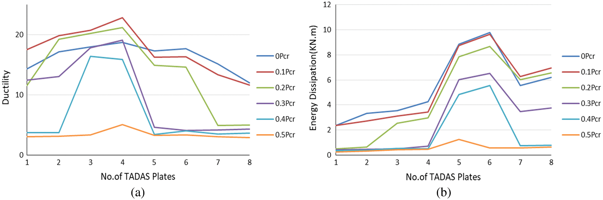
Figure 12: The effects of the number of TADAS dampers and increase in column axial force on (a) Ductility and (b) Energy dissipation
8 Case Studies RC Moment-Resisting Frames Equipped with TADAS Plates
We consider the structure shown in Fig. 13. A five-story RC structure with the story height of 3 m and intermediate RC moment resisting frame lateral systems on both directions is considered. Retrofitting is done for multiple reasons, the most important of which are change in seismic design standards, change in occupancy, adding stories to the structure, low quality of the concrete, and the poor stiffness and strength. It is assumed that the structure is in need of retrofitting. We assume that the structure is weak in the X direction and cannot withstand more than 50% of the lateral load proposed by seismic design standards. In each story, four bays along the X direction are retrofitted with Chevron braces and TADAS dampers. Side bays of the A and B frames are chosen to be retrofitted. The A and B frames of the retrofitted the structure are shown in Fig. 14.
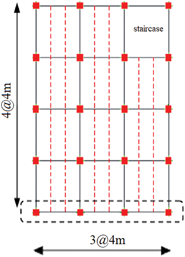
Figure 13: Plan of the considered structure
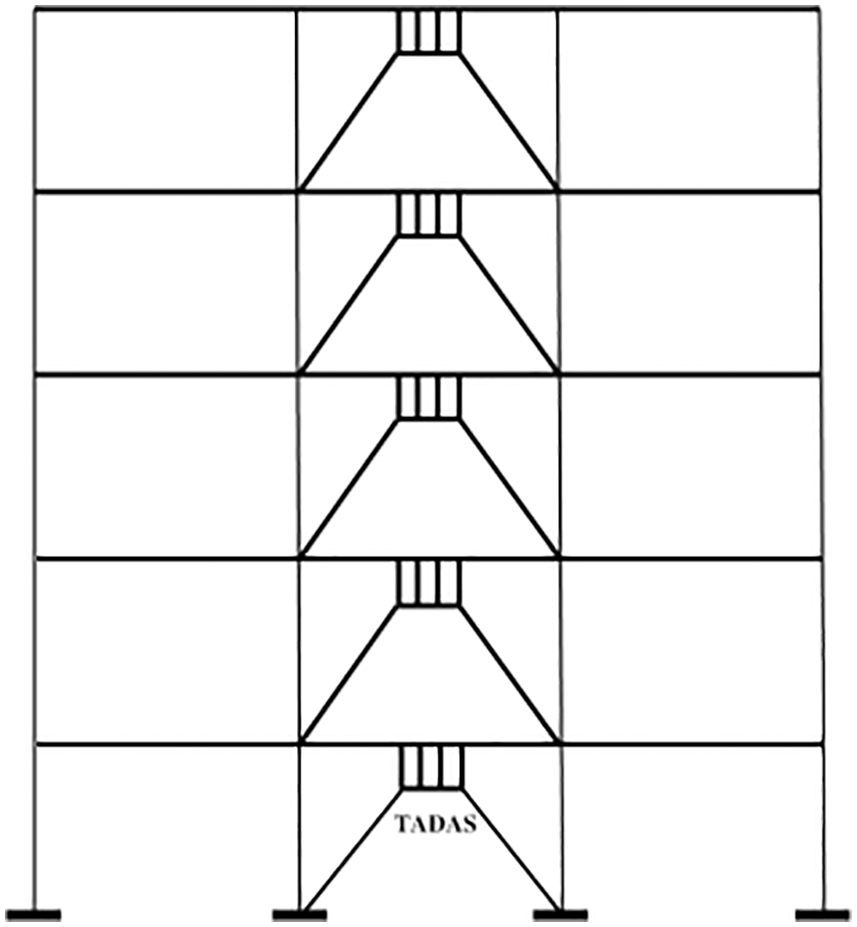
Figure 14: Views of the A and B frames of the structure
If the seismic weight of each story (including the entire of the dead load and a percentage of the live load) is equal to 2300 kN, the overall weight of the building would be equal to 11.500 kN. If the seismic coefficient of the structure is assumed to be 0.18, then:
The structure has been designed for an earthquake force of 1380 kN, meaning that the structure is 50% weaker. As previously mentioned, a structure equipped with TADAS dampers would display its best performance if the lateral strength of the retrofitted structure is three times bigger than that of the bare frame. In other words, the collective ultimate strength of the dampers has to be twice the shear force of the bare frame. So, the TADAS dampers in the ground floor in the X direction have to be able to withstand a force of 2 × 1380 = 2760 kN. The thickness of the TADAS dampers was 25 mm and their geometry is shown in Fig. 15. The specifications of the steel of the dampers were the same as the experimental models. Using Eq. (7), the ultimate shear force of each plate can be calculated as:
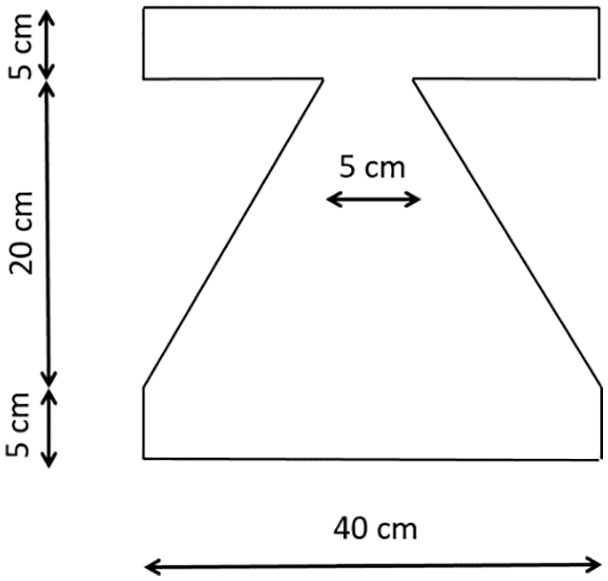
Figure 15: Dimensions of the retrofitting TADAS plates
Therefore, the total number of dampers needed would be 2760/124.3 = 22.2, which was rounded up to 24. In each Chevron race, six TADAS dampers were installed. The dampers of the first floor absorb the entirety of the shear force imposed by the earthquake. In the upper stories, the shear force attenuates and therefore fewer dampers are needed (Fig. 16). It has to be kept in mind that to calculate the number of TADAS dampers in the upper stories, one should be aware of the seismic design code used for the design of the structure, so that the earthquake force at each story could be calculated and the number of dampers could be determined on a pro rata basis.
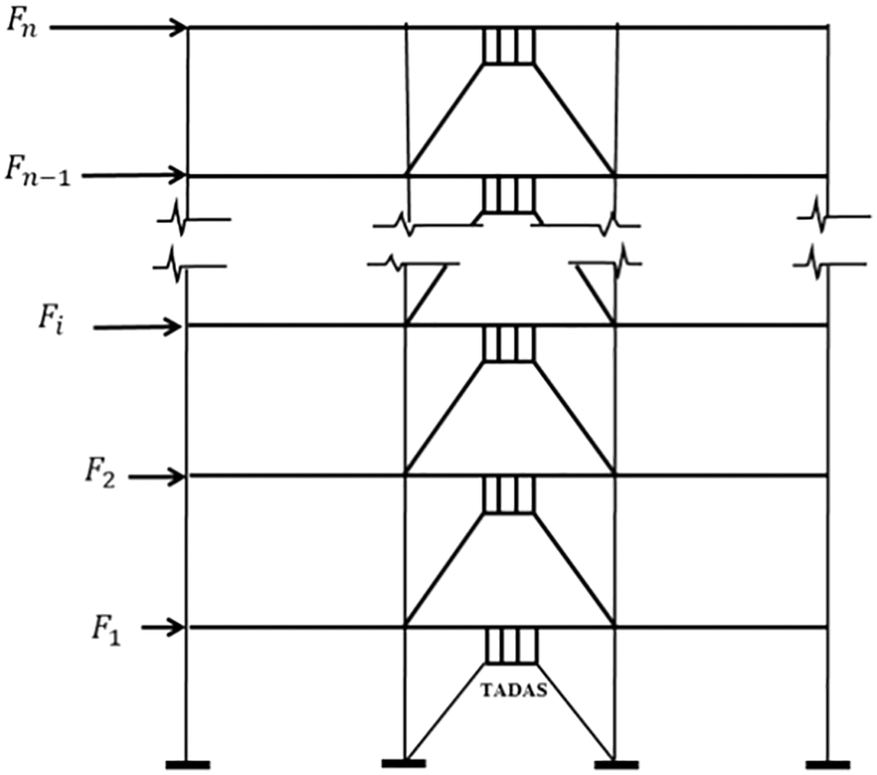
Figure 16: Seismic force at each story
The stiffness of each TADAS plate is calculated through Eq. (5) as follows:
For 24 dampers in the ground floor, the stiffness of the structure would increase by about 696 kN/mm. The following points should be paid attention to:
• Originally, the structure was 50% weaker than what was necessary for the withstanding the lateral forces. The lateral strength of the structure is now three times greater than the original state, meaning that from the lateral strength the standpoint, the structure is reliable.
• The profile of the columns and beams are known, the stiffness of the retrofitted structure can be obtained. Finally, by observing the drift of the structure, the efficiency (or lack thereof) of the added dampers in each story can be determined. Since the lateral strength of the retrofitted structure is about three times bigger than that of the bare frame, the stiffness of the structure has increased substantially. You structure, therefore, can safely absorb the drift of the stories.
• If the drift value is not satisfied, the number of the TADAS plates should be increased. In that case, the lateral strength of the retrofitted structure would be three times bigger than that of the original structure, effectively making the retrofitting scheme non-optimal. It is, therefore, better to strengthen the columns and beams of the original structure as well.
• By being aware of the axial force in the columns and their geometrical properties, Fig. 10 can be used to assess the stiffness, axial load of columns, and ultimate strength.
• The profile of the braces has to be chosen so that no buckling of any kind takes place.
• The praise connections have to be designed for force transmission. Due to the increase in the ultimate lateral strength of the frame, the foundation of the structure might be in need of strengthening.
In this study, an RC moment-resisting frames equipped with TADAS yielding plates were numerically investigated. Using calibrated numerical models and 48 pushover analyses, the effects of the number of TADAS plates and column axial load on the seismic behavior the concrete frame were investigated. Some theoretical formula were also presented to estimate the effect of the number of TADAS plates on the lateral stiffness and ultimate lateral strength of the frame. Eventually, the conclusions are listed below:
• The increasing rate of the effective stiffness of the frame with respect to the increase in the number of TADAS dampers is almost constant. A relationship describing the increase in the effective stiffness of the RC frame with respect to the increase in the number of the TADAS dampers was also presented.
• A dimensionless plot was introduced based on the variation of the column axial force and ultimate strength of the frame to calculate the amount of the relative effective stiffness of the retrofitted RC frame (Fig. 10).
• A formula was proposed to calculate, with appropriate accuracy, the increase in the ultimate strength of the equipped RC frame based on the number and thickness of the TADAS plates (Eq. (7)). This equation can be use for design purposes.
• The structure would be a desirable state if the axial force in the columns does not exceed 0.2 Pcr. A larger force in the columns brings about a sudden decline in the dissipated energy and ductility of the frame.
• The number of the TADAS plates has to be specified so that the ultimate strength of the retrofitted RC frame would three times bigger than the bare RC frame. In this case, it can be ensured that the ductility factor and energy dissipation would take on their maximum values.
Funding Statement: The authors received no specific funding for this study.
Conflicts of Interest: The authors declare that they have no conflicts of interest to report regarding the present study.
References
1. Kelly, J. M., Skinner, R. I., Heine, A. J. (1972). Mechanisms of energy absorption in special devices for use in earthquake resistant structures. Bulletin of NZ Society for Earthquake Engineering, 5(3), 63–88. DOI 10.5459/bnzsee.5.3.63-88. [Google Scholar] [CrossRef]
2. Stiemer, S. F., Godden, W. G., Kelly, J. M. (1981). Experimental behavior of a spatial piping system with steel energy absorbers subjected to a simulated differential seismic input. University of California, Earthquake Engineering Research Center. [Google Scholar]
3. Whittaker, A., Bertero, V. V., Alonso, J. (1989). Earthquake simulator testing of steel plate added damping and stiffness elements. Report No. 89/02. Earthquake Engineering Research Center, University of California, Berkeley, CA, USA. [Google Scholar]
4. Sebt, M. H., Yousefzadeh, A., Tehranizadeh, M. (2011). The optimal TADAS damper placement in moment resisting steel structures based on a cost-benefit analysis. International Journal of Civil Engineering, 9(1), 23–32. [Google Scholar]
5. Mahmoudi, M., Abdi, M. G. (2012). Evaluating response modification factors of TADAS frames. Journal of Constructional Steel Research, 71, 162–170. DOI 10.1016/j.jcsr.2011.10.015. [Google Scholar] [CrossRef]
6. Moghaddasi, M., Namazi, A. (2016). Assessment of performance of TADAS dampers for the seismic rehabilitation of buildings. International Journal of Applied Engineering Research, 11(21), 10516–10523. [Google Scholar]
7. Saeedi, F., Shabakhty, N., Mousavi, S. R. (2016). Seismic assessment of steel frames with triangular-plate added damping and stiffness devices. Journal of Constructional Steel Research, 125, 15–25. DOI 10.1016/j.jcsr.2016.06.011. [Google Scholar] [CrossRef]
8. Shojaeifar, H., Maleki, A., Lotfollahi-Yaghin, M. A. (2020). Performance evaluation of curved-TADAS damper on seismic response of moment resisting steel frame. International Journal of Engineering, 33(1), 55–67. [Google Scholar]
9. Houshmand-Sarvestani, A., Totonchi, A., Shahmohammadi, M. A., Salehipour, H. (2021). Numerical assessment of the effects of ADAS yielding metallic dampers on the structural behavior of steel shear walls (SSWs). Mechanics Based Design of Structures and Machines, 50(1), 1–19. DOI 10.1080/15397734.2021.1875328. [Google Scholar] [CrossRef]
10. TahamouliRoudsari, M., Cheraghi, K., Habibi, M. R. (2019). Investigation of retrofitting RC moment resisting frames with ADAS yielding dampers. Asian Journal of Civil Engineering, 20(1), 125–133. DOI 10.1007/s42107-018-0092-6. [Google Scholar] [CrossRef]
11. Khoshkalam, M., Mortezagholi, M. H., Zahrai, S. M. (2021). Proposed modification for ADAS damper to eliminate axial force and improve seismic performance. Journal of Earthquake Engineering, 27(1), 1–23. DOI 10.1080/13632469.2020.1859419. [Google Scholar] [CrossRef]
12. Alehashem, S. M. S., Keyhani, A., Pourmohammad, H. (2008). Behavior and performance of structures equipped with ADAS & TADAS dampers (a comparison with conventional structures). 14th World Conference on Earthquake Engineering, pp. 12–17. Beijing, China. [Google Scholar]
13. Akehashi, H., Takewaki, I. (2021). Ideal drift response curve for robust optimal damper design for elastic-plastic MDOF structures under multi-level earthquakes. Computer Modeling in Engineering & Sciences, 129(3), 1181–1207. DOI 10.32604/cmes.2021.017204. [Google Scholar] [CrossRef]
14. Bedon, C., Amadio, C. (2019). ADAS dampers for the hazard protection of multi-storey buildings with glazing envelopes: A feasibility study. Bollettino di Geofisica Teorica ed Applicata, 60(2), 197–220. DOI 10.4430/bgta0253. [Google Scholar] [CrossRef]
15. Kim, S. W., Kim, K. H. (2020). Evaluation of structural behavior of hysteretic steel dampers under cyclic loading. Applied Sciences, 10(22), 8264. DOI 10.3390/app10228264. [Google Scholar] [CrossRef]
16. Kheyroddin, A., Sepahrad, R., Saljoughian, M., Kafi, M. A. (2019). Experimental evaluation of RC frames retrofitted by steel jacket, X-brace and X-brace having ductile ring as a structural fuse. Journal of Building Pathology and Rehabilitation, 4(1), 1–13. DOI 10.1007/s41024-019-0050-z. [Google Scholar] [CrossRef]
17. Qian, K., Weng, Y. H., Li, B. (2019). Improving behavior of reinforced concrete frames to resist progressive collapse through steel bracings. Journal of Structural Engineering, 145(2), 04018248. DOI 10.1061/(ASCE)ST.1943-541X.0002263. [Google Scholar] [CrossRef]
18. ZerrinKorrkmaz, S. (2020). An analytical study about the use of steel plate shear walls to improve lateral rigidity of reinforced concrete framed structures. Latin American Journal of Solids and Structures, 17(7), 59–78. DOI 10.1590/1679-78256100. [Google Scholar] [CrossRef]
19. Sutcu, F., Bal, A., Fujishita, K., Matsui, R., Celik, O. C. et al. (2020). Experimental and analytical studies of sub-standard RC frames retrofitted with buckling-restrained braces and steel frames. Bulletin of Earthquake Engineering, 18(5), 2389–2410. DOI 10.1007/s10518-020-00785-4. [Google Scholar] [CrossRef]
20. Yu, J., Gan, Y. P., Ji, J. (2020). Behavior and design of reinforced concrete frames retrofitted with steel bracing against progressive collapse. The Structural Design of Tall and Special Buildings, 29(12), e1771. DOI 10.1002/tal.1771. [Google Scholar] [CrossRef]
21. Kafi, M. A., Kheyroddin, A., Omrani, R. (2020). New steel divergent braced frame systems for strengthening of reinforced concrete frames. International Journal of Engineering, 33(10), 1886–1896. [Google Scholar]
22. TahamouliRoudsari, M., Torkaman, M., Entezari, A. R., Rahimi, H., Niazi, K. (2019). Experimental investigation of strengthening reinforced concrete moment resisting frames using partially attached steel infill plate. Structures, 19, 173–183. DOI 10.1016/j.istruc.2019.01.009. [Google Scholar] [CrossRef]
23. TahamouliRoudsari, M., Entezari, A., Hadidi, M., Gandomian, O. (2017). Experimental assessment of retrofitted RC frames with different steel braces. Structures, 11, 206–217. DOI 10.1016/j.istruc.2017.06.003. [Google Scholar] [CrossRef]
24. TahamouliRoudsari, M., Eslamimanesh, M. B., Entezari, A. R., Noori, O., Torkaman, M. (2018). Xperimental assessment of retrofitting RC moment resisting frames with ADAS and TADAS yielding dampers. Structures, 14, 75–87. DOI 10.1016/j.istruc.2018.02.005. [Google Scholar] [CrossRef]
25. Jankowiak, T., Lodygowski, T. (2005). Identification of parameters of concrete damage plasticity constitutive model. Foundations of Civil and Environmental Engineering, 6(1), 53–69. [Google Scholar]
26. Kent, D. C., Park, R. (1971). Flexural members with confined concrete. Journal of the Structural Division, 97(7), 1969–1990. DOI 10.1061/JSDEAG.0002957. [Google Scholar] [CrossRef]
27. Park, R., Paulay, T. (1975). Reinforced concrete structures. NY, USA: John Wiley & Sons. [Google Scholar]
28. American Concrete Institute (2014). ACI, building code requirements for structural concrete (ACI 318-14) and commentary. Farmington Hills, MI: ACI. [Google Scholar]
29. FEMA-440 (2005). Improvement of nonlinear static seismic procedures. Washington, USA: Federal Emergency Management Agency, FEMA. [Google Scholar]
Cite This Article
 Copyright © 2022 The Author(s). Published by Tech Science Press.
This work is licensed under a Creative Commons Attribution 4.0 International License , which permits unrestricted use, distribution, and reproduction in any medium, provided the original work is properly cited.
 Downloads
 Citation Tools