
 Submit a Paper
 Propose a Special lssue
 Open Access
ARTICLE

Vibration Characteristics Analysis and Structure Optimization of Catenary Portal Structure on Four-Wire Bridge
1 School of Automation & Electrical Engineering, Lanzhou Jiaotong University, Lanzhou, 730070, China
2 Rail Transit Electrical Automation Engineering Laboratory of Gansu Province (Lanzhou Jiaotong University), Lanzhou, 730070, China
* Corresponding Author: Xujie Li. Email:
Structural Durability & Health Monitoring 2022, 16(4), 361-382. https://doi.org/10.32604/sdhm.2022.023851
Received 17 May 2022; Accepted 23 June 2022; Issue published 03 January 2023
 View Full Text
 Download PDF
Abstract
The portal structure is the support equipment in the catenary, which bears the load of contact suspension and support equipment. In practical work, with the change of external forces, the support equipment bears complex and changeable loads, so it has higher requirements for its reliability and safety. In order to study the dynamic characteristics of catenary portal structure on continuous beam of four-way bridge, taking the catenary portal structure on Dshaping four-way bridge as the research object, the portal structure simulation model of bridge-network integration was established in Midas Civil. The maximum point of deformation and stress was determined by finite element analysis of catenary hard span equipment, and the frequency and mode of natural vibration of hard span were obtained by modal analysis. Secondly, through the field dynamic stress acquisition test, combined with the results of finite element analysis, the fault location is determined, and the vibration characteristics are analyzed. Finally, based on the results of modal analysis and vibration analysis, the method that the vibration of portal structure beam is affected by structural stiffness and vibration frequency amplitude is proposed. The torsional vibration of the portal structure beam was suppressed by increasing the stiffness of the beam and reducing the vibration conduction between the trolley and the beam, and the hard cross beam was optimized by strengthening the hanging column and the connecting beam and adding diagonal support between the pillar and the portal structure beam. By comparing the values of shear, bending moment, displacement and dynamic stress on the hard span before and after optimization, the amplitude peak after structural optimization is reduced by about 25%, and the application of oblique support and reinforcement of the beam can significantly improve the portal structure vibration.Keywords
Lanzhou-Chongqing Railway is a double-line electrified passenger-freight rapid transport line in China. At the Dashaping large bridge of Lanzhou junction section of new railway Line from Lanzhou to Chongqing, it was found that the vibration of the bridge itself and catenary net will be caused when the four upstream lanes of Dashaping station passed through, and the catenary hanging string on box girder will be broken for many times, and even the portal structure connecting bolts will be loose or even broken. There are many factors that cannot be ignored in the force analysis of portal structure [1]. Therefore, the analysis of portal structure vibration characteristics based on finite element method is of great significance to the safe operation of catenary.
The catenary system is the core part of electrified railway, the stable contact and interaction between the pantograph and contact line is also the most important condition for safe power supply. The stability and safety of catenary portal structure is the important condition to ensure good train operation [2]. The stability and safety of catenary power supply of electrified high-speed railway lines can be effectively guaranteed by doing a good job in the research of catenary portal structure vibration [3,4]. The portal structure not only bears the dynamic lift force between the pantograph and the contact line, but also bears the axial force transmitted to the strut by the bull foot foundation of the strut [5,6]. The portal structure is subjected to complex and variable loads. When the frequency of vibration and shock between pantograph and net is close to the natural frequency of the portal structure beam when the railway wagon is running, the resulting coupling resonance will affect the portal structure reliability [7,8]. The catenary system is the core part of electrified railway, the stable contact and interaction between pantograph and contact line is also the most important condition for safe power supply. The stability and safety of catenary portal structure is the important condition to ensure good train operation. The stability and safety of catenary power supply of electrified high-speed railway lines can be effectively guaranteed by doing a good job in the research of catenary portal structure vibration [3,4]. The portal structure not only bears the dynamic lift force between the pantograph and the contact line, but also bears the axial force transmitted to the strut by the bull foot foundation of the strut [5,6]. The portal structure is subjected to complex and variable loads. When the frequency of vibration and shock between pantograph and net is close to the natural frequency of the portal structure beam when the railway wagon is running, the resulting coupling resonance will affect the portal structure reliability [7,8]. The portal structure vibrations can be studied with the help of simulation models. The models help to identify the dynamic behavior of the pantograph and the interaction phenomena in the pantograph-catenary system due to dynamic forces. The wind field force is applied to each object of the pantograph as a nonlinear force varying over time. These winds can be tested using computational fluid dynamics or experiments in wind tunnels [9–11]. The mathematical model of dynamic interaction between pantograph and catenary is simulated to benchmarking the interaction between pantograph and catenary. The model is able to study the vibration of the system over a relatively wide frequency range (up to 100 Hz), and the method reproduces the pantograph-catenary interaction with high accuracy over a wide frequency range. The test results are discrete, and the best modeling method for studying pantograph-catenary interaction is determined [12,13]. The simulation is done with an efficient finite element catenary model and a suitable impedance control architecture is designed. The model simulates a coupled resonance, showing high accuracy, high fidelity of the catenary model and closed loop testing of the pantograph model contacts Simulation performance of the console settings. The simulation compares model and pantograph model [14–16]. In beam vibration reduction technology. The tuned mass dampers are used to reduce vibration induced by external loads on beams. The simulation and experiments were conducted to verify the fundamental frequency of TPD at different spans, and forced vibration experiments with different excitation frequencies were also carried out. The tuned mass damper effectively suppressed the vertical vibration of the structure at different excitation frequencies [17,18]. In catenary detection technology. Shigeyuki adopts the dynamic substructure system method to test the performance of railway pantograph-catenary system. The condition of the maintenance catenary system can be effectively detected by detecting wear and other damage phenomena. The experimental dynamic substructure system test results are compared with simulation results from a benchmark pantograph-catenary simulation system, and the limitations of currently used measurement methods are highlighted [19,20].
The existing research results mainly focus on the vibration characteristics of the portal structure of the catenary on the ground. There were fewer studies and analyses of the portal structure of the catenary on the bridge. Motivated by the insufficiencies mentioned above, this paper designs a special catenary portal structure dynamic stress calculation model on the special bridge based on the portal structure of the catenary on the DashapingTe Bridge. Considering the bridge-catenary coupling resonance effect under the action of vehicle, the effect of different speeds and weights of trucks on the vibration response of portal structure is compared and analyzed. Modal analysis is used to calculate the frequency and mode of the portal structure inherent vibrations, combined with on-site portal structure load tests. The vibration response of the hard span before and after the optimization of the transformation is studied, which provides a reference basis for the vibration reduction of the portal structure of the catenary on the four-wire bridge.
2 Finite Element Analysis of Catenary Portal Structure
2.1 3D Model of Catenary Portal Structure on Continuous Beam
The Dashapingte Bridge is located in the Lanzhou hub section of the Lanzhou-Chongqing Railway. Through observation, it is found that the bridge vibrates strongly at the prestressed concrete continuous box girder (40 + 64 + 40) m when the railway wagon is running, especially at the continuous box girder. The catenary swayed very seriously, and the safety hazards of loose bolts and bolts falling off at many hard beams were found. It has also caused the catenary suspension string to shake and break many times. Over time, under the frequent shaking, the bolt is loosened, and the bolt is cut under the action of shear force, and there is a major safety hazard for the hard beam to fall off.
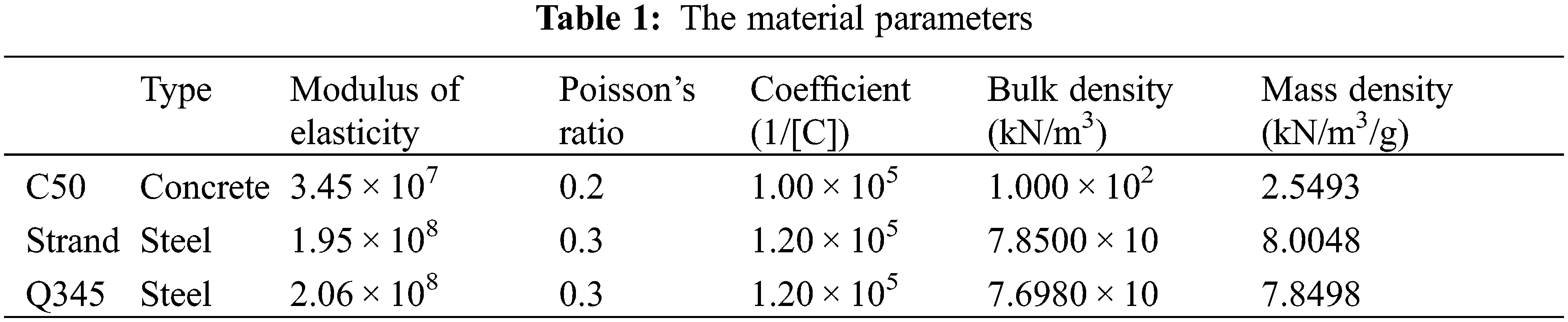
The continuous beams of the Dashapingte Bridge are designed in a straight line, and the left and right continuous beam beams are single-box, single-chamber variable height straight-web box-type cross-sections. The top of the continuous girder section bridge stretches out horizontally to make a platform. The continuous beam segment catenary pillars are fixed on this platform. The catenary is a hot-dip galvanized lattice structure of hard beam and equal diameter steel pipe column structure, the lower part is fixed to the lower chord rod, the positioning support adopts the hanging column method, and the fork area adopts the hard beam plus positioning cable structure. Using finite element to calculate hard across vibrations is a lot of work. In order to ensure the accuracy of the finite element calculation, additional components such as nuts and gaskets configured for specific use requirements in the field are ignored, and features with less impact on connection, structural deformation and center of gravity displacement are omitted. The main material used in the modeling is C50 concrete, the steel is Q345, and the parameters of the model material are shown in Table 1.
2.2 Span Structure Finite Element Network Model
Midas Civil was used as a tool for hard span finite element simulation. Midas Civil is a versatile, state-of-the-art finite element simulation software for structural analysis and design of Bridges. It is used to analyze the natural vibration of structure and simulate the stress state of rigid bridge. The internal force, stress and displacement of the structure are obtained by simulation, and the vibration of the structure is analyzed [21,22]. The cross section of the bridge is a single box and single chamber box girder. The transverse and horizontal beam connections and beams are simulated by hinged beam element, the cable element is simulated by tension only, and the steel column by tension only truss element. The positioner is mainly simplified to the displacement constraint of the centralized mass element and the vertical direction. The wrist arm structure is mainly simplified to the displacement constraint in the transverse direction and vertical direction. The tension compensator is simplified to a constant tensile load. The force-bearing cable, contact line, and elastic sling are simplified to the beam elements of the beam structure. The calculation converts the portal structure of the self-weight into a specific force, sets the value, and gives the structure its own material and corresponding cross-sectional characteristics. The simulation calculation model of catenary bridge was established, including 1598 nodes and 2802 units. The 3D model and finite element calculation model of the special catenary portal structure system are established in Midas Civil by means of a special connection method with a continuous beam, as shown in Figs. 1 and 2.
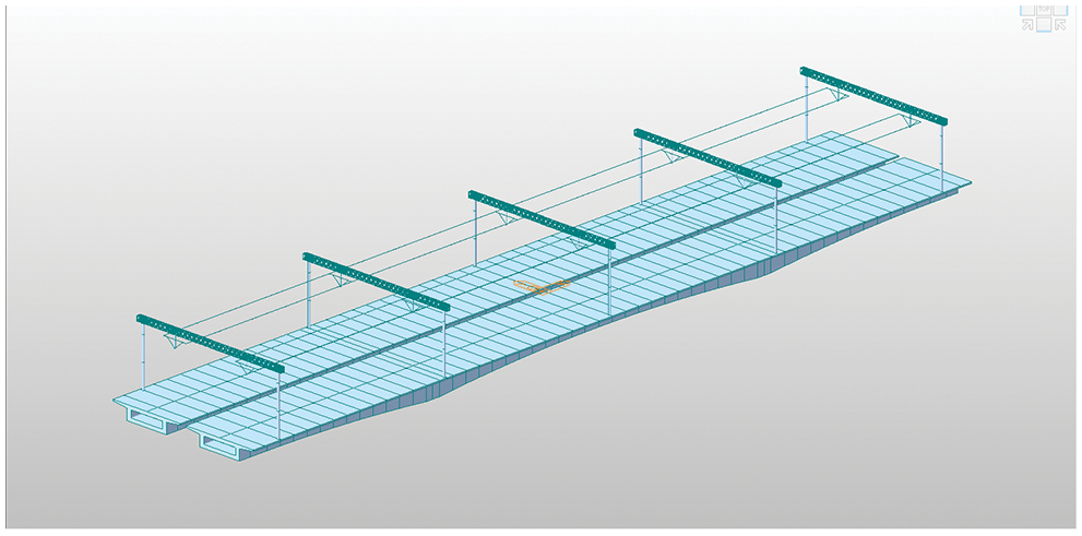
Figure 1: 3D model of bridge-net portal structure
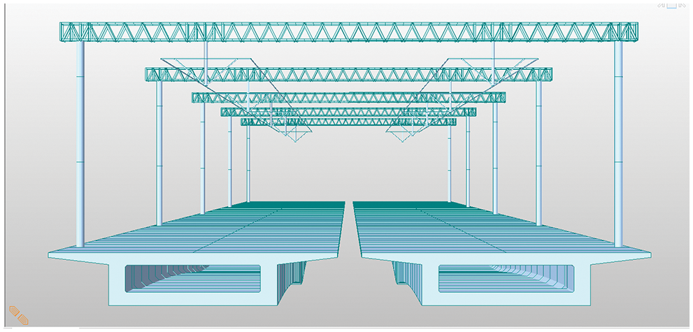
Figure 2: Finite model
2.3 Material Properties of Portal Structure
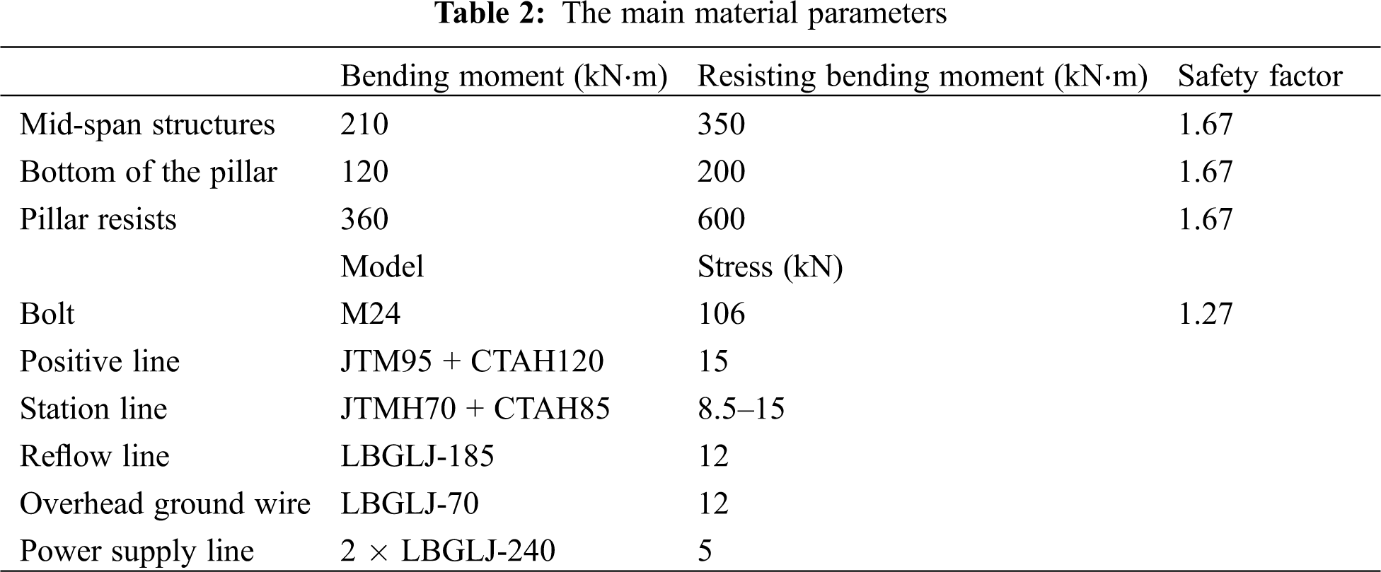
The catenary span structures on the Dashaping Bridge mainly include: the bridge structure is (40 + 64 + 40)m prestressed concrete continuous box girder bridge, the bearing adopts TPZ basin rubber bearing, and the beam is ordinary carbon Plain structural steel Q345. The lead steel of the beam is ∠80 × 8, the connecting bolts of the beam are M24, and the connecting bolts of the beam and the pillar are M30; the steel column is an equal diameter steel pipe column with an outer diameter of 350 mm and a wall thickness of 14 mm. Due to the specific use of the site, the additional components required to be configured and the fatigue analysis process have little impact on the whole, so they can be ignored. The main material parameters of the overall structure are shown in Table 2 below.
2.4.1 Static Load Loading Analysis
The static load is the shear force and axial force generated under the influence of its own weight, suspended vertical load, etc., under the working condition of no external influence, and all the bending moments and axial forces are borne by the catenary. The portal structure caused by shear stress is greater than the axial force caused by stress. To simplify the analysis, only the effect of shear force on the hard span is analyzed [23,24].
In the rigid catenary system, the contact line, the elastic clip and the weight of the beam itself are loaded on the portal structure device by hanging, which is mainly the vertical load. The clue device is connected to the suspension davit by a rotating base, which acts as a fixation on the portal structure. Therefore, it is necessary to apply fixed constraints to the hanging site when modeling. The clue device and portal structure their own weights are loaded by gravitational acceleration to initialize the model. After initialization, the portal structure is a transverse arm beam structure, so the force in the portal structure is more concentrated, as shown in Fig. 3. The maximum deformation is 1.162 mm, which is located in the middle of the portal structure beam, as shown in Fig. 4. The portal structure can be approximated as a beam structure, and the beam span is most likely to produce the largest amount of deformation, but this deformation fully meets the design requirements.
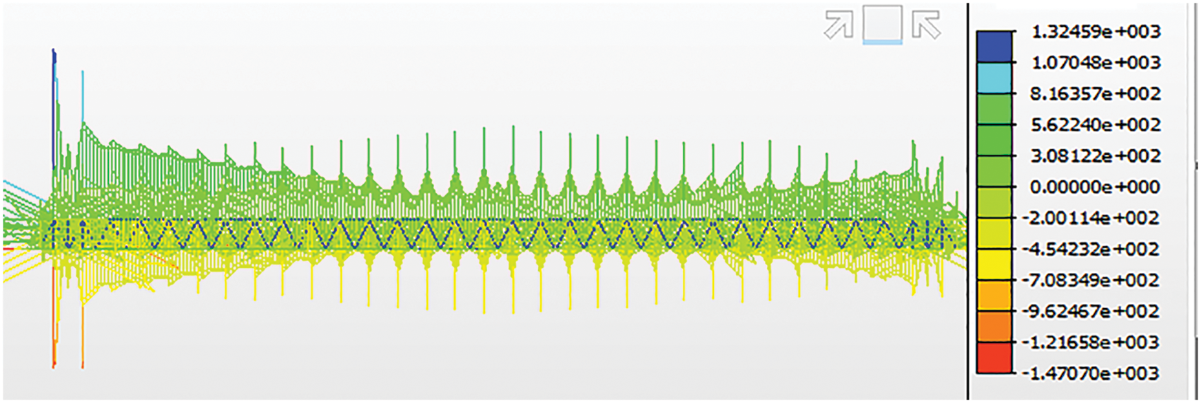
Figure 3: Stress cloud image under static load

Figure 4: Displacement diagram under static load
2.4.2 Dynamic Load Loading Analysis
Dynamic load refers to the continuous change of external load with time, which can be a regular change, such as a harmonic signal. In general, it can be expressed in terms of a function, or it can be defined in terms of data points. In this paper, the random load-time history of the catenary is loaded with the lifting force at different speeds and weight levels obtained from the dynamic simulation of the railway wagon, and the loading position is the portal structure beam. The dynamic load generated during the operation of the railway wagon and the load that the railway wagon will generate during driving can be composed of excitation function, static load and railway wagon vibration series functions [25,26]:
where is the load force of
where, m is part of the mass of the railway wagon when it is acting;
The frequency related to the vibration wavelength of the railway wagon load and the hard span structure is:
where,
According to JTG/D60-2015, “Bridge General Design Variable Force” and “Bridge Structure Calculation Midas Civil Design,” calculate the different speed and weight of the railway wagon in the initial state. According to the above calculation, set the constantly changing impact coefficient to simulate the pantograph model to simulate the running condition of the railway wagon.
Analytical hard traverse displacement, deflection and stress of the railway wagon at different speeds (120, 105, 85, 65, 45 km/h) [27,28]. Taking 85 km/h as an examples an example, the hard spanning displacement and stress nephogram of the catenary are shown in Fig. 5 below.

Figure 5: Cloud image of catenary portal structure at 85 km/h
The maximum displacement and stress of the catenary under the action of different railway wagon speeds (120, 105, 85, 65, 45 km/h) are shown in Table 3 below.
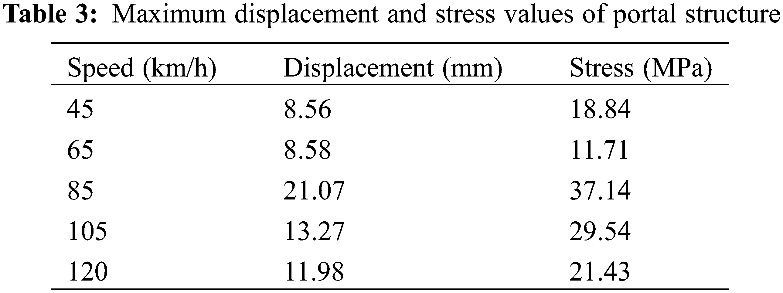
From the analysis of the simulation results in Fig. 3 and Table 1 above, it can be concluded that the maximum deformation of the portal structure displacement is mainly concentrated in the span, and the displacement deformation of the rest of the position supported by the pillar is basically unchanged. The maximum deflection of the portal structure beam is 21.07 mm. The maximum stress of the portal structure is at the connection between the catenary pillar and the beam and the two parts of the beam portal structure, and the maximum stress is 37.14 MPa. From the simulation analysis, it can be seen that when the railway wagon runs at a speed of about 85 km/h, the catenary rigid span is subjected to the largest mid-span deflection and stress.
3 Span Structures Modal Analysis
3.1 Modal Theoretical Calculation and Analysis
Modal analysis analyzes the vibration form and resonance properties of the vibration structure under the natural frequency state by obtaining the system modal parameters of the structural vibration, namely the natural frequency, modal frequency and modal shape, and researches the structural vibration characteristics and structural optimization of the structure theoretical basis is provided. According to the vibration equation of the rigid structure [29], the coupling equation of the spanning structure and the railway wagon can be expressed as follows. When using finite element analysis, the vibration equation of the hard span is:
Among them, [M] is the hard-span mass matrix, which is the diagonal matrix; [C] is the hard-span total damping matrix; [K] is the matrix sum of the element stiffness,
In the finite element modeling process, the hard spans are selected according to the structural elements. The phenomenon of vibration of hard spanning structure is only related to its own characteristics, which is the inherent frequency and mode shape characteristics of stiff spanning structure. According to the model, the unit vector:
The phenomenon of vibration of a spanning structure is only related to its own characteristics, which are the inherent frequency and mode shape characteristics of a rigid spanning structure:
where,
The sine term in the formula is any number and can be eliminated. To obtain the free vibration with finite amplitude, first let the determinant of the coefficient term in Eq. (7) be zero, and then Eq. (8) of the natural vibration frequency of the structure with portal structure can be obtained:
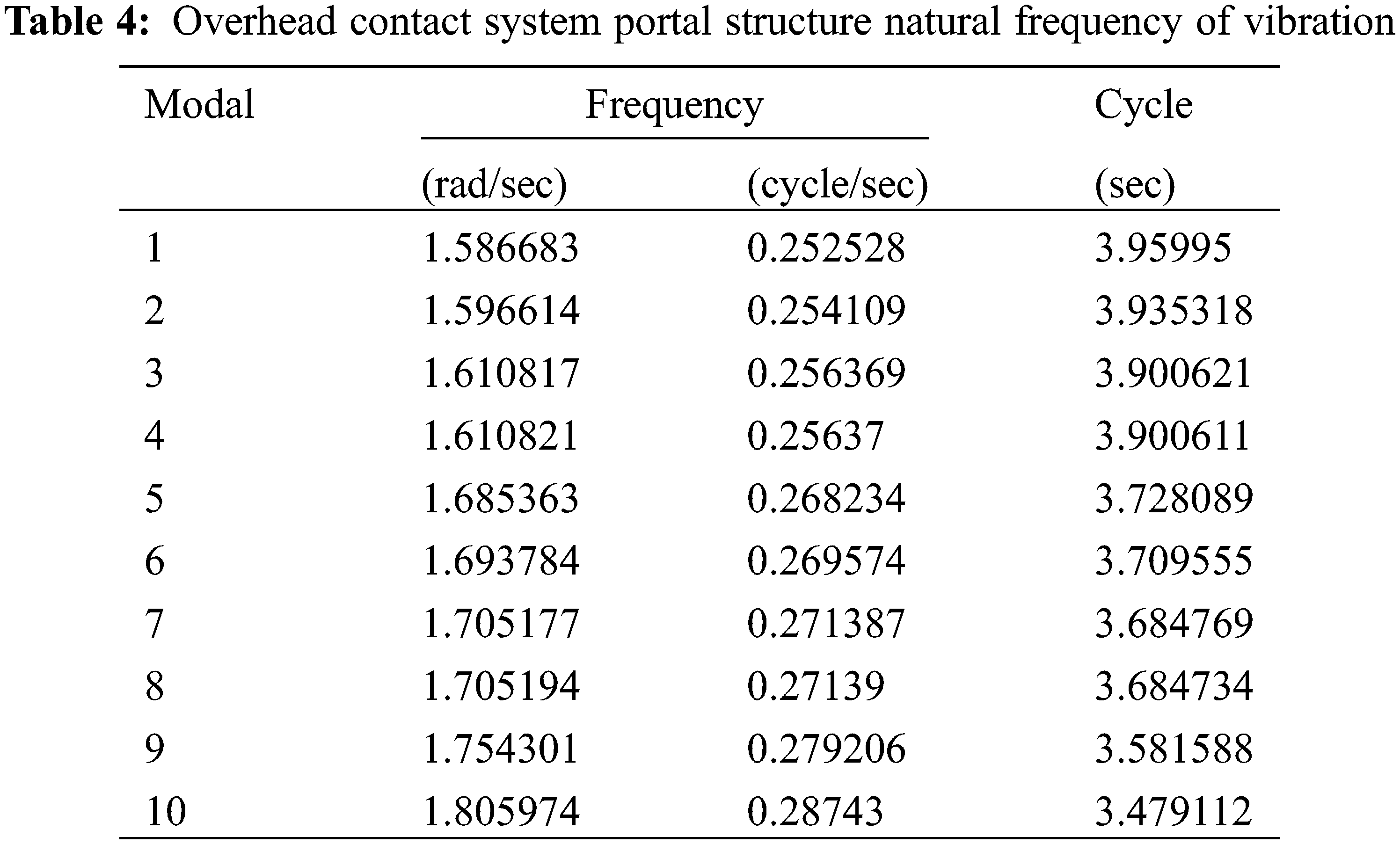
The first 10 frequencies of portal structure can be obtained by calculating the equations as shown in the Table 4 below.
3.2 Modal Theoretical Calculation and Analysis
According to the standard and design specification of the catenary span structures, it is simplified and analyzed; only the low-order frequency natural vibration characteristics of the catenary portal structure are analyzed, and the first 6-order elastic body modal vibration is extracted after removing the unsuitable 4-order rigid body mode [31,32]. The type is shown in Fig. 6.

Figure 6: The continuous beam catenary portal structure natural vibration mode
The catenary of the first and second modes has a tendency to oscillate longitudinally across the portal structure, and the amplitude is small, which is manifested as longitudinal vibration of the pillars and beams. The span of the portal structure has a more important influence on the vibration of the beam. The second mode type hard straddle vibrates vertically downward, the third mode type hard straddle beam vibrates vertically upwards, and there is basically no horizontal amplitude. The vertical vibration of the beam causes the contact clues to dance, which has a certain impact on the flow of the train. Measures such as increasing the stiffness of the beam-column connection or adding pillars should be taken to increase its stiffness. The fifth and sixth mode types are catenary portal structure the beam torsional vibration, which is caused by the portal structure the torsional resonance caused by the vehicle, and the mode continues to increase with frequency.
4 Analysis of Vibration Characteristics of Portal Structure
4.1 Portal Structure Dynamic Load Acquisition Test
In the load test of catenary portal structure, the measuring point should be selected at the position of the maximum deformation and the position of the maximum bending moment. Before the test, the faults generated in the actual work of the catenary system on the Dashaping Bridge were first investigated, summarized, and observed through observation and on-site observation. Through observation, it is determined that the continuous vibration of the hard span in the actual working process causes the largest vibration amplitude and the most serious damage in the middle part of the beam of portal structure, and some connecting bolts are loose or even broken and fall off. In addition, the maximum deformation position and the maximum bending moment point on the beam are selected as test points through finite element simulation analysis [33,34]. The test railway wagon has a hard-across the beam when it crosses the bridge with a force response value , and vertical, transverse, and longitudinal vibration sensors are arranged in the middle of the beam span, with the test measurement points shown in Fig. 7 and the field test diagram as shown in Fig. 8.
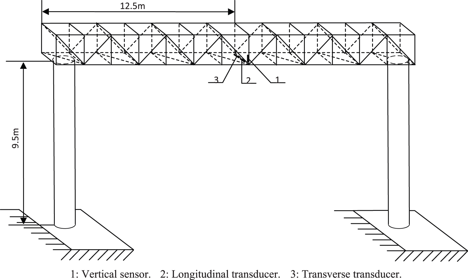
Figure 7: Schematic diagram of measuring point layout

Figure 8: Test site working diagram
4.2 Analysis of Dynamic Load Data
The test selects up and down railway wagons with a speed of 45 kM/h, and uses ZD-760 dynamic data to collect and analyze the vibration time domain waveform and related dynamic parameters of the rigid beam mid-portal structure when the railway wagon passes through the bridge.
The test process under different working conditions is shown in Fig. 9.

Figure 9: Test results of vibration amplitude of measuring point
It can be seen from the figure that when the railway wagon passes through a single lane at 45 km/h, regardless of whether it is going up or down, the maximum vertical vibration amplitude of the rigid beam is 3.0 mm, and the maximum longitudinal vibration amplitude is 4.5 mm; it can be seen from Fig. 9 that, the vibration amplitude of the rigid beam increases significantly when the railway wagon passes through parallel at 45 km/h. At the moment when the railway wagon is going up and down, the vertical and longitudinal amplitudes of the rigid beam are several times the maximum when passing through a single lane. Fig. 5e shows the maximum longitudinal amplitude of the rigid beam obtained from the test, reaching 21.08 mm. From the figure, it can be concluded that the maximum value when the up and down railway wagons converge is basically the same as that of the single-lane passage. It can be seen that when the railway wagons pass through multiple lanes at the same time, the vertical vibration of the rigid beam has a greater impact.
4.3 Analysis of Vibration Characteristics
Combined with the field dynamic load vibration amplitude acquisition test and finite element simulation analysis results, it can be seen that the large vibration of the portal structure will affect the fracture of the catenary rigid beam bolt. After long-term fatigue and damage operations, the bolt material and structure will eventually break through fatigue. limit, life will expire.
In the test, the main frequencies of portal structure vibration caused by the change of railway wagon operation are 45.86–80.59 Hz, which are close to the natural frequency corresponding to the fifth-order mode of portal structure natural vibration, which is a torsional mode, which is easy to cause torsional resonance of the beam. Therefore, it is necessary to study the optimization scheme to improve the natural frequency of the hard span mode.
4.4 Simulation Analysis of Portal Structure Vibration
Analyze the hard span bending moment, shear force, displacement, deflection and stress of the railway wagon under different weights; taking 70 T as an example, the portal structure bending moment, displacement and stress cloud diagram of the catenary is shown in Fig. 10 below.

Figure 10: Cloud view of overhead contact system portal structure at 70 T weight
The maximum bending moment, displacement and stress values of the catenary portal structure under the action of different railway wagon weights are shown in Table 5 below.
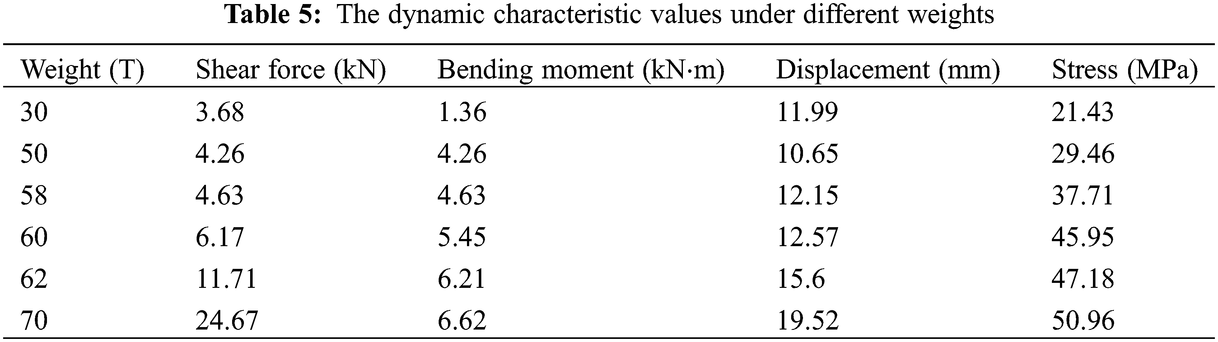
From the simulation results in Fig. 10 and Table 5, it can be seen that the bending moment and shear force on the portal structure of the catenary are mainly concentrated at the catenary pillar, and the distribution of the bending moment is small and uniform in other positions. The maximum bending moment and shear force are 6.62 kN m and 24.67 kN, respectively. The stress on the portal structure of the catenary is also mainly concentrated in the two parts of the catenary pillar and the middle span of beam, and the stress distribution of the portal structure is uneven, and the maximum stress is 50.96 MPa. The rest of the positions are affected by the catenary-pantograph to produce a small displacement at the hanging place, and the maximum deflection is 19.52 mm. It can be seen that the bending moment, shear force, mid-span deflection and stress of the catenary portal structure are greater when the railway wagon runs with a heavier load.
4.5 Comparative Analysis of Experiment and Simulation
For the action of uplink and downlink railway wagon at different speeds, ZD-760 dynamic data is used to collect the vibration time domain waveform of the catenary when the train passes through the bridge, and the related dynamic parameters are shown in Fig. 9. It can be seen from Fig. 9 that the main frequency of portal structure vibration caused by the change of railway wagon operation is between 45.86–80.59 Hz, which is close to the natural frequency corresponding to the fifth mode of portal structure natural vibration, 36.05177–70.15194 Hz, which is easy to cause torsional resonance of the beam. When the two vehicles pass in parallel at the same time, the vibration amplitude of the hard beam increases significantly. At the moment when the truck meets on the upper and lower sides, the vertical and longitudinal amplitude of the hard beam is up to several times that of the single lane. The test obtained the maximum value of the longitudinal amplitude of the hard beam, reaching 21.08 mm.
Midas Civil simulation is used to obtain the dynamic stress values (bending moment, shear force, displacement, deflection and stress) of the portal structure of the railway wagon as it crosses the bridge are obtained as shown in Fig. 8 and Table 3. The simulation results can be seen that the bending moment and shear force affected by the catenary portal structure are mainly concentrated at the catenary pillar, and the bending moment distribution in the remaining positions is small and relatively uniform. The stress on the portal structure of the catenary is also mainly concentrated in the two parts of the catenary pillar and the middle span of beam, and the stress distribution of the portal structure is uneven, and the maximum stress is 50.96 MPa. The other positions are affected by catenary-pantograph to produce a small displacement in the lifting place, and the maximum deflection is 19.52 mm.
The comparative test and simulation data are shown in Table 6. The test results show that the frequency is concentrated between 45.86–80.59 Hz, and the natural frequency corresponding to the fifth-order mode of portal structure natural vibration is between 36.05177–70.15194 Hz, which is basically close to each other. The frequency generated when the railway wagon passes corresponds to the portal structure 5th-order self-resonant 5th-order natural frequency, which is easy to lead to the torsional resonance of the portal structure. The maximum amplitude of the hard beam obtained by the test is 21.08 mm, which is slightly larger than the simulated value. Therefore, it is necessary to study the optimization scheme for improving the portal structure natural frequency.

5 Portal Structure Optimization and Simulation Verification
According to the above results of the above-mentioned modal analysis and vibration analysis of portal structure, combined with the reference data of the damaged position of the connecting bolt provided by the power supply bureau, it is determined that the continuous vibration of the portal structure in the actual working process causes the portal structure to have the largest vibration amplitude and the most serious damage. Based on the method of catenary portal structure the beam vibration is affected by structural stiffness constraints and vibration frequency amplitudes, by increasing the beam stiffness and reducing the vibration conduction between the vehicle-beam, the torsional vibration of the hard beam is suppressed, and Select a column to reinforce the connecting beams and add diagonal support between the pillars and the portal structure beams, as shown in Fig. 11 below. Site construction reinforcement Fig. 12.

Figure 11: Portal structure reinforcement model of overhead contact system

Figure 12: Portal structure reinforcement model of catenary
5.2 Simulation Analysis of the Effect of Railway Wagon Speed on Optimized Hard Traverse Vibration
Analysis of rigid spanning moment, shear force, displacement, deflection and stress of the catenary after reinforcement under the action of different speeds of the railway wagon; taking the speed of 85 km/h as an example, the bending moment, displacement and stress cloud diagram of the catenary portal structure As shown in Fig. 13 below.

Figure 13: Cloud image of catenary portal structure at 85 km/h
The maximum bending moment, displacement and stress of the reinforced catenary under the action of different railway wagon speeds (120, 105, 85, 65, 45 km/h) are shown in Table 7.
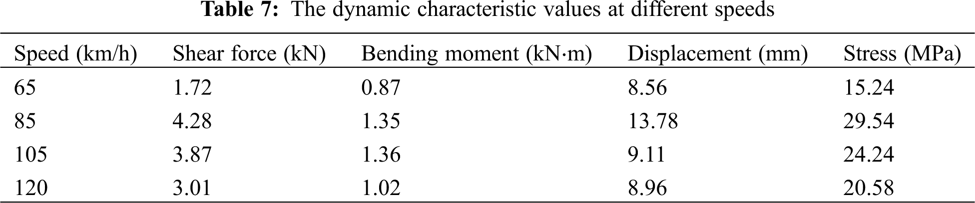
It can be seen from the simulation results in Fig. 13 and Table 4 that the maximum bending moment, shear force, mid-span deflection and stress of the reinforced catenary portal structure are inconsistent with the original position, and the distribution of the reinforced bending moment is concentrated in a reinforced position. It is also the largest bending moment, shear force, mid-span deflection and stress on the portal structure of the catenary when running at a speed of about 85 km/h. The maximum bending moment, shear force, deflection and stress are 1.35 kN⋅m, 4.28 kN, 13.78 mm and 29.54 MPa.
5.3 Simulation Analysis of the Influence of Railway Wagon Weight on Optimized Hard Traverse Vibration
Analyze the portal structure bending moment, shear force, displacement, deflection and stress of the reinforced catenary under the action of different weights of the railway wagon; taking 70 T as an example, the bending moment, displacement and stress cloud diagram of the catenary portal structure is shown in Fig. 14 shown.

Figure 14: Cloud view of overhead contact system portal structure at 70 T weights
The maximum bending moment, displacement and stress values of the catenary rigid span under the action of different railway wagon weights are shown in Table 8 below.

From the simulation results of Fig. 15 and Table 8, the maximum bending moment, shear force and deflection of the optimized catenary portal structure are consistent with the original state position, but the stress distribution is more uniform. The maximum bending moment and shear force are 5.99 kN⋅m and 21.43 kN, respectively. The maximum stress across the portal structure is 45.12 MPa. The maximum deflection is 13.78 mm.

Figure 15: The comparison of vibration parameters before and after optimization
5.4 Structural Optimization Verification
The dynamic parameters after portal structure optimization are calculated using model simulation as shown in Table 5. As can be seen from Table 5, the shear force, bending moment, displacement and dynamic stress generated on the optimized portal structure have decreased significantly. The comparison of the maximum values of vibration parameters before and after hard span optimization, as shown in Fig. 15.
By comparing the simulation results of catenary portal structure before and after optimization, it is found that the maximum values of shear force, bending moment, displacement and dynamic stress on catenary portal structure after optimization are reduced by 22.22%, 30.06%, 29.41% and 11.44%, respectively. The torsional vibration of the hard beam can be suppressed by the optimized structure, and the vibration of the hard beam is reduced, the operation is more stable, and the damage to individual connecting bolts is reduced.
The vibration characteristics of catenary on extra-large bridge are analyzed by means of finite element analysis and field portal structure vibration test. At the same time, modal analysis method was used to calculate the frequency and mode of natural vibration of portal structure, and the portal structure was strengthened and optimized. The conclusions of this paper are as follows:
(1) A portal structure simulation calculation model of bridge-network integration was established. Through the finite element analysis of the catenary portal structure equipment, it is known that the maximum point of deformation and stress in a hard beam middle. Beams are prone to fatigue failure and components are easily damaged. Fatigue failures are prone to occur across a hard beam middle, and components are easily damaged.
(2) After modal analysis, the portal structure natural vibration frequency is only between 1.586683–180.5974, and the first four-order mode shape is a curved mode, which is gradually converted into torsional vibration as the frequency rises. Compare experimental and simulation data. The frequency obtained from the test is concentrated between 45.86 and 80.59 Hz, and the calculated natural frequency corresponding to the fifth-order mode shape of the portal structure natural vibration is between 36.05177 and 70.15194 Hz. The frequencies of the two are basically close. The frequency corresponds to the natural frequency of the 5th order mode of the portal structure natural vibration, which is easy to induce the torsional resonance of the hard straddle.
By adding diagonal bracing and hanging columns between the pillars and the beams, the optimization is performed to suppress the influence of resonance on the portal structure. By comparing the simulation analysis results of the catenary portal structure before and after optimization, it is found that the maximum reduction rates of shear force, bending moment, displacement and dynamic stress generated on the catenary portal structure after optimization are 22.22%, 30.06%, and 29.41%, respectively. And 11.44%. The optimized structure can suppress the torsional vibration of the rigid beam. After optimization, the portal structure vibration is reduced, the operation is relatively stable, and the damage to the individual connecting bolts is reduced.
Funding Statement: National Science Foundation of China (51767014, 51867013); China Railway Corporation (2017010-c).
Conflicts of Interest: The authors declare that they have no conflicts of interest to report regarding the present study.
Reference
1. Roberts, M., Davies, J., Wang, Y. (2021). Numerical analysis of a clad portal frame structure tested to destruction. Structures, 33, 3779–3797. DOI 10.1016/j.istruc.2021.06.098. [Google Scholar] [CrossRef]
2. Na, K. M., Lee, K., Kim, H., Cho, C. J., Choi, W. et al. (2020). Implementation of image processing in studying contact conditions of overhead contact line-pantograph at 400 km/h. Journal of Electrical Engineering & Technology, 15(2), 989–995. DOI 10.1007/s42835-020-00363-3. [Google Scholar] [CrossRef]
3. Blanco, B., Errandonea, I., Beltran, S., Arrizabalaga, S., Alvarado, U. (2022). Panhead accelerations-based methodology for monitoring the stagger in overhead contact line systems. Mechanism and Machine Theory, 171, 104742. DOI 10.1016/j.mechmachtheory.2022.104742. [Google Scholar] [CrossRef]
4. Mizuki, T., Masatoshi, S., Yuichi, K., Teruhiro, K., Hiroshi, U. et al. (2017). Replacement criteria for concrete catenary poles. Quarterly Report of Railway Technical Research Institute, 58(4), 270–276. [Google Scholar]
5. Li, V. N., Demina, L. S., Vlasenko, S. A. (2020). Assessment of the impact of the electromagnetic field of the catenary system on crack formation in reinforced concrete supports. Conference Series Materials Science and Engineering, 918(1), 012118. DOI 10.1088/1757-899X/918/1/012118. [Google Scholar] [CrossRef]
6. Sun, Y. M., Zhao, Y., Yin, Y. Z.(2021). Vehicle-induced vibration of suspension bridge with CFRP cables based on different cable replacement criteria. Journal of Highway and Transportation Research and Development (English Edition), 15(3), 39–51. [Google Scholar]
7. Stefano, B., Jorge, A., Alberto, C., Yong, H. C., Lars, F. et al. (2015). The results of the pantograph–catenary interaction benchmark. Vehicle System Dynamics, 53(3), 412–435. DOI 10.1080/00423114.2014.953183. [Google Scholar] [CrossRef]
8. Lin, T. C., Sun, C. W., Lin, Y. C., Zirkohi, M. M. (2022). Intelligent contact force regulation of pantograph–catenary based on novel type-reduction technology. Electronics, 11, 132. DOI 10.3390/electronics11010132. [Google Scholar] [CrossRef]
9. Jiang, Y., Wu, P., Zeng, J., Zhang, Y., Zhang, Y. (2020). Multi-parameter and multi-objective optimisation of articulated monorail vehicle system dynamics using genetic algorithm. Vehicle System Dynamics, 58(1), 74–91. DOI 10.1080/00423114.2019.1566557. [Google Scholar] [CrossRef]
10. Freimanis, A., Paeglitis, A. (2021). Crack development assessment using modal analysis in peridynamic theory. Journal of Computational Design and Engineering, 8(1), 125–139. DOI 10.1093/jcde/qwaa066. [Google Scholar] [CrossRef]
11. Wu, G., Wei, W., Gao, G., Wu, J., Zhou, Y. (2016). Evolution of the electrical contact of dynamic pantograph–catenary system. Journal of Modern Transportation, 24, 132–138. DOI 10.1007/s40534-016-0099-1. [Google Scholar] [CrossRef]
12. Yang, S., Pedro, A., Joao, P., Liu, Z. G. (2020). A methodology to study high-speed pantograph-catenary interaction with realistic contact wire irregularities. Mechanism and Machine Theory, 152, 103940. DOI 10.1016/j.mechmachtheory.2020.103940. [Google Scholar] [CrossRef]
13. Paweł, Z., Adam, M., Tadeusz, U. (2022). Multi-domain approach to modeling pantograph-catenary interaction. Eksploatacjai Niezawodnosc–Maintenance and Reliability, 24(1), 130–139. DOI 10.17531/ein. [Google Scholar] [CrossRef]
14. Guilherme, A., Alexander, S., Martin, K., Stefan, J. (2017). Realtime-capable FE-based railway catenary emulation via pantograph test rig impedance control. International Federation of Automatic Control-PapersOnLine, 50(1), 8636–8641. [Google Scholar]
15. Aschauer, G., Schirrer, A., Kozek, M., Jakubek, S. (2019). PHiL pantograph testing via FE-based catenary model with absorbing boundaries. Control Engineering Practice, 88, 97–109. DOI 10.1016/j.conengprac.2019.04.006. [Google Scholar] [CrossRef]
16. Jiang, Y. Z., Wu, P. G., Zeng, J., Wu, X. W., Zhang, Y. C. et al. (2021). Researches on the resonance of a new type of suspended monorail vehicle-bridge coupling system based on modal analysis and rigid-flexible coupling dynamics. Vehicle System Dynamics, 59(1), 135–154. DOI 10.1080/00423114.2019.1668029. [Google Scholar] [CrossRef]
17. Gao, H. G., Wang, C. B., Chen, H., Shi, W. L., Huo, L. S. et al. (2020). Development of a frequency-adjustable tuned mass damper (FATMD) for structural vibration control. Shock and Vibration, 2020, 9605028. DOI 10.1155/2020/9605028. [Google Scholar] [CrossRef]
18. Wang, L. K., Nagarajaiah, S., Shi, W. X., Zhou, Y. (2021). Semi-active control of walking-induced vibrations in bridges using adaptive tuned mass damper considering human-structure-interaction. Engineering Structures, 244, 112743. DOI 10.1016/j.engstruct.2021.112743. [Google Scholar] [CrossRef]
19. Song, Y., Wang, Z. W., Liu, Z. G., Wang, R. C. (2021). A spatial coupling model to study dynamic performance of pantograph-catenary with vehicle-track excitation. Mechanical Systems and Signal Processing, 151, 107336. DOI 10.1016/j.ymssp.2020.107336. [Google Scholar] [CrossRef]
20. Shigeyuki, K., David, P. S., Yoshitaka, Y., Takayuki, U. (2019). Dynamically substructured testing of railway pantograph/catenary systems. Proceedings of the Institution of Mechanical Engineers, Part F: Journal of Rail and Rapid Transit, 233(5), 516–525. DOI 10.1177/0954409718799900. [Google Scholar] [CrossRef]
21. Mohamedghayaas, G. A., Kumar, D. N. S. (2020). Midas Civil-based self-compacting concrete-filled composite column flexion analysis and vibration pattern. Journal of Progress in Civil Engineering, 2(3), 30–34. [Google Scholar]
22. Jacob, M., Deepa, B. S. (2022). Modal analysis of an RCC long span arch bridge using Midas Civil–A validation. Materials Today: Proceedings, 57(2), 460–463. [Google Scholar]
23. Long, H., Guiru, L., Shan, W., Hua, F. (2020). Rsearch on load adaptability of existing hollow slab bridge of Ji-Qing highway. Institute of Physics Conference Series: Earth and Environmental Science, 526(1), 22–24. [Google Scholar]
24. Mohammad, A., Armin, B., Mehrabi (2020). Effect of cross-frames on load distribution of steel bridges with fractured girder. Infrastructures, 5(4), 32. [Google Scholar]
25. Finotti, R. P., Barbosa, F. D. S., Cury, A. A., Pimentel, R. L. (2022). Novelty detection using sparse auto-encoders to characterize structural vibration responses. Arabian Journal for Science and Engineering, 1–14 (prepublish). DOI 10.1007/s13369-022-06732-6. [Google Scholar] [CrossRef]
26. Wang, T. X., Jiang, Z. W., Yin, Z. (2021). Mixed finite volume element method for vibration equations of beam with structural damping. American Journal of Computational Mathematics, 11, 207–225. DOI 10.4236/ajcm.2021.113014. [Google Scholar] [CrossRef]
27. Qin, S. Q., Feng, J. C., Zhou, Y. L., Li, C., Huo, X. J. et al. (2022). Investigation on the dynamic impact factor of a concrete filled steel tube butterfly arch bridge. Engineering Structures, 252, 113614. DOI 10.1016/j.engstruct.2021.113614. [Google Scholar] [CrossRef]
28. Xie, J. T., Ding, Y. (2021). Research on the impact coefficient of vehicle wheel load on bridge expansion joint by scale model experiment. Journal of Physics: Conference Series, 2044(1), 12–110. DOI 10.1088/1742-6596/2044/1/012110. [Google Scholar] [CrossRef]
29. Liang, L., Li, G. G., Hong, C. (2019). Multimodal vibration characteristics of long-span floor around ocean under automobile load. Journal of Coastal Research, 93(1), 113–118. [Google Scholar]
30. Ferhat, B., Faiza, B. (2020). Modal analysis of rotating pre-twisted viscoelastic sandwich beams. Computational Mechanics, 65, 1019–1037. DOI 10.1007/s00466-019-01806-z. [Google Scholar] [CrossRef]
31. Tej, P., Kněž, P., Vráblík, L., Kolísko, J. (2017). Modal analysis of cable-stayed UHPC bridge. MATEC Web of Conferences, 107, 1–6. DOI 10.1051/matecconf/201710700007. [Google Scholar] [CrossRef]
32. Knak, M., Wojtczak, E., Rucka, M. (2021). Non-destructive diagnostics of concrete beams strengthened with steel plates using modal analysis and wavelet transform. Materials, 14(11), 3014. DOI 10.3390/ma14113014. [Google Scholar] [CrossRef]
33. Enrique, C., Miguel, C., Marta, M., Antonio, B. (2018). Application of HDS techniques to bridge inspection. Nondestructive Testing and Evaluation, 33(3), 301–314. [Google Scholar]
34. Yu, Q. S., Liu, X. J., Cui, W. L., Zhang, S. L., Wu, Q. B. et al. (2021). Study on reinforcement effect of H type assembled anchoring joint in portal frame. Advances in Structural Engineering, 24(9), 1883–1895. DOI 10.1177/1369433220982739. [Google Scholar] [CrossRef]
Cite This Article
 Copyright © 2022 The Author(s). Published by Tech Science Press.
This work is licensed under a Creative Commons Attribution 4.0 International License , which permits unrestricted use, distribution, and reproduction in any medium, provided the original work is properly cited.
 Downloads
 Citation Tools