
 Submit a Paper
 Propose a Special lssue
 Open Access
ARTICLE

Numerical Simulation and Field Monitoring Analysis for Deep Foundation Pit Construction of Subway Station
Department of Resources and Civil Engineering, Shandong University of Science and Technology, Tai’an, 271019, China
* Corresponding Author: Jiming Zhu. Email:
Structural Durability & Health Monitoring 2022, 16(4), 397-416. https://doi.org/10.32604/sdhm.2022.010397
Received 02 March 2020; Accepted 08 July 2020; Issue published 03 January 2023
 View Full Text
 Download PDF
Abstract
To investigate the effect of deep foundation pit excavation on the stability of retaining structure, a subway station in the city of Jinan was selected as a project, and a FLAC3D-based three dimensional model was developed for numerical simulation. The horizontal displacement of the retaining structure, the axial force of the support, and the vertical displacement of the column were studied and compared to the collected data from the field. The findings indicate that when the foundation pit is excavated, the maximum deformation of the retaining structure progressively decreases from the top, the distortion of the retaining structure gradually rises, and the final maximum deformation is around 17 meters deep. In each layer of support, the largest axial force support is located in the first reinforced concrete support; the uplift of the pit bottom caused by soil unloading plays a primary role in the vertical displacement of the column, and the column exhibits an upward trend under all construction conditions. When compared to the measured data, the generated findings are comparable and the fluctuation trend is extremely consistent. The findings of this article may give technical direction for the development of subway stations with a comparable engineering basis.Keywords
The rapid development of China’s economy has led to serious traffic congestion in the city, which many large cities are attempting to alleviate through the construction of subways [1,2]. Since the majority of subway station construction sites are in the city and high density population agglomeration district, the safety and stability of the station’s foundation pit retaining structure and stability must be prioritized during construction [3–5]. As a consequence of this, when excavating a foundation pit for a subway station, it is necessary to monitor the changes that are caused by construction to both the foundation pit and the environment around it, and it is also necessary to study the change law of retaining structure data, which is of utmost importance to the safety of foundation pit engineering [6–10]. Many scholars carried out the simulation analysis of foundation pit excavation process and provided many guidance suggestions for excavation. Gotman et al. [11] analyzed the deformation of foundation pit. Li et al. [12] studied the excavation of deep foundation pit in soft clay area. Yang et al. [13] studied the deformation of deep and large foundation pit of Fuzhou metro station soft soil foundation. Xiao et al. [14] studied and analyzed the deformation of surrounding wall and the displacement law of ground settlement caused by foundation pit excavation. Ding et al. [15] analyzed the monitoring data of foundation pit excavation. Cui et al. [16] studied the foundation pit supporting performance of bored pile and steel support. Zeng et al. [17] analyzed the observation results of two adjacent excavations at the same time. Stahlhu et al. [18] studied the design and execution of a trough excavation pit in the Hamburg city. Moormarm et al. [19] studied the excavation of deep foundation pit in soft soil area.
At present, experts and scholars at home and abroad mainly focus on the impact of the completion of the foundation pit of the subway station on the surrounding environment, including the deformation of the enclosure structure, the surface subsidence around the foundation pit, the axial force of the support, the settlement of the surrounding structures, and the dynamic changes of the surrounding groundwater level, etc. It can provide improvement suggestions for construction and design schemes [20–23]. However, the geological conditions in Jinan are more complicated. The area has relatively little experience with subway station construction. At the same time, the subway station has a large span and adopts columns as support. There was little research on the change of column during construction.
FLAC3D is used to numerically simulate the deep foundation pit excavation construction project of a subway station in Jinan City and analyze its enclosure structure. This is done in order to investigate the change law of the enclosure structure and surrounding environment in the deep foundation pit excavation project of the subway station. In order to confirm the conclusions of the simulation, the horizontal displacement of the pile, the axial force of the support, and the vertical displacement of the column are compared. Additionally, the monitoring data from the construction site is taken into consideration.
The excavation process of a foundation pit is explored in this work using field monitoring data and a numerical simulation approach, and the deformation of the supporting structure is assessed during the building phase, providing some direction for the design and construction of comparable projects.
The thesis’s primary components are organized as follows: Subway station engineering overview and on-site testing strategy are introduced in Section 2. Section 3 is a simulation and result analysis of the building process for the foundation pit of a subway station. In Section 4, simulation results and field monitoring data are compared. The fifth section examines the link between the stability of the foundation pit and the enclosure’s soil burial depth. Section 6 concludes the document.
2 Engineering General Situation and Geological Conditions
2.1 General Situation of the Station
The overall length of the subway station (inner diameter) is 209.9 m, while the width of the center standard portion is 21.7 m (inner diameter). The height of the center mileage rail surface is about 13.58 m, the depth of the structure floor is approximately 25.22~28.0 m, and the thickness of the station roof is approximately 4.3~5.8 m. The station’s primary construction is an underground three-story island station (interlayer excluded), and the station platform is functional. It is 140 m long and 14 meters wide, with a reinforced concrete box construction.
2.2 Engineering Geological Conditions
The terrain of the subway station belonged to the piedmont plain. The overall terrain was flat and less undulating. The elevation of ground was 36.98~38.05 m. The average elevation of the bottom of plain fill was 34.84 m. The average thickness was 2.33 m. The average elevation of the bottom of the miscellaneous fill was 36.08 m. The average thickness was 1.7 m. The average elevation of the bottom of the silty clay was 33.9 m. The average thickness was 2.63 m. The average elevation of the bottom of the gravel was 23.94 m. The average thickness was 3.57 m. The average elevation of the bottom of the residual soil was 18.13 m. The average thickness was 5.68 m. The average elevation of the bottom of the fully weathered diorite was 13.32 m. The average thickness was 4.81 m. The average elevation of the intense weathered diorite was 10.91 m. The average thickness was 2.71 m. The average elevation of the bottom of the Medium weathered diorite was –1.23 m. The average thickness was 13.27 m.
2.3 Design and Monitoring Scheme of Station Support Structure
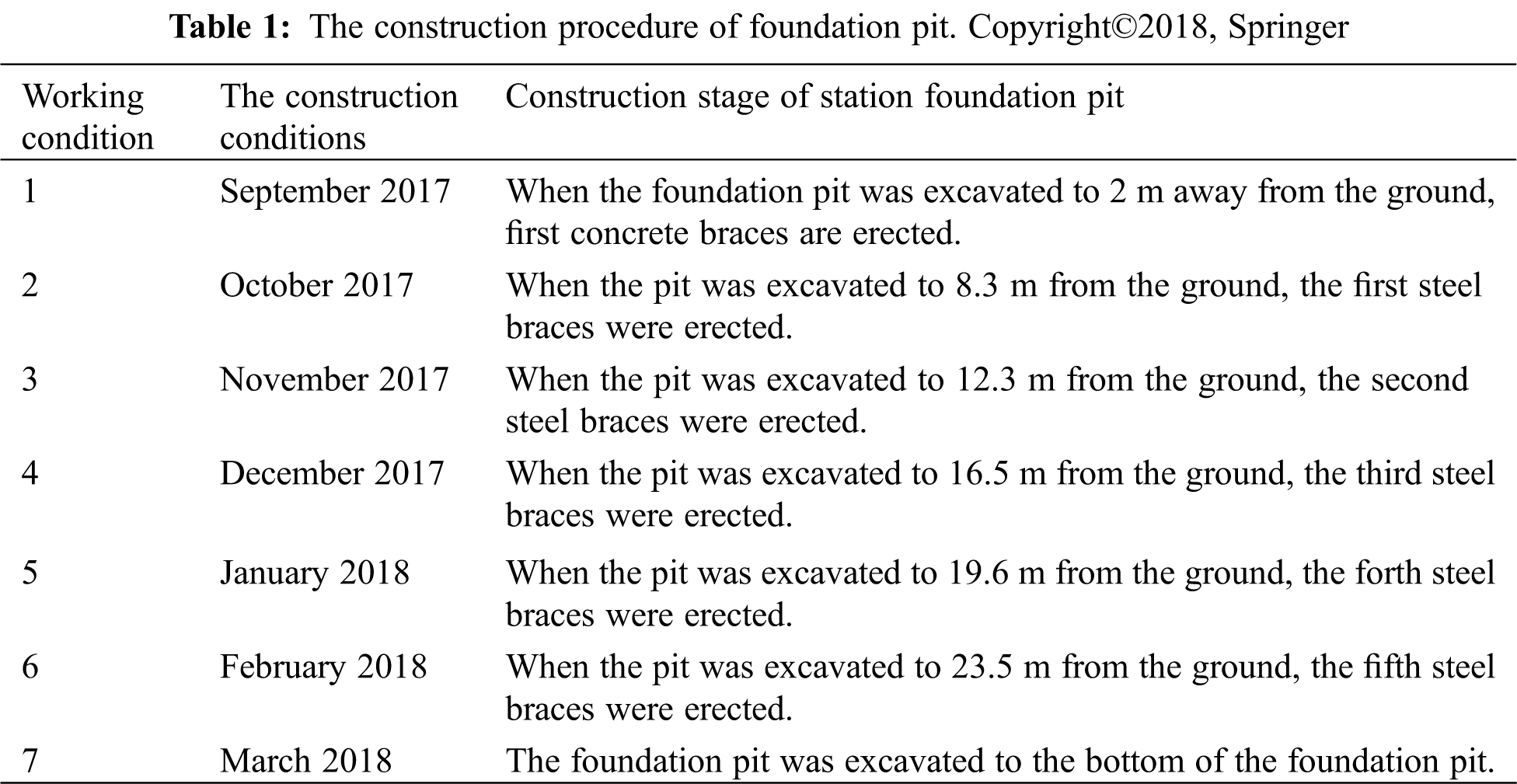
According to the site investigation and specifications, the arrangement of monitoring points and the selection of monitoring devices were shown in Fig. 1. The construction process of the station was shown in Table 1.
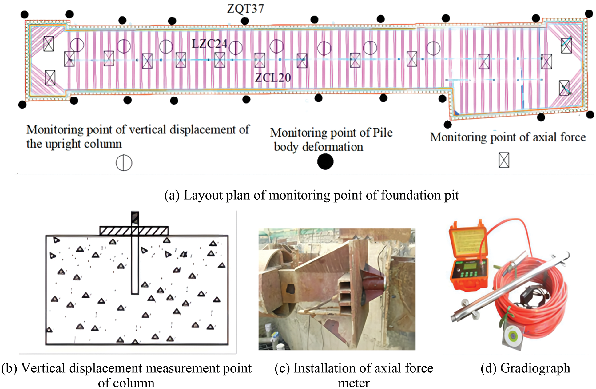
Figure 1: The arrangement of monitoring points and the selection of monitoring devices. Copyright©2018, Springer
The station adopts the common subway station foundation pit support system of enclosure pile + inner support. The enclosure pile diameter is 1.2 m, the pile spacing is 1.4 m, the pile length is 31.5 m, and the excavation depth of the foundation pit is about 25.42~27.07 m. The specific layout plan of the enclosure piles is as follows: 6 steel pipe supports are arranged along the depth direction of the foundation pit, the first is reinforced concrete support, and the horizontal spacing is 9.0 m; the remaining supporting steel pipes are arranged in sequence according to the horizontal spacing of 3.0 m, the second, third, fourth The channel adopts a circular steel pipe with a diameter of 609 mm and a single side wall thickness of 16 mm. The fifth and sixth channels use a round steel pipe with a diameter of 800 mm and a single side wall thickness of 16 mm. The cross-sectional view of the enclosure structure is shown in Fig. 2.
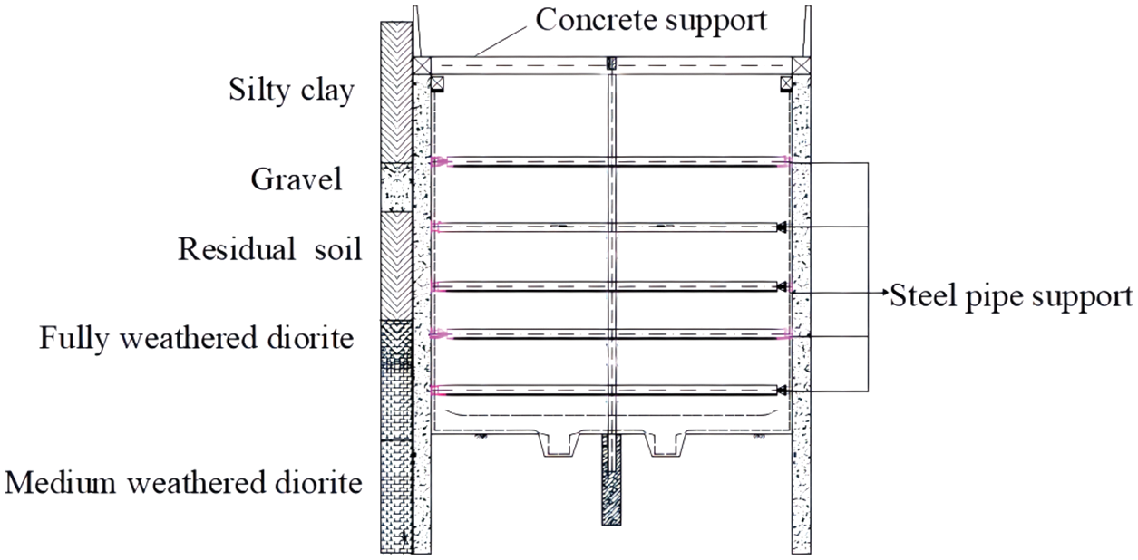
Figure 2: Section layout of retaining structure of station foundation pit. Copyright©2018, Springer
2.4 Field Monitoring Data Analysis of Pile
Fig. 3 depicts the change in horizontal displacement of the ZQT37 measurement point during the foundation pit excavation procedure. The horizontal displacement of the pile body changes relatively smoothly in the early stages of excavation, with the maximum displacement appearing at the top of the pile and the displacement being 1.81 mm; after the foundation pit is excavated to 8.3 meters underground, the change trend of the displacement curve is “forward-inclined,” with the maximum displacement appearing at a position 8 meters away from the pile top and the displacement being 8.2 mm. The maximum displacement appeared at a position 13 m away from the pile top after the foundation pit was excavated to 12.6 m underground, and the displacement was 14.82 mm; after the foundation pit was excavated to 19.6 m underground, the maximum displacement appeared at a position 14 m away from the pile top, and the displacement was 18.78 mm; after excavating 23.3 m underground, the maximum displacement appears at a position 14 m away from the pile top, and the displacement was 18.78 mm. The maximum displacement occurs at a position 14 m away from the pile top after excavating 23.3 m underground, and the displacement is 19.14 mm; after excavating the foundation pit to the base, the maximum displacement occurs at a position 15 m away from the pile top, and the displacement is 23.79 mm; as the excavation progresses, the horizontal displacement curve of the pile body gradually deepens its “forward inclination” and approximates a “parabolic” curve.
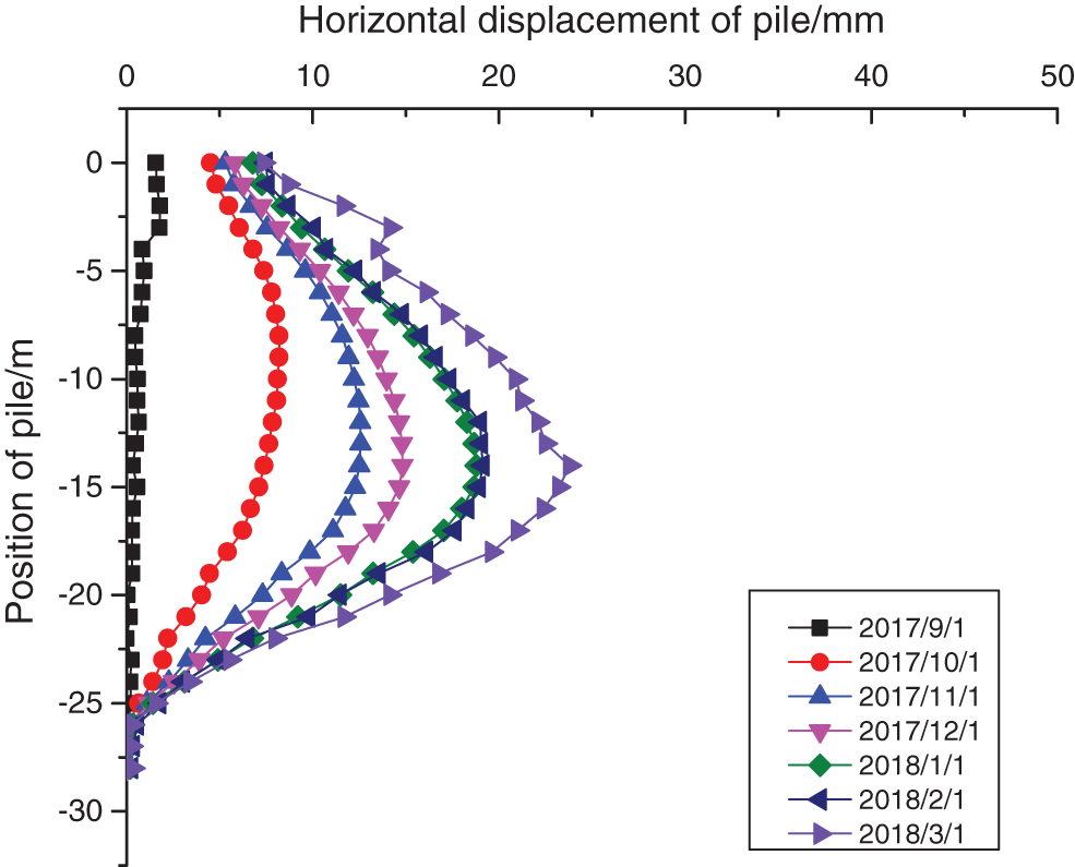
Figure 3: Field monitoring data of ZQT37
Fig. 4 depicts the change in the axial force of the steel support at monitoring points ZCL20-2 to ZCL20-6. From the graph, it can be observed that the axial force of the five monitoring sites increases steadily, however the axial force of measuring point ZCL20-2 decreases. The axial force decreased once and then continuously rose. The reason for this phenomenon is that prestress was applied during the construction of the third steel support; the axial force measured at the ZCL20-4 measuring point has the largest growth rate, and the axial force received is also the largest; the maximum axial force is 1680.3 kN, which is less than its control value of 3544 kN; the ZCL20-6 measuring point has the smallest axial force, and the maximum axial force is 1680.3 kN, which is less than its control value of 3159 kN. The axial forces of the monitoring stations at the bottom of the pit are all fewer than their design values: 1236.5 kN, 1256.3 kN, and 1230.6 kN, respectively.
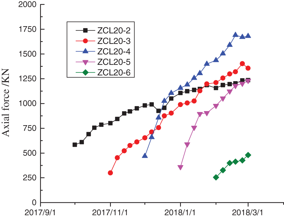
Figure 4: Field monitoring data of ZCL20
In this paper, the monitoring data of the column were selected for analysis. The change curve of monitoring data of LZC24 was shown in Fig. 5. In the process of construction, the column did not settle, but has been in a rising state. Since the beginning of February 2018, the rising rate of the vertical column has slowed down. At this time, the foundation pit was excavated to the bottom, the soil in the lower layer was fully weathered diorite, and the soil was relatively hard. After the excavation of the upper layer, the uplift was small, and the rising rate of the vertical column was slow. The maximum vertical displacement of the column was 11.3 mm, which was less than the control value of 20 mm. The column was stable during construction.
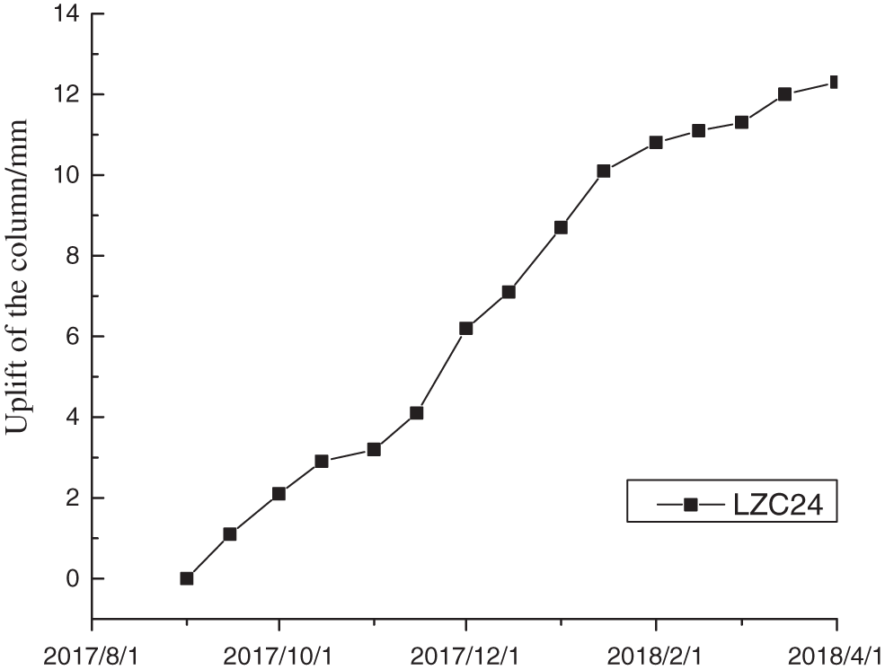
Figure 5: Field monitoring data of LZC24
3 Numerical Simulation and Analysis of Construction Process
3.1 Numerical Calculation Model
The finite difference software FLAC3D was used to simulate the whole process of foundation pit excavation. The width of the standard section of the foundation pit was about 24 m. The length of the foundation pit was about 210 m. The excavation depth was about 25 m. In the process of foundation pit excavation model establishment, the influence range of foundation pit excavation is affected by the foundation pit length-width ratio, so the influence range of foundation pit excavation should be determined according to the actual construction process. According to the three-dimensional numerical calculation and field monitoring results of the existing deep foundation pit, it was shown that the influence of ground settlement caused by excavation was generally not more than 5 times the depth of excavation. The influence range of the ground subsidence was affected by the scale of the foundation pit and the aspect ratio of the foundation pit. Generally, the distance from the cut-off boundary to the bottom of the pit could be 1~3 times that of the final excavation depth. Therefore, the three-dimensional size of the calculation model was 510 × 334 m × 60 m. The calculation model was divided into 84496 nodes and 72105 elements. The constitutive relationship of soil was following the Mohr-coulomb rule. Under the premise of simulation accuracy, the simulation analysis process was simplified as far as possible.
In the process of model calculation, normal constraints are set around the model to limit the displacement of the model, fixed constraints are set at the bottom of the model to limit its deformation, and the top of the model was free surface.
In the natural environment, the soil mass will gradually reach a stable state after deformation due to the dead weight stress. In order to ensure the accuracy of the simulation results, it was necessary to set the gravitational field in the model to keep consistent with the actual situation. The deformation of soil due to dead weight was not caused by the later construction. Therefore, after the initial stress condition was set, the displacement and velocity due to dead weight stress should be set to zero after the model reaches the initial stress balance, and then the foundation pit excavation was calculated.
In the actual construction, the water curtain was set outside the foundation pit, and the foundation pit dewatering was conducted by combining drainage with drainage. The influence of dewatering in the pit on the foundation pit and the external environment was very small, so the influence of dewatering in the pit on the overall environment was not considered.
In this paper, the retaining structure of subway station foundation pit was bored piles. Based on the equivalent stiffness principle, the enclosure structure was modeled as an underground continuous wall structure by isotropic elastic solid element. According to the principle of equivalent stiffness, the thickness of the wall follows the relation of
where,
The wall thickness was 800 mm. The supporting structure adopts beam element, and the Null element was used to realize the excavation of the soil. The three-dimensional calculation model was shown in Fig. 6. The calculation model of the support structure was shown in Fig. 7. The main construction steps were shown in Table 1. The simulation values of retaining piles, supporting axial forces and uplift and subsidence of upright column were analyzed.
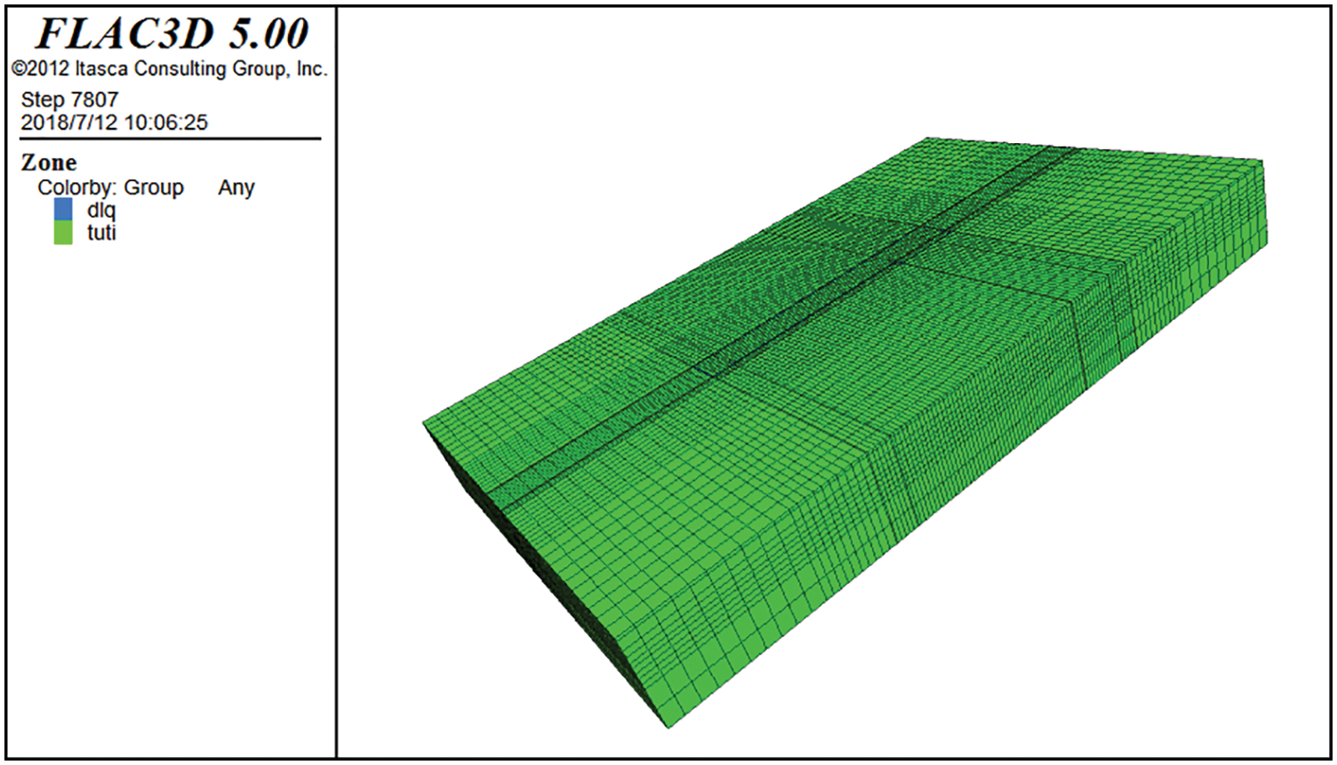
Figure 6: Three-dimensional calculation model
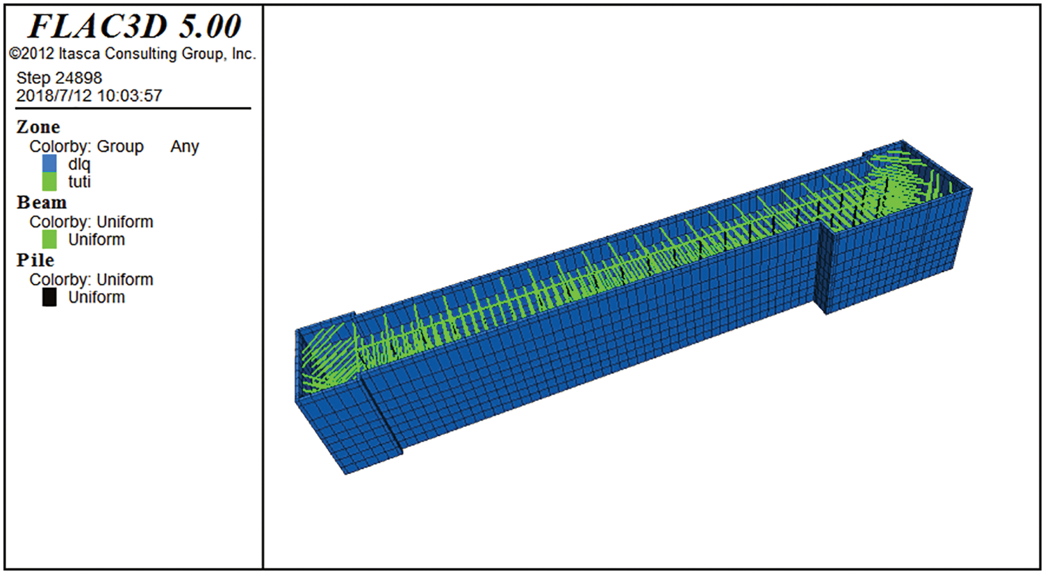
Figure 7: The calculation model of the support structure
According to the field geological exploration data, the calculation parameters of each layer of soil in the model are shown in Table 2.
The horizontal support adopted by this station includes reinforced concrete support and steel support. In the process of numerical simulation, the beam element can be used to simulate the support in the foundation pit. The pile element was selected to simulate the column in the foundation pit. The Support structure model parameters are shown in Table 3.
3.2 Analysis of Simulation Results of Horizontal Displacement of Pile
The horizontal force of the pile body is uneven during excavation of the soil inside the foundation pit, resulting in horizontal displacement of the pile body. For the safe design of the foundation pit, it is of utmost importance to examine the deformation law of the enclosing structure [24–26]. Fig. 8 depicts the horizontal deformation cloud diagram of the envelope structure under various operating conditions, whereas Fig. 9 depicts the horizontal deformation curve of the simulation calculation results of the ZQT37 measuring point corresponding to the field measurement under each operating condition. It can be seen from the figure that, as construction progresses, the maximum position of the horizontal deformation of the enclosure structure gradually moves down from the top of the pile body, and the horizontal deformation gradually increases; the maximum horizontal displacement of working Condition 1 is 1.3 mm; Condition 2, or after the completion of the erection of the first inner support, the maximum displacement occurs at a position approximately 10 m away; and Condition 3, or after the completion of the erection of the second inner support, the maximum displacement occurs At a distance of approximately 15 m from the top of the foundation pit, the displacement is 10.28 mm; in working Condition 4, that is, after the completion of the third inner support erection, the maximum displacement occurs at a distance of approximately 17 m from the top of the foundation pit, and the displacement is 12.89 mm; Condition 5, that is, after the completion of the fourth inner support erection, the maximum displacement occurs at a distance of approximately 17 m from the top of the foundation pit, and the displacement is At a distance of about 17 m from the top of the foundation pit, the displacement is 16.38 mm; in working condition seven, when the construction reaches the bottom of the pit, the displacement is 17.87 mm at a distance of approximately 17 m from the top of the foundation pit.

Figure 8: Horizontal displacement cloud map of the retaining structure
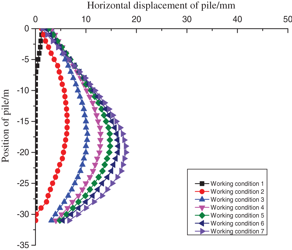
Figure 9: Horizontal displacement curves of ZQT37 monitoring points in different periods
The deformation of the pile body is altered by the installation of the inner support. From the completion of the third inner support installation until the conclusion of construction, the maximum horizontal displacement position remains steady at about 17 m from the top of the foundation pit.
3.3 Analysis of the Simulation Results of Supporting Axial Force
The bracing system was an important part of the structure of the envelope, and the change in bracing axial force was an important indication of how safe the building environment was. Fig. 10 exhibited the supporting axial force cloud map after the foundation pit had been excavated all the way to its bottom. We decided to look at the axial support force that was present in the standard section’s middle region. The data curve of the ZCL20 segment enabling axial force modeling is shown in Fig. 11. As can be seen, the rate of growth of the support’s axial force was stronger during the first phase of the support, but this rate decreased when the lower steel bracing was completed. In spite of this, the axial support force continued to get stronger. During the whole of the excavation process, the axial force that was exerted by the first concrete support was the most it had ever been, reaching a peak value of 4766 kN. It is abundantly clear that the axial force exerted by the steel support was far less than that exerted by the concrete support. After the foundation pit was excavated all the way to the bottom, the axis force of the second supports was the largest, and the maximum axial force was 1444 kilonewtons (kN). The greatest axial force that was applied by a steel support was equivalent to 43% of the value it was designed to handle. 64 percent of the number that was calculated for the concrete support’s maximum axial force was what it really produced. The amounts of supported axial force that were simulated were much lower than the values that were designed for. The findings of the support shaft force modeling showed that the construction site was within a generally safe range, and the installation of the steel support effectively guaranteed that the construction would be carried out in a risk-free manner.
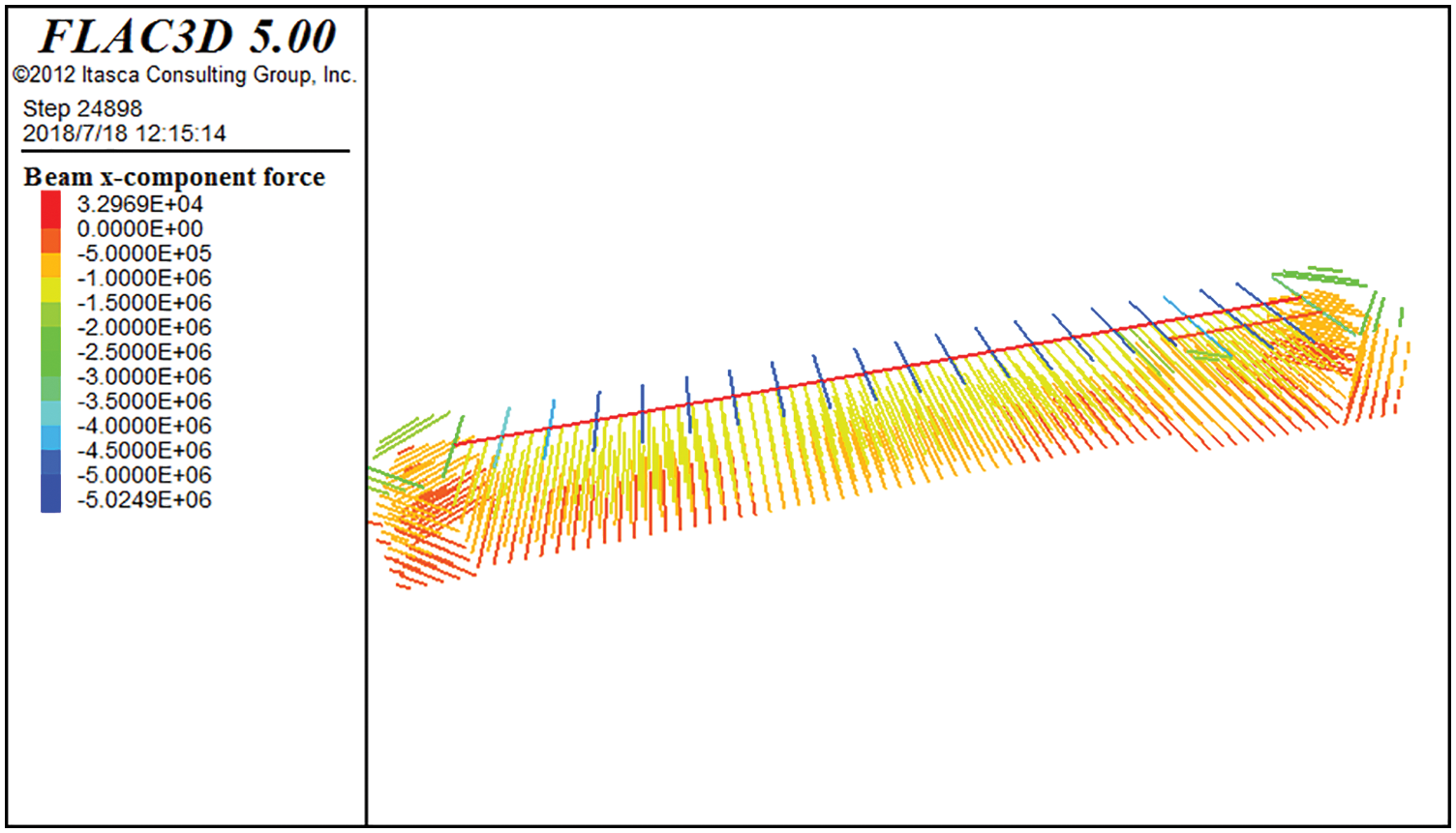
Figure 10: Supporting axial force cloud map
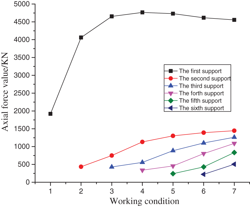
Figure 11: The data curve of ZCL20 section supporting axial force
3.4 Analysis of Upright Column Simulation Results
The unequal displacement of the upright column would result in the differential displacement of the supporting system on the vertical plane and the plane, which would ultimately result in the secondary stress of the supporting axial force [27–30]. If there was a significant settlement between the upright column and the retaining wall or between the upright column and the retaining wall, it would result in eccentric compression or even instability of the supporting system, thereby causing an engineering accident; therefore, the vertical displacement of the column was crucial to the stability of the foundation pit enclosure system. To investigate the change rules, simulated data from the column of the upright standard section were used. Fig. 12 depicts the vertical displacement cloud map of the column after the foundation pit was dug to the bottom of the pit. Fig. 13 depicts the simulation calculation curve of the LZC24 column in the critical building phase. As seen in the illustration, the column was ascending throughout the excavation of the foundation pit. From the installation of the sixth steel support through the excavation of the foundation pit to the bottom of the pit, the column’s uplift growth rate slowed. The highest rise when the foundation pit was dug to its bottom was 10.1 mm. It was less than the 20 mm vigilance threshold, indicating that the foundation pit was largely stable throughout the simulation phase of foundation pit excavation.
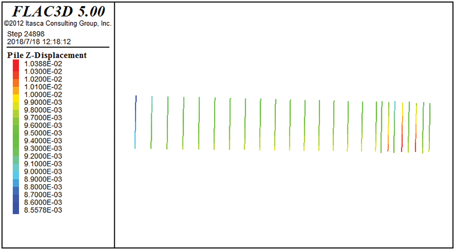
Figure 12: Vertical displacement cloud map of the column

Figure 13: Vertical displacement curve of LZC24 monitoring point
4 Comparison and Analysis of Simulation Results and Monitoring Results
4.1 Comparative Analysis of Horizontal Displacement Simulation and Monitoring Results of Retaining Piles
To demonstrate the accuracy of the simulation findings, the simulation results of the retaining piles under the four primary circumstances were compared with the monitoring data from the field. As seen in Fig. 14, the horizontal displacement of the piles is compared and examined based on modeling and measurement findings. The pile’s displacement is skewed, as shown by the monitoring data collected on-site. When the original reinforced concrete supports were built, the maximum foundation pit displacement was 1.81 mm. As a consequence of the shallow excavation, the displacement from the lower end of the support pile to the foundation pit is much less than that of the higher portion of the support pile, which is compatible with the simulation findings of the support pile. As the depth of excavation grows, the maximum horizontal displacement of the pile steadily decreases. The pile’s deformation curve varies progressively from the top front curve to the arch. From the completion of the fourth assumption of the steel frame until the bottom of the foundation pit excavation, the maximum horizontal displacement does not decrease and tends to remain steady at around 15 m. If the foundation pit is constructed to completion, the horizontal displacement may reach a maximum of 23.79 m. In the simulation, the highest horizontal displacement of the pile was 17.87 mm. The greatest horizontal displacement is around 17 m, the simulated value is similar to the actual value in the field, and a reasonable first conclusion may be taken from the calculation result. The deformation curve of the pile body transitions progressively from an upper straight forward curve to an arcuate shape, with a continuous deformation tendency. The correctness of the numerical simulation findings and the field test results may be independently checked. The findings demonstrate that the numerical model developed in this study can accurately represent the deformation law of the surrounding environment during drilling and may serve as a guide for the design and construction of comparable deep foundation pits.
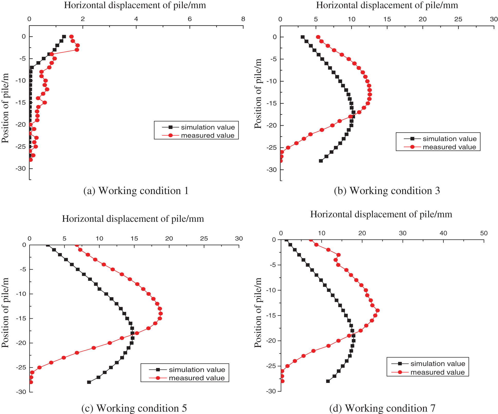
Figure 14: Comparison curves between monitoring values and simulated values of horizontal displacement of retaining piles in key construction stages
4.2 Comparison and Analysis of Support Axial Force Simulation and Monitoring Results
During excavation, the measured and simulated values of six axial supporting forces in the ZCL20 section of the typical standard section were compared. Fig. 15 illustrates the comparison curve between the measured value and the calculated value of the axial force of reinforced concrete supports. Fig. 16 shows the comparison curve between the measured value and the calculated value of the axial force of the steel support. As seen in the picture, the axial force simulation value of the reinforced concrete support was lower than the actual value. The greatest axial force measured on-site for the reinforced concrete support was 5 767.36 kN. The simulation’s highest value was 4855 kN. Since the axial force is again given to the steel bracket during site building, the axial force of the reinforced concrete bracket decreases when the third bracket is installed. Consequently, the variation trend of the measured values of the axial force of the reinforced concrete supports altered under this operating situation, and the measured axial force curve exhibited a decreasing tendency. Later on, however, the axial force fluctuation trend between the observed value and the calculated value steadily converged. During site monitoring, the axial force of steel tube support was much less than that of concrete support, corresponding with modeling findings. The highest value of modeling for the axial force of the steel support was 1444 kN, but the actual maximum value was 1680 kN. Simulated and observed values of support axial force followed a similar development path. With increasing excavation depth, the axial force steadily increased. The axial force design value for the steel support was 3284 kN. When the foundation pit was completely dug, the measured and simulated values were much less than the design values. It was shown that the supporting system was generally stable throughout excavation, although the steel support design was overly cautious. By comparing the measured value to the simulated value, it was determined that the model, parameter selection, and calculation technique for the support system were appropriate.
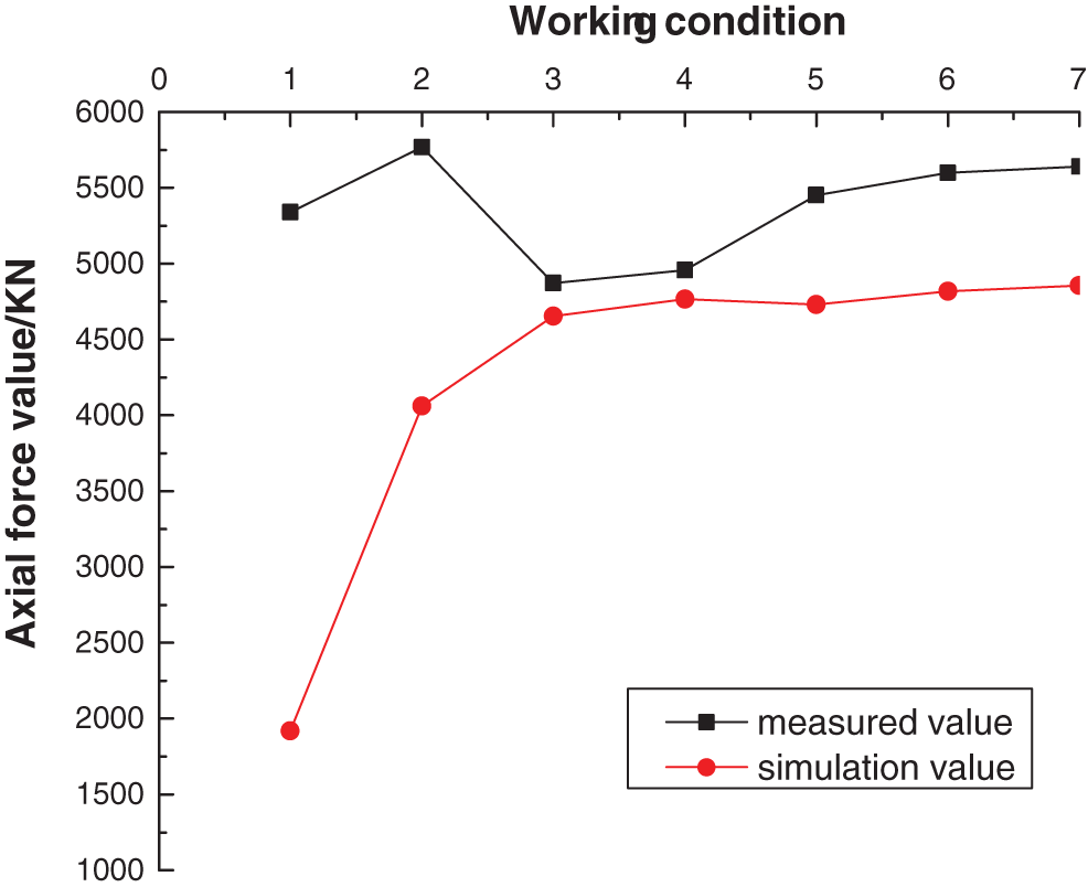
Figure 15: The comparison curve between the measured value and the simulated value of the axial force of reinforced concrete supports
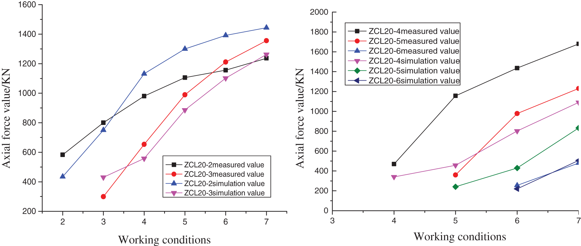
Figure 16: The comparison curve between the measured value and the simulated value of the axial force of the steel support
4.3 Comparison and Analysis of Uplift and Subsidence of Upright Column Simulation and Monitoring Results
Fig. 17 shows a comparison of measured and simulated vertical displacement values for the LZC24 location. As seen in the image, the column had been ascending throughout foundation pit excavation. When the foundation pit was dug to its bottom, the greatest distance of the observed vertical column rise is 12.3 mm, whereas the maximum distance of the simulated vertical column rise is 10.1 mm. The simulated values corresponded to the actual values. From the change in the column’s uplift, it was determined that during the excavation of the foundation pit, uplift at the bottom of the pit and vertical load caused the column’s vertical displacement. The excavation of the foundation pit resulted in the unloading of dirt at the pit’s base, resulting in the uplift deformation of the soil layer. The elevation of the foundation pit’s bottom led the column pile to float, while the vertical load forced the column to sink. As the foundation pit was dug, the stress release at the bottom of the pit and the rebound of the soil in the pit led the column to rise owing to the upward friction of the pile. It was shown that the upward friction force dominated the vertical displacement of the column, resulting in an upward trending column pile. During foundation pit excavation, the vertical load of the column’s top might be raised to limit the column’s uplift and preserve the stability of the supporting system.

Figure 17: The comparison between measured and simulated values of vertical displacement of LZC24 point
The retaining structure resists the pressure of earth outside the pit to create a safe environment for building within the pit. In construction, the appropriate embedded depth of retaining piles must be determined based on the excavation depth of the foundation pit. The embedded depth of retaining piles has a significant impact on the foundation pit’s stability. When the embedded depth of the retaining pile is insufficient, the retaining structure is susceptible to kick-type collapse during the building of the foundation pit. If the embedding depth of the retaining pile is too great, the amount of trash and the total cost of the project will be excessive.
In this part, FLAC3D software is used to model retaining structures with varying embedded depths; the embedded depths of retaining piles are sequentially set to 3 m, 5 m, 7 m, 9 m, and 11 m. By analyzing the horizontal displacement of retaining piles, the link between the foundation pit’s stability and the embedded depth of retaining piles is evaluated.
According to the building specifications, the foundation pit excavation depth is 25 meters. Fig. 18 depicts the horizontal deformation cloud map of the retaining pile at various depths after excavation to the bottom of the pit, while Fig. 19 depicts the deformation curve of the retaining pile in the center of the standard section.
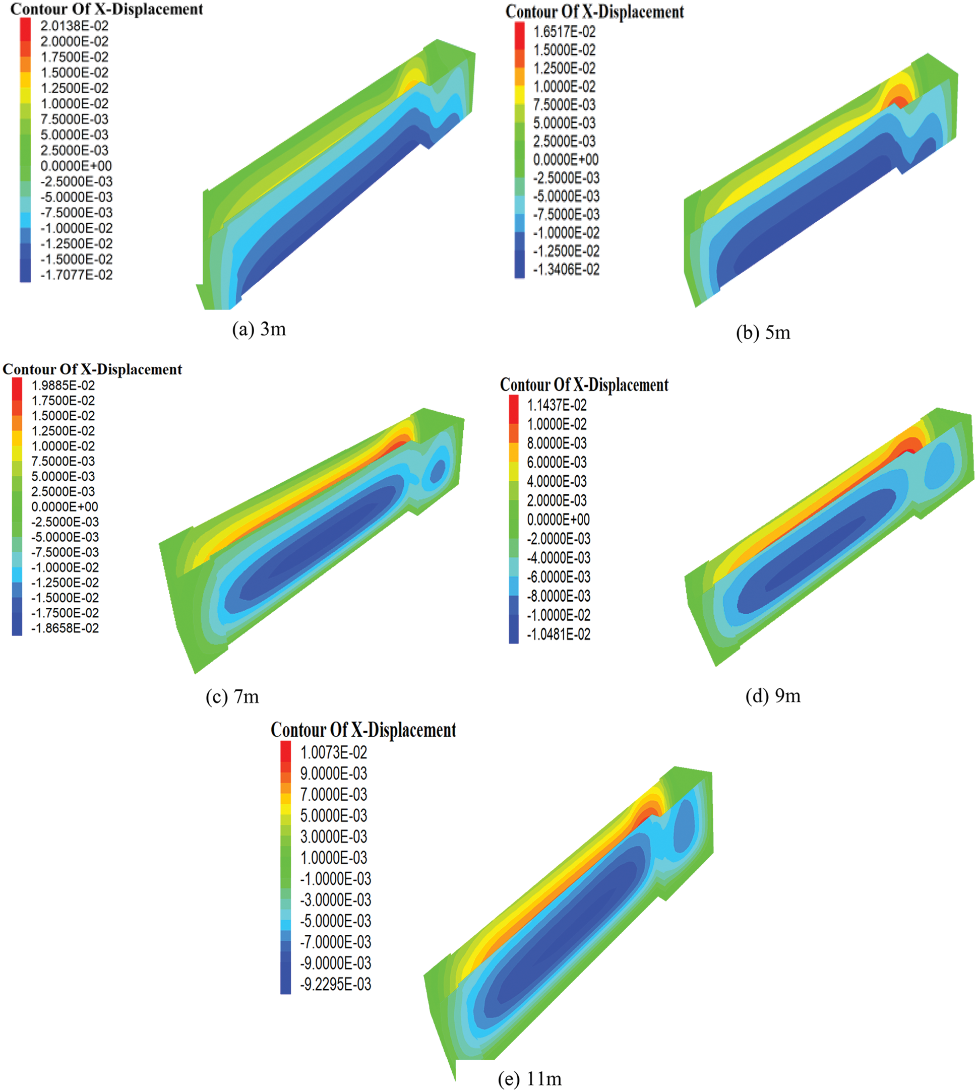
Figure 18: Horizontal deformation cloud map of different retaining structures
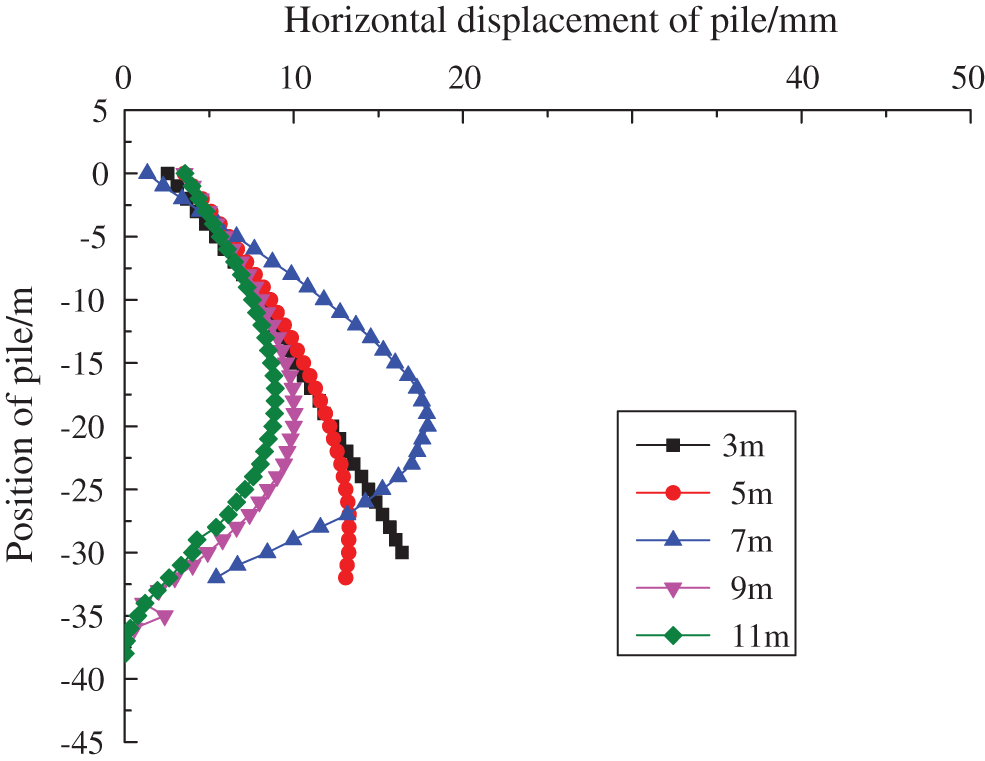
Figure 19: Deformation curve of envelope structure with different depth of soil
As shown in Fig. 18, when the embedment depth is 3 m, the deformation of the retaining pile is substantial, with a maximum deformation of 20.14 mm, with the greatest deformation occurring near the base. When the depth is 5 meters, the maximum deformation of the retaining pile is 16.52 mm, and the greatest deformation remains at the pile’s base. When the excavation depth is 3 m or 5 m, the deformation curves of the retaining pile are equivalent. Although the deformation is less than the control value, the largest deformation is situated near the bottom of the pile, which makes it easier for the kicking phenomena of the retaining pile to occur during construction, leading to the instability of the foundation pit.
When the embedded depth is 7 m, 9 m, and 11 m, the maximum horizontal displacement is 17.87 mm, 11.43 mm, and 10.07 mm, respectively (see Fig. 19). Increasing the embedded depth lowers the deformation of the retaining pile by a substantial amount. When the buried depth is 7 m, 9 m, and 11 m, respectively, the location of the maximum deformation of the retaining pile has clearly shifted higher compared to when the immersed depth was 3 m and 5 m. Increasing the embedded depth may thereby avoid the kicking phenomena of the retention pile from causing the foundation pit to become unstable. When the embedding depth is increased from 7 m to 9 m, the maximum deformation falls by 6.44 mm, or about 36%. When the embedded depth increases from 9 m to 11 m, the maximum deformation lowers by 1.36 millimeters, or about 11.9%. Although the embedded depth rises by 2 m, the impact on deformation reduction is unclear. It demonstrates that the impact is optimal when the embedded depth is between 7 and 9 m, or when the embedded ratio (ratio of embedded length to foundation pit excavation depth) is between 28 and 32 percent. An excessive increase in the embedded depth of the retaining pile may minimize deformation, but the benefit is minimal, resulting in a waste of resources.
1) The maximum horizontal displacement of the retention pile was proportional to the excavation depth and the installation of the support. During the first phase of excavation, the retaining pile’s greatest horizontal displacement occurred near its apex. The maximum horizontal displacement position of the pile body continuously decreased as the excavation depth of the foundation pit and the installation of each support progressed. At 17~19 m, the greatest horizontal displacement position of the pile ceased to change. The pile’s deformation curve altered, and the deformation of the pile exhibited a large belly shape, with the overall curve being “bow-shaped.” The simulation findings are comparable to field monitoring data, and the simulation process’s correctness has been validated.
2) By comparing the measured and predicted findings, it was determined that the design of the steel support was too cautious. Using this numerical technique, further optimization of the steel support supporting system proved problematic due to the construction conditions on the job site.
3) The column has been ascending throughout the excavation of the foundation pit. According to the comparison and analysis of site construction and numerical simulation, the vertical load of the column might be raised during foundation pit excavation to maintain the stability of the support system.
4) During the real building process, the foundation pit excavation would affect the soil and the enclosing structure, and the soil and enclosing structure’s characteristics will change, which was not the case in the actual circumstance. This issue will be examined later. Even though the numerical simulation process is as close as possible to the actual project, the impact of the foundation pit construction process on the surrounding environment is not taken into account in this paper, so there is a slight discrepancy between the numerical simulation results and the actual monitoring results.
5) In the simulation of foundation pit excavation, the erection of steel support has a significant impact on the deformation of the foundation pit retaining pile and the surrounding soil; therefore, the erection time and position of steel support must be consistent with the actual construction process.
Funding Statement: This work was supported by the National Natural Science Foundation of China (51774199).
Conflicts of Interest: The authors declare that they have no conflicts of interest to report regarding the present study.
References
1. Bantayehu, U. U., Guo, Y. (2020). Deep foundation pit excavations adjacent to disconnected piled rafts: A review on risk control practice. Open Journal of Civil Engineering, 10(3), 270–300. DOI 10.4236/ojce.2020.103023. [Google Scholar] [CrossRef]
2. Estanislao, P., Anna, J. (2021). Groundwater-related aspects during the development of deep excavations below the water table: A short review. Underground Space, 6(1), 35–45. DOI 10.1016/j.undsp.2019.10.002. [Google Scholar] [CrossRef]
3. Bian, X., Hu, H. (2021). Protective effect of partition excavations of a large-deep foundation pit on adjacent tunnels in soft soils: A case study. Bulletin of Engineering Geology and the Environment, 80(7), 5693–5707. DOI 10.1007/s10064-021-02256-9. [Google Scholar] [CrossRef]
4. Yu, C. (2019). Study on the influence of deep foundation pit excavation on existing structures around. DEStech Transactions on Engineering and Technology Research, S1, 478–482. DOI 10.12783/dtetr/icaen201/29058. [Google Scholar] [CrossRef]
5. Ryan, M., Mary, M., B. Stephen, R. (2020). Identifying and mapping potentially adverse discontinuities in underground excavations using thermal and multispectral UAV imagery. Engineering Geology, 266(5), 105470. DOI 10.1016/j.enggeo.2019.105470. [Google Scholar] [CrossRef]
6. Waseem, K., Carole, L., Feargal, B. (2021). Characterisation of pitting corrosion for inner section of offshore wind foundation using laser scanning. Ocean Engineering, 230(6), 109079. DOI 10.1016/j.oceaneng.2021.109079. [Google Scholar] [CrossRef]
7. Valipour, A. (2019). A swara-copras approach to the allocation of risk in water and sewerage public-private partnership projects in malaysia. International Journal of Strategic Property Management, 23(4), 269–283. DOI 10.3846/ijspm.2019.8066. [Google Scholar] [CrossRef]
8. Xie, P. (2017). Monitoring analysis of deep foundation pit on qingdao metro dug station. Railway Investigation and Surveying, 43(2), 25–28. DOI 10.19630/j.cnki.tdkc.2017.02.007. [Google Scholar] [CrossRef]
9. Elbaz, K., Shen, S. L., Tan, Y., Cheng, W. C. (2018). Investigation into performance of deep excavation in sand covered karst: A case report. Soils and Foundations, 58(4), 1042–1058. DOI 10.1016/j.sandf.2018.03.012. [Google Scholar] [CrossRef]
10. Tian, W., Meng, J., Zhong, X. J., Tan, X. (2021). Intelligent early warning system for construction safety of excavations adjacent to existing metro tunnels. Advances in Civil Engineering, 2021(6), 8833473. DOI 10.1155/2021/8833473. [Google Scholar] [CrossRef]
11. Gotman, A. L., Gotman, Y. A. (2019). Numerical analysis of the shorings of deep foundation pits with regard for the soil solidification. Soil Mechanics and Foundation Engineering, 56(4), 225–231. DOI 10.1007/s11204-019-09595-6. [Google Scholar] [CrossRef]
12. Li, M. G., Wang, J. H., Chen, J. J., Zhang, Z. J. (2017). Responses of a newly built metro line connected to deep excavations in soft clay. Journal of Performance of Constructed Faceilities, 31(6), 232–245. DOI 10.1061/(ASCE)CF.1943-5509.0001091. [Google Scholar] [CrossRef]
13. Yang, J. H., Kong, D. Y. (2020). Deformation of deep and large foundation pit in soft soil of Fuzhou Subway. Arabian Journal of Geosciences, 13(2), 435–448. DOI 10.1007/s12517-019-4918-7. [Google Scholar] [CrossRef]
14. Xiao, H. J., Zhou, S. H., Sun, Y. Y. (2019). Wall deflection and ground surface settlement due to excavation width and foundation pit classification. KSCE Journal of Civil Engineering, 23(4), 1537–1547. DOI 10.1007/s12205-019-1712-8. [Google Scholar] [CrossRef]
15. Ding, Z., Jin, J. K., Han, T. C. (2018). Analysis of the zoning excavation monitoring data of a narrow and deep foundation pit in a soft soil area. Journal of Geophysics and Engineering, 15(4), 1231–1241. DOI 10.1088/1742-2140/aaadd2. [Google Scholar] [CrossRef]
16. Cui, X. Y., Ye, M. G., Zhuang, Y. (2018). Performance of a foundation pit supported by bored piles and steel struts: A case study. Soils and Foundations, 58(4), 1016–1027. DOI 10.1016/j.sandf.2018.05.004. [Google Scholar] [CrossRef]
17. Zeng, F. Y., Zhang, Z. J., Wang, J. H., Li, M. G. (2018). Observed performance of two adjacent and concurrently excavated deep foundation pits in soft clay. Journal of Performance of Constructed Facilities, 32(4), 1046–1057. DOI 10.1061/(ASCE)CF.1943-5509.0001184. [Google Scholar] [CrossRef]
18. Stahlhut, O., Borchert, K. M., Voigt, R. E. (2018). Design and execution of a trough excavation pit in the Hamburg city center considering complex structural conditions. Bautechnik, 95(1), 62–71. DOI 10.1002/bate.201700106. [Google Scholar] [CrossRef]
19. Moormarm, C. (2004). Analysis of wall and ground movements due to deep excavations in soft soil based on new worldwide database. Soils and Foundations, 44(1), 87–98. DOI 10.3208/sandf.44.87. [Google Scholar] [CrossRef]
20. Oztoprak, S., Cinicioglu, S. F., Oztorun, N. K. (2020). Impact of neighbouring deep excavation on high-rise sun plaza building and its surrounding. Engineering Failure Analysis, 111(10), 104495. DOI 10.1016/j.engfailanal.2020.104495. [Google Scholar] [CrossRef]
21. Qiu, Q. Y. (2018). Construction monitoring of deep foundation pit of comprehensive station area sheared by subway station and high-speed railway station and the analysis. Drilling Engineering, 45(6), 52–56. [Google Scholar]
22. Liu, J., Shi, C., Lei, M., Cao, C., Lin, Y. (2020). Improved analytical method for evaluating the responses of a shield tunnel to adjacent excavations and its application. Tunnelling and Underground Space Technology, 98, 103339. DOI 10.1016/j.tust.2020.103339. [Google Scholar] [CrossRef]
23. Bantayehu, U. U., Guo, Y. (2019). Research progress on the influence of deep foundation pit excavation on adjacent pile foundation. Ninth International Conference on Advances in Civil, Structural and Mechanical Engineering. Italy, Rome. DOI 10.15224/978-1-63248-182-5-03. [Google Scholar] [CrossRef]
24. Maddah, A., Soroush, A., Shafipour, R. (2021). A new concept for interpretation of building-excavation interaction in 3D conditions. Tunnelling and Underground Space Technology, 109(3), 103757. DOI 10.1016/j.tust.2020.103757. [Google Scholar] [CrossRef]
25. Wang, Z. C., Wang, C. (2019). Analysis of deep foundation pit construction monitoring in a metro station in jinan city. Geotechnical and Geological Engineering, 33(4), 813–822. DOI 10.1007/s10706-018-0651-3. [Google Scholar] [CrossRef]
26. Khosravi, M., Khosravi, M. H., Najafabadi, S. H. G. (2021). Determining the portion of dewatering-induced settlement in excavation pit projects. International Journal of Geotechnical Engineering, 15(5), 563–573. DOI 10.1080/19386362.2018.1467858. [Google Scholar] [CrossRef]
27. Yu, Z. T., Wang, H. Y., Wang, W., Ling, D. S., Zhang, X. D. et al. (2021). Experimental and numerical investigation on the effects of foundation pit excavation on adjacent tunnels in soft soil. Mathematical Problems in Engineering, 2021(3), 5587857. DOI 10.1155/2021/5587857. [Google Scholar] [CrossRef]
28. Zhang, X., Wei, G., Lin, X., Xia, C., Wei, X. (2021). Transverse force analysis of adjacent shield tunnel caused by foundation pit excavation considering deformation of retaining structures. Symmetry, 13(8), 1478. DOI 10.3390/sym13081478. [Google Scholar] [CrossRef]
29. Ye, S., Zhao, Z. (2020). Deformation analysis and safety assessment of existing metro tunnels affected by excavation of a foundation pit. Underground Space, 6(4), 421–431. DOI 10.1016/j.undsp.2020.06.002. [Google Scholar] [CrossRef]
30. Gao, X., Tian, W. P., Zhang, Z. (2020). Analysis of deformation characteristics of foundation-pit excavation and circular wall. Sustainability, 12(8), 3164. DOI 10.3390/su12083164. [Google Scholar] [CrossRef]
Cite This Article
 Copyright © 2022 The Author(s). Published by Tech Science Press.
This work is licensed under a Creative Commons Attribution 4.0 International License , which permits unrestricted use, distribution, and reproduction in any medium, provided the original work is properly cited.
 Downloads
 Citation Tools