| Structural Durability & Health Monitoring |
DOI: 10.32604/sdhm.2022.015732
REVIEW
Review Article on Condition Assessment of Structures Using Electro-Mechanical Impedance Technique
Department of Civil Engineering, MNNIT Allahabad, Prayagraj, 211004, India
*Corresponding Author: Krishna Kumar Maurya. Email: krish01990@gmail.com
Received: 09 January 2021; Accepted: 20 May 2021
Abstract: Structural health monitoring (SHM) is a process for determination of presence, location, severity of damages and remaining life of the infrastructures. SHM is widely applied in aerospace, mechanical and civil engineering systems to assess the conditions of structures to improve the operation, safety, serviceability and reliability, respectively. There are various SHM techniques for monitoring the health of structures such as global response based and local techniques. Damages occur in the structures due to its inability to withstand intended design loadings, physical environment and chemical environment. Therefore, damage identification is necessary to improve the durability of the structures for protection against catastrophic failure. The research paper is focused on electro-mechanical impedance (EMI) technique which is one of the techniques based on smart materials. The smart materials are utilized for monitoring the health of the structures. These are used for damage determination and its quantification for the interrogated structures. Variation in admittance or impedance signature shows the existence of damage in the structures. Furthermore, the different statistical methods viz., root mean square deviation (RMSD), mean absolute percentage deviation (MAPD), covariance (Cov), and correlation coefficient (CC) are used for the quantification of damage. Smart material such as piezoelectric materials, its properties and applications are also considered. In this paper, the implementation of EMI technique based on different recent advances in smart materials and their appropriateness have been described. Subsequently, the reviewed investigations are significant for the monitoring of real-life infrastructures. The presented paper is the compact state-of-the-art for EMI technique which is used for SHM. This examination will be valuable to infrastructural health monitoring and engineering applications in respect to innovative research directions.
Keywords: Structural health monitoring; condition assessment; EMI technique; PZT patches; damages
Construction of the civil infrastructures is continuously going on not only in India but also in other parts of the world from decades. Now, aging of the infrastructures is facing a maintenance problem for which engineers are not logistically prepared. It has been observed that many such recent incidents, like the abrupt failure of bridges, collapse of aircraft and shuttles are causing loss of prosperity and life. Therefore, to protect against the catastrophic failure, the concept of health monitoring of infrastructures was developed. Furthermore, there is need to monitor the health of infrastructures in various aspects viz., studying the behavior of structures, the economy of the nation, online monitoring of structures, the safety of occupants, proper functioning of structures and determining the actual residual strength of structures [1–3], etc.
Structural health monitoring (SHM) is one of the best significant industrialised technique for determining the structural integrity. The purpose of SHM techniques is not essentially to recognize structural failures, then moreover to support an early indication of physical damage. Considering the early indication of damage developed by an SHM framework the corrective measures may be started since the structural damage leads to collapse. The advancement in SHM techniques provides a mode to advance the safety, reliability, reducing operation cost and reducing maintenance cost of structures. The SHM techniques cover the four-levels of damages viz., to establish that damage has appeared or to recognize damage or presence of damage, to identify damage and to determine its location, to identify, trace and to investigate its severity, and to recognize, trace and quantify damage and to find out residual valuable life of structures for proper monitoring the health of structures. In the present scenario, SHM techniques are used for monitoring the civil infrastructures viz., bridge, dams, water lined structures, buildings, offshore platforms, pipelines and historical monuments [1–6].
Further, SHM techniques can be categorized as global response based techniques and local damage identification techniques to investigate the health conditions of engineering structures. The global response based technique includes global dynamic and global static response based techniques, correspondingly. Global static response technique depends on the displacement parameter [7]. In static response technique, displacement is measured corresponding to force applied to the structures. Later, strain parameter was considered for SHM in global static technique in 1996, which have a higher degree of precision than the displacement parameter [3]. The global static techniques require massive machinery for a small amount of displacement and there are a lot of computational problems. Therefore, in the present scenario application of such technique is too tedious and costly for the real-life structures [8].
Subsequently, the global dynamic response based technique is related towards low-frequency stimulus either may be impulsive or harmonic and corresponding vibration responses viz., displacement, velocity, and acceleration are measured. Further, the change in stiffness, change in flexibility and stored energy are also considered in global dynamic technique to investigate the existence of damage, position and severity of damage. Any change in the baseline data shows the existence of damage in the structures [3,9,10]. The global dynamic technique has several limitations in real-life applications, these limitation are as follows: the technique is not much sensitive for incipient damage and generally relies on first few mode shapes only, the total cost of structure is much more because of expensive hardware and sensors requirement like accelerometer, inertial shaker and laser velocity meter, besides the electrical and electromagnetic noise the interference produced by ambient mechanical noise in the measurement system, and functionality of the techniques fails in several damage situations [11]. Thus, the global dynamic response based technique is insignificant in numerous situations [3,5,10].
Now, local SHM technique are another category of damage detection technique, which includes some of the methods such as X-ray diffraction, magnetic field, eddy-current test, dye penetrant inspection, acoustic emission, ultrasonic pulse velocity test, impact-echo test, and rebound hammer test, etc. The local techniques have several limitations like the machinery system necessity to be moved manually for recording data around the host structure, removal of finishes or covers required before starting the test on the structures and not suitable for structures which is under service condition such as in the cases of bridge when it is in function and aircraft during flight etc. The instruments like X-ray and computer topography in the local technique are limited to very high-performance elements only, because of high range machinery cost [1].
Further, the emergence of smart material and smart structures from past few years are developed the innovative promises intended for SHM and NDT. Because of the smartness of materials, any change in the environment exhibit higher sensitivity [2,12]. The EMI technique depends on smart materials concept and presently applied in many engineering fields. The theoretical development of the use of impedance investigation for SHM was primarily produced by Liang et al. [13] and consecutively established by Bhalla at al. [14–27]. The piezoelectric-ceramic lead zirconate titanate (PZT) patches are surface glued or embedded in the interrogated structures using epoxy adhesive and electrically excited by impedance analyzer/LCR (inductance L, capacitance C and resistance R) meter in EMI technique [2,3,6,28–32].
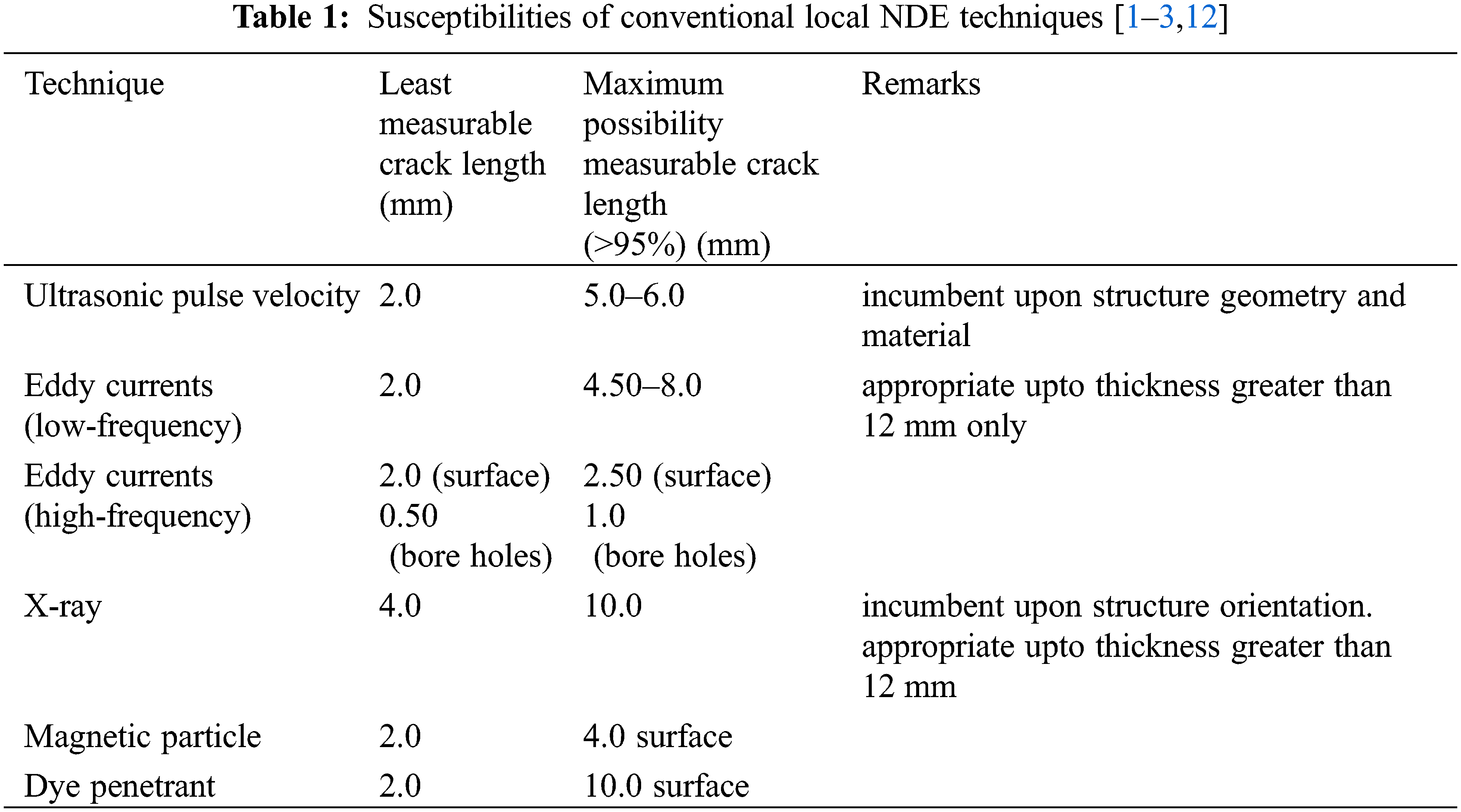
Moreover, electro-mechanical admittance signature is measured to find out existence, position and severity of damages. These signatures have two components such as conductance signature (real part) and susceptance signature (imaginary part), respectively. The conductance signature demonstrates a sharp peak refers to structural modes of vibration. However, in the case of the susceptance signature, the structural modes of interaction are very weak. Therefore, the real part of admittance signature ‘conductance’ is considered for damage identification instead of imaginary part ‘susceptance’ [6,33]. Any deviation in admittance signature from healthy state condition shows the presence of damage in the infrastructure. To predict damage in advanced structures, EMI technique is the most significant method in such scenarios [4]. Table 1 shows the sensitivities of standard local NDE techniques. The review paper is focused on determination the presence of damages and its location, quantification of damage using the EMI technique, which is helpful the monitoring of real-life structures and give new research directions to industrial development. In the next section damage, types of damage and causes of damage have been covered.
2 Damages in Concrete Structures
If the loads are applied on the structural system, damages are developed. Any variation in the physical properties of the material, boundary conditions, connections or dimensional parameters of the structures is termed as damage. If the damages occur in the structural system, performance is adversely affected [3,12]. Generally, the categories of damage/flaws in concrete infrastructures are fire damage, damage due to cracking, corrosion damage, concrete spalling, and freeze and thaw damage, respectively [34]. Damage in concrete structures due to fire is micro-cracking and cracking in the surface zone, alteration of phases in aggregate and dehydration of cement paste, respectively. The damages can be classified based on its severity such as incipient, moderate and severe damages. The changes in the temperature develop severe cracks near reinforcement and micro-cracks along the aggregate surface because of the difference between linear expansion of cement paste and aggregate [35].
Further, the deterioration mechanism in concrete infrastructures is due to cracks growth, therefore sometimes cracking is the cause of damage in the structures [36]. Cracking in concrete structures are developed due to several reasons such as alkali-silica reaction, freeze and thaw, faulty design, settlement in structures, carbonation, sulfate attack and chloride attack, respectively [34,37]. Types of cracks that developed in the structure are shown in Fig. 1. The cracks develop due to physical changes in concrete such as aggregate shrinkage, drying shrinkage, crazing, restrained shrinkage and freeze-thaw, respectively. Types of cracks resulting from chemical changes are the alkali-silica reaction, sulfate attack, corrosion of reinforcement and carbonation, respectively. The thermal cracks are viz., seasonal temperature changes and thermal contraction and structural cracks are such as overload, improper design and excessive movement [34].
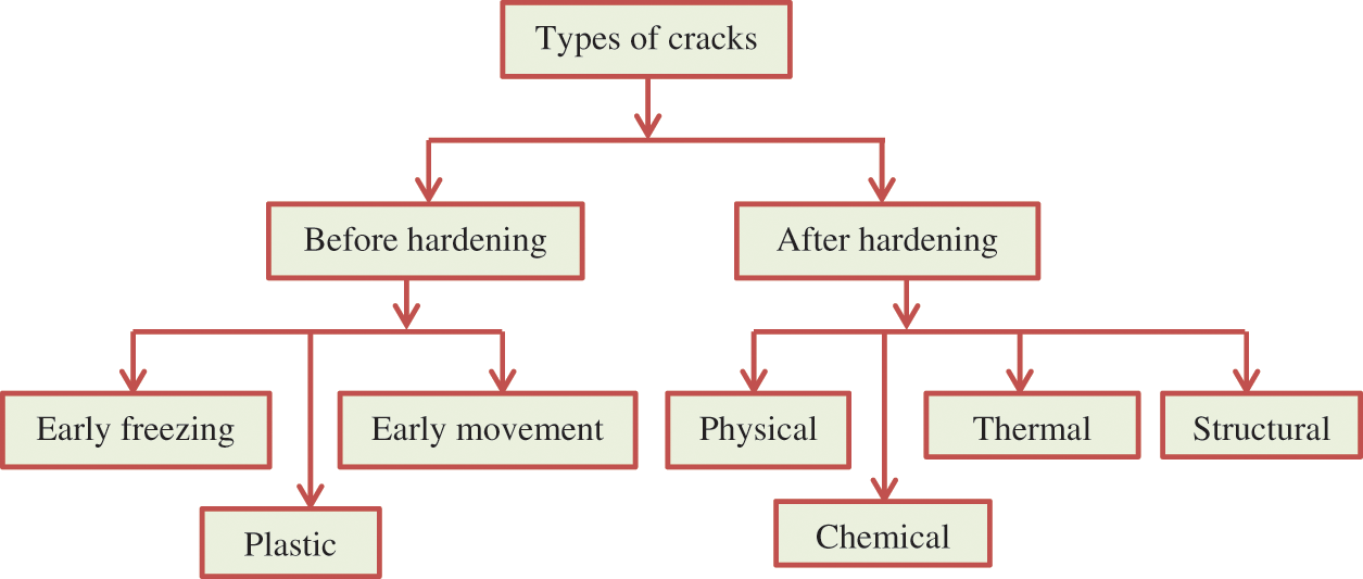
Figure 1: Flow chart of types of cracks [34]
Furthermore, the corrosion of reinforcement is not due to loss of steel but the formation of oxide film on steel which is three to six times more in volume of steel causes damage to the concrete [38]. The entrance of chloride element in concrete structures is main reason of steel rebar corrosion [39]. The separation of concrete cover from host structure is termed as spalling of concrete, which occurs due to the corrosion of reinforcement, causes damage to the structure. Fig. 2 shows that formation of cracking in corresponding concrete such as initiation of corrosion, whereas if corrosion is high then spalling and delamination occurs, which results in damage to concrete [36]. Delamination is defined as the separation of concrete cover parallel to the reinforcement. Freeze and thaw damage is due to the water entrapped in the pores of moist concrete; freezes and expands results high internal pressure can disrupt the concrete surface [37].
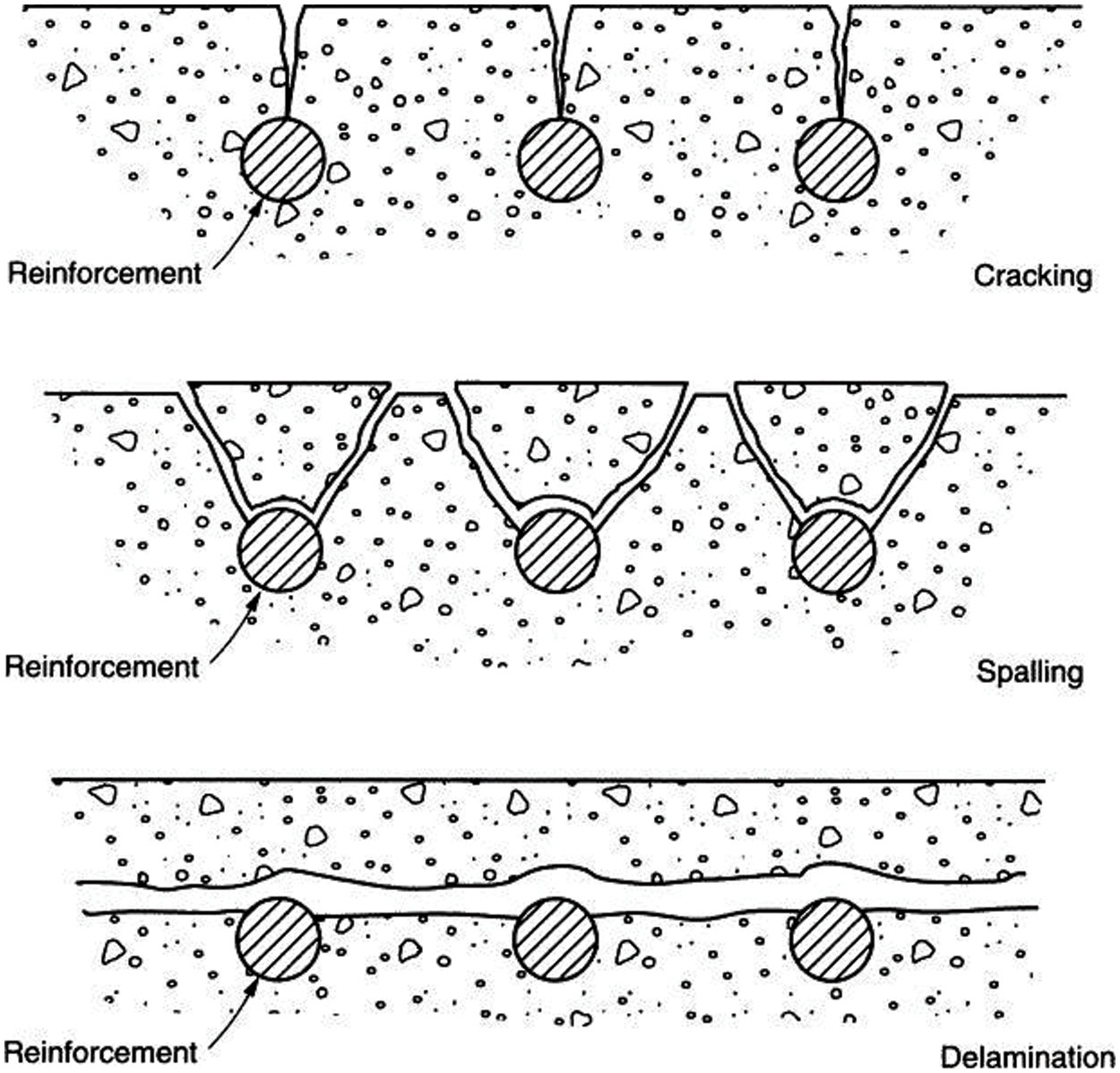
Figure 2: Damage in concrete due to corrosion of reinforcement [37]
Hence, the formation of damage results collapse of the structures. Therefore, monitoring the health is to be done to protect the structures from failure/collapse. The severity of damage must be determined at regular interval so that rate of increase of damage severity can be identified. The EMI technique was used for identification of damage in structural system. In this section, causes and classification were discussed. In the next section, the detailed description of EMI technique and related recent literatures has been discussed.
EMI technique works on high frequency range 30 kHz to 400 kHz. However, in global dynamic response techniques the frequency working range is less than 100 Hz. Thus, the EMI technique is highly sensitive to determine the incipient damage, whereas the global dynamic technique is highly sensitive for determination of severe damage. In EMI technique, PZT sensors are attached on the surface of interrogated specimen using epoxy adhesive. Moreover, PZT sensors are electrically excited using impedance analyzer or LCR meter. Electro-mechanical admittance signature is extracted, which consists of real part (conductance) and imaginary part (susceptance). The plot of admittance signature with frequency gives unique signature of coupled system. The obtained electro-mechanical admittance signature is equated with baseline healthy state signature of the structure. Any deviation in admittance signature shows existence of damage in infrastructures [2–4,12,28,29,40–43].
In 1880, Curie introduced the theory of piezo-electricity. There are certain specific materials like LiNbO3 (Lithium Niobate), quartz (SiO2), [(Pb1−xLax)(Zr1−yTiy)O3] (PLZT), and [Pb (Zr1−xTix)O3] (PZT). There are specific types of crystals called non-centro-symmetric crystals. If the loads are applied on these crystals, there is development of piezo-electricity. Also, if these materials are exposed to mechanical deformations, voltage is generated. The mathematical relations for piezoelectric materials after use of electric fields are given below [2–3,12,43].
The Eq. (1) indicates as direct effect and subsequently Eq. (2) implies converse effect. Furthermore, the working principle of sensors is formulated on direct effect; however the uses of actuators are based on converse effect. The Eqs. (1) and (2) can be represent in tensor system and shown in Eq. (3) [44].
The most widely considered piezo-ceramic is the PZT. The chemical formula of piezo-ceramics is [Pb(Zr1−xTix)O3)]. The PZT sensors are manufactured using the high temperature of 800°C to 1000°C of the mixture of titanium oxide powder and lead zirconate and generated PZT powder are combined with a binder and sintered into the required size. PZT is the sensitive material for SHM, light in weight, less cost, small shape, thus its performance is superior in the comparison of various smart materials. The PZT sensors are used to calculate induced damage in structures. PZT patches are usually bonded on the interrogated structure and electrically excited using LCR meter. In EMI technique, PZT patches are used for monitoring of structures. Mostly, the length and width of PZT patches are varied between 5 mm to 15 mm and thickness 0.1 mm to 3 mm that is considered for investigation of structures. The PZT sensors have limited range of sensing zones such as for RC structures 0.40 m, whereas for metal beams are 2.0 m, respectively [3,12,45–50]. Fig. 3 represents the shape of mostly used PZT patch and Fig. 4 represents three directions of piezo-electric sheet marked as 1, 2 and 3 axes.
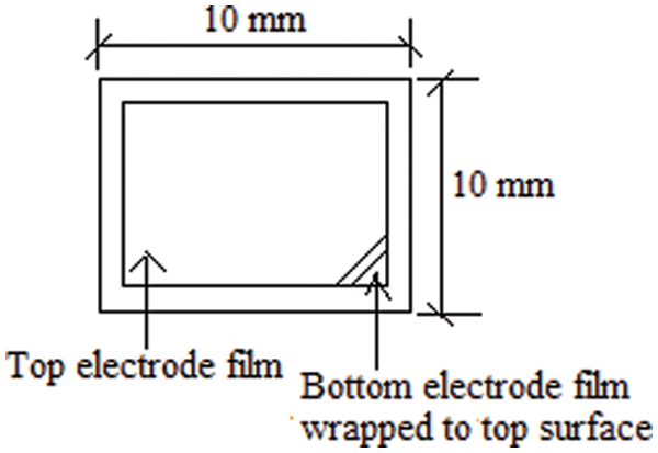
Figure 3: PZT patch size
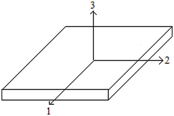
Figure 4: Piezo-electric sheet directions
For the development of infrastructural facilities the piezoelectric materials are broadly considered in many areas. Conventionally, these materials were applied in manufacturing of various sensors to measure the displacement, velocity, acceleration of the structures and actuators to generate the force in the structures. The pressure transduces, strain gauges, vibration sensors are few examples of application of the PZT patch. Though, the piezoelectric materials applied in turbo-machinery as actuators, vibration dampers and active vibration control of stationary/moving structures from decades. Apart from these, the applications of these materials are carried out in the area like absorption of the sound in the water, robotics, fixing the precision positioning and smart skins for submarines. In the present scenario the piezoelectric sensors that are similar to skin, can be used to investigate temperature and pressure. Currently, the piezoelectric materials were used to develop very small scale configurations and wireless inter digital transducers (IDT) using innovative technology of the embedded system, which are applied in area of SHM, micro-electronics and bio-medical [1,18,51–53].
If the force is applied on the structural system, the mechanical impedance in the direction of the applied force is defined at specific point as the ratio of driving harmonic force to the resulting harmonic velocity at that point. The mechanical impedance of structures, Z can be represented mathematically is given in Eq. (4).
To investigate the health of given structural system, the admittance/impedance of the coupled system are determined and calculated impedance system are expressed in terms of conductance and susceptance. A plot of conductance and susceptance with the frequency are generated for prediction of the presence, location and severity of the damages. Impedance of the system having pure mass can be given as, Z = jωm. Likewise, by the Hook’s law, for a pure spring k, the mechanical impedance is represented as,
In EMI technique, the PZT patches are bonded to the considered structure using epoxy adhesive for monitoring the structure. Fig. 5a represents that the PZT transducers primarily performance as thin bar enduring vibrations in the directions of axis and intract througth host structure. The mechanical model of the system and PZT transducers are used as coupled system of specimen connected to linearly vibrating thin bar as shown in Fig. 5b. Application of electric current, E in the direction ‘3’ results expansion and contraction of transducers in the direction ‘1’ [12,13].
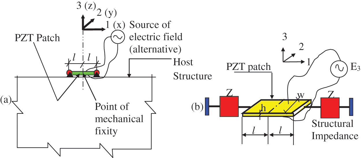
Figure 5: Coupled system of PZT patch and host structure [12]. (a) The surface bonded PZT patch and application of electric field (b) The interaction model of the coupled system of PZT patches and host structure
The one dimentional model of the PZT patch with the host structure is expressed by a differential equation. The represnted defferential equations was derived using the dynamic equilibrium of the intrograted structure and PZT patch. The derived relation is given in Eq. (6). By analysing the Eq. (6) using method of variable separable results Eq. (7).
Appling the boundary conditions as x = 0, u = 0, which results, B = 0. Hence, the velocity and displacement of the PZT patch can be calculated using Eqs. (8) and (9). Moreover, PZT patch and mechanical impedance of structure having axial force is shown in Eq. (10).
where, negative sign shows positive displacement or velocity yields force in PZT transducers [13]. Now, after analysing the values of A and Za are obtained as shown in Eqs. (11) and (12).
The electric current can be obtained by the expression (13), which is defined as the time rate of change of charge.
The electro-mechanical admittance is the inverse of electro-mechanical impedance for one dimensional system can be determined by the Eq. (14).
Following notations are used in this article: c = damping constant; D = electric displacement; d = piezoelectric strain coefficient; E = electric field; F = force; h = thickness of PZT patch;
Investigating structural impedance directly is not possible however the admittance signature can be determined easily using LCR meter. The electro-mechanical admittance signature consist conductance (G) and susceptance (B) signatures, which is the real and imaginary part, respectively. The susceptance signature is less susceptible to crack damage detection instead of conductance signature because the conductance signature has sharp peaks corresponds to vibration mode of structures [33]. Next section consists of latest literatures description associated to the application of EMI technique for SHM.
3.2 Recent Literatures on EMI Technique
Chang et al. [29] reviewed the techniques to monitor the health of interrogated structures. The authors discussed about global health monitoring concept, recent health monitoring technique considered for monitoring the health of infrastructures in USA and various sensors used for SHM such as acoustic approach, X-ray approach, radar technology and fiber optics, respectively. The review article is significant for new research in the area of SHM, however quantification of the damages was not included [54]. Bhalla et al. (2004), developed the concept of the PZT-structure electrostatic interaction model which was depended on effective impedance. The test was performed on an aluminium block of 48 mm × 48 mm × 10 mm size. The authors discussed and formulated the mechanical impedance of structures, piezo-electricity and 2-D electromechanical coupling, PZT-structure interaction, mechanical impedance based on effective impedance and limitations of modeling approaches. The proposed approach is advantageous for the damage investigations at miniature precision of the machinery, aerospace systems and civil infrastructures. Further, the developed approach can be used in several areas like energy conversion efficiency, investigating system response and system power consumption. However, application of the developed technique was not tested on the real structure.
Further, Bhalla et al. [28] applied effective impedance concept for identification of damage using the surface bonded PZT transducers. An RC bridge was the prototype of the RC bridge and aerospace structure were used for validation of the technique. Hence, it was seen that the developed method effectively detect the damages in the structures. Bhalla et al. [40] investigated the model of adhesively bonded PZT transducers. The PZT sensors were bonded to the considered specimen using adhesive which formed a finitely thick layer between considered specimen and PZT patches. The developed force was transferred by shear mechanism producing shear lag. The aluminium block was used for performing the experiment. It was observed that bond layer influence the admittance signature, therefore the developed concept is useful for prediction of the health of structure more accurately. Bhalla et al. [55] discussed about determination of the damages in RC structures due to vibration by the seismic and underground blast. The PZT patches were used for monitoring the RC structure exposed to vibration loadings. For the experiment, the skeleton RC frame was used. RMSD indices were considered for quantification of induced damages. Hence, the significance of the article is that the PZT sensors can be used to investigate structural damages in static as well as dynamic loading conditions.
After that, Lim et al. [56] used PZT patches to diagnosis structural damage and recognition. Three specimens were used, concrete cube, aluminium beam and aluminium truss, respectively for the experimental analysis. RMSD index was used for the quantification of damage. The presented new concept was based on effective impedance which is very useful to determine structural damages for all kinds of structures. Park et al. [57] considered a reinforced concrete beam for experimental study and the same beam was modeled using FEM based software. The RC beam was monitored using EMI technique using the PZT sensors which were bonded on the surface. The progressive damage of size 5 mm × 5 mm was created on beam length of 550 mm at the interval of 50 mm and RMSD was calculated for the quantification of damage of beam specimen. The main advantage of the study is the application of RMSD index to quantify the structural damages. Song et al. [58] reviewed smart aggregate for concrete structures as a multi-functional sensor. The PZT patches were glued on the considered infrastructures for determination of damage. The presented work is helpful for investigations of structural damage, however the method is expensive for SHM. Bhalla et al. [59] considered ultra-low-cost adaption of EMI technique for SHM. The researcher proposed to use instruments such as function generator and digital multimeter instead of cost-intensive impedance analyzer/LCR meter for application of EMI technique. Therefore, it was found that low-cost adoption in EMI technique can be used for industrial application.
Moreover, Shin et al. [60] used EMI technique for online investigation of strength gain in concrete specimen using PZT sensors. The concrete cylinder specimen of height 200 mm and diameter of 100 mm was taken for experimentation and PZT patches have been bonded on the considered concrete specimen. RMSD index was used to predict the strength gain. The advantage of the study is that the strength gain at early age of the civil structure can be evaluated. Yan et al. [42] studied the application of EMI technique using high-frequency. The researcher also discussed EMI technique based on high-frequency excitation for determination of incipient damage. The review article is significant to determine the incipient damages in the structure. Yang et al. [61] used EMI technique to monitor the health of concrete specimen using sub frequency interval approach. The researcher proposed new technique for the determination of severity and location of damage using sub frequency interval 30–400 kHz by calculating their respective RMSD values. For the determination of admittance signature, PZT patches were used. The proposed investigation is useful for the investigation of damage location and severity of damage in concrete infrastructures. Tawie et al. [62] performed experiment on concrete structures to determine the strength gain using EMI technique. The aim of the study was to improve application of EMI technique on real structure using PZT patches. The damages were quantified using RMSD, MAPD and CC indices. From the results, it was observed that the MAPD method was more suitable than RMSD and CC for the determination of strength for all mixes from 3 days to 28 days. The proposed investigation improves the EMI technique for determination of damages, which is useful for monitoring of the real-life structures.
Furthermore, Fan et al. [63] investigated the vibration-based damage characterization technique. It was observed that the vibration-based technique of SHM is more effective to determine the location of the damages. Shanker et al. [3] used EMI technique and global dynamic response technique for the health monitoring of RC structures by dual application of PZT patches as transducers. The researcher proposed new technique for identification of damage present in infrastructures by combining of global dynamic response technique and electro-mechanical impedance technique. Two specimens were considered, one was steel beam of 4 m long and the second one was the steel plate for the experimentation. All type of the damages can be determined using the developed technique. Yan et al. [30] investigated the model of the cracked composite beam using EMI technique and surface bonded PZT sensors. The crack was determined using EMI technique of laminated composite beam. The proposed concept is useful to determine the damage in the composite structures. Na et al. [64] considered EMI technique for monitoring of two epoxy glass fiber composite plates of size 101 mm × 25.4 mm × 2.5 mm made by lap joint with a commercial adhesive using reusable PZT transducers. The RMSD method was used for the damage quantification. It was observed that RMSD value less than 2%, indicate that no damage present in the fiber composite plate. The main advantage of the article is that the application of RMSD index to determine damages using reusable sensors and these reusable sensors minimize the overall expenditure of SHM.
Na et al. [65] investigated the damage recognition method using EMI technique on concrete specimen. The concrete sample of length 500 mm, width 300 mm and depth 50 mm has been taken for experimentation and notches of 300 mm length, 5 mm wide and 5 mm deep were created, which was monitored by series of PZT patches bonded to the host structure. This experimentation proved that the EMI technique can also be used for detection of severe damages in the structure. Verma et al. [66] studied EMI technique for SHM to monitor the concrete structures. The concrete specimen of size 150 mm cube has been used for experimentation and strength gain in curing was monitored. RMSD index was used for the quantification of strength gain. Hence, it was observed that EMI technique to be best suited for curing progress monitoring of concrete structures. Visalakshi et al. [67] reviewed the EMI technique and their recent advances in SHM. The researcher discussed the recent advancement in the field of corrosion of reinforcement, modeling of coupled piezo structures interaction through the bond layer, integrated SHM and energy harvesting and biomechanics, respectively. Kaur et al. [68] investigated the embedded piezo concrete vibration sensor (CVS). The combined energy harvesting and SHM potential have been evaluated. The 4.0 m RC beam was used for experimental analysis. CVS sensors and surface-bonded sensors were used in RC structure for health investigation. Hence, application of CVS sensors for energy harvesting and SHM of RC structures proved new contribution.
T et al., examined strength gain in the concrete using EMI technique and smart aggregate. The embedded sensors were used for determination of strength gain in concrete. The changes in impedance signatures indicate strength gain in the concrete which was monitored by smart aggregates. The various statistical indices were used for quantification of the strength gain viz., RMSD, MAPD and CC, respectively. For the verification of the results, 1.5 m concrete beam was considered for experimentation. Sensors were used in series/parallel combination which results reduced data collection. The quantification of the induced damages was evaluated. It was observed that experimental results agreed with the actual severity of the damage [69]. Talakokula et al. [70] observed chloride-induced corrosion assessment of reinforcement using surface-bonded PZT sensors and inserted PZT patches of reinforced concrete structures. PZT sensors have been bonded to the rebar surface and embedded in the concrete area near to rebar. Embedded transducers CVS measured the changes in the parameters due to ingress of chloride in the concrete. However, corrosion-induced damage due to chloride was measured by the surface bonded PZT sensors. Hence, it was found from the experimental results that both sensors were compliment to each other for the assessment of rebar corrosion. The concrete specimen of sized 150 mm cube was considered for experimental verification.
Subsequently, Guo et al. [71] used EMI technique to monitor the health of concrete structure using embedded PZT sensors and discussed practical issued related to the technique. The impedance spectra were evaluated by RMSD technique. The mortar specimen of depth 40 mm, width 40 mm and length 160 mm was cast for the experimentation. Further, from the results, it was observed that increasing distance between PZT patches and mass loadings, the sensitivity to the damage detection decreases in the RMSD chart. Basic advantage of the research was that sensing range of the PZT patch was evaluated which can be useful for the determination of number of sensors required in the monitoring of structure. Liang et al. [32] studied bond-slip evaluation using EMI technique of concrete-encased composite structure. The PZT sensors were glued on the surface of concrete sample. The researcher has considered an I-shaped steel section and two concrete blocks as a composite specimen in the structural member in a building. RMSD index was used for quantification of damage due to bond-slip between concrete and steel. Numerical and experimental investigations were done using EMI technique to investigate the health of the composite structures, which is significant research in the field of SHM.
After that, Talakokula et al. [72] investigated corrosion origination and carbonation in the concrete structure using EMI technique. The concrete specimen was considered and it was exposed to carbon dioxide under the controlled condition for the period of 230 days. PZT transducers were bonded on the reinforcement to determine the carbonation induced corrosion which was indicated by admittance signature. As corrosion started in the concrete specimen, the equivalent stiffness was determined and it was observed that its value was less compared to the healthy state which indicates corrosion of reinforcement. Corrosion in the RCC structures is the core concern throughout the world, hence the proposed method can be used for the determination of corrosion in the industrial structures. Tzoura et al. [73] compared equivalent strengthening system of concrete element retrofitted with textile-reinforced mortar (TRM) or fiber-reinforced polymer (FRP) using EMI technique. RMSD and Ry/Rx index were used and observed that the RMSD index was more suitable for damage detection. The quantification of the damages can be carried out more accurately using proposed method.
Additionally, Feng et al. [74] discussed a method for monitoring of structures using EMI technique. The researcher was used concrete beam width 150 mm, depth 150 mm and length 500 mm and PZT sensors were bonded to concrete beam at different locations for determination of damage. Admittance signature was used for determining the presence of damage; variations in admittance signature indicated the existence of damage. Kaur et al. [75] used multiple piezo configurations to evaluate the reinforced concrete structure for optimal health monitoring using EMI technique. The researcher used different types of sensors configuration, namely, modified dual piezo configuration, embedded single piezo arrangement, surface-bonded single piezo arrangement and metal wire single piezo arrangement in EMI technique for SHM of RC specimen exposed to NDT evaluation. For quantifying damage severity, the surface-bonded single piezo configuration was found more suited in terms of equivalent stiffness parameter. Whereas, embedded single piezo configuration and metal wire single piezo configuration were used to correlate the global dynamic stiffness of the structures. Therefore, the researcher observed that overall proposed integration more suitable for early detection of damage.
In continuation, Haq et al. [76] considered a reinforced concrete column for fatigue damage evaluation using EMI technique. The two RC columns of size 1.4 m length, 150 mm width and 150 mm depth were cast and vibration was applied by shake table till failure of the column. PZT sensors were used as CVS for the assessment of the fatigue damage. The natural frequency was a direct measure of stiffness which was considered for the assessment of damage, as damage increases the stiffness of the RC column decreases. A formula was derived for the RC column under the shake table vibration for fatigue damage assessment, which is useful to determine the damage in the structure due to fatigue. Yan et al. [77] examined enhancement in structural health monitoring using wireless smart aggregate. The wireless smart aggregate was used for concrete crack detection (CCD) and it was validated the effectiveness of proposed methodology by experimentally. Moreover, the investigated system was wireless and power-efficient, hence, suitable for complex environment constructions sites.
Fan et al. [78] carried out experiment on RC column for determination of the damage which was induced due to impact loading. The EMI technique was used and PZT sensors were bonded on the host structure. RMSD was calculated for the quantification of damage; however it did not truly provide quantitative information regarding the structures. For better information related to damage, the damage volume ratio was used, which was obtained by simulation. Impact loading was applied to the host structure by free fall of steel balls. Experimental and numerical evaluation of damage was carried out by considering the impact loading on concrete structure of length 400 mm, width 100 mm and height of 100 mm, respectively. The admittance signature was measured to evaluate the damage present in the specimen. The main advantage of proposed investigation is that damage due to impact loading can be recognized using EMI technique.
Ai et al. [79] performed experiment on 2.0 m reinforced concrete beam and the four-point loading was applied to the specimen. The structural tension and compression have been measured at bottom and top of specimen using the EMI technique by surface-bonded PZT sensors. Stress-induced damage was measured. Impedance and admittance signature were evaluated and correlated with baseline signature. In Fig. 6 the variation of conductance signature vs. frequency under varying loading condition has been shown. The significance of the investigation is that the presence of damage can be determined by evaluation of shifting of the peaks in the signatures. Fig. 7 represented the changes in conductance signature with different frequency ranges under different loading condition. It was observed that as the load increases the damage level in the specimen also increases and conductance signature shifted towards the left side.
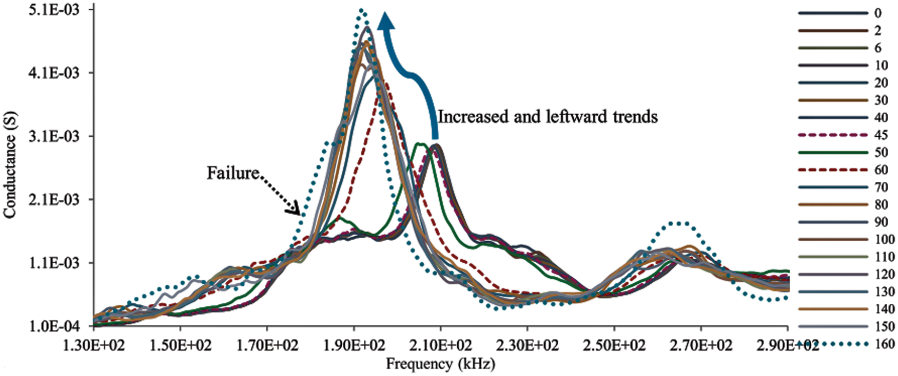
Figure 6: Conductance vs. frequency under different loading condition [79]
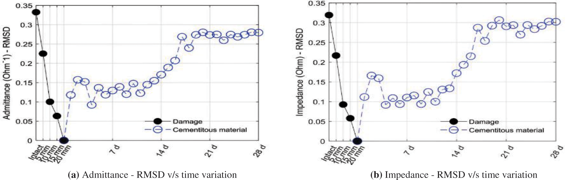
Figure 7: Variation in healing of damage with cementitious material vs. time [89]
Li et al. [80] monitored the interfacial bond-slip using EMI technique on fiber-reinforced polymer rebar reinforced concrete. The size of concrete specimen of 150 mm cube and CFRP rebar of 600 mm length and 10 mm diameter has been considered. The specimen was prepared using carbon fiber reinforcement rebar and the concrete. The pull-out test has been conducted for bond-slip phenomenon between carbon fiber reinforcement and concrete, respectively. The impedance and admittance signature were measured at time of debonding damage. The statistical indices like RMSD and MAPD have been applied for quantification of bond-slip damage. The advantage of the proposed experimentation is that slip in the bond can be monitored using the EMI technique and prior indication of the slip can be predicted if the bond is monitored continuously. Li et al. [81] used EMI technique for bond-slip monitoring of FRP shear strengthened beam by numerically and experimentally. The PZT transducers were bonded on the beam specimen. The researcher considered 7.0 m real-sized simply supported beam structure and the two-point loading had been applied for debonding monitoring. FRP jacket was used in two different patterns, namely, U-jacketed beam and cross-section of the fully wrapped beam. The PZT patches have been bonded at different locations for the determination of debonding of FRP from the beam structure. Admittance and impedance signature have been measured for the evaluation of debonding. RMSD was determined for the quantification of debonding damage. From the literature, it was observed that at 10% RMSD value represents the initiation of debonding and at 20% RMSD value indicates severe debonding. Thus, the proposed concept can be used for quantification of slip in the bonding.
Visalakshi et al. [82] considered a reinforced concrete structure for monitor the damage which was induced due initial phase hydration. The PZT sensors were bonded on the surface of the specimen and EMI technique was used for monitoring. The researcher has used six RC cylindrical specimens of sized 100 mm length and 70 mm diameter for the monitoring of early age hydration. The equivalent stiffness was derived by considering the PZT sensors as non-dimensional hydration parameter. To find out changes into raw parameters, the RMSD index was determined. The importance of the developed concept is that the early phase hydration in the concrete can be evaluated. Ayyildiz et al. [83] used three structures namely RC structure, concrete element and masonry building for the damage monitoring using EMI technique. Moreover, it was observed that the PZT sensors are more effective and cost effective for damage detection. The RMSD was calculated for finding the presence of damage. The web interface processed the analysis and data was collected. The proposed investigation proved that the PZT sensor is more sensitive to damage compared to other existing sensors.
Dhawan et al. [84] considered a ten storeyed reinforced concrete structure contrary to wind and seismic loads and expected residual service life was determined from the current strength consideration. For residual service life, the essential current parameters like cross-sectional area of concrete and steel, in situ material strength, namely concrete and steel, and Young modulus of elasticity were determined. The rigorous methodology was developed for the expected residual life determination against the wind and earthquake loadings using current parameters of the structures. The expected residual life was found 30 years against the wind loading and 20 years under earthquake loading. Hence, it was found that the overall residual life of RC structure under wind and earthquake consideration was 20 years. The residual life of real structures can be investigated using developed concept. Balamonica et al. [85] connected PZT sensors in series and parallel combination for determination of damage progression in concrete infrastructures. The researcher considered RC beam of 1.2 m length and the embedded PZT sensors were used for identification of damage though admittance signature. For damage quantification RMSD, MAPD and CC were used. It was observed that location of damages in the structure was determined more accurately by combining the sensors in series or parallel.
Kaur et al. [86] proposed a method for damage detection and subsequently retrofitting of RC structure accompanied by fatigue and long term strength monitored by EMI technique using embedded PZT sensors. The researcher used higher-order derivative of displacement and curvature for damage detection and retrofitting of the structure. For the experimentation a 4 m RC beam was cast and the CVS were placed at 19 locations inside the beam as well as at top and bottom. The damage was monitored at six different damage stages like pristine stage 1 (no damage in the RC beam), damage stage 2 (Chipping off the concrete from the notch), damage stage 3 (Damage 1 plus damaging 50% reinforcement in the beam section), damage stage 4 (Damage 2 plus damaging 100% reinforcement in the beam section), damage stage 5 (Welding of 100% reinforcement bars) and damage stage 6 (Retrofitting 1 plus filling the notch with concrete), respectively. The natural frequency was used for finding the presence of damage in the real sized RC beam. Fatigue behavior of the sample was examined with proposed concept and result was found satisfactory. The proposed method can be used to determine the damage induced due to fatigue. Liao et al. [87] monitored the space reinforced concrete frame structure under seismic loading condition using piezo ceramic-based sensors. The one way two-story RC frames were considered for an experiment under the earthquake loading. The presence and location of the damage were determined and compared with the actual location of the damage. The sensitivity of the PZT sensor for determination of the damage was found satisfactorily in the case of vibratory loading. Na [88] used EMI technique to monitor the deboning of layers using PZT patches of composite structure. The admittance signature was determined at the time of debonding of the layers which showed that the debonding phenomenon of structures. The RMSD index was used for the quantification of debonding of the layers. The debonding of layers in composite structures can be quantified using EMI technique.
Kim et al. [89] applied the EMI technique for damage/flaw renovator in concrete specimen using PZT transducers bonded on the surface and performance evaluation method had been established. A concrete specimen of length 250 mm, width 125 mm and depth 150 mm had been considered for monitoring. The damage had been created by machine cutter at depth varies from 5 mm to 20 mm at the interval of 5 mm at the centre of the specimen. To repair the crack, the researcher had used two self-healing materials made in Republic of Korea named as power type filler and liquid type reactants. It was observed that EMI technique displayed that self-healing material used exhibit continuing recovery over time in admittance and impedance signature. The damage statistical indices have been applied for damage indicators and were found that the RMSD, MAPD and CCD have similar damage data; however Cov method was not adequate to damage similarities. The damage index methods were more effective to damage indicator in the optimal frequency band of 50 kHz–99.9 kHz. Figs. 7a, 7b shows the admittance and impedance signature of RMSD healing of damage with cementitious material with respect to time (days). The variations in impedance and admittance were found similar in RMSD, MAPD and CCD however, different in the value of Cov. The investigation is useful for determination the strength gain after healing of the generated damage in the structures.
Yan et al. [90] considered EMI technique with surface bonded and embedded PZT patches for interface investigation of steel-concrete-steel sandwich structures. The acoustic emission method (AE) and the EMI technique were used for determination of the damages. AE method was used for the detection of the initiation of micro crack and indicates damage severity, types and location. The EMI technique has been used for the determination of damage due to bond-slip which is not visible. The real-sized RC simply supported beam of 4.572 m was considered and admittance signature had been determined. The variations in admittance signature were indicated the existence of damage. The EMI technique was successfully applied on real structure for SHM. Han et al. [91] monitored health of timber specimen using EMI technique. The damage location factor and damage size factor were formulated by the researcher. Author used five set of timber specimens of length 200 mm, width 60 mm and thickness 17 mm for damage investigation. The circular PZT patches of sized 10 mm diameter and 2 mm thickness were used. The four artificial damages of circular shape having diameters of 4, 6, 8, and 11 mm were induced at a distance of 40, 60, 80, and 100 mm respectively from the bonded PZT patch. It was observed from the experimental results that the frequency range from 150 kHz to 300 kHz is more effective for damage investigation of a timber specimen using EMI technique. The impedance signatures were determined for damage investigation that can be used to investigate the quality of timber for industrial uses.
Pan et al. [92] examined strength of cement mortar using piezoelectric cement (PEC) sensor based on EMI technique. The three cement mortar cube of size 50 mm were used with different water-cement ratio such as 0.40, 0.50, 0.60 and the compressive strength were determined after 1, 3, 7, 14, 21, 28, and 56 days, respectively. Further, the result were investigated and it was observed that PEC sensor and PZT sensor behavior is similar for determination of the compressive strength. However, it was found that the PEC sensor is more effective than PZT sensors in the terms of monitoring capability. According to author, the PEC sensors can be used for investigation of cementitious materials only.
Su et al. [93] developed new EMI technique based methodology for direct investigation of strength gain from cementitious materials using PZT sensor. The author used phase angle spectrum to extract three features such as resonant frequency of the first local phase angle peak (PARF), local phase angle peak value (PA), and the corresponding width of half-prominence (HPW) for the strength gain. To evaluate the strength gain, the five numbers of different 50 mm cement cube specimens with varying water cement ratio ranges from 0.46 to 0.38 were considered. Two stages were considered that is very early age (4 to 8 h) and early age (1, 3, and 7 days) for the application of EMI technique and destructive cube test. From these three indicators, the PARF was found more reliable than others. Further, the FEM method was used to develop correlation between stiffness of host structure and features obtained PARF indicator. The proposed concept can be used to investigate the strength gain of the real life based infrastructures. Li et al. [94] monitored corrosion using circular piezoelectric metal transducers and EMI technique by numerical modeling. Two PZT transducers of diameter 30 mm and 40 mm with thickness of 0.5 mm were used. The results of FEM methods and experimental investigations were conducted to validate the results. According to the author, the developed technique to determine corrosion has the benefits such as low cost, linear quantitative corrosion assessment, and online and remote monitoring.
Hamzeloo et al. [95] considered L-shaped aluminium structural beam with a crack and damage was determined using EMI technique. The theoretical and numerical approaches were used to determine damage using embedded piezoelectric wafer active sensor. Author was considered two beam specimens of same cross section (25 mm × 3 mm) and different lengths as 275 mm first part and 300 mm second part for experimental damage investigation. The experimental and numerical results were agreed and it can be used for health monitoring of different kinds of structures. Liu et al. [96] considered lamb wave and EMI technique using reusable piezoelectric transducers for SHM. The reusable PZT transducers were glued on the aluminium plate specimen by ethylene acrylic acid copolymer with an aluminium enclosure. Further, the reusable PZT sensor was used to determine corrosion damage, which was removed from the test specimen and reused for corrosion damage assessment of the aluminium plate. From the test results, it was observed that the damage induced by corrosion can be successfully evaluated using reusable PZT patch and PZT patch can be reused several times for damage detection.
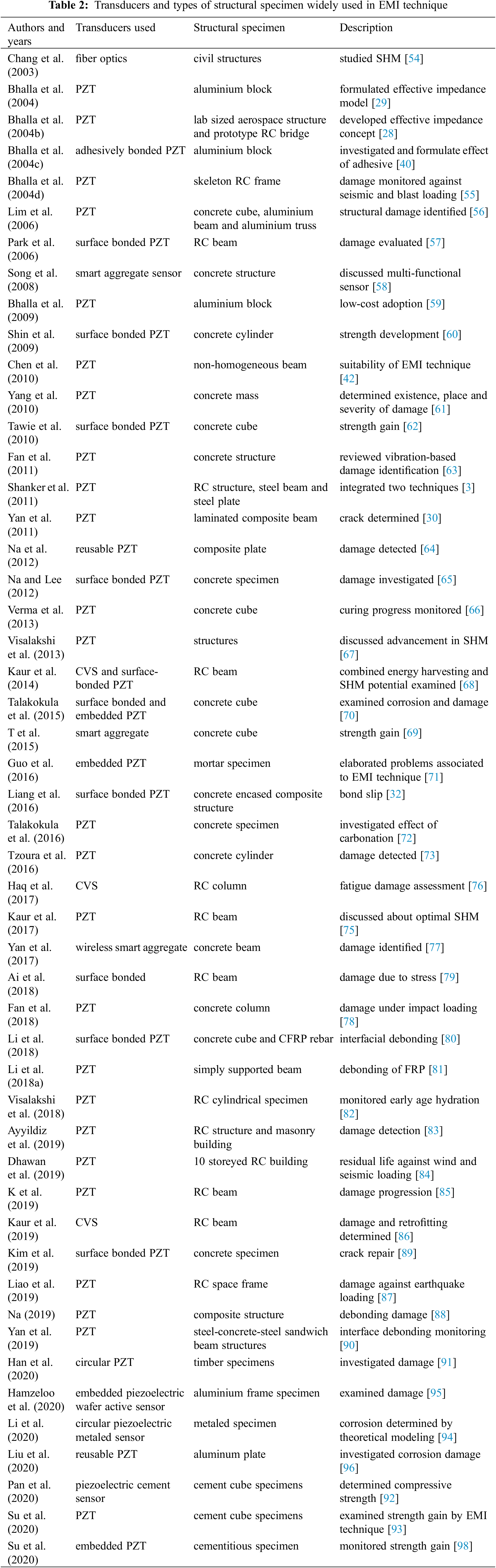
The recent literatures related to EMI technique and suitability of the technique for different types of structures are discussed in Table 2. Moreover, it also covers the type of sensors and specimen used in EMI technique. Fig. 8 has been described the number of publications vs. years with respect to EMI technique used in the field of SHM, the data considered [97]. It was observed that the development of research related to EMI technique is going on in the present scenario. In the next section, quantification of damage index and related recent literatures has been discussed.
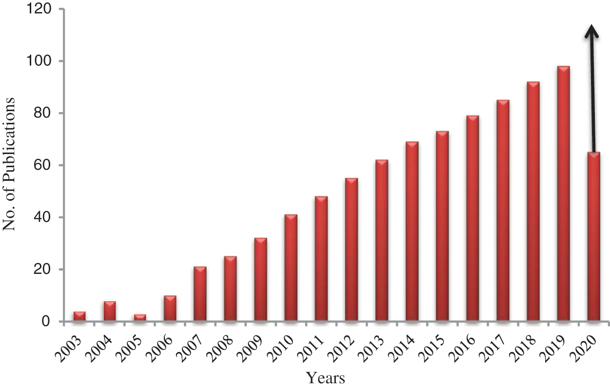
Figure 8: No. of publications vs. years
In EMI technique, presence of damage in infrastructures indicates variations in signature from baseline signature [3,28,29,40]. The lateral and upward movement of peaks and new peaks appearance in conductance signature is the primary indicator of damage [12]. For quantification of damage in EMI technique the statistical methods were used by several researchers’ viz., root mean square deviation (RMSD), relative deviation (RD), mean absolute percentage deviation (MAPD) and correlation coefficient (CC), respectively. According to Giurgiutiu et al. [99], the RMSD index is as shown in Eq. (15).
where,
where, damage location, 1 shows the deviation from selected base line point in the denominator and in numerator signifies the mean square deviation at ith location. Furthermore, MAPD method is referred by Naidu [100], which is shown in Eq. (17). Another one the covariance and the correlation coefficient are formulated as shown in Eqs. (18) and (19).
where, the standard deviation at reference point signature and signature after damage represented by σ0 and σ1 and the mean value of baseline healthy state signature and signature afterward damage represented by
Waveform chain code (WCC) technique, signature assurance criteria (SAC), equivalent level of degradation system (ELODS) and adaptive template machine (ATM) are based on numerous pattern recognition techniques to calculate the changes in infrastructural signature due to damage reported by [101,102]. In present situation, use and application of statistical indices for quantification of damage in the field of SHM is going on a broad scale. The literature related to the quantification of damage has been described in the below section.
4.1 Recent Literatures on Quantification of Damage
Recent literatures in respect to the quantification of damage were considered and elaboration has been made. Several researchers/authors were used different methods for the quantification of damage. Tseng et al. [103] considered prototype RC bridge specimen and three cyclic loadings were applied to structure. The EMI technique was applied to investigate the health of prototype RC bridge specimen. The surface-bonded PZT patches were used for determination of damage signature of structure. The cracks developed under the cyclic loading were quantified by statistical method RMSD. The main advantage of the proposed method is that the quantification of damage can be done using EMI technique. Park et al. [4], described an outline on piezoelectric impedance-based SHM. The experimental and theoretical aspects were discussed, corresponding to literature. The EMI technique was applied for the determination of damage in the structures. The researcher reviewed the suitability of damage quantification methods viz., RMSD, MAPD, Covariance and CC, respectively and got in order to RMSD and MAPD much appropriate for prediction the presence, location and severity of the damage, however Covariance and CC are best suited in computing the rise in damage severity at a fixed position. The review article signifies the use of damage indices for the determination of presence, location and severity of damages in the real structures.
In addition, Park et al. [57] considered a reinforced concrete (RC) beam for experimental study and the same beam was modeled numerically using the finite element method (FEM) based software. The EMI technique was applied to monitor RC beam by surface-bonded PZT sensors. The progressive damage of size 5 mm × 5 mm × 150 mm was created on beam length of 550 mm at the interval of 50 mm and RMSD method has been applied for quantification of damage in the beam. Lim et al. [56] considered three structures viz., concrete specimen of cube sized 150 mm with surface bonded PZT patch of length 10 mm, width 10 mm and depth 0.30 mm, aluminium beam of length 231 mm, depth 27 mm and width 27 mm with surface bonded PZT patch of length 10 mm, width 10 mm and depth 0.20 mm, and aluminium truss of length 950 mm and height 300 mm with surface bonded PZT patch of length 15 mm, height 15 mm and width 0.5 mm. The EMI technique was applied to extract the signature of structures at damage states as well as healthy state. Further, for the quantification of damage the RMSD method was applied by researcher.
Shin et al. [60] described that EMI technique is more susceptible for early age strength progress of a concrete specimen. The researcher considered a concrete cylindrical concrete sample of diameter 100 mm and height 200 mm and early age strength was determined using PZT patches bonded to the concrete specimen. RMSD index has been used for the quantification of strength gain, as the strength increases RMSD value increases. Bhalla et al. [59] outlined novel low-cost hardware system instead of costly equipment like impedance analyzer/LCR meter for the SHM using EMI technique. The aluminium block was considered and RMSD method was used for the damage quantification. The result obtained using the suggested hardware permits investment of less than $2500. The low cost monitoring system was developed for SHM.
Further, Yang et al. [61] considered the EMI technique to investigate infrastructural health using PZT patches and RMSD method for determination of presence, location and severity of damage, respectively. The researcher was suggested a new methodology to determine location and severity using RMSD method by separating high range frequency (30–400 kHz) into sub frequency gaps. The sub frequency RMSD values have been considered to examine position and severity of damage of interrogated specimen. Tawie et al. [62] considered a concrete cube with different mix designs and the EMI technique was used for strength gain. The PZT sensors have been bonded on the concrete cube for monitoring of specimen. Statistical methods RMSD, MAPD and CCD have been applied for determination of gain in strength and the correlation has been made with experimental data. From the result data, researcher observed that the MAPD method is best suited than RMSD and CCD methods for strength gain evaluation.
Na et al. [64] applied EMI technique to monitor the two epoxy glass fiber composite plates of size 101 mm × 25.4 mm × 2.5 mm, joined by lap joint with a commercial adhesive using reusable PZT transducers. The RMSD method was used for the damage quantification and observed that RMSD value less than 2%, which indicate that no damage present. Na et al. [65] discussed about the improvement in damage identification quality of EMI technique for the concrete specimen. Concrete sample of length 500 mm, width 300 mm and depth 50 mm has been considered and artificial damage of length 300 mm, 5 mm wide and 5 mm deep in form of notches were induced, which was monitored by series of PZT sensors bonded on the concrete specimen. The damage was computed using RMSD method and found that change in signature from baseline signature.
Furthermore, Kaur et al. [68] proposed a new research related to energy harvesting and SHM, which was proved by experimental demonstration using embedded CVS in RC structure. The RC beam of length 4 m was considered for the experimentation and CVS placed at different locations. The contact and inertial type shakers were used for the vibration. The RMSD curves were plotted against the different damage conditions and the method was used for the quantification of damages. The developed methodology related to energy harvesting and SHM are useful for real-life structures, further the harvested energy can be reused to monitor the structures when needed like power system for sensors. Talakokula et al. [70] considered the surface bonded and inserted piezo transducers for corrosion evaluation of RC specimen. The CVS and surface-bonded piezo sensors (SBPS) were used and the curve has been plotted between the RMSD and days considering both the sensors. The experimental result shows that both sensors complement each other. The RMSD values were used for the corrosion assessment of the RC beam structure. The corrosion is the serious issue related to the structures exposed to the environment, hence corrosion can be determined using EMI technique in real structures.
Saravanan et al. [69] measured strength development in concrete structure by smart aggregate. Concrete specimen of size 150 mm cube was made and two smart aggregates were embedded. The three statistical methods were used for strength development in concrete structure viz., RMSD, MAPD and CC, respectively. Guo et al. [71] discussed about the practical use of EMI technique for examination the health of considered concrete specimen using PZT sensors. The cement mortar cube of depth 40 mm, width 40 mm and length 160 mm was used for experiment. The sensors were bonded to the host structures and load was applied and signatures were extracted. The RMSD index was calculated for differentiation of damage signature.
Liang et al. [32] determined debonding of concrete-encased compound infrastructure using EMI technique by PZT sensors, which was attached on the surface of considered structure. The two concrete specimens were encased with steel and load was applied on the structure. The bond slip amid steel and concrete was estimated. The RMSD index was used to quantify the bond-slip damage. Tzoura et al. [73] considered two concrete specimens which were retrofitted with textile reinforced mortar (TRM) and fiber-reinforced polymer (FRP) jackets and monitored using PZT patches and comparison of their strengths had made. The damage has been evaluated using RMSD method and Ry/Rx index, respectively. It was observed from results that Ry/Rx index have less reliability than the RMSD index in respect to damage quantification.
Moreover, Talakokula et al. [72] used EMI technique to determine carbonation induced corrosion which was initiated and propagated in RC structures. The PZT sensors were bonded on surface of the rebar specimen. RMSD index was determined for quantification of damage due to bond slip. Kaur et al. [75], considered real-sized reinforced concrete structure to integrate and evaluate the optimum health using different variant, namely, surface-bonded single piezo configuration (SSPC), embedded single piezo configuration (ESPC), metal wire–based single piezo configuration (MWSPC) and modified dual piezo configuration (MDPC), respectively. The RMSD values were determined for different damage conditions using corresponding damage signatures of RC structure. The integration of different indices is advantageous for the investigation of incipient damages and prediction of their severities.
Fan et al. [78] used EMI technique for damage evaluation under impact loading of the concrete column. The PZT patch which was bonded on the surface had been used to measure variation in admittance signature of structure and has been considered to establish a relationship with RMSD method. However, the RMSD index was not best suited in this case; therefore the damage volume ratio was determined, which predicted the better damage level in the structure. Visalakshi et al. [82] implemented EMI technique for the determination of early hydration of concrete structures using PZT patches bonded on the reinforcement. The early hydration was measured from early hours till 28 days continuously. The changes in admittance signature showed the early hydration. The RMSD variation with age was given the variation in the early hydration. Li et al. [81] considered EMI technique for debonding monitoring of FRP shear strengthened beams by experimentally and numerically. The researcher was taken real-sized 7.0 m length reinforced concrete beam which was strengthened using FRP by two different types like U-jacketed and fully wrapped, respectively. The RMSD index was used for determination of de-bonding of FRP from the RC structure. It was observed that RMSD index was increasing by de-bonding.
In continuation, Ai et al. [79] used a 2 m RC beam under the four-point bending load and EMI technique was applied for monitoring tension/compression at bottom/top of the beam induced by applied load and damage using the PZT patches at specific locations. The variations in conductance and susceptance signature were represented crack formation in RC beam. RMSD index was used for the quantification of induced stress and damage due to stress. Li et al. [80] considered concrete cube fabricated with carbon fiber reinforced polymer (CFRP) rebar and pull out test was applied. The debonding between the concrete and rebar was measured using EMI technique. The RMSD and MAPD indices had been used to measure the variations in impedance signature due to debonding phenomenon in the concrete specimen. Balamonica et al. [85], considered the series and a parallel set of PZT patches for damage identification of an RC structure. RMSD, MAPD and CC indices were used for the damage quantification from the signature of the structure.
Yan et al. [90] taken the steel-concrete-steel sandwich structure and PZT sensors were used for monitoring the interfacial debonding. EMI technique was used to determine the debonding of steel and concrete composite structure. For the experimental analysis, an RC beam was cast and presence of damage has been determined. The damage was quantified using the RMSD method. Kaur et al. [86] considered reinforced concrete beam structure alongside long terms strength monitoring and fatigue strength by PZT patches. Also the beam was retrofitted after damage and monitored. The damage was analyzed at three stages like pristine state, damage state and retrofitted state, respectively. For the quantification of damage RMSD index was used. Kim et al. [89] applied EMI technique using PZT transducers for evaluation of crack renovation in concrete infrastructures. The RC beam was taken and artificial damages were induced. The RMSD, MAPD and CC methods were used to the quantification of damages. Tinoco et al. [104] considered the RMSD method for the quantification of damage and RMSD was used for calculation of modulus of elasticity of different structures. The EMI technique was applied for investigating the damages in the structures. The advantage of the above concepts is that EMI technique had been established for determination of presence, location and severity of damages in the structures.
Han et al. [91] considered EMI technique for the monitoring of timber specimen. The two factors were determined for the investigation of damage using circular PZT patches and EMI technique such as damage location factor and damage size factor. For the investigation of severity of damage, the RMSD index method was used. Haq et al. [105] investigated fatigue damage and residual fatigue life of RC frames structure using PZT transducers. The RMSD index method was used for the damage assessment of a considered structure. Zhang et al. [106] investigated stiffness degradation of a hardened cement paste under uniaxial compression loading using EMI technique. Conductance signatures were determined for the analysis of degradation in stiffness. Statistical methods such as RMSD, MAPD, and CC were used to quantify the stiffness degradation. It was observed that the CC index method is best suited to investigate the stiffness degradation of a hardened cement paste. The basic advantages of this research work are the prediction of remaining life of the structures after damages.
Hence, the statistical methods in the present scenario are best suited for the damage quantification using EMI technique. RMSD method not only for damage quantification but has also been used for determination of carbonation, corrosion, strength gain, pipe loosening and rate of hydration. The statistical methods used in EMI technique and described the application of methods are shown in Table 3. The use of statistical methods in EMI technique is shown in Fig. 9. It has been seen that the RMSD method is most widely used statistical method. It is used 60% of the total application of statistical methods as compared to various methods like MAPD, CC, Cov and others as approximately 20%, 10%, 5%, and 5%, respectively in the EMI technique. The researchers used various combinations of statistical methods for the damage assessment viz., RMAD plus MAPD, RMAD plus MAPD plus CC, and RMAD plus MAPD plus CC plus Cov that are approx. 65%, 48%, and 37%, respectively.
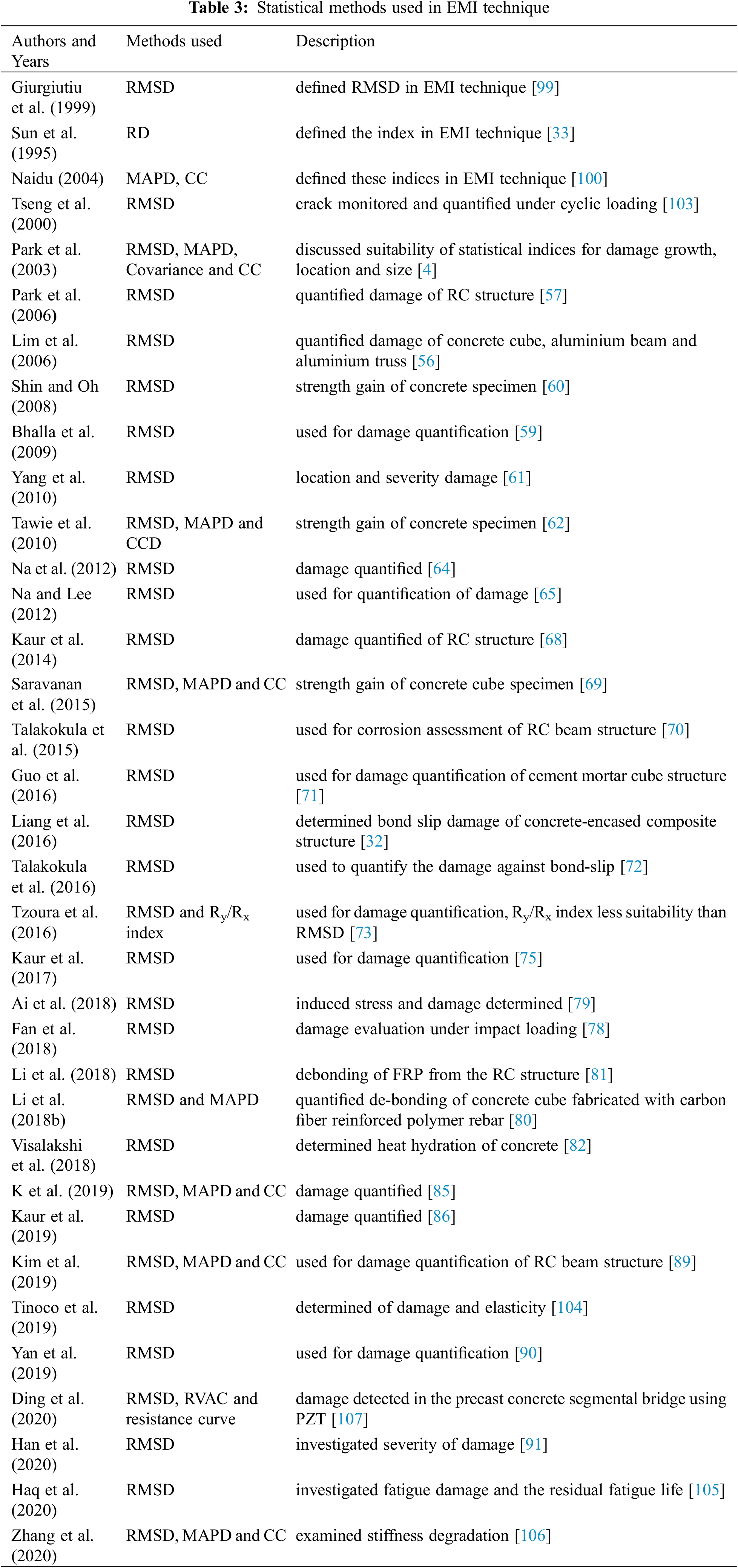
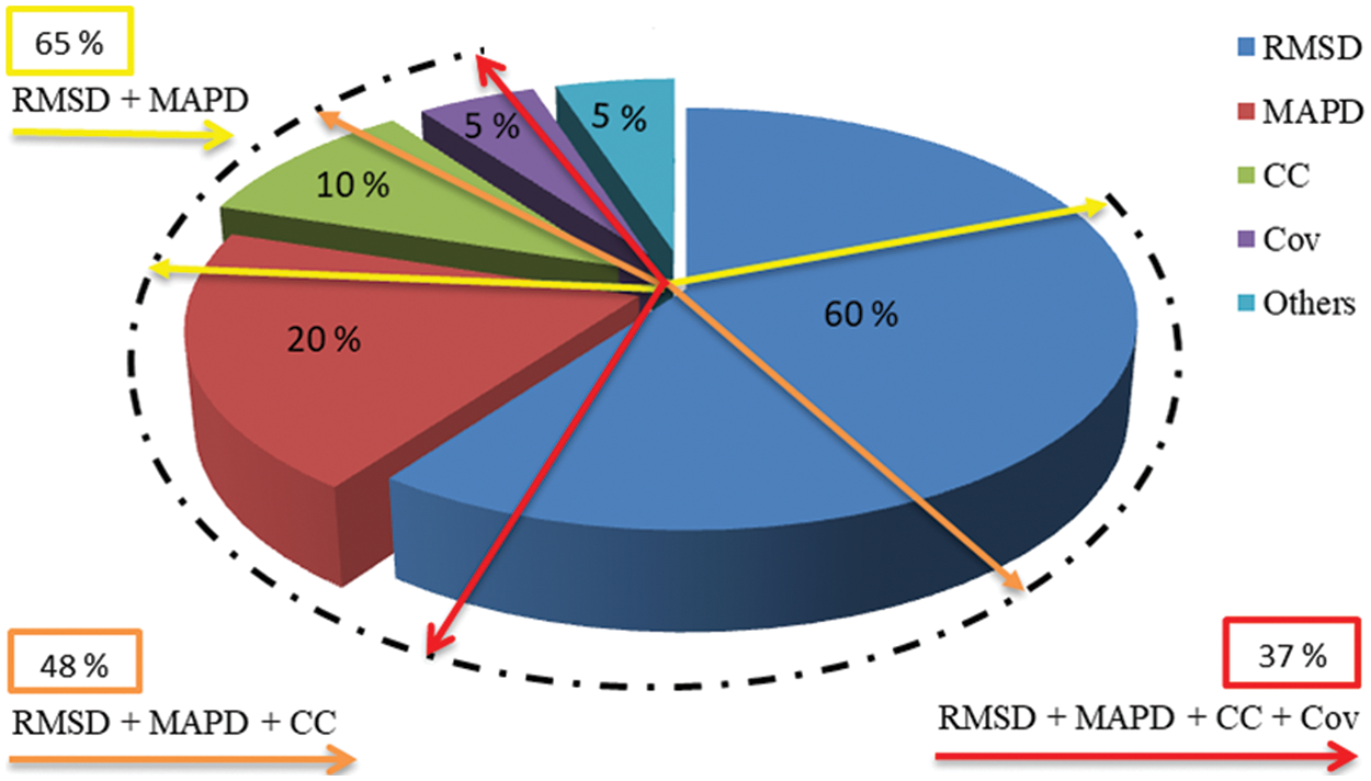
Figure 9: Statistical methods for damage quantification in EMI technique
1. The investigations related to PZT patch can be performed to harvest energy from our shoes related to our everyday activities using piezo-based devices inserted in our shoes which can be used to power personal viz., mobile phones, watches, i-pods and even laptop computers, etc.
2. The investigation of state of bones after an injury or throughout their healing can be studied using micro piezo materials and this can be part of diagnostic system.
3. Actual time prognostic of many ailments on diseased humans should be investigated using micro-sized piezo-based devices which are same as concept of structural health monitoring of infrastructures.
4. The real movement of artificial limbs in peoples anguish from different types of inabilities can be investigated using piezo-actuators.
5. Several studies have been done on square size PZT patches. The use of different shapes of PZT patches like circular, triangular, trapezoidal, hexagonal etc. should be investigated with respect to the behaviour and implementation in EMI technique.
6. The PZT patches have limited range of sensing zone for the different materials. The investigations should be studied on the factors which are accountable for this variant.
7. The investigation should be performed in the changes of signature of PZT patches due to the age variation. The correlation can be investigated between deteriorated signatures with time.
8. Algorithm should be developed for the investigation of damage location exactly.
9. The real and imaginary part of PZT patches are used for extraction of equivalent parameters and these parameters are in respect to the frequency, not associated to the physical properties of infrastructures. Thus, the correlation should be investigated between the physical parameters such as damping, stiffness and equivalent parameters.
10. The statistical methods are used in EMI technique for the quantification of damage. The new method should be developed for the quantification of damage.
11. The quantification of damage has been studied however; there are no boundary conditions available for the differentiation of incipient, moderate and severe damages. The quantified boundary conditions should be studied.
12. The application of EMI technique on structural timber is limited. The studies can be examined using EMI technique on large timber specimens for different size of cracks or holes and also can be considered various experimental conditions such as temperature, humidity and boundary, etc.
13. The studies have been performed to investigate damage using statistical methods in EMI technique which required baseline healthy state signature data. The novel methods should be developed for the damage investigation without baseline healthy state signature data using PZT sensor using EMI technique.
A detailed overview, that has been presented to detect and locate the damages and quantification of damage in structures using EMI technique reflect the state-of-the-art. Damage in structures leads to catastrophic failure, therefore sustainable construction needed for the development of infrastructures. Several factors have been covered which are responsible for damages in the structures viz., cracking, freeze and thaw, fire, corrosion, and concrete spalling. Furthermore, from these factors cracking is more accountable for structural collapse, because it provides a way to ingress harmful ingredients in the concrete structures. Therefore, need to protect the structures from the collapse, which allows health monitoring of structures for establishing the integrity of structures. Several statistical methods were discussed, MAPD, CC for the quantification of induced damages in structures such as RMAD and Cov, respectively. Hence, it was observed that the RMSD index is commonly used by researchers for the quantification of damages in structures. Subsequently, the MAPD method is applicable more than other methods like, CC and Cov for the quantification of damages. Moreover, it is observed that these statistical methods cover to quantify several parameters like, corrosion rate, strength gain, loosening of connection, bond-slip, and modulus of elasticity, etc.
Further, the comprehensive description of EMI technique has been presented in this review research paper. Smart materials like PZT patches formation, formulations, applications and suitability with EMI technique have been covered. Hence, from the review, it was observed that the PZT patches are much compatible with EMI technique than other smart materials. It was perceived that EMI technique can be used to monitor the health of several kinds of structures such as concrete, steel, and aluminium. Furthermore, the damage can be determined using EMI technique by evaluating change in admittance signature. It was perceived that the application of EMI technique is not limited being widely used in the field of SHM to determine the damage, corrosion of reinforcement, bond-slip, strength gain, loosening of bolted connections, hydration of cement and curing process etc. Therefore, the EMI technique can be used to monitor the health of real-life structures in the area of industrial fields as well as the Nations. Hence, review paper will help in the use of EMI technique to industrial field for new research purpose.
Acknowledgement: The authors would like to gratefully thank the Department of Civil Engineering and Structural Engineering Lab of the Motilal Nehru National Institute of Technology Allahabad, Prayagraj, India.
Funding Statement: The authors received no specific funding for this study.
Conflicts of Interest: The authors declare that they have no conflicts of interest to report regarding the present study.
1. Boller, C. (2002). Structural Health Management of Ageing Aircraft and other Infrastructure. Monograph on Structural Health Monitoring, Inst. of Smart Structures and System Bangalore, India: Institute of Smart Structures and Systems (ISSSpp. 1–35. [Google Scholar]
2. Bhalla, S. (2004). A mechanical impedance approach for structural identification, health monitoring and non-destructive evaluation using piezo-impedance transducers (Thesis), pp. 1–292. Nanyang Technological University (NTUSingapore. [Google Scholar]
3. Shanker, R., Bhalla, S., Gupta, A. (2011). Dual use of PZT patches as sensors in global dynamic and local electromechanical impedance techniques for structural health monitoring. Journal of Intelligent Material Systems and Structures, 22(16), 1841–1856. DOI 10.1177/1045389X11414219. [Google Scholar] [CrossRef]
4. Park, G., Sohn, H., Farrar, C. R., Inman, D. J. (2003). Overview of piezoelectric impedance-based health monitoring and path forward. Sage Publication, 35(6), 451–463. DOI 10.1177/05831024030356001. [Google Scholar] [CrossRef]
5. Farrar, C. R., Jauregui, D. A. (1998). Comparative study of damage identification algorithms applied to a bridge: I. experiment. Smart Materials and Structures, 7(5), 704–719. DOI 10.1088/0964-1726/7/5/013. [Google Scholar] [CrossRef]
6. Bhalla, S. (2001). Smart system based automated health monitoring of structures (Thesis), pp. 1–217. Nanyang Technological University (NTUSingapore: Thesis, pp. 1–217. [Google Scholar]
7. Banan, M. R., Banan, M. R., Hjelmstad, K. D. (1994). Parameter estimation of structures from static response. I. computational aspects. Journal of Structural Engineering, 120(11), 3243–3258. DOI 10.1061/(ASCE)0733-9445(1994)120:11(3243). [Google Scholar] [CrossRef]
8. Giurgiutiu, V., Zagrai, A. N. (2000). Characterization of piezoelectric wafer active sensors. Journal of Intelligent Material Systems and Structures, 11(12), 959–976. DOI 10.1106/A1HU-23JD-M5AU-ENGW. [Google Scholar] [CrossRef]
9. Zimmerman, D. C., Kaouk, M. (1994). Structural damage detection using minimum rank update theory and parameter estimation. American Society of Civil Engineers, 116, 222–231. DOI 10.2514/6.1996-1282. [Google Scholar] [CrossRef]
10. Panday, A. K., Biswas, M. (1994). Damage detection in structures using change in flexibility. Journal of Sound and Vibration, 169(1), 3–17. DOI 10.1006/jsvi.1994.1002. [Google Scholar] [CrossRef]
11. Wang, M. L., Heo, G., Satpathi, D. (1998). Advanced monitoring system for large structural systems. Smart Materials and Structures, 7, 606–616. DOI 10.1007/978-94-011-4611-1_43. [Google Scholar] [CrossRef]
12. Soh, C. K., Yang, Y., Bhalla, S. (2012). Smart materials in strutural health monitoring, control and biomehanics. Springer Book, pp. 1–625. DOI 10.1007/978-3-642-24463-6. [Google Scholar] [CrossRef]
13. Liang, C., Sun, F. P., Rogers, C. A. (1994). Coupled electro-mechanical analysis of adaptive material systems-determination of the actuator power consumption and system energy transfer. Journal of Intelligent Material Systems and Structures, 5(1), 12–20. DOI 10.1177/1045389X9400500102. [Google Scholar] [CrossRef]
14. Bhalla, S., Naidu, A. S. K., Ong, C. W., Soh, C. K. (2002). Practical issues in the implementation of electromechanical impedance technique for NDE. Proceedings of the SPIE International Symposium on Smart Materials, Nano-, and Micro-Smart Systems, 484–494. [Google Scholar]
15. Bhalla, S., Naidu, A. S. K., Soh, C. K. (2002). Influence of structure– actuator interactions and temperature on piezoelectric mechatronic signatures for NDE. Proceedings of ISSS-SPIE 2002 International Conference on Smart Materials Structures and Systems. [Google Scholar]
16. Chaudhry, Z., Joseph, T., Sun, F., Rogers, C. (1995). Local-area health monitoring of aircraft via piezoelectric actuator/sensor patches. Proceedings of SPIE-The International Society for Optical Engineering, 2443, 268–276. [Google Scholar]
17. Chaudhry, Z., Lalande, F., Ganino, A., Rogers, C. (1996). Monitoring the integrity of composite patch structural repair via piezoelectric actuators/sensors. Structures, Structural Dynamics & Materials Conference. [Google Scholar]
18. Giurgiutiu, V., Zagrai, A., Bao, J. J. (2002). Piezoelectric wafer embedded active sensors for aging aircraft structural health monitoring. International Journal of Structural Health Monitoring, 1, 41–61. DOI 10.1177/147592170200100104. [Google Scholar] [CrossRef]
19. Giurgiutiu, V., Zagrai, A. N., Bao, J., Redmond, J., Roach, D. et al. (2003). Active sensors for health monitoring of aging aerospace structures. International Journal of the Condition Monitoring and Diagnostic Engineering Management, 6(1), 3–21. DOI 10.1117/12.388833. [Google Scholar] [CrossRef]
20. Naidu, A., Bhalla, S., Soh, C. K. (2002). Incipient damage localization with smart piezoelectric transducers using high-frequency actuation. Proceedings of SPIE International Symposium on Smart Materials, Nano-, and Micro-Smart Systems. [Google Scholar]
21. Park, G., Cudney, H., Inman, D. (1999). Impedance-based health monitoring technique for massive structures and high-temperature structures. Proceedings of SPIE-The International Society for Optical Engineering, 3670, 461–469. DOI 10.1117/12.349760. [Google Scholar] [CrossRef]
22. Park, G., Kabeya, K., Cudney, H., Inman, D. J. (1999). Impedance based structural health monitoring for temperature varying applications. JSME International Journal, Series A, 42(2), 249–258. DOI 10.1299/jsmea.42.249. [Google Scholar] [CrossRef]
23. Park, G., Cudney, H., Inman, D. J. (2000). An integrated health monitoring technique using structural impedance sensors. Journal of Intelligent Material Systems and Structures, 11, 448–455. DOI 10.1106/QXMV-R3GC-VXXG-W3AQ. [Google Scholar] [CrossRef]
24. Park, G., Cudney, H., Inman, D. J. (2000). Impedance-based health monitoring of civil structural components. Journal of Infrastructure Systems, 6(4), 153–160. DOI 10.1061/(ASCE)1076-0342(2000)6:4(153). [Google Scholar] [CrossRef]
25. Park, G., Cudney, H., Inman, D. J. (2001). Feasibility of using impedancebased damage assessment for pipeline systems. Earthquake Engineering and Structural Dynamics Journal, 30(10), 1463–1474. DOI 10.1002/(ISSN)1096-9845. [Google Scholar] [CrossRef]
26. Sun, F. P., Chaudhry, Z. A., Liang, C., Rogers, C. A. (1995). Truss structure integrity identification using PZT sensor–actuator. Journal of Intelligent Material Systems and Structures, 6, 134–139. DOI 10.1177/1045389X9500600117. [Google Scholar] [CrossRef]
27. Zagrai, A. N., Giurgiutiu, V. (2001). Electromechanical impedance method for crack detection in thin plates. Journal of Intelligent Material Systems and Structures, 12, 709–718. DOI 10.1177/104538901320560355. [Google Scholar] [CrossRef]
28. Bhalla, S., Soh, C. K. (2004). Structural health monitoring by piezo–impedance transducers. II: Applications. Journal of Aerospace Engineering, ASCE, 17(4), 166–175. DOI 10.1061/(ASCE)0893-1321(2004)17:4(166). [Google Scholar] [CrossRef]
29. Bhalla, S., Soh, C. K. (2004). Structural health monitoring by piezo-impedance transducers. I: Modeling. Journal of Aerospace Engineering, 17(4), 154–165. DOI 10.1061/(ASCE)0893-1321(2004)17:4(154). [Google Scholar] [CrossRef]
30. Yan, W., Cai, J. B., Chen, W. Q. (2011). An electro-mechanical impedance model of a cracked composite beam with adhesively bonded piezoelectric patches. Journal of Sound and Vibration, 330(2), 287–307. DOI 10.1016/j.jsv.2010.08.013. [Google Scholar] [CrossRef]
31. Kaur, N. (2015). Integrated structural health monitoring and energy harvesting potential of adhesively bonded thin piezo patches operating in d31 mode (Thesis), pp. 1–246. Indian Institute of Technology (IIT) Delhi, India. [Google Scholar]
32. Liang, Y., Li, D., Parvasi, S. M., Kong, Q., Lim, I. et al. (2016). Bond-slip detection of concrete-encased composite structure using electro- mechanical impedance technique. Smart Materials and Structures, 25, 1–12. DOI 10.1088/0964-1726/25/9/095003. [Google Scholar] [CrossRef]
33. Sun, F. P., Chaudhry, Z. A., Rogers, C. A., Majmundar, M., Liang, C. (1995). Automated real-time structure health monitoring via signature pattern recognition. Proceedings of SPIE-The International Society for Optical Engineering, pp. 236–247. San Diego, CA, USA. [Google Scholar]
34. von Fay, K. F. (2015). Guide to concrete repair. US Department of the Interior, Bureau of Reclamation, Technical Service Center. [Google Scholar]
35. Georgali, B., Tsakiridis, P. E. (2005). Microstructure of fire damaged concrete. A case study. Cement and Concrete Composites, 27(2), 255–259. DOI 10.1016/j.cemconcomp.2004.02.022. [Google Scholar] [CrossRef]
36. Capozucca, R. (1995). Damage to reinforced concrete due to reinforcement corrosion. Construction and Building Materials, 9(5), 295–303. DOI 10.1016/0950-0618(95)00033-C. [Google Scholar] [CrossRef]
37. Neville, A. M. (2011). roperties of concrete. Pearson Higher Education, 5th edition. Prentice Hall, New Jersey. [Google Scholar]
38. Kumar, S. T. S., Kumar, B., Baruah, A., Shanker, V. (2013). Synthesis of magnetically separable and recyclable g-C3N4−Fe3O4 hybrid nanocomposites with enhanced photocatalytic performance under visible-light irradiation. The Journal of Physical Chemistry, 117(49), 26135–26143. DOI 10.1021/jp409651g. [Google Scholar] [CrossRef]
39. Glass, G. K., Buenfeld, N. R. (2000). Chloride-induced corrosion of steel in concrete. Progress in Structural Engineering and Materials, 2(4), 448–458. DOI 10.1002/(ISSN)1528-2716. [Google Scholar] [CrossRef]
40. Bhalla, S., Soh, C. K. (2004b). Electromechanical impedance modeling for adhesively bonded piezo-transducers. Journal of Intelligent Material Systems and Structures, 15(12), 955–972. DOI 10.1177/1045389X04046309. [Google Scholar] [CrossRef]
41. Maurya, K. K., Sonker, T., Rawat, A. (2020). Sustainable concrete construction by microorganism and monitoring using EMI technique : A review. Materials Today: Proceedings, 32(4), 670–676. DOI 10.1016/j.matpr.2020.03.169. [Google Scholar] [CrossRef]
42. Yan, W., Chen, W. Q. (2010). Structural health monitoring using high-frequency electromechanical impedance signatures. Advances in Civil Engineering, 2010, 1–11. DOI 10.1155/2010/429148. [Google Scholar] [CrossRef]
43. Shanker, R. (2009). An integrated approach for structural health monitoring (Thesis). IIT Delhi, India. [Google Scholar]
44. Sirohi, J., Chopra, I. (2000). Fundamental behavior of piezoceramic sheet actuators. Journal of Intelligent Material Systems and Structures, 11(1), 47–61. DOI 10.1106/WV49-QP37-4Q1M-P425. [Google Scholar] [CrossRef]
45. Bashir, A. M. (2017). Smart materials and their applications in civil engineering: An overview. International Journal of Civil Engineering and Construction Science, 4(2), 11–20. http://www.aascit.org/journal/ijcecs. [Google Scholar]
46. Finn, N. (2013). Types of smart materials for protection, pp. 34–86. Sawston, Cambridge, England: Woodhead Publishing Limited. DOI 10.1533/9780857097620.1.34. [Google Scholar] [CrossRef]
47. Frecker, M. I. (2003). Recent advances in optimization of smart structures and actuators. Journal of Intelligent Material Systems and Structures, 14, 207–216. DOI 10.1177/104538903031062. [Google Scholar] [CrossRef]
48. Kamila, S. (2013). Introduction, classification and applications of smart materials: An overview. American Journal of Applied Sciences, 10(8), 876–880. DOI 10.3844/ajassp.2013.876.880. [Google Scholar] [CrossRef]
49. Newnham, R. E., Ruschau, G. R. (1993). Electromechanical properties of smart materials. Journal of Intelligent Material Systems and Structures, 4, 289–294. DOI 10.1177/1045389X9300400301. [Google Scholar] [CrossRef]
50. Sun, J., Guan, Q., Liu, Y., Leng, J. (2016). Morphing aircraft based on smart materials and structures: A state-of-the-art review. Journal of Intelligent Material Systems and Structures, 27(17), 2289–2312. DOI 10.1177/1045389X16629569. [Google Scholar] [CrossRef]
51. Sirohi, J., Chopra, I. (2000b). Fundamental understanding of piezoelectric strain sensors. Journal of Intelligent Material Systems and Structures, 11(4), 528–542. DOI 10.1106/8BFB-GC8P-XQ47-YCQ0. [Google Scholar] [CrossRef]
52. Sirohi, J., Chopra, I. (2000). Fundamental understanding of piezoelectric strain sensors. Journal of Intelligent Material Systems and Structures, 11(1), 47–61. DOI 10.1106/WV49-QP37-4Q1M-P425. [Google Scholar] [CrossRef]
53. Maurya, K. K., Rawat, A., Jha, G. (2020). Smart materials and electro-mechanical impedance technique: A review. Materials Today: Proceedings, 33(8), 4993–5000. DOI 10.1016/j.matpr.2020.02.831. [Google Scholar] [CrossRef]
54. Chang, P. C., Flatau, A., Liu, S. C. (2003). Review paper: Health monitoring of civil infrastructure. Structural Health Monitoring, 2(3), 257–267. DOI 10.1177/1475921703036169. [Google Scholar] [CrossRef]
55. Bhalla, S., Soh, C. K. (2004). High frequency piezoelectric signatures for diagnosis of seismic/blast induced structural damages. NDT & E International, 37(1), 23–33. DOI 10.1016/j.ndteint.2003.07.001. [Google Scholar] [CrossRef]
56. Lim, Y. Y., Bhalla, S., Soh, C. K. (2006). Structural identification and damage diagnosis using self-sensing piezo-impedance transducers. Smart Materials and Structures, 15, 1–9. DOI 10.1088/0964-1726/15/4/012. [Google Scholar] [CrossRef]
57. Park, S., Ahmad, S., Yun, C., Roh, Y. (2006). Multiple crack detection of concrete structures using impedance-based structural health monitoring techniques. Experimental Mechanics, 46, 609–618. DOI 10.1007/s11340-006-8734-0. [Google Scholar] [CrossRef]
58. Song, G., Gu, H., Mo, Y. L. (2008). Smart aggregates: Multi-functional sensors for concrete structures–A tutorial and a review. Smart Materials and Structures, 17(3), 1–17. DOI 10.1088/0964-1726/17/3/033001. [Google Scholar] [CrossRef]
59. Bhalla, S., Gupta, A., Bansal, S., Garg, T. (2009). Ultra low-cost adaptations of electro-mechanical impedance technique for structural health monitoring. Journal of Intelligent Material Systems and Structures, 20(May), 991–999. DOI 10.1177/1045389X08100384. [Google Scholar] [CrossRef]
60. Shin, S. W., Oh, T. K. (2009). Application of electro-mechanical impedance sensing technique for online monitoring of strength development in concrete using smart PZT patches. Construction and Building Materials, 23(2), 1185–1188. DOI 10.1016/j.conbuildmat.2008.02.017. [Google Scholar] [CrossRef]
61. Yang, Y., Divsholi, B. S. (2010). Sub-frequency interval approach in electromechanical impedance technique for concrete structure health monitoring. Sensors, 10, 11644–11661. DOI 10.3390/s101211644. [Google Scholar] [CrossRef]
62. Tawie, R., Lee, H. K. (2010). Monitoring the strength development in concrete by EMI sensing technique. Construction and Baulding Materials, 24, 1746–1753. DOI 10.1016/j.conbuildmat.2010.02.014. [Google Scholar] [CrossRef]
63. Fan, W., Qiao, P. (2011). Vibration-based damage identification methods: A review and comparative study. Structural Health Monitoring, 10(1), 83–111. DOI 10.1177/1475921710365419. [Google Scholar] [CrossRef]
64. Na, S., Tawie, R., Lee, H. (2012). Electromechanical impedance method of fiber-reinforced plastic adhesive joints in corrosive environment using a reusable piezoelectric device. Journal of Intelligent Material Systems and Structure, 23(7), 737–747. DOI 10.1177/1045389X12440754. [Google Scholar] [CrossRef]
65. Na, S., Lee, H. K. (2012). A technique for improving the damage detection ability of the electro-mechanical impedance method on concrete structures. Smart Materials and Structures, 21, 1–10. DOI 10.1088/0964-1726/21/8/085024. [Google Scholar] [CrossRef]
66. Verma, S., Madhav, A. V. G., Duggal, G. (2013). Structural health monitoring of concrete structures using electromechanical impedance technique. International Conference on Advances in Technology and Engineering, pp. 1–6. Mumbai, India, ICATE. DOI 10.1109/ICAdTE.2013.6524720. [Google Scholar] [CrossRef]
67. Visalakshi, T., Dhawan, S. K., Srivastava, S., Kaur, N., Moharana, S. et al. (2013). Recent advances in structural health monitoring based on EMI technique. International Conference on Trends and Challenges in Concrete Structures, pp. 1–10. Ghaziabad, Uttar Pradesh, India. [Google Scholar]
68. Kaur, N., Bhalla, S. (2014). Combined energy harvesting and structural health monitoring potential of embedded piezo-concrete vibration sensors. Journal of Energy Engineering, 141(4), 1–18. DOI 10.1061/(ASCE)EY.1943-7897.0000224. [Google Scholar] [CrossRef]
69. Saravanan, T. J., Balamonica, K., Priya, C. B., Gopalakrishnan, N., Murthy, S. G. N. (2015). Non-destructive piezo electric based monitoring of strength gain in concrete using smart aggregate. International Symposium Non-Destructive Testing in Civil Engineering (NDT-CE), pp. 1–10. Berlin, Germany. [Google Scholar]
70. Talakokula, V., Bhalla, S., Ball, R. J., Bowen, C. R., Pesce, G. L. et al. (2015). Reinforcement corrosion assessment capability of surface bonded and embedded piezo sensors for reinforced concrete structures. Journal of Intelligent Material Systems and Structures, 26(17), 2304–2313. DOI 10.1177/1045389X14554133. [Google Scholar] [CrossRef]
71. Guo, F., Yu, Z., Liu, P., Shan, Z. (2016). Practical issues related to the application of electromechanical impedance-based method in concrete structural health monitoring. Research in Nondestructive Evaluation, 27(1), 26–33. DOI 10.1080/09349847.2015.1044587. [Google Scholar] [CrossRef]
72. Talakokula, V., Bhalla, S., Ball, R. J., Bowen, C. R., Pesce, G. L. et al. (2016). Diagnosis of carbonation induced corrosion initiation and progression in reinforced concrete structures using piezo-impedance transducers. Sensors & Actuators A: Physical, 242, 79–91. DOI 10.1016/j.sna.2016.02.033. [Google Scholar] [CrossRef]
73. Tzoura, E. A., Laory, I., Triantafillou, T. C., Choutopoulou, E., Kollia, C. et al. (2016). Damage detection of concrete elements retrofitted with TRM or FRP jackets : A comparison between equivalent strengthening systems. CSHM-6 Belfast, pp. 1–9. [Google Scholar]
74. Feng, M., Lei, Q., Ni, X., Zhu, X., Huang, S. (2017). Structure health monitoring method based on electrio-mechanical impedance (EMI) technique. 2nd International Conference on Mechatronics Engineering and Information Technology (ICMEIT), 70, 120–123. Dalian, China. DOI 10.2991/icmeit-17.2017.23. [Google Scholar] [CrossRef]
75. Kaur, N., Li, L., Bhalla, S., Xia, Y., Ni, P., Adhikari, S. (2017). Integration and evaluation of multiple piezo configurations for optimal health monitoring of reinforced concrete structures. Journal of Intelligent Material Systems and Structures, 28(19), 2717–2736. DOI 10.1177/1045389X17698243. [Google Scholar] [CrossRef]
76. Haq, M., Bhalla, S., Naqvi, T. (2017). Fatigue damage assessment of RC column using PZT sensors. Procedia Engineering, 173, 1223–1230. DOI 10.1016/j.proeng.2016.12.130. [Google Scholar] [CrossRef]
77. Yan, S., Ma, H., Li, P., Song, G., Wu, J. (2017). Development and application of a structural health monitoring system based on wireless smart aggregates. Sensors, 17(7), 1–16. DOI 10.3390/s17071641. [Google Scholar] [CrossRef]
78. Fan, S., Zhao, S., Qi, B., Kong, Q. (2018). Damage evaluation of concrete column under impact load using a piezoelectric-based EMI technique. Sensors, 18(1591), 1–15. DOI 10.3390/s18051591. [Google Scholar] [CrossRef]
79. Ai, D., Luo, H., Wang, C., Zhu, H. (2018). Monitoring of the load-induced RC beam structural tension/compression stress and damage using piezoelectric transducers. Engineering Structures, 154, 38–51. DOI 10.1016/j.engstruct.2017.10.046. [Google Scholar] [CrossRef]
80. Li, W., Fan, S., Chun, S., Ho, M., Wu, J. et al. (2018). Interfacial debonding detection in fiber-reinforced polymer rebar–reinforced concrete using electro-mechanical impedance technique. Structural Health Monitoring, 17, 461–471. DOI 10.1177/1475921717703053. [Google Scholar] [CrossRef]
81. Li, L., Xia, Y., Chen, G. (2018). Experimental and numerical studies of debonding monitoring of FRP shear-strengthened beams using EMI technique. Journal of Aerospace Engineering, 31(5), 1–10. DOI 10.1061/(ASCE)AS.1943-5525.0000876. [Google Scholar] [CrossRef]
82. Visalakshi, T., Bhalla, S., Gupta, A. (2018). Monitoring early hydration of reinforced concrete structures using structural parameters identified by piezo sensors via electromechanical impedance technique. Mechanical Systems and Signal Processing, 99, 129–141. DOI 10.1016/j.ymssp.2017.05.042. [Google Scholar] [CrossRef]
83. Ayyildiz, C., Erdem, H. E., Dirikgil, T., Dugenci, O., Kocak, T. et al. (2019). Structure health monitoring using wireless sensor networks on structural elements. Ad Hoc Networks, 82, 68–76. DOI 10.1016/j.adhoc.2018.06.011. [Google Scholar] [CrossRef]
84. Dhawan, S. K., Bindal, A., Bhalla, S., Bhattacharjee, B. (2019). Expected residual service life of reinforced concrete structures from current strength considerations. Advances in Structural Engineering, 22(7), 1–13. DOI 10.1177/1369433218818001. [Google Scholar] [CrossRef]
85. Balamonica, K. T., Jothi, S. C., Bharathi, P., Gopalakrishnana, N. (2019). Piezoelectric sensor–based damage progression in concrete through serial/parallel multi-sensing technique. Structural Health Monitoring, 19(2), 1–19. DOI 10.1177/1475921719845153. [Google Scholar] [CrossRef]
86. Kaur, N., Bhalla, S., Maddu, S. C. G. (2019). Damage and retrofitting monitoring in reinforced concrete structures along with long-term strength and fatigue monitoring using embedded lead zirconate titanate patches. Journal of Intelligent Material Systems and Structures, 30(1), 100–115. DOI 10.1177/1045389X18803458. [Google Scholar] [CrossRef]
87. Liao, W. I., Chiu, C. K. (2019). Seismic health monitoring of a space reinforced concrete frame structure using piezoceramic-based sensors. Journal of Aerospace Engineering, 32(3), 04019015. DOI 10.1061/(asce)as.1943-5525.0000999. [Google Scholar] [CrossRef]
88. Na, W. S. (2019). History data free piezoelectric based non-destructive testing technique for debonding detection of composite structures. Composite Structures, 226, 1–28. DOI 10.1016/j.compstruct.2019.111225. [Google Scholar] [CrossRef]
89. Kim, H., Liu, X., Ahn, E., Shin, M., Woo, S. et al. (2019). Performance assessment method for crack repair in concrete using PZT-based electromechanical impedance technique. NDT &; E International, 104, 90–97. DOI 10.1016/j.ndteint.2019.04.004. [Google Scholar] [CrossRef]
90. Yan, J., Zhou, W., Zhang, X., Lin, Y. (2019). Interface monitoring of steel-concrete-steel sandwich structures using piezoelectric transducers. Nuclear Engineering and Technology, 51(4), 1132–1141. DOI 10.1016/j.net.2019.01.013. [Google Scholar] [CrossRef]
91. Han, F., Zhang, Q., Wang, C., Lu, G., Jiang, J. (2020). Structural health monitoring of timber using electromechanical impedance (EMI) technique. Advances in Civil Engineering, 2020, 1–9. DOI 10.1155/2020/1906289. [Google Scholar] [CrossRef]
92. Pan, H. H., Huang, M. (2020). Piezoelectric cement sensor-based electromechanical impedance technique for the strength monitoring of cement mortar. Construction and Building Materials, 254, 1–11. DOI 10.1016/j.conbuildmat.2020.119307. [Google Scholar] [CrossRef]
93. Su, Y., Han, G., Nantung, T., Lu, N. (2020). Novel methodology on direct extraction of the strength information from cementitious materials using piezo-sensor based electromechanical impedance (EMI) method. Construction and Building Materials, 259, 1–9. DOI 10.1016/j.conbuildmat.2020.119848. [Google Scholar] [CrossRef]
94. Li, W., Wang, J., Liu, T. (2020). Electromechanical impedance instrumented electromechanical impedance instrumented circular piezoelectric-metal transducer for corrosion monitoring: Modeling and validation. Smart Materials and Structures, 29, 1–14. DOI 10.1088/1361-665X/ab675c. [Google Scholar] [CrossRef]
95. Hamzeloo, S. R., Barzegar, M., Mohsenzadeh, M. (2020). Damage detection of L shaped beam structure with a crack by electromechanical impedance response : Analytical approach and experimental validation. Journal of Nondestructive Evaluation, 39(47), 1–12. DOI 10.1007/s10921-020-00692-3. [Google Scholar] [CrossRef]
96. Liu, Q., Chai, Y., Qing, X. (2020). Reusable piezoelectric transducer for structural health monitoring using both lamb wave and electromechanical impedance modes. Journal of Intelligent Material Systems and Structures, 39, 1–12. DOI 10.1177/1045389X20942843. [Google Scholar] [CrossRef]
97. https://scholar.google.co.in/scholar?q=electro+mechanical+impedance+technique+&hl=en&as_sdt=0%2C5&as_ylo=2003&as_yhi=2020. [Google Scholar]
98. Su, Y., Han, G., Kong, Z., Nantung, T., Lu, N. (2020). Embeddable piezoelectric sensors for strength gain monitoring of cementitious materials: The influence of coating materials. Engineered Science, 11, 1–33. DOI 10.30919/es8d1114. [Google Scholar] [CrossRef]
99. Giurgiutiu, V., Reynolds, A., Rogers, C. A. (1999). Experimental investigation of E/M impedance health monitoring for spot-welded structural joints. Journal of Intelligent Material System and Structures, 10, 802–812. DOI 10.1106/N0J5-6UJ2-WlGV-Q9MC. [Google Scholar] [CrossRef]
100. Naidu, A. S. K. (2004). Structural damage identification with admittance signatures of smart PZT transducers (Thesis). [Google Scholar]
101.Samman, M. M., Biswas, M. (1994). Vibration testing for non-destructive evaluation of bridges. II: Theory. Journal of Structural Engineering, 120(1), 290–306. DOI 10.1061/(ASCE)0733-9445(1994)120:1(290). [Google Scholar] [CrossRef]
102. Samman, M. M., Biswas, M. (1994a). Vibration testing for non-destructive evaluation of bridges. I: Theory. Journal of Structural Engineering, 120(1), 269–289. DOI 10.1061/(ASCE)0733-9445(1994)120:1(269). [Google Scholar] [CrossRef]
103. Tseng, K. K. H., Soh, C. K., Gupta, A., Bhalla, S. (2000). Health monitoring of civil infrastructure using smart piezoceramic transducer patches. Computational Methods for Smart Structures and Materials, 46, 1–10. DOI 10.2495/SM000141. [Google Scholar] [CrossRef]
104. Tinoco, H. A., Cardona, C. I., Peña, F. M., Gomez, J. P., Roldan-restrepo, S. I. et al. (2019). Evaluation of a piezo-actuated sensor for monitoring elastic variations of its support with impedance-based measurements. Sensors, 19(1), 1–16. DOI 10.3390/s19010184. [Google Scholar] [CrossRef]
105. Haq, M., Bhalla, S., Naqvi, T. (2020). Fatigue damage and residual fatigue life assessment in reinforced concrete frame using PZT-impedance transducers. Cement and Concrete Composites, 114, 103771. DOI 10.1016/j.cemconcomp.2020.103771. [Google Scholar] [CrossRef]
106. Zhang, C., Yan, Q., Prasad, G., Wu, W., Song, G. et al. (2020). Real-time monitoring stiffness degradation of hardened cement paste under uniaxial compression loading through piezoceramic-based electromechanical impedance method. Construction and Building Materials, 256, 1–16. DOI 10.1016/j.conbuildmat.2020.119395. [Google Scholar] [CrossRef]
107. Ding, J., Kang, J., Zhu, J., Chen, X. (2020). Damage detection of epoxied joint model in precast concrete segmental bridges using PZT technology. Journal of Aerospace Engineering, 33(3), 1–14. DOI 10.1061/(ASCE)AS.1943-5525.0001123. [Google Scholar] [CrossRef]
 | This work is licensed under a Creative Commons Attribution 4.0 International License, which permits unrestricted use, distribution, and reproduction in any medium, provided the original work is properly cited. |