| Molecular & Cellular Biomechanics |
DOI: 10.32604/mcb.2021.016238
ARTICLE
Numerical Simulation of Bone Plate with Fatigue Crack and Investigation of Attraction Hole for Retarding Crack Growth
College of Mechanical and Electrical Engineering, Hohai University, Changzhou, 213022, China
*Corresponding Author: Aimin Ji. Email: zohang@163.com
Received: 19 February 2021; Accepted: 25 August 2021
Abstract: Premature fracture of the bone plate caused by fatigue crack is the main failure mode in treating femoral shaft fracture. In order to improve the durability of the plate, this study proposed a crack attraction hole (CAH) to retard the crack propagation based on the fracture mechanics. In this paper, a numerical model of the femoral fracture internal fixation system was constructed, in which the femur was developed using a validated simplified model. First, the fatigue crack initiation location was defined at the stress concentration through static analysis. Next, with the joint simulation method of Franc3D and ABAQUS, the fatigue crack path in the bone plate was predicted. Meanwhile, the Paris parameters of Ti-6Al-4V obtained through experiments were encoded into Franc3D to calculate the crack propagation life. Finally, we considered the influence of CAH designs with different relative vertical distances (2.0, 3.0, and 4.0 mm) and diameters (1.5, 2.0, and 2.5 mm) on the crack propagation path and life of the bone plate. Additionally, the effects of all CAH configurations on the biomechanical performance of the bone plate fixation system were evaluated. The results indicated that the fatigue crack growth path in the bone plate is comparable to a straight line, and the crack growth rate significantly increases when the crack tip reaches the outer boundary of the plate. The findings suggest that the addition of CAH in the bone plate will lead to the deflection of the crack path and increase the fatigue life. Equally important, the improvement of the fatigue life was positively correlated with the diameter of CAH and negatively correlated with the relative vertical distance. In addition, the biomechanical properties of the bone plate system were slightly affected by CAH, substantiating the feasibility of this method. Finally, the comparative analysis verified that a CAH with a relative vertical distance of 3 mm and a diameter of 2 mm exhibited superior improvement in the comprehensive performance on the bone plate.
Keywords: Bone plate; fatigue; crack propagation; fatigue life; femur fracture
Generally, femoral fractures are caused by strong external forces, such as impact and great compression, and have high clinical incidence [1]. In orthopedics, the locking plate method combined with several screws for the fixation of the fractured femur has been widely recognized. According to the principles of biomechanics, the bone plate is usually placed on the tension side of the femoral shaft, which is an eccentric fixation. Therefore, the external surface of the bone plate is subjected to high tensile stress under weight-bearing conditions [2], particularly during the early stages of healing, whereby the plate mainly bears the stress [3]. Moreover, the repeated compression load on the femur caused by cyclic gait movement will accelerate the initiation of fatigue crack in the bone plate, which has become the main failure form of the plate fixation system for femoral fractures [4]. Evidently, the premature fracture of the bone plate requires the surgical removal of the failure plate, causing increased discomfort and expense to the patient.
Several studies have shown that the initiation of the fatigue crack on the bone plate may be caused by the unsuitable selection of implant materials, corrosion, material self-defects, unsuitable biomechanics, and early postoperative weight bearing [5–8]. These factors will form stress concentration on the bone plate, and the final fracture is consistently accompanied by signs of fatigue. The reason behind this phenomenon is related to the stress pattern of the bone plate during fracture treatment, arising from the cyclic load generated by the patient’s movement [9]. Essentially, fatigue has been considered as a failure mechanism of bone plates in the internal fixation system [10]. Extensive literature indicated that fatigue crack in the bone plate often begins at the edge of the screw hole closest to the fracture line, and the location of the crack is consistent with the stress concentration [11].
Furthermore, the striation spacing on the fracture surface of the failed plate proved that the breakage process concerns the growth of fatigue crack rather than overload fracture, and the propagation thickness of the fatigue crack accounts for more than 85% of the total [12]. An effective method to improve the fatigue performance of the bone plate involves filling the empty holes in the locking compression plate [13]. In addition, a reasonable screw configuration is beneficial to improving the fatigue life of the bone plate from the perspective of biomechanics [11]. Although these results have improved the durability of the plate to some extent, only a limited number of studies exist on the path and life of fatigue crack propagation in the plate. In this paper, we applied the fracture mechanics to predict the propagation path of the fatigue crack in the bone plate and proposed the crack attraction hole (CAH) technique to enhance the fatigue life of the bone plate.
In linear elastic fracture mechanics, the stress intensity factor (SIF) is proposed to describe the degree of stress singularity near the crack tip. It is also an index used to measure the strength of crack propagation ability [14]. Moreover, it is particularly valuable to reduce the stress intensity factor at the crack tip to extend the fatigue life of structures with cracks. Various techniques have been reported to retard the propagation of fatigue crack. Among these methods, drilling a stop hole in the front of the crack propagation tip is deemed convenient and effective [15]. Considering the limited width of the bone plate, we modified the position of the crack stop hole to create a hole that attracts the crack.
This paper adopted the numerical simulation method to simulate the fatigue crack growth in the bone plate and evaluate the influence of the position and size of the CAH on fatigue life. Combined with finite element software, other professional software programs are used to simulate three-dimensional fatigue crack growth, which has gradually become a major method. Franc3D is a fracture mechanics analysis software, specifically used to calculate the three-dimensional crack growth and predict the fatigue life of engineering structures under arbitrarily complex geometric shapes, load conditions, and crack forms [16]. Using the program, the stress intensity factor at the crack tip can be presented, and it is feasible to extract and display the analysis results in ABAQUS. Considering its convenient operation and high computational efficiency, this paper utilizes the Franc3D software to forecast fatigue crack growth and the remaining life in the bone plate.
This study aims to simulate the propagation process of fatigue crack in the bone plate and assess the effectiveness of the CAH method in retarding crack propagation of bone plates. In order to obtain the location of the crack initiation, we performed a static analysis in ABAQUS using a previously validated simplified model of the plate fixation system. Along with Franc3D to insert the initial crack in the model, the fatigue crack growth path and life in the bone plate were predicted using the software. Moreover, we compared the effects of different positions and diameters of CAH on the crack growth path and life of the plate. Then, we evaluated the feasibility of this method in conjunction with biomechanics.
2.1 Computational Method of Fatigue Crack Growth
According to the relationship between crack growth and load form, SIF is divided into three types: tensile, sliding, and tearing, as expressed by KI, KII, and KIII, respectively [14]. Due to its high accuracy, this paper used the M-integral to solve the SIF of all nodes at the crack front [17]. More specifically, the determination of the direction and distance during the crack propagation process is closely related to SIF. The direction of crack propagation was judged based on the maximum tensile stress criterion, which can be defined as follows:
When the circumferential stress
where Δamedian and ΔKmedian are propagation distance and median SIF at feature point, Δai and ΔKi are used to describe the propagation distance and SIF of each node, and n is a material constant that needs to be determined through the experiment.
2.2 The Method of Life Prediction and Material Experiment
In judging the durability of the structure, the number of load cycles from the initial position of the fatigue crack to the complete fracture is of considerable importance. It is also used to indicate the life of crack propagation. In order to calculate fatigue life, the Paris formula is most widely used in engineering, which can be described as follows [18]:
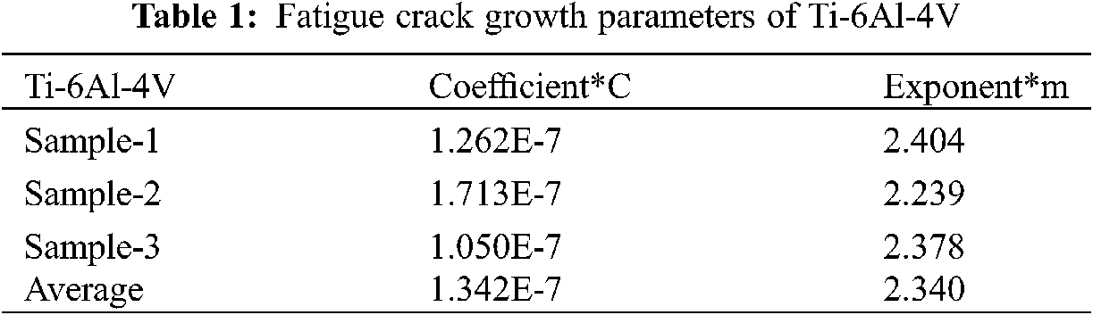
where a and N are propagation distance and number of load cycles, respectively. Then, ΔK is the range of stress intensity factor before and after crack propagation. Subsequently, C and n are material constants. Finally, the value in the similarity study is different. To increase the reliability of the study, we performed the fatigue crack growth rate experiment on Ti-6Al-4V, a frequently used material in implants. In this context, we adopted the three-point bending specimen made of Ti-6Al-4V to test the fatigue crack growth parameters. As shown in Fig. 1, the dimensions of the specimen were in accordance with the ASTM E647 Standard [19].
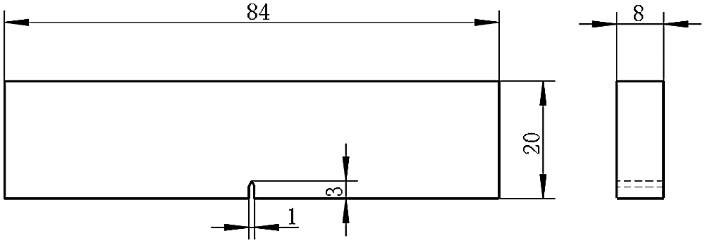
Figure 1: Three-point specimen with 3 mm in notch depth (unit: mm)
Fig. 2a illustrates that the experiment was executed on the BOSE-3510 electromagnetic fatigue testing machine. Then, Fig. 2b shows the clamping method of test, in which the specimen was symmetrically supported at the bottom, and the load was imposed on the middle, all of which were operated according to the ASTM Standard. Moreover, a sine wave type load with a frequency of 10 Hz was applied for the test. The maximum load applied to the specimen is 3.8 kN, and the stress ratio is R = 0.1. Then, the Olympus BX51 optical microscope was employed to measure the crack propagation distance on the sample, and Fig. 2c exemplifies the observation process.
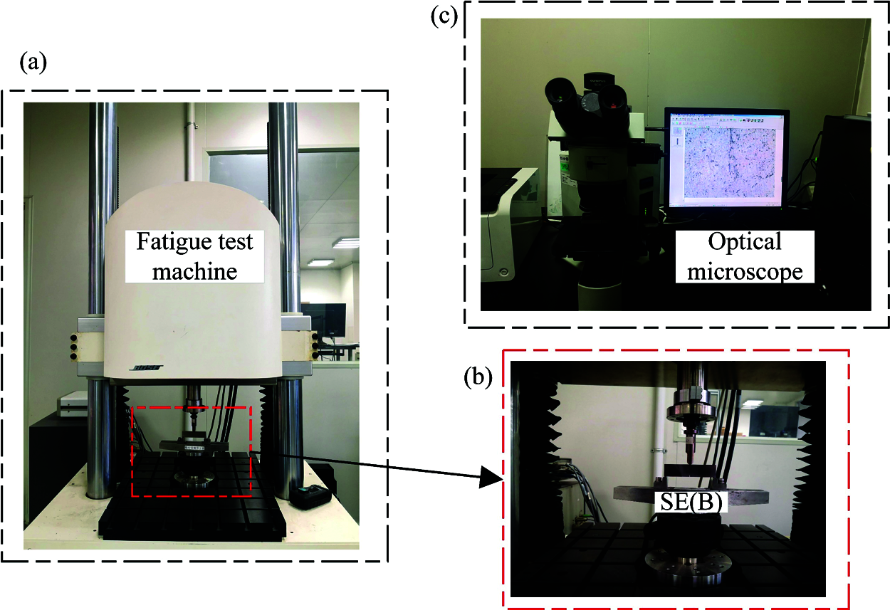
Figure 2: The process of fatigue crack growth rate experiment, (a) Fatigue test machine used for the experiment; (b) The load conditions and clam of three-point bending sample; (c) Optical microscope was used to measure the crack length of samples 1–3
We tested three samples at room temperature. Table 1 itemizes the findings after data processing. The average of the fatigue crack growth parameters of the three samples was adopted in the fatigue crack growth analysis of this study.
2.3 Numerical Models and Static Analysis
A three-dimensional internal fixation model consisting of the femur, bone plate, and several screws was established. Our previous research substantiated the feasibility of this simplified method [20]. As shown in Fig. 3a, the proximal and distal parts, and the femoral shaft were all replaced with simplified three-dimensional entities, in which the femoral shaft was substituted with a cylindrical solid model. Then, a 3 mm gap was created in the middle to simulate the transverse fracture of the femoral shaft. Based on Massin’s study and anatomical data, the physiological structural parameters of the femur are derived [21]. In order to improve the calculation efficiency, the thread in the hole of the bone plate was removed, and the screws were replaced with cylinders, as depicted in Fig. 3b. Each part was modeled in Solidworks and imported into ABAQUS for finite element pre-processing after assembly.
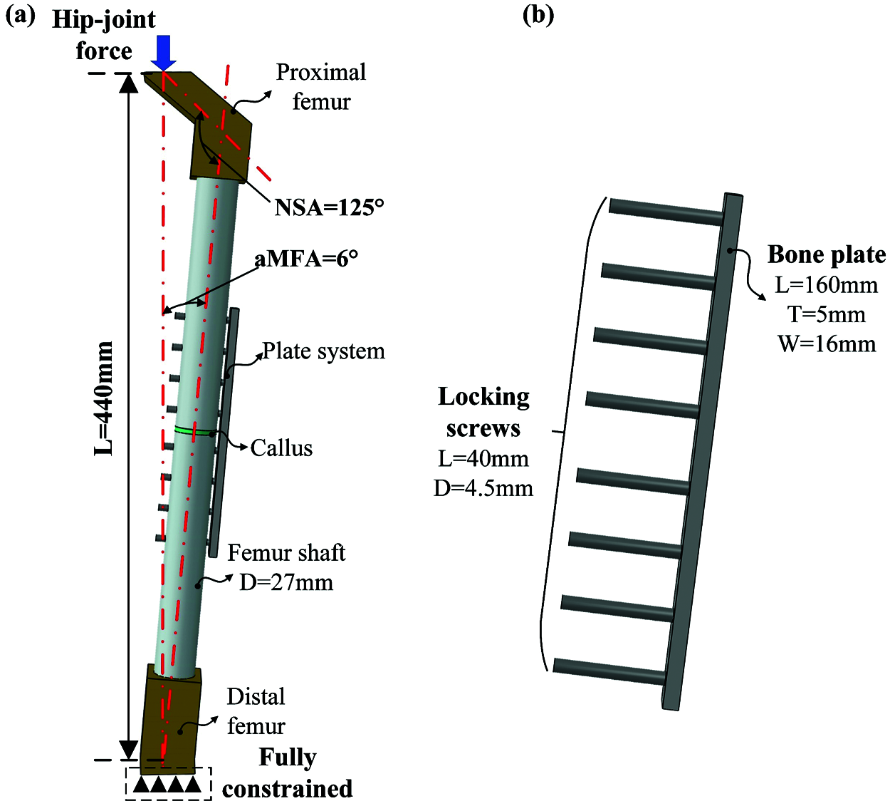
Figure 3: The internal fixation system model of femoral shaft fracture is used for numerical analysis, in which the femur is replaced by the cylindrical model, (a) Simplified model of bone plate fixation system; (b) Parameters of screws and bone plate (NSA: neck-shaft angle, aMFA: anatomical mechanical femoral angle, L: length, T: thickness, and W: width, D: diameter)
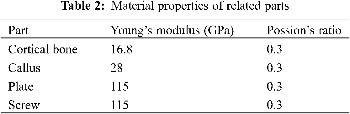
In this study, the “Tie” constraint in ABAQUS was used to simulate the contact relationship between bone-screws and bone-callus. Surface-to-surface contact was set to describe the contact interfaces between the plate and the screws, and the friction coefficient is 0.4. A hip-joint force of 1400 N was exerted toward the top of the femoral head to represent the stress of the femur while walking [22], whereas the bottom of the femur was completely constrained. As shown in Fig. 4a, the models of all parts were divided by hexahedral solid mesh through the partition operation in the software. Cortical bone material was given to all parts of the femoral, and Young’s modulus of the callus was taken during the eighth week of the fracture healing period [23]. Each part has a linear elastic homogeneous isotropic material [24], as presented in Table 2.
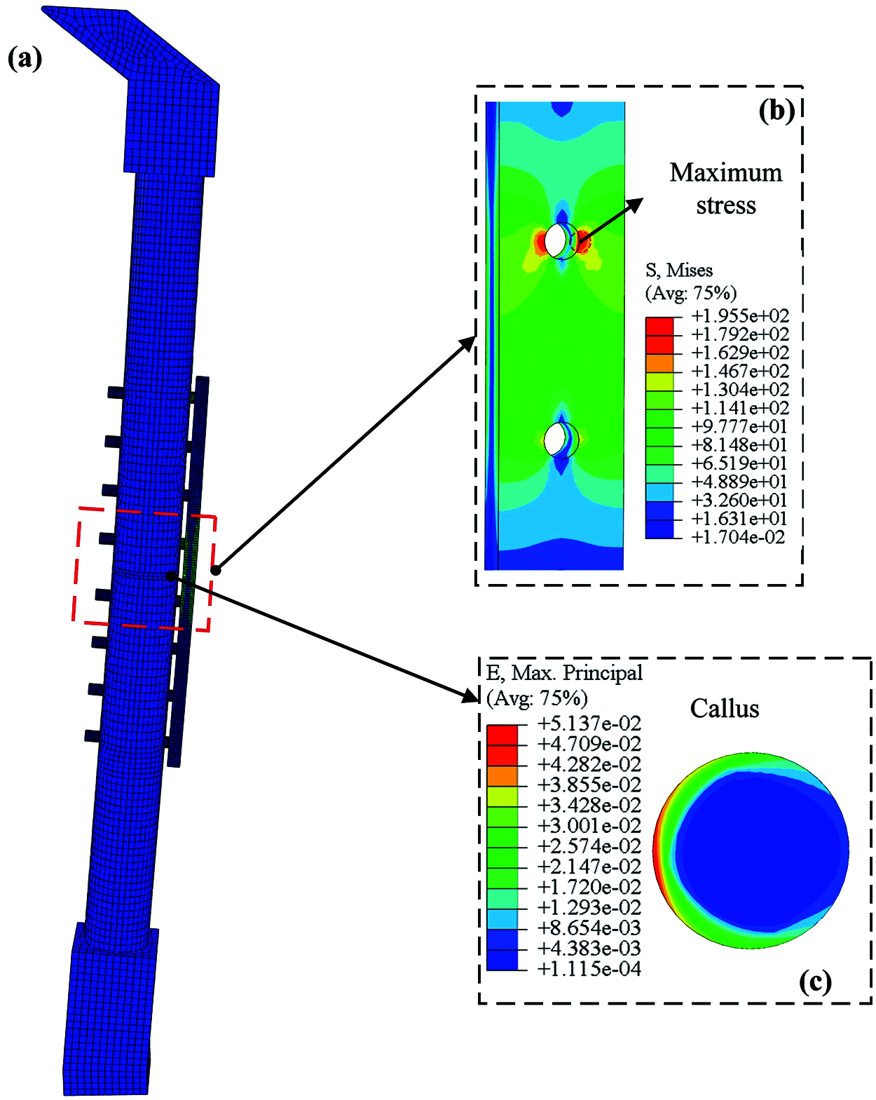
Figure 4: Static analysis results of internal fixation system model for femoral shaft fracture, (a) The grid and stress distribution of the bone plate fixation system; (b) The stress concentration on the plate is located at the edge of the screw hole; (c) The strain of bone callus under 1400 N load
To obtain the initial crack initiation position in the bone plate, the static load was applied to the mode. After the calculation in ABAQUS, the maximum stress on the bone plate and strain distribution on the callus are indicated in Figs. 4b and 4c, respectively.
2.4 Simulation of Fatigue Crack Growth and Insertion of CAH
The bone plate fixation model generated in ABAQUS was imported into Franc3D, and a quarter-circular crack with a radius of 0.5 mm was inserted at the point of maximum stress obtained by static analysis, as shown in Fig. 5a. Then, a cyclic load of 1400 N was applied to the model, and the ratio of the maximum stress to the minimum stress was established at 0.1.
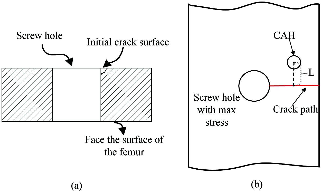
Figure 5: The insertion position of initial crack and the influence factors of CAH, (a) The shape and size of the crack in the cross-section of the bone plate; (b) The position and shape of the CAH
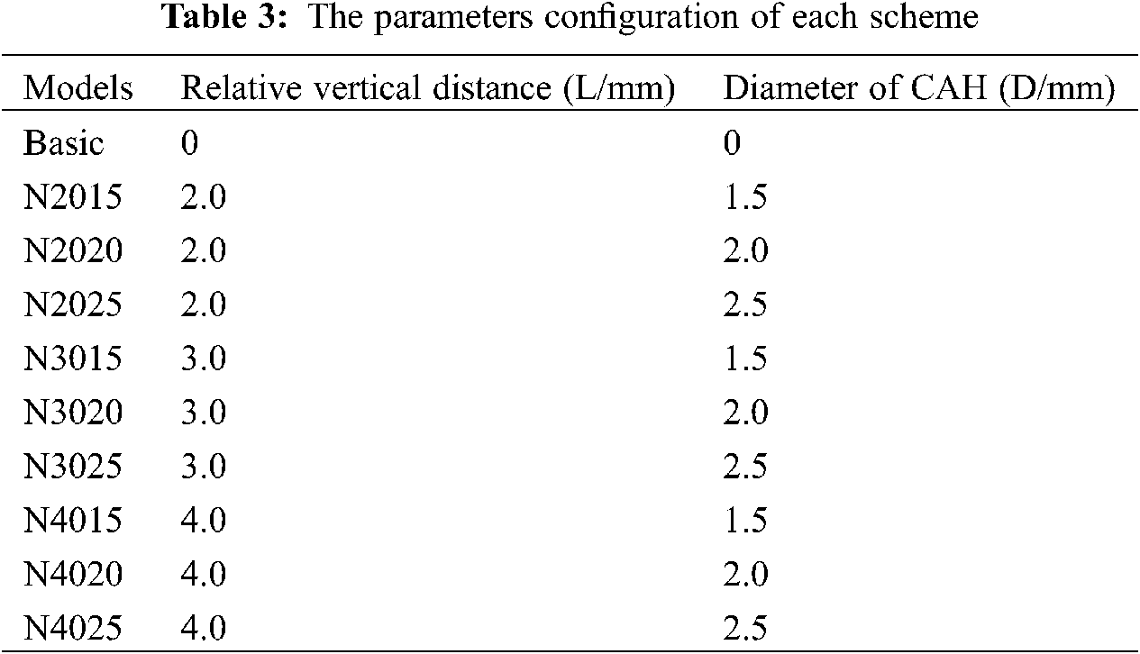
In this paper, the relative vertical distance (L) between CAH and crack path and the hole diameter (D) were the main influencing factors to be investigated. Fig. 5b illustrates the location of the CAH, where the center of the hole and the midpoint of the crack path (red line) were set and fixed on the same vertical line. We created a total of ten numerical models and set up a control group without CAH. Table 3 details the parameter configuration of each scheme. After inserting the crack, the stress intensity factor was calculated for each model, which was adopted to measure the ability of CAH to retard crack growth. To calculate the fatigue crack growth life, the Paris parameters of Ti-6Al-4V obtained from the experiment were encoded into the program. In addition, each model was subjected to static analysis before fatigue crack analysis to identify the influence of CAH on the biomechanics of the plate fixation system.
Through the co-simulation with ABAQUS, the stress intensity factor of the crack tip in the bone plate (without CAH) was calculated in Franc3D. Fig. 6 presents the value. It is evident that the SIF value of KI is significantly higher than the other two, and the latter can be ignored. Afterward, we extracted the crack propagation path and fracture surface in the plate, as shown in Figs. 7a and 7b, respectively.
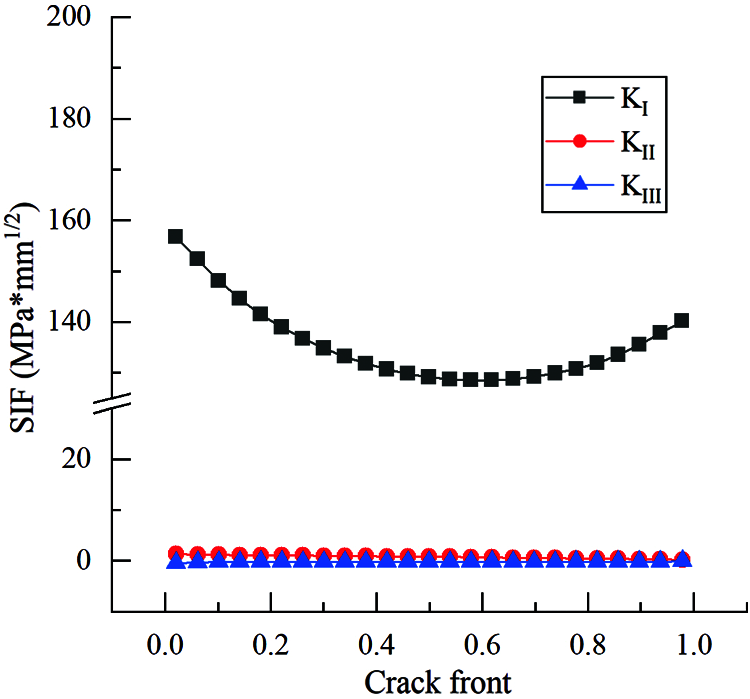
Figure 6: SIF distribution of bone plate without CAH, and the Type I SIF is the highest
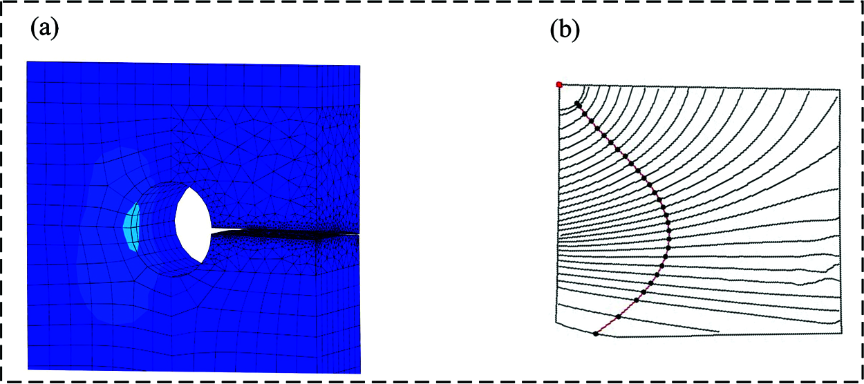
Figure 7: Fatigue crack propagation path of the bone plate obtained by numerical method, (a) Crack propagation path the bone plate; (b) The growth process of fracture surface in the bone plate
For the bone plate without CAH, the results indicated that the crack path on the plate surface is close to a straight line. From Fig. 7b, we found that the crack propagation distance at the outer edge of the bone plate is greater than the screw hole contact surface. The red curve in Fig. 7b represents the crack length obtained by polynomial fitting.
Based on the Paris parameters of Ti-6Al-4V generated from experiments, the fatigue propagation life of the crack in the bone plate was calculated in Figs. 8a–8c exhibit the influence of different CAH designs on the crack growth life of the plate, and the life within each scheme was improved except for N2025. In these figures, every point on the curve represents the propagation of the crack. Also, it can be clearly found that the propagation rate of the crack is substantially increased upon reaching the 16th step. Compared with the growth curve of the crack surface in Fig. 7b, the turning point of propagation rate corresponds to the position where the crack expands to the outer edge of the bone plate.
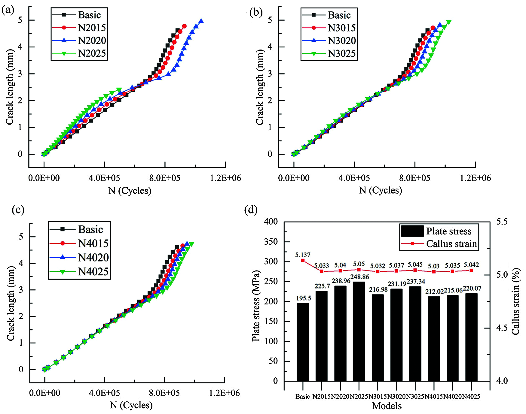
Figure 8: Effects of different CAH schemes on crack propagation life and biomechanics, (a–c) Number of cycles vs. crack length for the established model; (d) Effect of different CAH designs on the stress of plate and strain of callus
The increased amount of the crack propagation life of the bone plate represents the crack retardation capability of CAH. Looking at Figs. 8a–8c, for CAH at the same relative vertical distance, the fatigue life of the bone plate increases with the hole diameter. However, for the same CAH diameter, the increased amount of the fatigue life decreases with the increase of relative vertical distance. In particular, the bone plate crack in N2025 was successfully attracted to CAH, preventing the further propagation of the crack. Fig. 9 shows the influence of the relative vertical distance on the crack propagation path while maintaining the diameter of the CAH at 2 mm. Moreover, the observations suggest that the turning of the crack path is negatively associated with the relative vertical distance. Accordingly, it can be determined that CAH with a small relatively vertical distance and a larger diameter has a better retardation effect on the crack propagation of the bone plate.
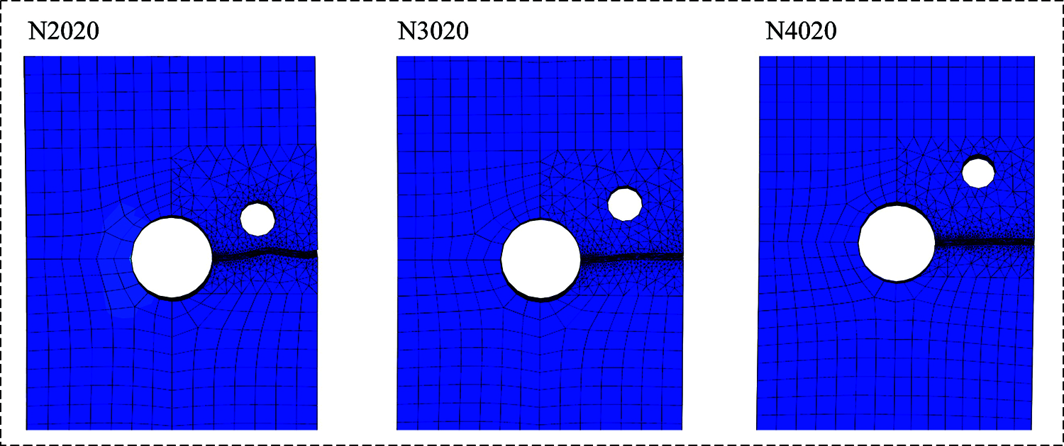
Figure 9: The effect of changing the relative vertical distance on the crack path
Before the crack was introduced into the model, the static analysis of the plate fixation system with different CAH designs was carried out, and Fig. 8d presents the results. The stress on the bone plate without CAH is the minimum at 195.50 MPa, while the stress in the N2025 model is the largest at 248.86 MPa. Compared with the fatigue life, the maximum stress on the bone plate is proportional to the diameter of the CAH and inversely proportional to the relative vertical distance. Collectively, these factors suggest that the insertion of CAH has a slight effect on the strain of the callus.
Generally, the bone plate applied to fix the damaged bone is kept in the body for several months [25] and is removed upon the healing of the bone. When the patient moves and bears weight, the bone plate bears the static stress and receives a relatively high cyclic load. More specifically, some patients necessitate long-term implantation of the bone plate due to compromised or impaired bone healing conditions. Thus, for an excellent fatigue performance, a bone plate is required. To reduce internal fixation failure, the primary goal of bone plate design should be prolonging fatigue life and ensuring a reasonable mechanical environment for bone healing.
It is recognized that the area of the maximum stress in the bone plate is most likely to be situated at the edge of the screw hole near the fracture line [26]. Along with this study, through the static analysis, existing literature determined that the initial crack is located at the stress concentration. Evidently, material defects around this hole must not be allowed during manufacturing to decrease the probability of fatigue crack initiation. For the bone plate without CAH, the same crack propagation path as the failed bone plate observed in the clinic was derived through simulation analysis [27].
Our findings demonstrate that the fatigue crack propagation path in the bone plate was almost a straight line on the plate surface, and the propagation rate of the crack tip was faster on the outer surface of the bone plate than the surface in contact with the screw hole. This propagation behavior is related to the distribution of stress intensity factors at the crack front in the bone plate. As presented in Fig. 6, the SIF of the KI type calculated in Franc3D is considerably higher than the other two types, implying that the crack propagation of the bone plate is predominantly an opening type. In contrast to the previous studies on the optimization of the bone plate to improve life, this paper began from the fatigue fracture mechanism of the bone plate. Then, it proposed a CAH method based on fracture mechanics to retard the growth of fatigue crack, thereby improving the durability of the bone plate.
Figs. 8 and 9 illustrate the deflected crack path in the bone plate with CAH. Moreover, the fatigue life of the bone plate has been significantly improved. By decreasing the relative vertical distance of CAH, the fatigue life of the bone plate is increased, while the opposite outcome occurs for the diameter of the CAH. In the model where the relative vertical distance and diameter of CAH are both 2 mm, the maximum improvement in fatigue life is observed. Besides, only the crack in the N2025 model was attracted to the placed holes. In this case, further crack propagation requires the generation of new micro-crack under cyclic loading, which will greatly enhance the fatigue life of the structure. In other words, drilling a crack attraction hole above the crack propagation path of the bone plate is effective for improving the fatigue life. However, it is worth noting that the maximum stress on the bone plate was increased by adding an extra hole.
Compared with the other models, the CAH with a relative vertical distance of 2 mm has distinctive effects on plate stress. The maximum stress we calculated is 248.86 MPa, showing an elevation of 53.36 MPa than the stress in the bone plate without CAH. Notably, even the maximum stress of the bone plate is significantly less the yield strength of Ti-6Al-4V at 800 MPa [28], which is acceptable in this study. Additionally, introducing CAH has a slight influence on the callus strain in the plate fixation system and can be ignored. Considering fatigue life and biomechanical factors, our results highlight that CAH with a relative vertical distance of 3 mm a diameter of 2 mm has excellent comprehensive performance.
Several limitations exist in this study. First, improving the calculation efficiency requires simplifying the model parameters and material properties of the femur, which may affect the bone strength and the stress value of the fixation system. Second, our study simplified the bone plate structure as a rectangle, which may slightly increase the crack propagation life of the bone plate. Third, the load applied to the femur only considered the hip-joint force in the direction of gravity. Although this loading method is commonly used in the biomechanical analysis of femoral fractures, it cannot fully simulate the force on the plate after the operation. Finally, the applicability of our findings to the optimal designing of the plate must be verified through various experiments.
This paper established a simplified model of the internal fixation system. Through static analysis, we determined that the initial crack was located at the edge of the screw hole closest to the fracture line in the bone plate. United simulation technique with ABAQUS and Franc3D was executed to predict the fatigue crack propagation path and life in the bone plate. Moreover, the crack in the bone plate presented a nearly straight path, and the propagation rate increased rapidly when the crack tip reached the edge of the bone plate. Furthermore, we compared the effects of different vertical distances and diameters of CAH on the crack propagation path and life in the bone plate. Our results indicate that the CAH with a small relative vertical distance and large diameter has an effective retarding effect on the fatigue crack growth life of the bone plate. Considering the impact of the introduction of CAH on the biomechanics of the bone plate fixation system, the findings suggest that CAH with a relative vertical distance of 3 mm is feasible to improve the fatigue life of the bone plate. Ultimately, this study can provide a new direction for the structural optimization of the bone plate. The result of the static analysis shows that the introduction of the crack attracting hole will change the stress distribution in the bone plate, and the occurrence of the initial cracks is related to the stress. Thus, the relationship between the initiation strength of crack and CAH needs further analysis. In the anti-fracture design of bone plates, the influence of numbers and relative position of CAH on crack propagation should be a new research target. In addition, we can propose a new type of bone plate with a unique structure and design to match the introduction of CAH. Future research should conduct fatigue experiments on artificial femurs, and the test results can provide new evidence for CAH analysis. For fracture patients who need long-term implantation, bone plates with crack attraction holes can be used to increase the service life of the implant.
Funding Statement: This work was supported by the Fundamental Research Funds for the Central Universities (KYCX20_0532, B200203153), and this grant was received by Zhonghang Zhao.
Conflicts of Interest: The authors declare that they have no conflicts of interest to report regarding the present study.
1. Sinha, S. K., Kumar, V., Singh, A. (2017). Outcomes of fracture shaft femur in pediatric population managed at emergency. Orthopaedics & Trauma, 8(4), 313–319. DOI 10.1016/j.jcot.2016.12.004. [Google Scholar] [CrossRef]
2. MacLeod, A. R., Pankaj, P. (2018). Pre-operative planning for fracture fixation using locking plates: Device configuration and other considerations. Injury-international Journal of the Care of the Injured, 49, S12–S18. DOI 10.1016/S0020-1383(18)30296-1. [Google Scholar] [CrossRef]
3. Vijayakumar, V., Marks, L., Bremmer-Smith, A., Hardy, J., Gardner, T. (2006). Load transmission through a healing tibial fracture. Clinical Biomechanics, 21(1), 49–53. DOI 10.1016/j.clinbiomech.2005.08.011. [Google Scholar] [CrossRef]
4. Kanchanomai, C., Phiphobmongkol, V., Muanjan, P. (2008). Fatigue failure of an orthopedic implant–A locking compression plate. Engineering Failure Analysis, 15(5), 521–530. DOI 10.1016/j.engfailanal.2007.04.001. [Google Scholar] [CrossRef]
5. Boyko, G., Mark, L. (2018). Why and how do locking plates fail? Injury–International Journal of the Care of the Injured, 49(S1), S56–S60. DOI 10.1016/S0020-1383(18)30305-X. [Google Scholar] [CrossRef]
6. Nassiri, M., Macdonald, B., O’Byrne, J. M. (2012). Locking compression plate breakage and fracture non-union: A finite element study of three patient-specific cases. European Journal of Orthopaedic Surgery & Traumatology, 22(4), 275–281. DOI 10.1007/s00590-011-0834-6. [Google Scholar] [CrossRef]
7. Tank, J. C., Schneider, P. S., Davis, E., Galpin, M., Gary, J. L. (2016). Early mechanical failures of the synthes variable angle locking distal femur plate. Journal of Orthopaedic Trauma, 30(1), e7–e11. DOI 10.1097/BOT.0000000000000391. [Google Scholar] [CrossRef]
8. Schneider, K., Oh, J. K., Zderic, I., Stoffel, K., Richards, R. G. et al. (2015). What is the underlying mechanism for the failure mode observed in the proximal femoral locking compression plate? A biomechanical study. Injury, 46(8), 1483–1490. DOI 10.1016/j.injury.2015.05.034. [Google Scholar] [CrossRef]
9. Gervais, B., Vadean, A., Brochu, M., Raison, M. (2018). Influence of the load modelling during gait on the stress distribution in a femoral implant. Multibody System Dynamics, 44(1), 93–105. DOI 10.1007/s11044-018-9621-z. [Google Scholar] [CrossRef]
10. Birringer, R. P., Ganot, G. S., James, B. A. (2016). Failure analysis of internal fixation medical devices: Overview and case studies. Journal of Failure Analysis and Prevention, 16(5), 849–857. DOI 10.1007/s11668-016-0159-1. [Google Scholar] [CrossRef]
11. Chen, G., Schmutz, B., Wullschleger, M., Pearcy, M. J., Schuetz, M. A. (2010). Computational investigations of mechanical failures of internal plate fixation. Proceedings of the Institution of Mechanical Engineers. Part H: Journal of Engineering in Medicine, 224(1), 119–126. DOI 10.1243/09544119JEIM670. [Google Scholar] [CrossRef]
12. Gervais, B., Brochu, M., Vadean, A., Raison, M. (2016). Failure analysis of a 316l stainless steel femoral orthopedic implant. Case Studies in Engineering Failure Analysis, 5–6, 30–38. DOI 10.1016/j.csefa.2015.12.001. [Google Scholar] [CrossRef]
13. Firoozabadi, R., McDonald, E., Nguyen, T. Q., Buckley, J. M., Kandemir, U. (2012). Does plugging unused combination screw holes improve the fatigue life of fixation with locking plates in comminuted supracondylar fractures of the femur? The Journal of Bone and Joint Surgery. British Volume, 94(2), 241–248. DOI 10.1302/0301-620X.94B2.27440. [Google Scholar] [CrossRef]
14. Oshkour, A. A., Davoodi, M. M., Abu, O., Yau, Y. H., Abas, W. (2013). Finite element analysis of circumferential crack behavior in cement–femoral prosthesis interface. Materials and Design, 49, 96–102. DOI 10.1016/j.matdes.2013.01.037. [Google Scholar] [CrossRef]
15. Ayatollahi, M. R., Razavi, S. M. J., Yahya, M. Y. (2015). Mixed mode fatigue crack initiation and growth in a CT specimen repaired by stop hole technique. Engineering Fracture Mechanics, 145, 115–127. DOI 10.1016/j.engfracmech.2015.03.027. [Google Scholar] [CrossRef]
16. Delkhosh, E., Khurshid, M., Barsoum, I., Barsoum, Z. (2020). Fracture mechanics and fatigue life assessment of box-shaped welded structures: FEM analysis and parametric design. Welding in the World, 64(9), 1535–1551. DOI 10.1007/s40194-020-00945-9. [Google Scholar] [CrossRef]
17. Liao, Y., Li, Y., Huang, M., Wang, B., Yang, Y. et al. (2019). Effect of hole relative size and position on crack deflection angle of repaired structure. Theoretical and Applied Fracture Mechanics, 101, 92–102. DOI 10.1016/j.tafmec.2019.02.010. [Google Scholar] [CrossRef]
18. Paris, P., Erdogan, F. (1963). A critical analysis of crack propagation laws. Journal of Fluids Engineering, 85(4), 528–533. DOI 10.1115/1.3656900. [Google Scholar] [CrossRef]
19. ASTM E 647-15e1. Standard test method for measurement of fatigue crack growth rates. ASTM International, West. Conshohocken, PA. 2015. https://www.astm.org. [Google Scholar]
20. Fang, R., Ji, A., Zhao, Z., Long, D., Chen, C. (2020). A regression orthogonal biomechanical analysis of internal fixation for femoral shaft fracture. Biocybernetics and Biomedical Engineering, 40(3), 1277–1290. DOI 10.1016/j.bbe.2020.07.006. [Google Scholar] [CrossRef]
21. Massin, P., Geais, L., Astoin, E., Simondi, M., Lavaste, F. (2000). The anatomic basis for the concept of lateralized femoral stems. Arthroplasty, 15(1), 93–101. DOI 10.1016/S0883-5403(00)91337-8. [Google Scholar] [CrossRef]
22. Mehboob, A., Chang, S. H. (2018). Biomechanical simulation of healing process of fractured femoral shaft applied by composite intramedullary nails according to fracture configuration. Composite Structures, 185, 81–93. DOI 10.1016/j.compstruct.2017.11.002. [Google Scholar] [CrossRef]
23. Sepehri, B., Taheri, E., Ganji, R. (2014). Biomechanical analysis of diversified screw arrangement on 11 holes locking compression plate considering time-varying properties of callus. Biocybernetics and Biomedical Engineering, 34(4), 220–229. DOI 10.1016/j.bbe.2014.05.001. [Google Scholar] [CrossRef]
24. Pendergast, M., Rusovici, R. (2015). A finite element parametric study of clavicle fixation plates. International Journal for Numerical Methods in Biomedical Engineering, 31(6), e02710. DOI 10.1002/cnm.2710. [Google Scholar] [CrossRef]
25. Izzawati, B., Daud, R., Rojan, A., Abdul Majid, M. S., Najwa, M. N. et al. (2019). The effect of bone healing condition on the stress of screw fixation in orthotropic femur bone for fracture stabilization. Materials Today: Proceedings, 16, 2160–2169. DOI 10.1016/j.matpr.2019.06.106. [Google Scholar] [CrossRef]
26. Uttam, K. K., Rajesh, K. B. (2020). Design and analysis of femoral locking plate under different loading conditions using suitable material. Materials Today: Proceedings, 21, 1128–1134. DOI 10.1016/j.matpr.2020.01.061. [Google Scholar] [CrossRef]
27. Thapa, N., Prayson, M., Goswami, T. (2015). A failure study of a locking compression plate implant. Case Studies in Engineering Failure Analysis, 3, 68–72. DOI 10.1016/j.csefa.2015.03.004. [Google Scholar] [CrossRef]
28. Fan, X., Chen, Z., Jin, Z., Zhang, Q., Zhang, X. et al. (2018). Parametric study of patient-specific femoral locking plates based on a combined musculoskeletal multibody dynamics and finite element modeling. Proceedings of the Institution of Mechanical Engineers, Part H: Journal of Engineering in Medicine, 232(2), 1–13. DOI 10.1177/0954411917745571. [Google Scholar] [CrossRef]
 | This work is licensed under a Creative Commons Attribution 4.0 International License, which permits unrestricted use, distribution, and reproduction in any medium, provided the original work is properly cited. |