

 | Molecular & Cellular Biomechanics |  |
DOI: 10.32604/mcb.2021.015605
ARTICLE
The Influence of Drag on Nonlinear Oscillatory Flow through Concentric Annulus
1Department of Mathematics, JSS Academy of Technical Education, Bangalore, India
2Department of Mathematics, Ramaiah Institute of Technology, Bangalore, India
*Corresponding Author: B. Umadevi. Email: bumadevi@jssateb.ac.in
Received: 30 December 2020; Accepted: 13 August 2021
Abstract: A mathematical model has been developed to study the effect of particle drag parameter and frequency parameter on velocity and pressure gradient in nonlinear oscillatory two phase flow. The main purpose is to apply the model to study the combined effect of introduction of the catheter and elastic properties of the arterial wall on the pulsatile nature of the blood flow. We model the artery as an isotropic thin walled elastic tube and the catheter as a coaxial flexible tube. Blood is modeled as an incompressible particulate viscous Newtonian fluid. Perturbation technique has been applied to find the approximations for velocity and pressure gradient up to second order. Numerical solutions are investigated with graphical presentations to understand the effects of drag parameter, frequency parameter and phase angle on velocity along radial direction and pressure gradient along axial directions. As the drag parameter increases, mean pressure gradient and mean velocity will be decreased. As frequency parameter increases mean velocity profile bends near the outer wall. Due to elastic nature of artery wall, a thin catheter experience small oscillations and a thick catheter remains stationary inside the artery. Finally, the effect of catheterization on various physiologically important flow rate characteristics—mean velocity, mean pressure gradient are studied for a range of different catheter sizes, particle drag parameter and frequency parameters.
Keywords: Particle drag; oscillatory flow; catheter
| Nomenclature | |
| (R,θ,Z): | Cylindrical coordinate system |
| | Velocity vector of the fluid phase |
| | Velocity vector of particulate phase |
| P: | Pressure |
| | Density of the fluid |
| | Time |
| | Number density of the particles |
| | Kinematic viscosity of the fluid |
| | stokes drag term |
| | Mass of the each drag particulate |
| | Non dimensional velocity of fluid phase |
| | Non dimensional velocity of particulate phase |
| | Diameter of the particulate |
| | Non-dimensional coordinates |
| | mean pressure |
| | characteristic wave speed |
| | Angular velocity |
| | Non-dimensional boundary radius |
| | Maximum radius |
| | Womersley number |
| | Phase lead angle |
| | Steady streaming Reynolds number |
| | Drag parameter |
| | Catheter Radius |
| | Mean axial velocity of first order |
| | Mean axial velocity of second order |
| | Mean Pressure gradient of second order |
| | Phase difference angle |
| | Radial directional length |
| Z: | Axial directional length |
| | Non dimensional flow rate |
Oscillatory flow is a widespread phenomenon and plays an important role in many fields, e.g. pneumatic propulsion, piston—driven flow, and acoustic oscillation are commonly used in mechanical engineering; pulsatile blood circulation, respiratory flow in lung, and capillary waves are of much interest in bio-mechanics; seasonal reversing wind, ocean circulations as well as tide flow are of high concern in meteorology, etc. More than mere oscillation or repetition, mass, momentum, and energy may be transferred via these reciprocating movements. Oscillatory flow of fluid enclosed in distensible vessels is of substantial significance due to its applications to various fields. The model can be used to understand (i) Blood flow in large arteries, (ii) wave propagation in fluid filled flexible tubes, which is essential for the study of acoustics or pulse propagation in arteries, (iii) flow in collapsible veins and (iv) peristaltic motion in the intestines. Many researchers for over 180 years are investigating the blood flow in arteries. Comparison of experimental measurements and mathematical modeling of these problems have been investigated. Recently, the study of flow with periodic variations has attracted much attention of researchers due to its various engineering and physiological applications. Oscillatory motion of a viscous liquid in a thin-walled elastic tube is investigated by Womersley [1]. Further, Womersley [2] studied the elastic tube theory of pulse conduction and oscillatory flow in mammalian arteries. Saffman [3] studied the stability of laminar flow of dusty gas. Rubinow et al. [4] analyzed the flow of a viscous fluid in an elastic tube with application to blood flow. RamachandraRao et al. [5] studied the pulsatile flow in tubes of various cross section. Taylor et al. [6] presented a mathematical model to analyze the blood flow through arteries and expressed the different pressure radius relationships for elastic tube. RamachandraRao [7] investigated the oscillatory flow in an elastic tube of variable cross section. Analytical solution by the method of linear approximation to describe the velocity distribution for laminar periodic flow through porous walls is proposed by Chang et al. [8]. Wang et al. [9] studied non-linear analysis of oscillatory flow with a non zero mean, in an elastic tube (artery). Srivastava [10] investigated the two phase model of blood flow through stenosed tubes in the presence of peripheral layer. Sarkar et al. [11] investigated the Correction to Flow Rate-Pressure Drop in Coronary Angioplasty: Steady Streaming Effect. Sarkar et al. [12] discussed the nonlinear analysis of oscillatory flow in the annulus of an elastic tube. In addition, they noticed that the velocity distribution in a small vessel depend significantly on geometry of the wall and its elastic nature. Jayaraman et al. [13] studied the Nonlinear analysis of arterial blood flow—steady streaming effect. Vajravelu et al. [14] considered the case of inserting a catheter into an elastic tube to observe the changes in blood flow pattern by taking Herschel–Bulkley fluid. Unsteady flow of a Jeffrey fluid in an elastic tube with a stenosis was considered by Sreedharamalle et al. [15]. Sochi [16] projected the expression for the volumetric flow as a function of pressure in elastic tube using two pressure area constitutive relationships. Sankar et al. [17] analyzed the cooling of heat sources by natural convection heat transfer in a vertical annulus, Siddiquiet al. [18] investigated mathematical analysis on pulsatile flow through a catheterized stenosedartery. Khudayarov et al. [19] investigated the mathematical simulation of nonlinear oscillations of viscoelastic pipelines conveying fluid. Do et al. [20] studied the Navier’s slip condition on time dependent Darcy—Forchheimer nano fluid using Spectral relaxation method. Tsimpoukis et al. [21] investigated the nonlinear oscillatory fully-developed rarefied gas flow in plane geometry. Kiran et al. [22] studied the Computational analysis of conjugate buoyant convective transport in an annulus. Naveed et al. [23] investigated the mathematical analysis of novel coronavirus (2019-nCov) delay pandemic model. Azam et al. [24] studied the numerical modeling and theoretical analysis of a nonlinear advection-reaction epidemic system. Saqib et al. [25] investigated the Symmetric MHD channel flow of nonlocal fractional model of BTF containing hybrid nanoparticles. Bilal et al. [26] investigated Finite element method about heat transfer analysis of Newtonian material in triangular cavity with square cylinder. Rasool et al. [27] studied the MHD squeezed Darcy-Forchheimer nano fluid flow between two h-distance apart horizontal plates. Lu et al. [28] studied the oscillatory two-phase flow in microchannels. Bilal et al. [29] studied the Analytical treatment of radiative Casson fluid over an isothermal inclined Riga surface with aspects of chemically reactive species.
Blood is a concentrated suspension of several formed cellular elements, red blood cells (RBCs or erythrocytes), white blood cells (WBCs or leukocytes) and platelets (thrombocytes), in an aqueous polymeric and ionic solution, the plasma, composed of 93% water and 3% particles, namely electrolytes, organic molecules, numerous proteins (albumin, globulins and fibrinogen) and waste products. Plasma’s central physiological function is to transport these dissolved substances, nutrients, wastes and the formed cellular elements throughout the circulatory system. The primary function of erythrocytes is to transport oxygen and carbon dioxide. Leukocytes are roughly spherical and much larger than erythrocytes, but they exist in a smaller number in blood. Leukocytes are subdivided into granulocytes (65%), lymphocytes (30%), monocytes (5%) and natural killer cells. Granulocytes are further subdivided into neutrophils (95%), eosinophils (4%) and basophils (1%). The leukocytes play a vital role in fighting infection and thus are able to migrate out of the blood vessels and into the tissues. Thrombocytes are small discoid non-nucleated cell fragments, much smaller than erythrocytes and leukocytes. Thrombocytes are a vital component of the blood clotting mechanism. The total volume concentration of leukocytes and thrombocytes is only about 1%. Blood cells are continually produced by the bone marrow over a human’s life.
In the present investigation Blood is modeled as an incompressible particulate viscous Newtonian fluid, and the flow will be fully developed. A mathematical model has been developed to view the oscillatory nonlinear flow in the annulus formed by catheterized artery. The analysis of the problem has been given by perturbation method. The variation of velocity and pressure observed with the influence of the parameters such as elastic parameter, Womersley number and drag parameter.
The artery modeled as an isotropic thin walled elastic tube with mean radius
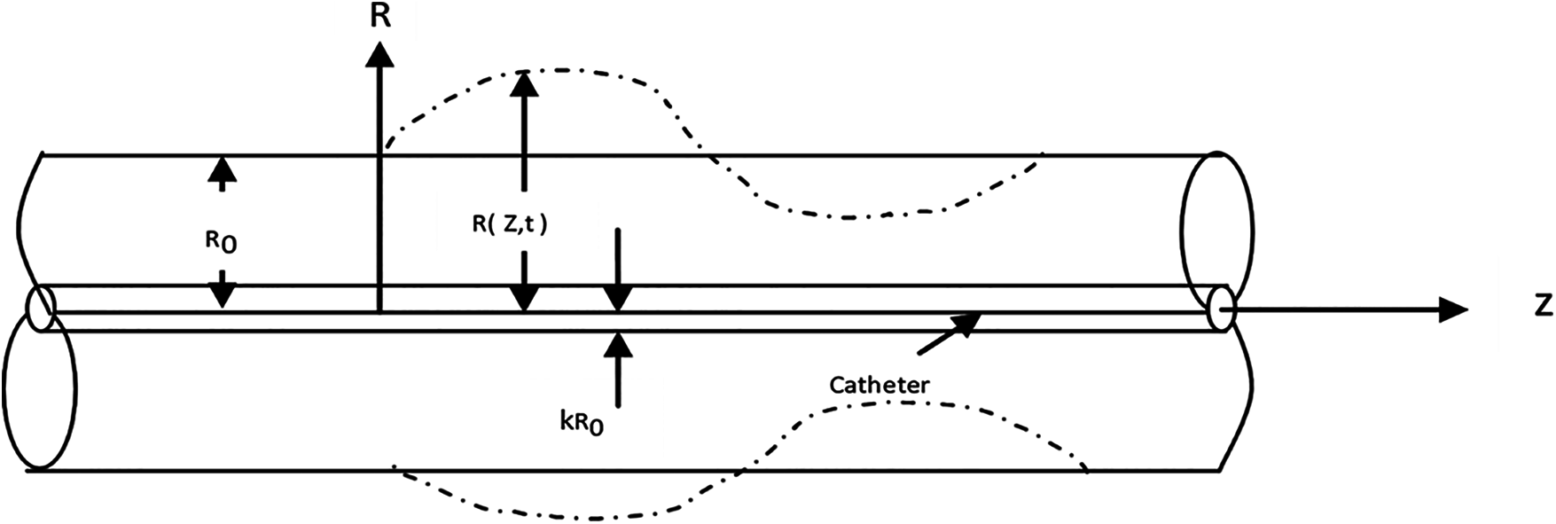
Figure 1: Physical configuration
Fig. 1 shows a schematic diagram of the annular geometry and the cylindrical coordinate system
where P is the pressure,
The radius of the tube
where Wc(t) represents the pulsatile movement of the flexible catheter.
Non-dimensional transformation variables given as follows:
where
Let us assume
In the Eq. (8) the axial viscous transport term
The boundary conditions are
Introducing the non dimensional transformation to overcome the difficulty of moving boundary as
Thus the equations of motion and continuity in the transformed coordinate are
where
The consequent boundary conditions are given by
The relation between the cross sectional area of the tube and the transmutable pressure difference—has to be specified to understand the flow in inert tubes. That is in the present problem, specifying
Being nonlinear in nature, the Eq. (14) does not provide the closed form solution. By using perturbation method, the approximate solutions for velocity and pressure distribution up to second order have been analyzed. The diameter variation in arteries, resulting from the effect of pressure pulse, represented by
where Re [ ] denotes the real part of a complex variable. Associated expressions can be written for
The equations corresponding to first order
The corresponding boundary conditions are
After solving for
The boundary conditions on radial velocity, i.e., Eq. (12), is
where
The ( `) denotes derivative with respect to
3.2 Steady Streaming Solution of O(ε2) for Arbitrary
The
where
A double over bar denotes time averaged solution.
Boundary conditions:
The solution for pressure and velocity are obtained as follows:
where
In the current study, the longitudinal oscillations of the catheter give rise to an additional term whose magnitude will depend upon
3.3 Dependence on Axial Position
where the constants of integration of
The flow rate of wave form is determined by the pressure wave, movement of the wall, and in a small measure by the movement of the catheter. The non dimensional form of the flow rate can be written as
where the first term is due to the catheter movement and the second is due to the oscillatory pressure gradient.
The present investigation reveals the influence of the particle drag parameter on nonlinear oscillatory flow through concentric annulus. The variation of velocity profile and pressure gradient have been analyzed with respect to the effects of drag parameter, frequency parameter and phase angle. In this section we discuss our results corresponding to values for the parameters in the model suitable to the physiological system. The frequency parameter
4.1 Mean Pressure Gradient and Velocity Distribution
The induced mean pressure gradient
Variations of mean axial velocity
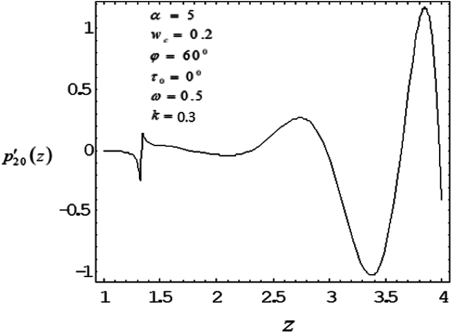
Figure 2: Variation of mean pressure gradient along the axial length with drag parameter 0.5
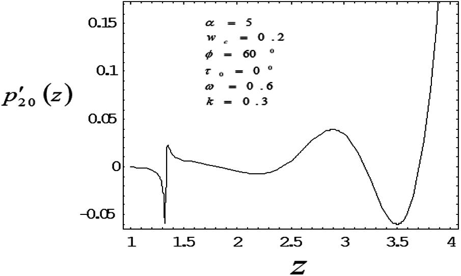
Figure 3: Variation of mean pressure gradient along the axial length with drag parameter 0.6
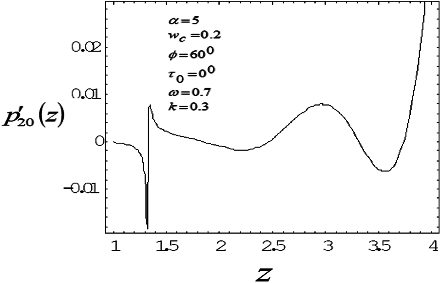
Figure 4: Variation of mean pressure gradient along the axial length with drag parameter 0.7
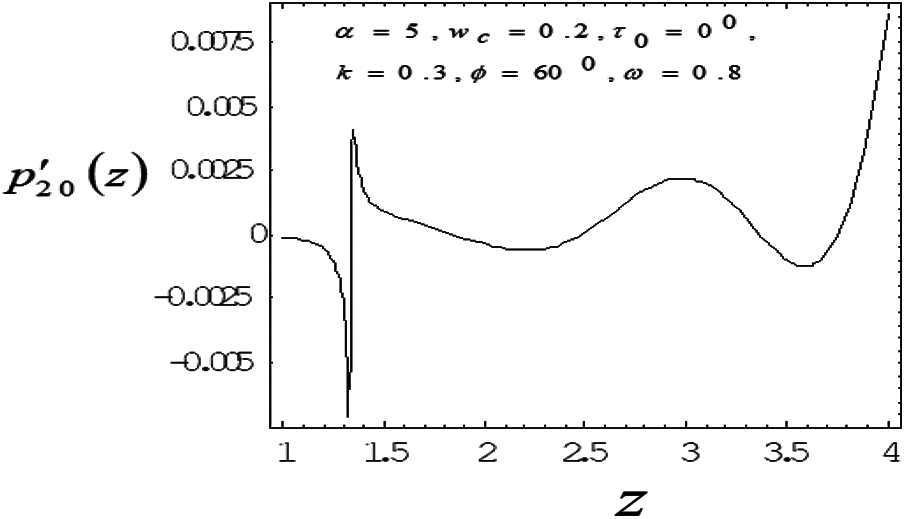
Figure 5: Variation of mean pressure gradient along the axial length with drag parameter 0.8
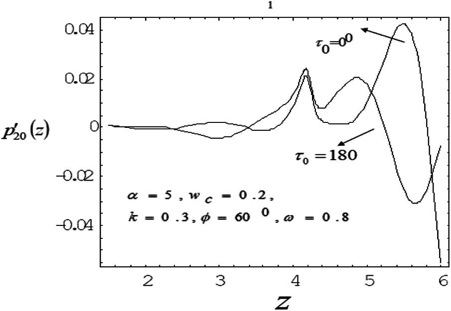
Figure 6: Variation of mean pressure gradient along the axial length for different phase lead angles
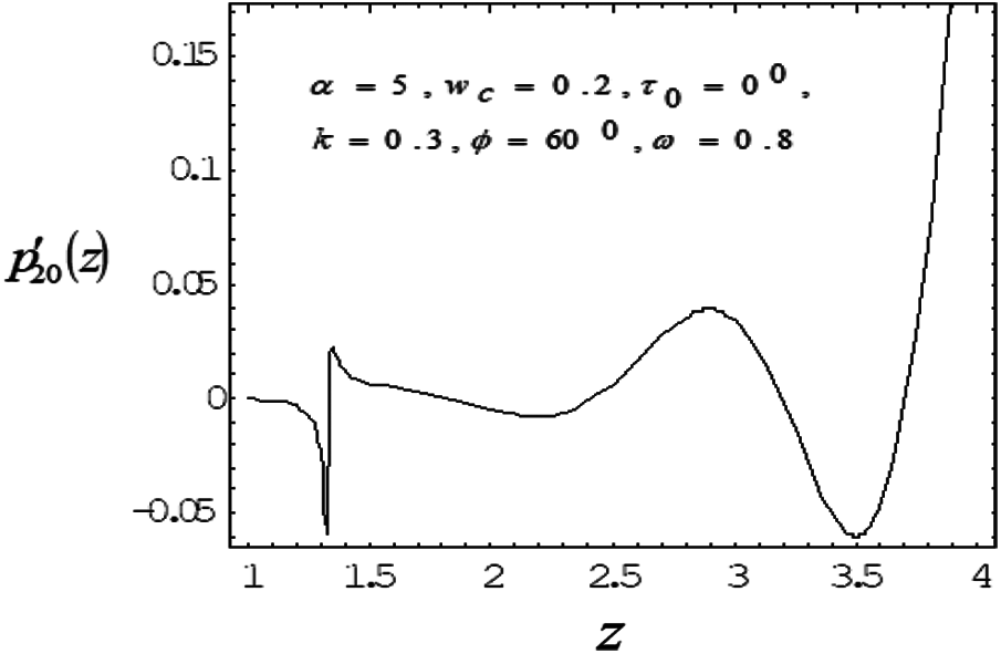
Figure 7: Variation of mean pressure gradient along the axial length with Catheter radius 0.3
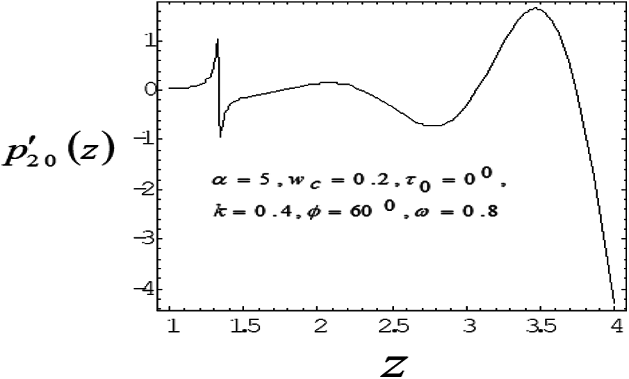
Figure 8: Variation of mean pressure gradient along the axial length with Catheter radius 0.4
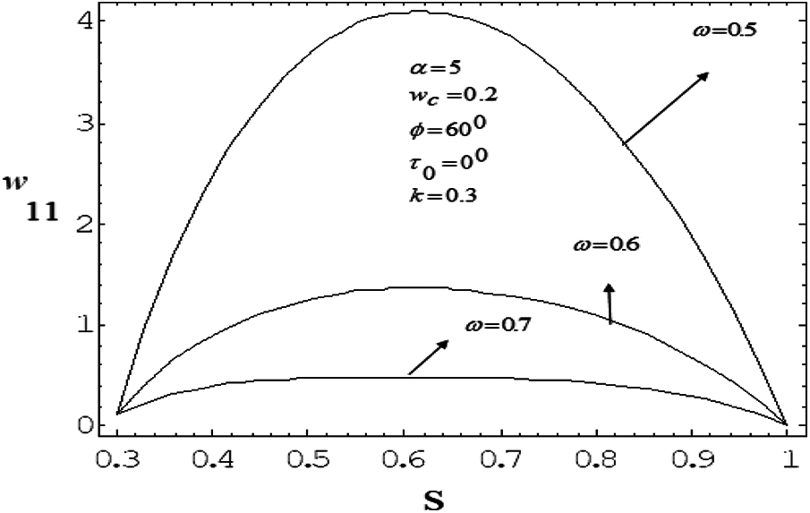
Figure 9: Variation of mean axial velocity of first order along the radial direction for various values of drag parameter with frequency parameter value 5
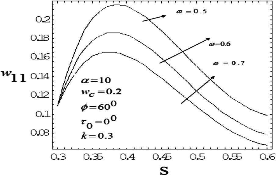
Figure 10: Variation of mean axial velocity of first order along the radial-direction for various vales of drag parameter with frequency parameter value 10
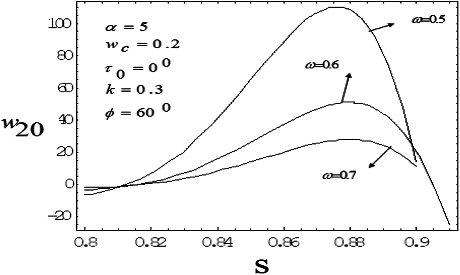
Figure 11: Variation of mean axial velocity of second order along the radial-direction for various vales of drag parameter with frequency parameter value 5
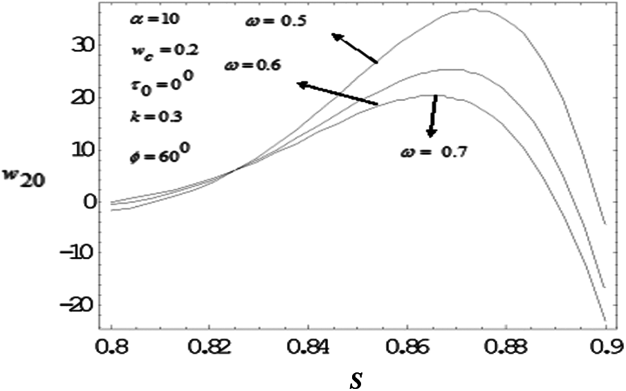
Figure 12: Variation of mean axial velocity of second order along the radial-direction for various vales of drag parameter with frequency parameter value 10
To study the nonlinear oscillatory flow in the concentric annulus with the influence of particle drag and frequency parameter, a mathematical model has been developed. The model has been applied to investigate induced mean pressure gradient, mean velocity distribution—vary noticeably along axial, radial correspondingly. The computational results were found in good agreement with the bench mark results. As particle drag parameter increases then mean pressure gradient and mean velocity distribution decreases. Mean velocity profile bends near the outer wall (artery wall) of the tube, as frequency parameter increases, suggesting the influence of the elastic nature of the tube wall on the flow. Also depending on catheter size, a slim catheter experience the minute oscillations due to the flow conditions is likely to influence in the same way as thicker catheter which remains quite stationary inside the artery.
This study gives an insight to enormous applications in the field of diagnosing, treating and certain surgical procedures related to the disorders/diseases which originate in the body relating to COVID-19 symptoms, cardiovascular, pulmonary, synovial systems etc., where as the different types of cardiovascular diseases include Aneurysms, Angina, Atherosclerosis, Stroke, different types of cerebrovascular disease, Heart Failure, Coronary Heart diseases and Myocardial infarction or Heart attacks.
Acknowledgement: The authors acknowledge the support of JSS Academy of Technical Education, Bangalore and Ramaiah Institute of Technology, Bangalore.
Funding Statement: The authors received no specific funding for this study.
Conflicts of Interest: The authors declare that they have no conflicts of interest to report regarding the present study.
1. Womersely, J. R. (1955). Oscillatory motion of a viscous liquid in a thin-walled elastic tube-I: The linear approximation of long waves. Philosophical Magazine Series, 46(373), 199–221. DOI 10.1080/14786440208520564. [Google Scholar] [CrossRef]
2. Womersely, J. R. (1957). An elastic tube theory of pulse transmission and oscillatory flow in mammalian arteries, WADCTR-56-614. Ohio: Wright Air Development Center, Wright Patterson Air Force Base. [Google Scholar]
3. Saffman, P. G. (1962). On the stability of laminar flow of dusty gas. Journal of Fluid Mechanics, 120(13), 120–128. DOI 10.1017/S0022112062000555. [Google Scholar] [CrossRef]
4. Rubinow, S. I., Keller, J. B. (1972). Flow of a viscous fluid through an elastic tube with applications to blood flow. Journal of Theoretical Biology, 35(2), 299–313. DOI 10.1016/0022-5193(72)90041-0. [Google Scholar] [CrossRef]
5. Rao, A. R., Devanathan, R. (1973). Pulsatile flow in tubes of varying cross-section. Journal of Aplied Mathematics and Physics, 24(2), 203–213. [Google Scholar]
6. Taylor, L. A., Gerrard, J. H. (1977). Pressure-radius relationships for elastic tubes and their application to arteries. Part 1—Theoretical relationships. Medical and Biological Engineering and Computing, 15(5), 11–17. DOI 10.1007/BF02441569. [Google Scholar] [CrossRef]
7. RamachandraRao, A. (1983). Oscillatory flow in an elastic tube of variable cross-section. ActaMechanica, 46, 155–165. [Google Scholar]
8. Chang, H. C., Ha, S. C., Park, J. K., Kim, I. H., Shin, H. D. (1989). Velocity field of pulsatile flow in a porous tube. Journal of Biomechanics, 22(11-12), 1257–1262. DOI 10.1016/0021-9290(89)90228-5. [Google Scholar] [CrossRef]
9. Wang, D. M., Tarbell, J. M. (1995). Non-linear analysis of oscillatory flow with a non zero mean, in an elastictube(artery). Journal of Biomechanical of Engineering, 117(1), 127–135. DOI 10.1115/1.2792260. [Google Scholar] [CrossRef]
10. Srivastava, V. P. (1996). Two phase model of blood flow through stenosed tubes in the presence of peripheral layer. Journal of Biomechanics, 1377(29), 1377–1382. DOI 10.1016/0021-9290(96)00037-1. [Google Scholar] [CrossRef]
11. Sarkar, A., Jayaraman, G. (1998). Correction to flow rate-pressure drop in coronary angioplasty: Steady streaming effect. Journal of Biomechanics, 31(9), 781–791. DOI 10.1016/S0021-9290(98)00053-0. [Google Scholar] [CrossRef]
12. Sarkar, A., Jayaraman, G. (2001). Nonlinear analysis of oscillatory flow of in the annulus of an elastic tube: Application to catheterized artery. Physics of the Fluids, 13(10), 2901–2911. DOI 10.1063/1.1389285. [Google Scholar] [CrossRef]
13. Jayaraman, G., Sarkar, A. (2005). Nonlinear analysis of arterial blood flow—Steady streaming effect. Nonlinear Analysis: Theory, Methods & Applications, 63(5–7), 880–890. DOI 10.1016/j.na.2005.01.016. [Google Scholar] [CrossRef]
14. Vajravelu, K., Sreenadh, S., Devaki, P., Prasad, K. V. (2011). Mathematical model for a Herschel-Bulkley fluid flow in an elastic tube. Central European Journal of Physics, 9, 1357–1365. [Google Scholar]
15. Sreedharamalle, S., Palluru, D., Diwakar Reddy, D., Krishnaiah (2012). Unsteady flow of a Jeffrey fluid in an elastic tube with a stenosis. International Conference of Fluid dynamics and Thermodynamics Technologies, vol. 33. Singapore, IPCSIT. [Google Scholar]
16. Sochi, T. (2014). The flow of Newtonian and power-law fluids in elastic tubes. International Journal of Non-Linear Mechanics, 67(6), 245–250. DOI 10.1016/j.ijnonlinmec.2014.09.013. [Google Scholar] [CrossRef]
17. Sankar, M., Do, Y., Ryu, S., Jang, B. (2015). Cooling of heat sources by natural convection heat transfer in a vertical annulus. An International Journal Computation and Methodology, 68(6), 847–869. DOI 10.1080/10407782.2015.1023097. [Google Scholar] [CrossRef]
18. Siddiqui, S. U., Awasthi, C. (2017). Mathematical analysis on pulsatile flow through a catheterized stenosed artery. Journal of Applied Mathematical Physics, 5(9), 1874–1886. DOI 10.4236/jamp.2017.59157. [Google Scholar] [CrossRef]
19. Khudayarov, B. A., Turaev, F. Z. (2019). Mathematical simultion of nonlinear oscillations of viscoelastic pipelines conveying fluid. Applied Mathematical Modelling, 66, 662–679. DOI 10.1016/j.apm.2018.10.008. [Google Scholar] [CrossRef]
20. Do, Y., Ramesh., G. K., Roopa, G. S., Sankar, M. (2019). Navier’s slip condition on time dependent Darcy-Forchheimer nano fluid using spectral relaxation method. Journal of South Central University, 26(7), 2000–2010. DOI 10.1007/s11771-019-4147-y. [Google Scholar] [CrossRef]
21. Tsimpoukis, A., Vasileiadis, N., Tatsios, G., Valougeorgis, D. (2019). Nonlinear oscillatory fully-developed rarefied gas flow in plane geometry. Physics of Fluids, 31(6), 06108. DOI 10.1063/1.5099051. [Google Scholar] [CrossRef]
22. Kiran, S., Keerthi, R., Sankar, M., Do, Y. (2020). Computational analysis of conjugate buoyant convective transport in an annulus. Advances in Fluid Mechanics, 26, 889–905. [Google Scholar]
23. Naveed, M., Rafiq, M., Raza, A., Ahmed, N., Khan, I. et al. (2020). Mathematical analysis of novel coronavirus (2019-nCov) delay pandemic model. Computers, Materials & Continua, 64(3), 1401–1414. DOI 10.32604/cmc.2020.011314. [Google Scholar] [CrossRef]
24. Azam, S., Macius-Diaz, J. E., Ahmed, N., Khan, I., Iqbal, M. S. et al. (2020). Numerical modeling and theoretical analysis of a nonlinear advection-reaction epidemic system. Computer Methods and Programs in Biomedicine, 193(772), 105429. DOI 10.1016/j.cmpb.2020.105429. [Google Scholar] [CrossRef]
25. Saqib, M., Shafie, S., Khan, I., Chu, Y. M., Nisar, K. S. (2020). Symmetric MHD channel flow of nonlocal fractional model of BTF containing hybrid nanoparticles. Symmetry, 663(12), 12040663. DOI 10.3390/sym12040663. [Google Scholar] [CrossRef]
26. Bilal, S., Mahmood, R., Majeed, A. H., Khan, I., Nisar, K. S. (2020). Finite element method about heat transfer analysis of Newtonian material in triangular cavity with square cylinder. Journal of Materials Research and Technology, 9(3), 4904–4918. DOI 10.1016/j.jmrt.2020.03.010. [Google Scholar] [CrossRef]
27. Rasool, G., Khan, W. A., Bilal, S. M., Khan, I. (2020). MHD squeezed Darcy-Forchheimer nanofluid flow between two h-distance apart horizontal plates. Open Physics, 18(1), 1100–1107. DOI 10.1515/phys-2020-0191. [Google Scholar] [CrossRef]
28. Lu, Z., Dupuis, E. D., Patel, V. K., Momen, A. M., Shahab, S. (2021). Ultrasonic oscillatory two-phase flow in microchannels. Physics of Fluids, 33(3), 032003. DOI 10.1063/5.0039971. [Google Scholar] [CrossRef]
29. Bilal, S., Asogwa, K., Alotaibi, H., Malik, M. Y., Khan, I. (2021). Analytical treatment of radiative Casson fluid over an isothermal inclined Riga surface with aspects of chemically reactive species. Alexandria Engineering Journal, 60(5), 4243–4253. DOI 10.1016/j.aej.2021.03.015. [Google Scholar] [CrossRef]
Appendix
where
 | This work is licensed under a Creative Commons Attribution 4.0 International License, which permits unrestricted use, distribution, and reproduction in any medium, provided the original work is properly cited. |