Materials
| Journal of Renewable Materials |
DOI: 10.32604/jrm.2021.015166
ARTICLE
Characterization of the Flexural Behavior of Bamboo Beams
1School of Civil Engineering, Shaanxi Key Laboratory of Structure and Earthquake Resistance, Xi’an University of Architecture and Technology, Xi’an, 710055, China
2The Key Laboratory of Plateau Building and Eco-Community in Qinghai, Qinghai Building and Materials Research Co., Ltd., Xining, 810008, China
3Anhui Province Key Laboratory of Green Building and Assembly Construction, Anhui Institute of Building Research & Design, Hefei, 230031, China
*Corresponding Author: Jiping Hao. Email: haojiping@xauat.edu.cn
Received: 27 November 2020; Accepted: 19 February 2021
Abstract: Bamboo is a renewable and environmentally friendly material often used for construction. This study investigates the flexural behavior of bamboo beams through theoretical and finite element (FE) analyses. Considering the material’s nonlinearity, a method of calculating load-deflection curves is proposed and validated via FE analysis. The interfacial slippage dominated by the shear stiffness of the interface between two bamboo poles significantly influences the flexural behavior of double-pole bamboo beams. Thus, the load-deflection curves for different shear stiffnesses can be obtained via theoretical and FE analyses. Subsequently, a novel configuration using diagonal steel bands to avoid slippage is presented. An inclination angle of 45° is suggested to adequately develop the stiffness and bearing capacity of the steel band.
Keywords: Bamboo beam; flexural behavior; interfacial slippage; steel band; FE analysis
Bamboo is a sustainable material used in the construction of buildings [1,2]. It is renewable and environmentally friendly. Its growth speed and strength are greater than those of timber. Bamboo is a typical anisotropic material. García et al. [3] and Akinbade et al. [4] studied the transverse properties of bamboo, testing the elastic constants and tensile capacity in the transverse direction. The longitudinal properties of bamboo were also investigated. Liu et al. [5] measured the longitudinal tensile strength and elastic modulus. Qiu et al. [6] constructed a longitudinal constitutive model using the Ramberg–Osgood relation. These studies indicated that the tensile strength of bamboo in the longitudinal direction was close to the strength of steel while the elastic modulus of bamboo was approximately one-twentieth of that of steel. Hence, bamboo is considered suitable for use as a centrally stressed member [7–12]. As one of the most important members of a structure, understanding the flexural behavior of bamboo beams is extremely important to increase their application in construction [2,13]. Currently, two types of bamboo beams have been widely studied: Original and engineered bamboo beams.
For original bamboo beams, the natural shape of the bamboo is maintained; this advantage can be exploited in structures. García-Aladín et al. [14,15] conducted bending tests on single and double bamboo poles to calculate their shear moduli and stiffnesses. Trujillo et al. [16] implemented more than 200 bending tests on bamboo poles, which were used for bamboo strength grading. Nurmadina et al. [17] adopted three-point bending tests to obtain the bending stiffness of a single bamboo pole. Lorenzo et al. [18] proposed an analytical bimodulus model to determine the strain and stress distribution of a single bamboo beam. These studies indicated that owing to the deflection limit, it was difficult to achieve large spans using a single bamboo pole as a beam [19,20]. Considering the superiority of original bamboo, a bionic bamboo beam, including tubes and diaphragms, was invented [21,22]. Its bending model was deduced using Euler-Bernoulli beam theory.
To increase the applicability of original bamboo beams, Tian et al. [23] presented a composite mortar-sprayed bamboo beam. The results demonstrated that interfacial slippage between two bamboo poles was difficult to avoid and the composite effect could not be fully exploited. Therefore, bolted connections are commonly applied to avoid interfacial slip [24–28]. Conversely, the engineered bamboo beam is a new bamboo product, the section of which can be varied and the bending stiffness can be determined according to the design requirement [29,30]. Huang et al. [31] and Li et al. [32] analyzed the flexural behavior of engineered bamboo beams and their ultimate bearing capacity and deformation were deduced. Furthermore, engineered bamboo can be effectively combined with other materials (i.e., steel, concrete, and timber) to form new composite bamboo beams. Wei et al. [33] and Wang et al. [34] proposed a fiber-reinforced engineered bamboo beam and a bamboo-concrete composite beam, respectively. Zhong et al. [35] and Wei et al. [36] adopted steel bars to enhance the engineered bamboo beam. Li et al. [37] presented an I-section bamboo-steel composite beam. However, producing engineered bamboo is energy consuming and the process is not environmentally friendly.
To completely exploit the excellent performance of original bamboo beams, this study investigated the flexural behavior of single-pole and double-pole bamboo beams via theoretical analysis. Simultaneously, the influence of interfacial slippage was analyzed. Then, an effective configuration to avoid slippage without destroying the original bamboo was proposed and validated.
2.1 Constitutive Model Along the Grain
The flexural behavior of bamboo beams is directly related to the constitutive model of bamboo along the grain, as shown in Fig. 1 and Eq. (1).

Figure 1: The constitutive model of bamboo along the grain
2.2 Curvature of a Single-Pole Bamboo Beam
Fig. 2 presents the stress and strain distributions in the elastic stage for a single-pole bamboo beam, conforming to the plane-section assumption. Owing to the greater elastic modulus in the tensile zone, the neutral axis is below the midline of the beam. The cross-section of bamboo is assumed to be an ideal annulus with invariable thickness. A polar coordinate system is established such that the origin of the coordinate system is located at the center of the section and the lower part of the vertical symmetry axis is used as the polar axis.

Figure 2: Stress and strain distributions during the elastic stage
The strain and stress on the central line of the annulus are adopted to represent the strain and stress at the same polar angle. Thus, the area integral can be simplified as the arc integral in the following deduction. Eq. (2) expresses the stress distribution along the central line of the annulus, where the stress is a function of the polar angle.
where
where
When the polar angle
where
where
Fig. 3 shows the stress and strain distributions during the elastic-plastic stage. The cross-section of bamboo comprises three areas: Elastic tension, elastic compression, and plastic compression. Two dividing lines, corresponding to angles

Figure 3: Stress and strain distributions during the elastic-plastic stage
Eq. (15) expresses the stress distribution during the elastic-plastic stage, which comprises three parts.
Considering the deformation relationship over the section yields:
where
The bending moment of the section is expressed as
where the constant coefficient
where
2.3 Curvature of a Double-Pole Bamboo Beam
There are also two curvature stages for a double-pole bamboo beam. Owing to the cross-section containing two annuli, the elastic stage can be considered for two cases and the elastic-plastic stage for four. Two polar coordinate systems are separately established for the top and bottom bamboo poles.
The location of the neutral axis differentiates the two cases. The neutral axis is located between the centerlines of the two annuli in Case 1; the neutral axis in Case 2 intersects the centerline of the bottom bamboo pole.
(1) Case 1:
Fig. 4 shows the stress and strain distributions in Case 1.

Figure 4: Stress and strain distributions in Case 1
Eqs. (28)–(32) express the curvature analysis of a double-pole bamboo beam in Case 1.
(2) Case 2
Fig. 5 shows the stress and strain distributions in Case 2.

Figure 5: Stress and strain distributions in Case 2
Eqs. (33)–(37) express the curvature analysis of a double-pole bamboo beam in Case 2.
The neutral axis and boundary of the elastic and plastic areas differentiate the four cases.
(1) Case 3
Fig. 6 shows the stress and strain distributions in Case 3.

Figure 6: Stress and strain distributions in Case 3
Eqs. (38)–(43) express the curvature analysis of a double-pole bamboo beam in Case 3.
(2) Case 4
Fig. 7 displays the stress and strain distributions in Case 4.

Figure 7: Stress and strain distributions in Case 4
Eqs. (44)–(49) express the curvature analysis of a double-pole bamboo beam in Case 4.
(3) Case 5
Fig. 8 illustrates the stress and strain distributions in Case 5.

Figure 8: Stress and strain distributions in Case 5
Eqs. (50)–(55) express the curvature analysis of a double-pole bamboo beam in Case 5.
(4) Case 6
Fig. 9 shows the stress and strain distributions in Case 6.

Figure 9: Stress and strain distributions in Case 6
Eqs. (56)–(61) express the curvature analysis of a double-pole bamboo beam in Case 6.
For a simply supported beam, the bending moment is easily plotted. Fig. 10a shows the bending moment diagram under an external load
where

Figure 10: Bending moment diagram of external loads and unit load. (a) External load and (b) Unit load
Fig. 11 shows the calculation process of the load-deflection curves. There are three steps in the calculation. For a single-pole bamboo beam, 1) The maximum bending moment of the elastic stage
The elastic stage of a double-pole bamboo beam can be considered for two cases and the elastic-plastic stage for four. For this reason, the first two steps for a double-pole bamboo beam are more complicated. However, the load-deflection curve calculations are the same as for a single-pole bamboo beam. The critical bending moment

Figure 11: Calculation process of load-deflection curves. (a) Single-pole bamboo beam and (b) Double-pole bamboo beam
2.5 Influence of Interfacial Slippage
The interfacial slippage between two bamboo poles is difficult to avoid; this has not been previously considered in double-pole bamboo beam analyses. The influence of interfacial slippage is analyzed based on the following assumptions: 1) The bamboo materials are linearly elastic. 2) The shear force at the interface is proportional to the slippage. 3) The curvatures and deflections of the two bamboo poles are consistent. 4) The shear deformation is not considered when the plane-section assumption is satisfied.
Fig. 12 shows an interfacial slippage diagram. The equilibrium differential equation, based on a tiny segment, is presented in Eq. (63). When the boundary conditions are imported, the interfacial slippage

Figure 12: Interfacial slippage diagram
where
FE analysis was adopted to validate the above analysis. Fig. 13a manifests the two-point loading pattern that is recommended for bending tests on bamboo [1]. This two-point loading pattern was adopted to conduct a case study of bamboo beams. The bending moment diagram of two-point loading is similar to that of a uniform load. To calculate the midspan deflection, Fig. 13(b) displays the bending moment diagram of the midspan unit load.

Figure 13: Bending moment diagram of two-point loading and midspan unit load. (a) Two-point loading and (b) Midspan unit load
Fig. 14 presents the FE model of a single-pole bamboo beam, using the method presented in the literature [38]. The span was 3 m and the section size was Φ100 × 8 mm. Coupling was used at two loading points and two support points. The solid element C3D8R was employed. The overall mesh size was 16 mm while the mesh size in the thickness direction was 4 mm. The properties of the bamboo are listed in Tab. 1. The different elastic moduli in the tensile and compressive states could not be simulated in the FE model. Therefore, the mean values of

Figure 14: FE model of a single-pole bamboo beam
Table 1: Properties of the bamboo [23]

Fig. 15 compares the theoretical and FE results for a single-pole bamboo beam. When the difference in the elastic modulus is not considered, the load-deflection curves can be calculated from theoretical analysis (the ‘Theory-Simplify’ curves in Fig. 15). These match well with the theoretical load-deflection curves when the difference is considered. Consequently, the mean values of
During the initial stage, the FE results are consistent with the theoretical results. However, there are some discrepancies in the large deformation stage. The load-deflection curves (referred to as FE-Linear because the FE model is analyzed without considering geometric nonlinearities) almost coincide with the theoretical results, indicating that the discrepancy is caused by geometric nonlinearity. The effect of tapering and joints along the length of the bamboo beam is limited. Considering these two factors improves the similarity between the load-deflection curves and original model.
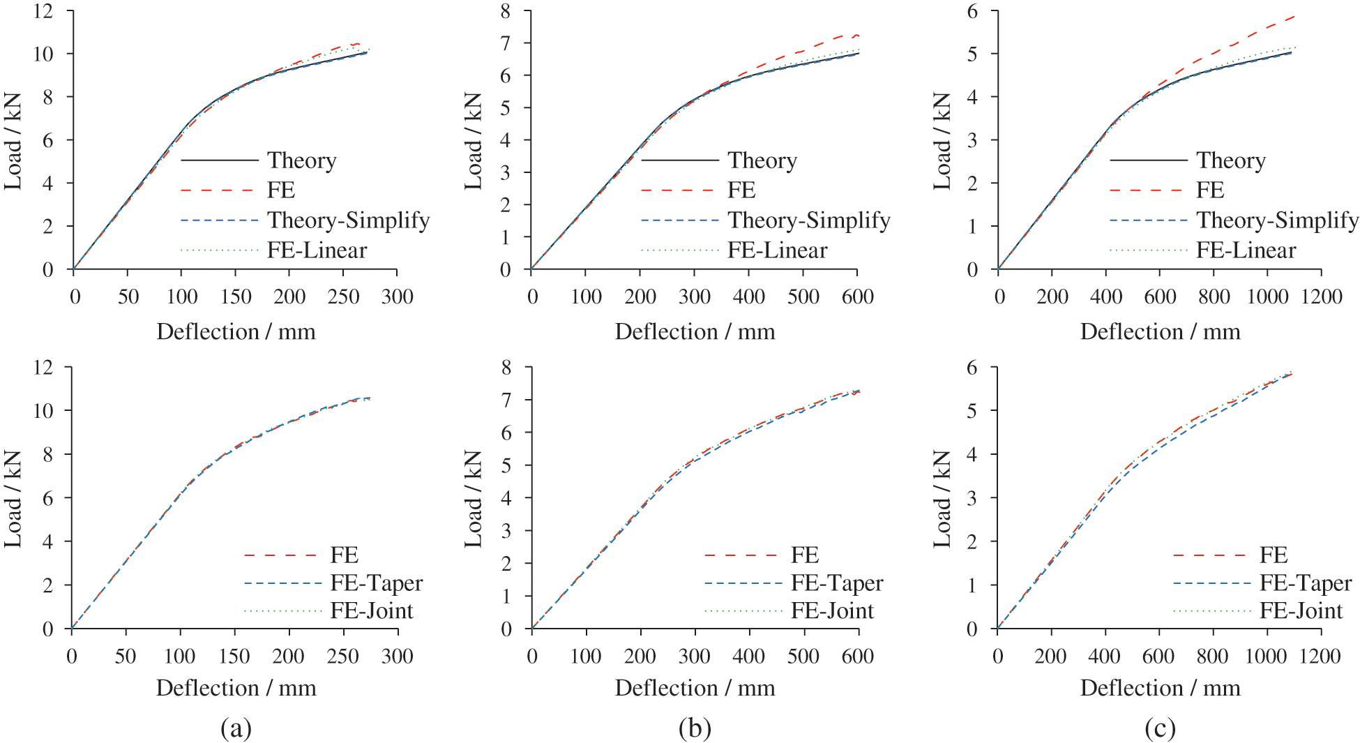
Figure 15: Comparison of theoretical and FE results for single-pole bamboo beams. (a) L = 3 m, (b) L = 4.5 m and (c) L = 6 m
Fig. 16 shows the ultimate state of single-pole bamboo beams with a span of 3 m. The neutral axis moves downward due to the greater tensile strength. When the geometric nonlinearity is not considered, the horizontal displacement of the support points is negligible. After considering the taper, the deformation is asymmetric and the maximum stress occurs on the left side with a smaller section size. The stress and deformation distributions when considering the bamboo joint are the same as those of the original model.

Figure 16: Ultimate state of single-pole bamboo beams (L = 3 m). (a) Stress distribution (Unit: MPa) and (b) Deformation distribution (Unit: mm)
3.2 Double-Pole Bamboo Beam without Interfacial Slippage
Fig. 17 depicts the FE model of a double-pole bamboo beam. The modeling strategy was identical to that of a single-pole bamboo beam. The axial connector was adopted to simulate the tangential interaction of the top and bottom bamboo poles. The normal interaction was determined as a hard contact. Two bamboo poles were evenly divided into thirty sections along the axis and thirty connectors were installed. For different spans, each connector joined different beam lengths. When the spans were 3 m, 4.5 m, and 6 m, the connected lengths

Figure 17: FE model of a double-pole bamboo beam
Fig. 18 compares the theoretical and FE results for a double-pole bamboo beam. The FE results match well with the theoretical results Eqs. (63)–(67). The deformation capacity of single-pole bamboo beams is twice that of double-pole bamboo beams. Therefore, the influence of geometric nonlinearity is not obvious in double-pole bamboo beams. Owing to the reverse placement of two poles, the influence of the taper is reduced.

Figure 18: Comparison of theoretical and FE results for double-pole bamboo beams. (a) L = 3 m, (b) L = 4.5 m and (c) L = 6 m
Fig. 19 displays the ultimate state of double-pole bamboo beams with a span of 3 m. Interfacial slippage is not observed in the four FE models and the neutral axis moves downward. The horizontal displacement of the support points is small and the influence of geometric nonlinearity is restricted. The stress and deformation distributions also illustrate that the taper has little effect on the flexural behavior of double-pole bamboo beams.
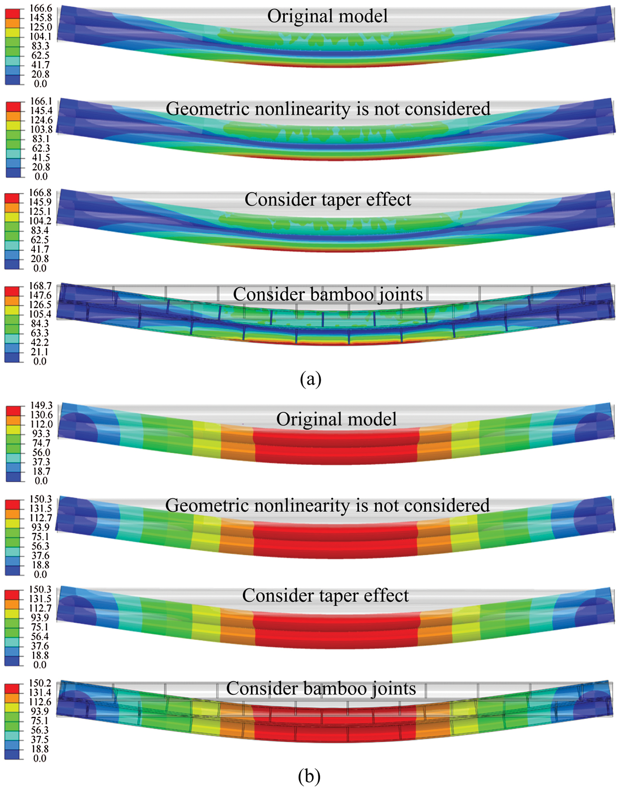
Figure 19: Ultimate state of double-pole bamboo beams (L = 3 m). (a) Stress distribution (Unit: MPa) and (b) Deformation distribution (Unit: mm)
3.3 Double-Pole Bamboo Beam with Interfacial Slippage
The theoretical analysis of the interfacial slippage is only suitable for the elastic stage [39–41]. The FE analysis can compensate for this. Four FE models, with different connector stiffnesses
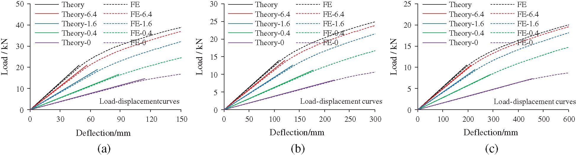
Figure 20: Load-deflection curves with interfacial slippage. (a) L = 3 m, (b) L = 4.5 m and (c) L = 6 m
Fig. 21 compares the slippage distribution of double-pole bamboo beams in the elastic stage. The theoretical analysis of interfacial slippage proves to be correct and reasonable. The slippage is concentrated at the beam ends. With increasing connector stiffness, the interfacial slippage gradually decreases. Fig. 22 shows the interfacial shear force of the double-pole bamboo beams when the connector stiffness is 6.4 kN/mm. The interfacial shear force is equal to the axial force on the connectors. Considering symmetry, only the axial force of the fifteen connectors on the left side of the bamboo beam are presented. The connectors are numbered from left to right. Connector 1 is near the left support point and the axial force there is the greatest. Fig. 23 displays the ultimate states of the double-pole bamboo beams when the connector stiffness is 0 kN/mm. Two neutral axes are observed in the top and bottom bamboo poles. The stress distribution is similar to that of a single-pole bamboo beam. Significant interfacial slippages are observed at both ends of the double-pole bamboo beams.

Figure 21: Slippage distribution of the double-pole bamboo beams. (a) L = 3 m, (b) L = 4.5 m and (c) L = 6 m
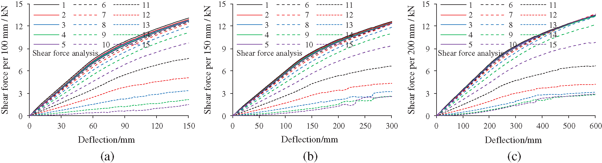
Figure 22: Shear force analysis of the double-pole bamboo beams. (a) L = 3 m, (b) L = 4.5 m and (c) L = 6 m

Figure 23: Ultimate state of double-pole bamboo beams with interfacial slippage. (a) Stress distribution (Unit: MPa) and (b) Deformation distribution (Unit: mm)
3.4 Novel Configuration to Avoid Slippage
Fig. 24 proposes a novel configuration to avoid slippage. Two bamboo poles are bound together using diagonal steel bands. The inclination of the steel band conforms to the direction of slippage. Owing to the diagonal arrangement, the tension stiffness of the steel bands is converted to horizontal shear stiffness between the two bamboo poles. The top and bottom areas of the steel band compressing the bamboo poles should be firmly fixed to the poles. Structural adhesives and pneumatic nails are two recommended methods. The methods should not damage the poles [24,25].

Figure 24: FE model of a double-pole bamboo beam with diagonal steel bands (L = 3 m)
The diagonal steel bands should meet the two requirements of stiffness and strength. Fig. 25 shows the stiffness of a single diagonal steel band
where

Figure 25: Mechanical diagram and FE model of a single diagonal steel band
The steel band cannot be sufficiently broad for the shear deformation to cause uneven stretching. Thus, a steel band width of 20 mm is suggested. The thickness of 2 mm is decided to facilitate fabrication. An ideal elastic-plastic constitutive model is adopted for the following analysis and the yield stress of the steel band is 235 MPa. Fig. 26 shows the results of the theoretical analysis. The ratio of

Figure 26: Results of theoretical analysis for a single diagonal steel band. (a) S – θb, (b) Fu – θb, (c) m – θb, (d) S/m – θb and (e) Fu/m – θb

Figure 27: FE results of a single diagonal steel band
The steel band combined with bamboo is also simulated. The FE model is illustrated in Fig. 25. The length of the bamboo sample is 500 mm, which is sufficient to analyze the stiffness of the diagonal steel band in working conditions. The steel band is attached to the top and bottom surfaces of the bamboo. A shell element, S4R, with a mesh size of 4 mm, is implemented for the steel band. Fig. 27 presents the FE results. The stiffness
Based on the model FE-0, a double-pole bamboo beam with diagonal steel bands is assembled, as shown in Fig. 24. The spacing of the diagonal steel bands is equivalent to the connected length
When the span is 3 m and the spacing is 100 mm, the interfacial slippage can be restrained. Its load-deflection curve is consistent with that of the FE model without slippage. The shear stiffness of the interface per unit length
Table 2: Details of a double-pole bamboo beam with diagonal steel bands


Figure 28: Load-deflection curves with diagonal steel bands. (a) L = 3 m, (b) L = 4.5 m and (c) L = 6 m
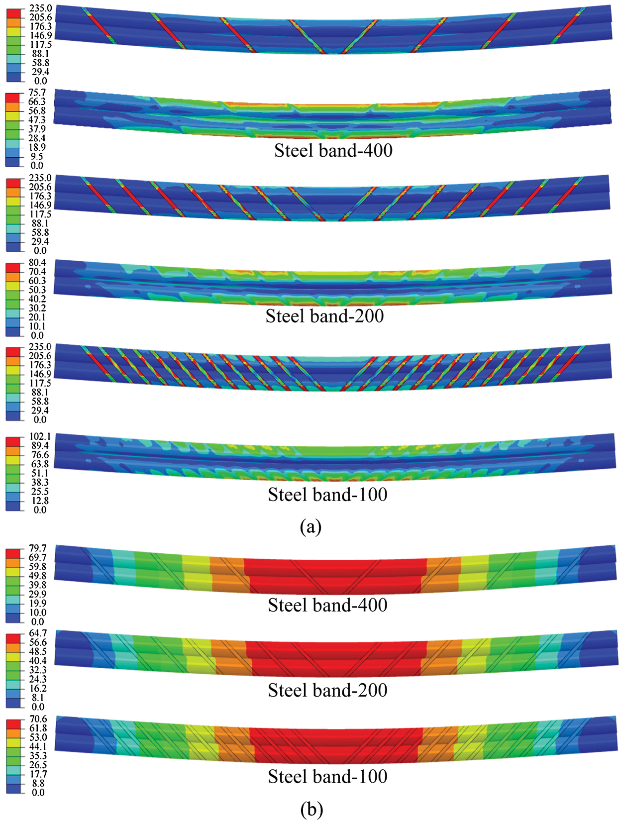
Figure 29: Ultimate state of double-pole bamboo beams with diagonal steel bands (L = 3 m). (a) Stress distribution (Unit: MPa) and (b) Deformation distribution (Unit: mm)
In this study, the flexural behavior of single-pole and double-pole bamboo beams was investigated via theoretical analysis. Simultaneously, the influence of interfacial slippage was analyzed. Then, an effective configuration to avoid slippage was proposed and validated. The following conclusions can be drawn:
1. A method for calculating the load-deflection curve is proposed, considering the material’s nonlinearity. FE analysis is conducted to validate the calculation method. The FE results match well with the theoretical results. Moreover, the FE results indicate that the influences of the poles’ natural taper and bamboo joints are limited.
2. The interfacial slippage between the two bamboo poles is difficult to avoid in double-pole bamboo beams. The shear stiffness of the interface per unit length has a significant influence on the flexural behavior of double-pole bamboo beams. For different shear stiffnesses, the load-deflection curves are obtained via theoretical and FE analyses.
3. A novel configuration using diagonal steel bands is presented to avoid slippage. Owing to the diagonal arrangement, the tension stiffness of the steel band can be converted to horizontal shear stiffness between the two bamboo poles. An inclination angle of 45° is suggested to adequately develop the stiffness and bearing capacity of the band.
Funding Statement: This research was supported by the National Key Research and Development Program of China (Grant No. 2017YFC0703502), the National Natural Science Foundation of China (Grant No. 51608433), the Key Lab of Plateau Building and Eco-Community in Qinghai (KLKF-2020-001), and the Shaanxi Province Youth Science and Technology New Star Program (Grant No. 2019KJXX-040). These financial supports are greatly acknowledged.
Conflicts of Interest: The authors declare that they have no conflicts of interest to report regarding the present study.
1. International Organization for Standardization (2004). ISO 22157-1-2004. Bamboo–Determination of physical and mechanical properties–Part 1: Requirements. Geneva, Switzerland. [Google Scholar]
2. Tian, L. M., Jin, B. B., Hao, J. P. (2019). Research and application of modern bamboo structures. Engineering Mechanics, 36(5), 1–18. [Google Scholar]
3. García, J. J., Rangel, C., Ghavami, K. (2012). Experiments with rings to determine the anisotropic elastic constants of bamboo. Construction and Building Materials, 31, 52–57. DOI 10.1016/j.conbuildmat.2011.12.089. [Google Scholar] [CrossRef]
4. Akinbade, Y., Harries, K. A., Flower, C. V., Nettleship, I., Papadopoulos, C. et al. (2019). Through-culm wall mechanical behaviour of bamboo. Construction and Building Materials, 216(1), 485–495. DOI 10.1016/j.conbuildmat.2019.04.214. [Google Scholar] [CrossRef]
5. Liu, P. C., Zhou, Q. S., Jiang, N., Zhang, H., Tian, J. F. (2020). Fundamental research on tensile properties of phyllostachys bamboo. Results in Materials, 7, 100076. DOI 10.1016/j.rinma.2020.100076. [Google Scholar] [CrossRef]
6. Qiu, Z. Y., Fan, H. L. (2020). Nonlinear modeling of bamboo fiber reinforced composite materials. Composite Structures, 238(1), 111976. DOI 10.1016/j.compstruct.2020.111976. [Google Scholar] [CrossRef]
7. Chung, K. F., Yu, W. K. (2002). Mechanical properties of structural bamboo for bamboo scaffoldings. Engineering Structures, 24(4), 429–442. DOI 10.1016/S0141-0296(01)00110-9. [Google Scholar] [CrossRef]
8. Albermani, F., Goh, G. Y., Chan, S. L. (2007). Lightweight bamboo double layer grid system. Engineering Structures, 29(7), 1499–1506. DOI 10.1016/j.engstruct.2006.09.003. [Google Scholar] [CrossRef]
9. Paraskeva, T. S., Grigoropoulos, G., Dimitrakopoulos, E. G. (2017). Design and experimental verification of easily constructible bamboo footbridges for rural areas. Engineering Structures, 143(9), 540–548. DOI 10.1016/j.engstruct.2017.04.044. [Google Scholar] [CrossRef]
10. Villegas, L., Morán, R., García, J. J. (2019). Combined culm-slat Guadua bamboo trusses. Engineering Structures, 184(2), 495–504. DOI 10.1016/j.engstruct.2019.01.114. [Google Scholar] [CrossRef]
11. Tian, L. M., Kou, Y. F., Hao, J. P. (2019). Axial compressive behaviour of sprayed composite mortar–original bamboo composite columns. Construction and Building Materials, 215(9), 726–736. DOI 10.1016/j.conbuildmat.2019.04.234. [Google Scholar] [CrossRef]
12. Bahtiar, E. T., Malkowska, D., Trujillo, D., Nugroho, N. (2021). Experimental study on buckling resistance of Guadua angustifolia bamboo column. Engineering Structures, 228, 111548. DOI 10.1016/j.engstruct.2020.111548. [Google Scholar] [CrossRef]
13. Sá Ribeiro, R. A., Sá Ribeiro, M. G., Miranda, I. P. A. (2017). Bending strength and nondestructive evaluation of structural bamboo. Construction and Building Materials, 146(1), 38–42. DOI 10.1016/j.conbuildmat.2017.04.074. [Google Scholar] [CrossRef]
14. García-Aladín, M. F., García, H., Mosquera, L. M., García, J. J. (2014). The importance of shear in the deflection of bamboo beams. Key Engineering Materials, 600, 87–96. DOI 10.4028/www.scientific.net/KEM.600.87. [Google Scholar] [CrossRef]
15. García-Aladín, M. F., García, J. J., Correal, J. F. (2018). Theoretical and experimental analysis of two-culm bamboo beams. Proceedings of the Institution of Civil Engineers-Structures and Buildings, 171(4), 316–325. DOI 10.1680/jstbu.16.00044. [Google Scholar] [CrossRef]
16. Trujillo, D., Jangra, S., Gibson, J. M. (2016). Flexural properties as a basis for bamboo strength grading. Proceedings of the Institution of Civil Engineers-Structures and Buildings, 170(4), 1–12. [Google Scholar]
17. Nurmadina, Nugroho, N., Bahtiar, E. T. (2017). Structural grading of Gigantochloa apus bamboo based on its flexural properties. Construction and Building Materials, 157(1), 1173–1189. DOI 10.1016/j.conbuildmat.2017.09.170. [Google Scholar] [CrossRef]
18. Lorenzo, R., Mimendi, L., Li, H. T., Yang, D. (2020). Bimodulus bending model for bamboo poles. Construction and Building Materials, 262(2), 120876. DOI 10.1016/j.conbuildmat.2020.120876. [Google Scholar] [CrossRef]
19. European Committee for Standardization (2004). EN 1995-1-1, Eurocode 5: Design of timber structures–Part 1-1: General–Common rules and rules for buildings. Brussels, Belgium. [Google Scholar]
20. Standardization Administration of China (2003). GB 50005-2003. Code for design of timber structures. Beijing, China. [Google Scholar]
21. Zhang, T. C., Wang, A. L., Wang, Q. S., Guan, F. R. (2019). Bending characteristics analysis and lightweight design of a bionic beam inspired by bamboo structures. Thin-Walled Structures, 142(3), 476–498. DOI 10.1016/j.tws.2019.04.043. [Google Scholar] [CrossRef]
22. Zhang, T. C., Duan, C. M., Wang, A. L., Wang, Q. S. (2020). Dynamic modeling and optimal design of Tube–Diaphragm coupling beam inspired by bamboo. Thin-Walled Structures, 155, 106836. DOI 10.1016/j.tws.2020.106836. [Google Scholar] [CrossRef]
23. Tian, L. M., Kou, Y. F., Hao, J. P. (2019). Flexural behavior of sprayed lightweight composite mortar-original bamboo composite beams: Experimental study. Bioresources, 14(1), 500–517. [Google Scholar]
24. Villegas, L., Moran, R., Muñoz, J., García, J. J. (2019). Combined culm-slat Guadua bamboo trusses. Engineering Structures, 184(2), 495–504. DOI 10.1016/j.engstruct.2019.01.114. [Google Scholar] [CrossRef]
25. García, J. J., Moran, R. (2019). Bamboo joints with steel clamps capable of transmitting moment. Construction and Building Materials, 216(1), 249–260. DOI 10.1016/j.conbuildmat.2019.05.025. [Google Scholar] [CrossRef]
26. Villegas, L., Moran, R., Muñoz, J., García, J. J. (2015). A new joint to assemble light structures of bamboo slats. Construction and Building Materials, 98, 61–68. DOI 10.1016/j.conbuildmat.2015.08.113. [Google Scholar] [CrossRef]
27. Wang, F. L., Yang, J. (2020). Experimental and numerical investigations on load-carrying capacity of dowel-type bolted bamboo joints. Engineering Structures, 209, 109952. DOI 10.1016/j.engstruct.2019.109952. [Google Scholar] [CrossRef]
28. Mouka, T., Dimitrakopoulos, E. G. (2021). Simulation of embedment phenomena on bamboo culms via a modified foundation modelling approach. Construction and Building Materials, 275(7), 122048. DOI 10.1016/j.conbuildmat.2020.122048. [Google Scholar] [CrossRef]
29. Sharma, B., Gatoo, A., Bock, M., Ramage, M. H. (2015). Engineered bamboo for structural applications. Construction and Building Materials, 81(2), 66–73. DOI 10.1016/j.conbuildmat.2015.01.077. [Google Scholar] [CrossRef]
30. Sun, X. F., He, M. J., Li, Z. (2020). Novel engineered wood and bamboo composites for structural applications: State-of-art of manufacturing technology and mechanical performance evaluation. Construction and Building Materials, 249(6780), 118751. DOI 10.1016/j.conbuildmat.2020.118751. [Google Scholar] [CrossRef]
31. Huang, D. S., Zhou, A. P., Bian, Y. L. (2013). Experimental and analytical study on the nonlinear bending of parallel strand bamboo beams. Construction and Building Materials, 44(5), 585–592. DOI 10.1016/j.conbuildmat.2013.03.088. [Google Scholar] [CrossRef]
32. Li, H. T., Wu, G., Zhang, Q. S., Deeks, A. J., Su, J. W. (2018). Ultimate bending capacity evaluation of laminated bamboo lumber beams. Construction and Building Materials, 160(4), 365–375. DOI 10.1016/j.conbuildmat.2017.11.058. [Google Scholar] [CrossRef]
33. Wei, Y., Ji, X. W., Duan, M. J., Li, G. F. (2017). Flexural performance of bamboo scrimber beams strengthened with fiber-reinforced polymer. Construction and Building Materials, 142(2), 66–82. DOI 10.1016/j.conbuildmat.2017.03.054. [Google Scholar] [CrossRef]
34. Wang, Z. Y., Wei, Y., Li, N., Zhao, K., Ding, M. M. (2020). Flexural behavior of bamboo-concrete composite beams with perforated steel plate connections. Journal of Wood Science, 66(4), 1–20. DOI 10.1186/s10086-020-1848-7. [Google Scholar] [CrossRef]
35. Zhong, Y., Wu, G. F., Ren, H. Q., Jiang, Z. H. (2017). Bending properties evaluation of newly designed reinforced bamboo scrimber composite beams. Construction and Building Materials, 143(1), 61–67. DOI 10.1016/j.conbuildmat.2017.03.052. [Google Scholar] [CrossRef]
36. Wei, Y., Yan, S. C., Zhao, K., Dong, F. H., Li, G. F. (2020). Experimental and theoretical investigation of steel-reinforced bamboo scrimber beams. Engineering Structures, 223, 111179. DOI 10.1016/j.engstruct.2020.111179. [Google Scholar] [CrossRef]
37. Li, Y. S., Shan, W., Shen, H. Y., Zhang, Z. W., Liu, J. Z. (2015). Bending resistance of I-section bamboo–steel composite beams utilizing adhesive bonding. Thin-Walled Structures, 89(5), 17–24. DOI 10.1016/j.tws.2014.12.007. [Google Scholar] [CrossRef]
38. Akinbade, Y., Nettleship, I., Papadopoulos, C., Harries, K. A. (2020). Modelling full‑culm bamboo as a naturally varying functionally graded material. Wood Science and Technology, 55(1), 155–179. DOI 10.1007/s00226-020-01246-6. [Google Scholar] [CrossRef]
39. Tian, L. M., Wei, J. P., Huang, Q. X., Ju, J. W. (2021). Collapse-resistant performance of long-span single-layer spatial grid structures subjected to equivalent sudden joint loads. Journal of Structural Engineering, 147(1), 04020309. DOI 10.1061/(ASCE)ST.1943-541X.0002904. [Google Scholar] [CrossRef]
40. Tian, L. M., He, J. X., Zhang, C. B., Bai, R. (2021). Progressive collapse resistance of single-layer latticed domes subjected to non-uniform snow loads. Journal of Constructional Steel Research, 176(8), 106433. DOI 10.1016/j.jcsr.2020.106433. [Google Scholar] [CrossRef]
41. Tian, L. M., Kou, Y. F., Lin, H. L., Li, T. J. (2021). Interfacial bond–slip behavior between H-shaped steel and engineered cementitious composites (ECCs). Engineering Structures, 231(1), 111731. DOI 10.1016/j.engstruct.2020.111731. [Google Scholar] [CrossRef]
 | This work is licensed under a Creative Commons Attribution 4.0 International License, which permits unrestricted use, distribution, and reproduction in any medium, provided the original work is properly cited. |