| Journal of Renewable Materials |
DOI: 10.32604/jrm.2021.014722
ARTICLE
Experimental Study on the Mechanical Performance of Mortise-Tenon Joints Reinforced with Replaceable Flat-Steel Jackets
1Co-Innovation Center of Efficient Processing and Utilization of Forest Resources, College of Materials Science and Engineering, Nanjing Forestry University, Nanjing, 210037, China
2Key Laboratory of Concrete and Prestressed Concrete Structures of Ministry of Education, Southeast University, Nanjing, 210096, China
3Guangdong Architectural Design Research Institute Co., Ltd., Guangzhou, 510000, China
*Corresponding Author: Hongmin Li. Email: lihongmin@njfu.edu.cn
Received: 23 October 2020; Accepted: 27 November 2020
Abstract: The mortise-tenon joint is an important hub transmitting and distributing external loads for load-bearing components (beams, columns et al.) in the ancient-timber frame structure system. However, the conventional steel hoop reinforcement methods often insert wood screws into the timber components. When the reinforced joint rotates greatly, the anchoring failure of the screws will cause damage to the timber joint. To solve this problem, this study proposes a detachable and replaceable non-destructive flat-steel jacket reinforcement method in which horizontal flat steel is placed in the center of the joint, and the bolt is extended to the outside of the timber beam. Nine 1:3.52 scaled straight-tenon joint specimens were subjected to monotonic loading of beam ends, including three unreinforced reference joints, three joints with flat-steel jacket and three carbon fiber-reinforced plastic (CFRP) reinforced joints. The mechanical behaviors of the novel joints with flat-steel jacket were experimentally studied by comparing with those of the joints without strengthening and retrofitted with CFRP, based on the failure modes, the initial stiffness, the ultimate bearing capacity, and the moment-rotation relationship curves. Results indicated that the mortise-tenon joints reinforced with flat-steel jackets maintain the original semi-rigid properties of the unreinforced mortise-tenon joints and can effectively prevent the tenon from pulling out. The initial stiffness and ultimate bearing capacity were improved markedly. The column and beam of the reinforced joints remain intact providing the reference for the practical application of joints reinforcement. The mortise-tenon joints reinforced with CFRP lose the semi-rigid properties of the unreinforced tenon -mortise joints. The joints reinforced with CFRP have the largest initial stiffness, while the unreinforced joints have the lowest stiffness. The initial stiffness of the proposed joint is in between the joints reinforced with CFRP and unreinforced joints. The ultimate bearing capacity of the joints reinforced with flat-steel jacket is larger than the other two joints, whereas the unreinforced joints have the lowest ultimate bearing capacity.
Keywords: Mortise-tenon joints; replaceable flat-steel jacket; FRP; relationship between moment and rotation; amount of tenon pulled out
The mortise-tenon joints are the main connection between the timber components in Chinese ancient timber buildings and used to transmit and distribute external loads (Fig. 1). They are also the main energy dissipation parts of timber structures during earthquakes [1−5] and so they are always the first part to fail. The research on the reinforcement technology of mortise-tenon joints has always been a hotspot and many achievements have been obtained [6−10]. Stable back wedge, “iron pulling” (flat steel, climbing nails, etc.), and supporting wood to fix the tenon are the main traditional retrofitting methods for mortise-tenon joints (Fig. 2). Modern strengthening measures are mainly metal reinforcement (bolts, steel plates, iron hoops, steel tie, etc.), fiber-reinforced plastic (FRP) reinforcement, and epoxy resin bonding steel reinforcement.
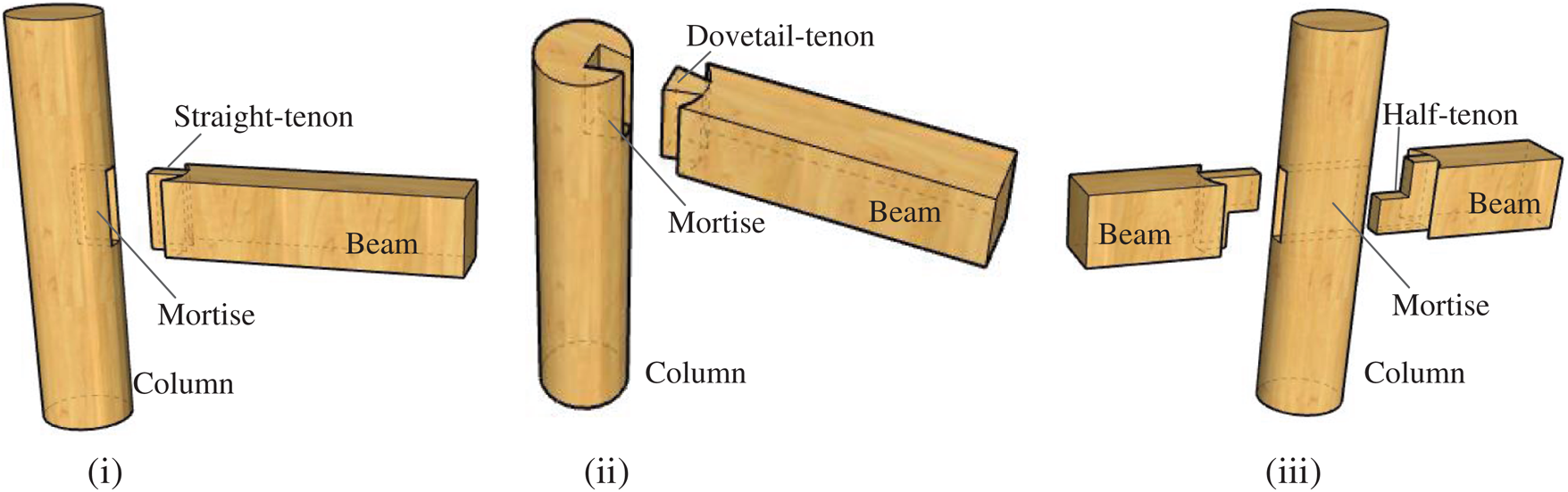
Figure 1: Schematic of the typical mortise-tenon joints. (i) Straight-tenon joint (ii) Dovetail-tenon joint (iii) Half-tenon joint
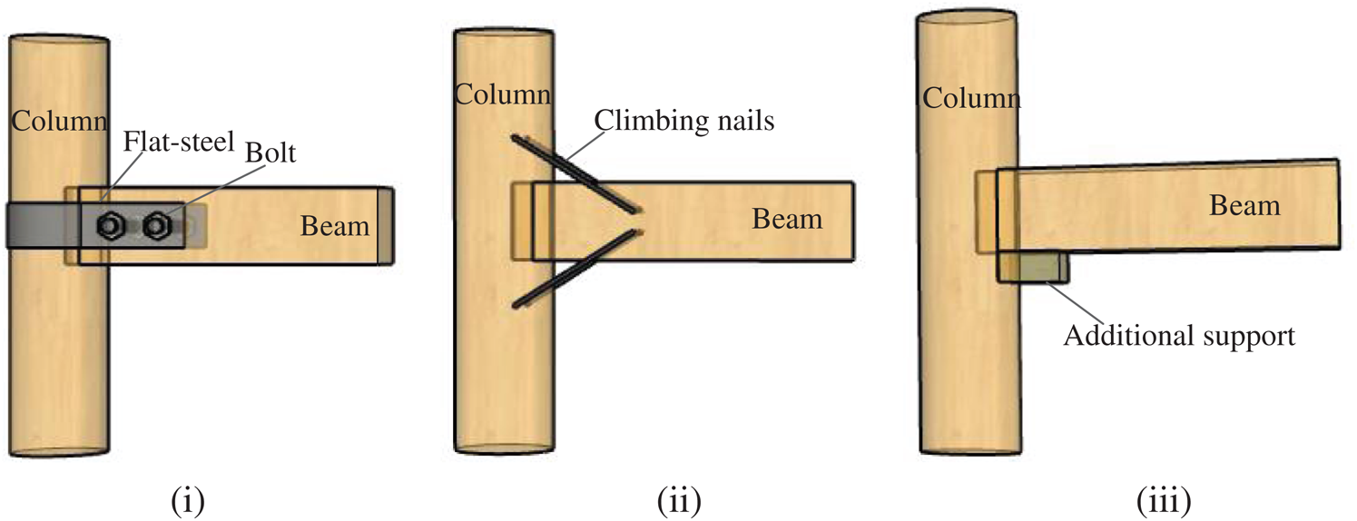
Figure 2: Schematic diagram of common reinforcement measures for mortise-tenon joints. (i) Flat-steel and bolt reinforcement (ii) Climbing nail reinforcement (iii) Additional support reinforcement
The back-wedge stabilizing reinforcement technology is a customary method for fixing timber connection joints in the processing and reinforcement of daily wood furniture in China. It can be used for the loosen mortise-tenon joints [6]; however, the effect of reinforcement is difficult to meet the durability requirements. Therefore, metal connectors are mostly used to reinforce the mortise-tenon joints. Zhou et al. [7] obtained the experimental moment-rotation hysteresis curve of mortise-tenon joints strengthened with tinplate and wood screw. The joint reinforced with tinplate was found that both the energy-dissipative capacity and amount of tenoning pull-out reduced, while the bending moment capacity was improved. Lu et al. [8] reinforced the timber frame with mortise-tenon joints with curved steel dampers, which improved the energy dissipation capability. Xue et al. [9] carried out experimental research on the mechanical property of the damaged mortise-tenon joints strengthened with flat steel and proposed the calculation formulas for the flexural capacity of flat steel reinforced damaged joints. Tannert et al. [10] and Song et al. [11] used self-tapping screws to reinforce the dovetail tenon under shear and mortise-tenon joints of the heavy wood frame, respectively, and obtained better mechanical performance. In addition to metal connectors [12] and reinforcement methods [13], materials with new properties are gradually being used in the study of the reinforcement of mortise-tenon joints. The fiber reinforced plastics (FRP) with adhesives [14] and shape memory alloy (SMA) are also used to reinforce the wood structure joints. In the research, Xie et al. [15], Xue et al. [16,17] proposed the use of super-elastic shape memory alloys to strengthen the mortise-tenon joints and conducted an experimental investigation. The energy dissipation performance of the mortise-tenon joints has been greatly improved. The mechanical properties of wood structure joints before and after retrofitting have also been studied using numerical analysis methods [18,19].
In the reinforcement of the Chinese ancient buildings, flat steel is still a common reinforcement for the mortise-tenon joints. However, most traditional methods of strengthening the tenon-and-mortise joints have some damage to the mortise-tenon joints, such as bolt hole or screw hole splitting, which is not conducive to the protection of ancient timber buildings. Therefore, this article proposes a detachable and non-destructive flat-steel jacket reinforcement method considering that the traditional flat steel reinforcement in beam-column section damage caused by bolt holes, easy splitting damage, and inconvenient disassembly. The bolt holes are arranged outside the beam of the mortise-tenon joints, and the flat-steel reinforcement is mainly relying on the extrusion and friction between the flat-steel jacket and the mortise-tenon joint. At the same time, the experimental comparison and analysis with unreinforced joints and the joints reinforced by FRP are carried out. Since the straight-tenon joints are widely used in ancient timber structures and are prone to pull-out of the tenon damage, they are adopted as the reinforcement research object. The experimental results are reported in terms of failure modes, the initial stiffness, the ultimate bearing capacity, and the relationship between moment and rotation. Finally, the results are used to evaluate the effectiveness and feasibility of these types of connections and provide a theoretical basis for the application.
The experimental study in this paper focuses on the mechanical properties of the mortis-tenon joint reinforced with the proposed flat-steel reinforcement and compared with that of the joints reinforced with FRP. The proposed reinforcement is replaceable and the mechanical properties after replacement will be studied in further study.
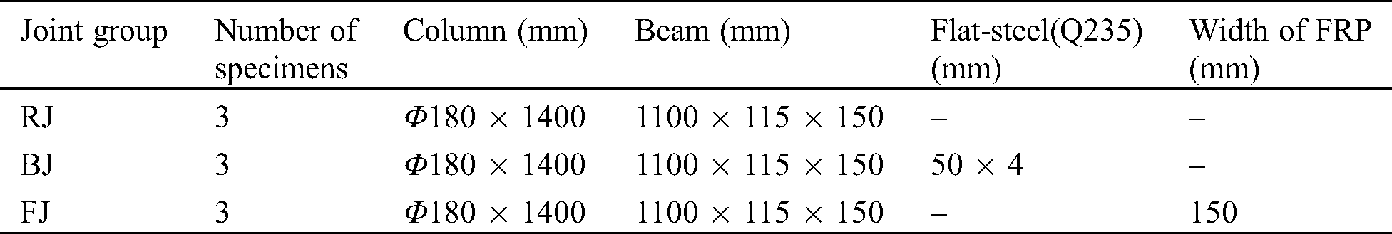
Three groups of mortise-tenon specimens were prepared and tested to investigate the effective behavior of the mortise-tenon reinforced by different techniques. Fig. 3 shows the configurations of the mortise-tenon specimens and details of the joints. The straight-tenon joints are fabricated according to the Yingzao Fashi (Rules of Architecture) in the Song Dynasty and the configurations of the mortise-tenon joint specimens in the study by Chen [20]. The scale ratio of the test components is 1:3.52. Nine straight-tenon joints with the same size are manufactured from the same batch of fir, including three unreinforced reference joints (RJ group), three joints reinforced by flat-steel jacket (BJ group) and three CFRP reinforced joints (FJ group).
In the BJ group, the shapes of the horizontal and vertical steel jackets are processed to completely fit the outer surface of the mortise-tenon joints. The connection between the horizontal steel jacket and the column only relies on the interaction of contact and friction, so that the steel jacket can slide with the rotation of the mortise-tenon. This could reduce the influence of the reinforcement on the rotation stiffness of the mortise-tenon joint. The steel jackets and the mortise-tenon joints are mainly fixed by two vertical steel jackets extending outside the beam. Both the vertical steel jacket far away from the mortise-tenon joint (flat-steel sleeve 1) and the steel jacket (flat-steel sleeve 2) at the side of the column are fastened by bolts extending outside the beam. The main functionality of the flat-steel sleeve 2 is to ensure a reliable connection between the horizontal flat steel jacket and the mortise-tenon joint. In this study, the flat-steel jackets, as a reinforcement solution, can be replaceable. A detailed configuration of the proposed flat-steel jackets is presented in Figs. 3ii and 4ii. Four bolts are used to connect the jackets with the beam. When the jackets experience severe damage, the damaged flat-steel jacket can be replaced of a new jacket through relaxing and moving the four bolts. Compared to the conventional reinforcement solution, the proposed solution can ensure the integrity of the wooden joint without the section damage of column and beam. In the FJ group, there are two layers of FRP in the horizontal hoop at the mortise-tenon joints. To increase the bonding force between the horizontal FRP hoop and the surface of the mortise-tenon joint and strengthen the restraint on the mortise-tenon joint, a single layer of FRP with a width of 60 mm is selected as the hoop at the mortise joint. The hoop is used to prevent the peeling of the horizontal hoop at the corner of the mortise-tenon joint from affecting the reinforcement of the FRP. Besides, the FRP with a width of 50 mm is pasted on both sides of the column close to the mortise-tenon joint to prevent the horizontal hoop from peeling off at the mortise-tenon joint. A summary of groupings and the mortise-tenon joints dimensions is given in Tab. 1.
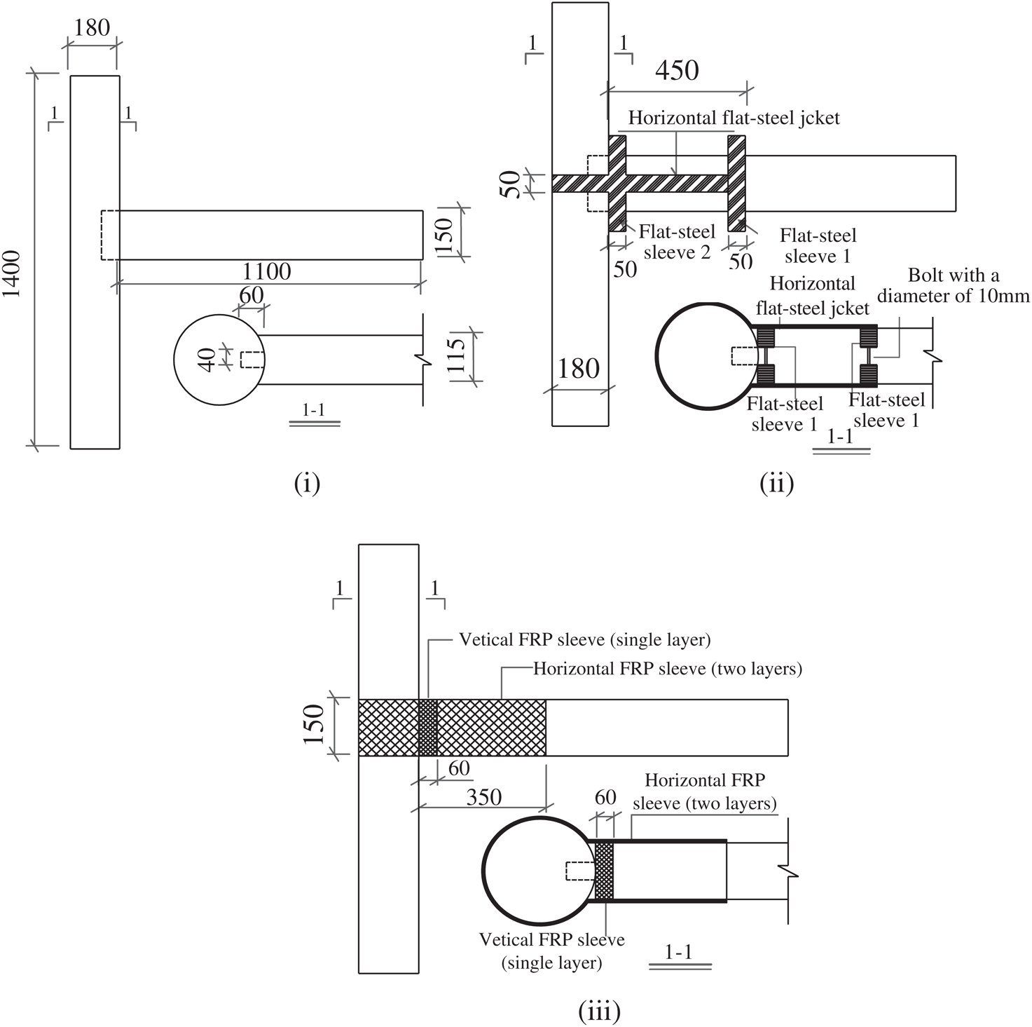
Figure 3: Configuration of mortise-tenon specimens (mm) (i) RJ group (ii) BJ group (iii) FJ group
Table 1: Summary of 9 tested mortise-tenon joints
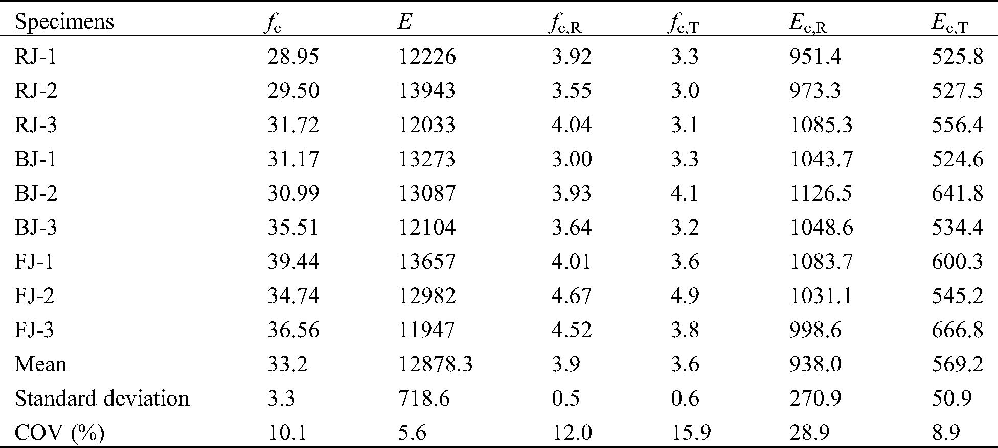
The Chinese fir (Cunninghamia lanceolata), one of the most significant timber species used widely in Chinese ancient buildings, is used in this study. The moisture content and density are 10.9% and 380 kg/m3, respectively. Because of the variation of the material properties in natural timber, material samples were taken from each mortise-tenon joint specimen and tested to determine the material properties [21−23]. The mechanical properties are listed in Tab. 2, in which fc, Ec, fc, R, fc,T, Ec,R and Ec,T denote respectively the compressive strength along the wood grain, compressive modulus of elasticity along the wood grain, the compressive strength perpendicular to the grain in the radial direction, the compressive strength perpendicular to the grain in the tangential direction, compressive modulus of elasticity perpendicular to the grain in the radial direction and compressive modulus of elasticity perpendicular to the grain in the tangential direction. The maximum and minimum coefficients of the variation (COV) in these mechanical properties are Ec and Ec,R with values of 5.6% and 28.9%, respectively.
Table 2: Material properties of mortise-tenon joints specimens (MPa)
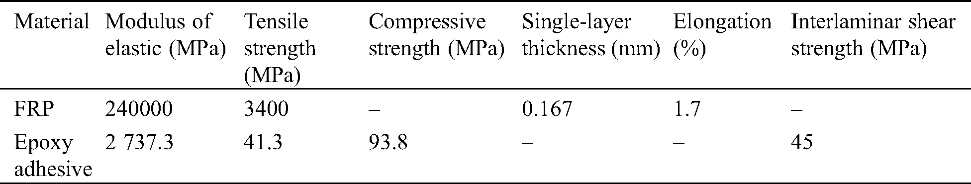
The flat-steel jacket specification selected for the reinforcement test is Q235 steel. The yield tensile strength, the ultimate tensile strength, and the elongation were found to be 235 MPa, 370 MPa, and 25.5%, respectively [24]. The material mechanical properties of FRP and glue used in the test are shown in Tab. 3.
Table 3: Material properties of the FRP and epoxy adhesive
2.3 Test Program for Mortise-Tenon Specimens
The test preparation and the arrangement of the displacement transducers are shown in Fig. 4. To simulate the actual stress state of the frame column in the ancient wooden building, the column foot is supported with hinged support, and the vertical load on the top of the column applied by jack 1 is 20 kN. The vertical load on the beam end is applied by the hand jack (jack 2) supported on spherical hinge support, which can prevent the jack from shifting in the later stage of loading. The load is controlled by displacement with a rate of 10 mm/min. To ensure good contact between the test specimens and the support, three preloads are carried out before the formal loading starts. The three preload displacements are 5 mm, 10 mm, and 10 mm respectively. In the formal loading, an increase of 10 mm per step is used as the control displacement, and the time for each loading is about 1 minute. The test should continuously load up to failure (when the mortise-tenon joints fail to bear loading or the range of the jack is finished).
A force sensor is arranged between the spherical hinge support and the beam to measure the vertical load applied on the beam (Fig. 4). Two displacement transducers numbered LVDT1 and LVDT2 with a measuring range of ±50 mm, are arranged respectively on the upper and the lower sides of the beam near the joint zone. They are used to measure the relative sliding between the mortise and tenon. The relative sliding is the relative horizontal displacement between the axis of the beam end and the column side, named as the amount of tenon pulled out from the mortise δb. The rotation angle θ of the joint between the beam end and the column side can be obtained from the ratio of δb to the vertical distance between LVDT1 and LVDT2. Since the local deformation of the loading point influences the measurement of the vertical displacement, LVDT3 is arranged at the point with a distance of 500 mm to the mortise-tenon joint to evaluate the vertical displacement of the loading point. At the same time, a force sensor is arranged to measure the load P applied to the beam.
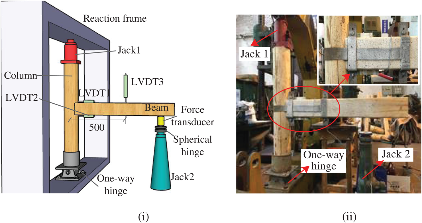
Figure 4: Test setup and instrumentation (mm) (i) Schematic of setup RJ Group (ii) Picture of the test preparation
3.1 General Observation and Failure Modes
For the reference Group RJ, the load rises quickly in the initial stage of loading. When the loading displacement reached 20–40 mm, the wood squeezing sound was heard, and the tenon pull-out amount is about 3 mm. When the loading displacement reached 120 mm, there was a sound from the friction between the mortise and tenon, associated with a slight internal crack and splitting sound. At this stage, as the loading displacement increases, the loading speed becomes slow, and the splitting sound becomes larger. When the loading displacement reached 120–140 mm, the joint enters the plastic-yield stage, the bearing capacity remains unchanged, stabilizing at 0.7 kN. When loading displacement reaches 180 mm, the wood fiber on the lower end of the mortise is torn, and the load is slightly reduced. With loading displacement continues to increase (200–210 mm), the main failure mode is the pulling-out of the tenon from the mortise (Fig. 5ii). The upper part of the mortise and the lower part of the tenon is significantly deformed by extrusion (Figs. 5i and 5ii), and the column and beam are intact. At this time, the load drops to 30% of the maximum bearing capacity.
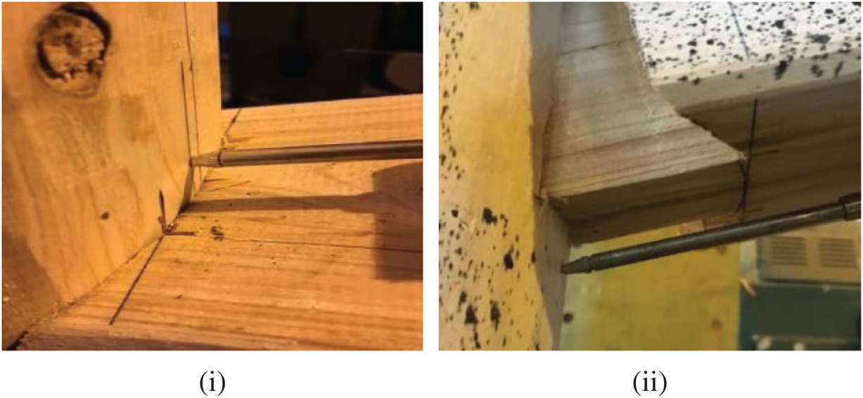
Figure 5: The failure mode of the Group RJ (i) Extrusion of the upper part of the mortise (ii) Pulling-out of the tenon
For the Group BJ, the load rises faster than that of the Group RJ in the initial stage of loading. The friction sound between steel sleeves and wood and the squeezing sound from the joints increases with the increase of loading displacement. When the displacement increases to 9–14 mm, the upper part of the beam deforms greatly, the tenon neck squeezes the column (Fig. 6i), and the increasing amplitude of the load becomes slow. When the loading displacement reaches 26–32 mm, the flat-steel sleeve 1 begins to slip, which is associated with audible sound (Fig. 6ii). When the joints are loaded to a displacement of about 60 mm, the flat-steel sleeve 2 near the joint is stretched and contacted the column (Fig. 6iii). When the loading displacement reaches 130 mm, the bearing capacity of the mortise-tenon joint reaches the peak value and remains about 4 kN. At this time, the joint enters the plastic-yield stage. The test finishes in the loading displacement of about 220 mm. Therefore, the initial load of the mortise-tenon joint reinforced with flat-steel jacket increases rapidly, and the steel jackets slip until the load reaches about 50% of the peak load. Under the 70% of the peak load, the flat-steel sleeve 2 contacts the column.
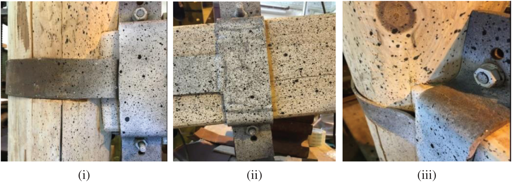
Figure 6: The failure mode of the Group BJ (i) Tenon neck squeezed the column (ii) Slip of the flat-steel sleeve 1 (iii) Flat-steel sleeve 2 contacted the column
Due to the close fit between the FRP and the mortise-tenon joint, FRP presents its good tensile performance at the beginning of loading. The mortise-tenon joint reinforced with FRP exhibits the characteristics of rigid joint. The load tends to rise in a straight line and the initial displacement is very small. Until the load reaches 45% of the peak load, the squeeze sound of the joint and peeling sound of the FRP adhesive occur. When the load reaches about 60% of the peak load, the FRP in the upper part of the tenon neck happens squeezed wrinkle. At 90% of the peak load, the FRP pasted on both sides of the column close to the mortise-tenon joint suddenly peeled off (Fig. 7i), which cause the vertical FRP ring to become loose and the load dropped to 60% of the peak load. As the loading displacement increases, the rotation of the joint increases and the FRP ring is tightened again. When the load reaches 80% of the peak load, the FRP in the lower edge of the beam end begins to tear (Fig. 7ii). At the peak load, the lower edge of the FRP tears to half of the original width. The load begins to slowly drop with the tear of the FRP. When the FRP is completely torn, the load drops to 60% of the maximum bearing capacity, and the lower part of the tenon is deformed significantly (Fig. 7iii). The destruction of components is still concentrated in the joint area.
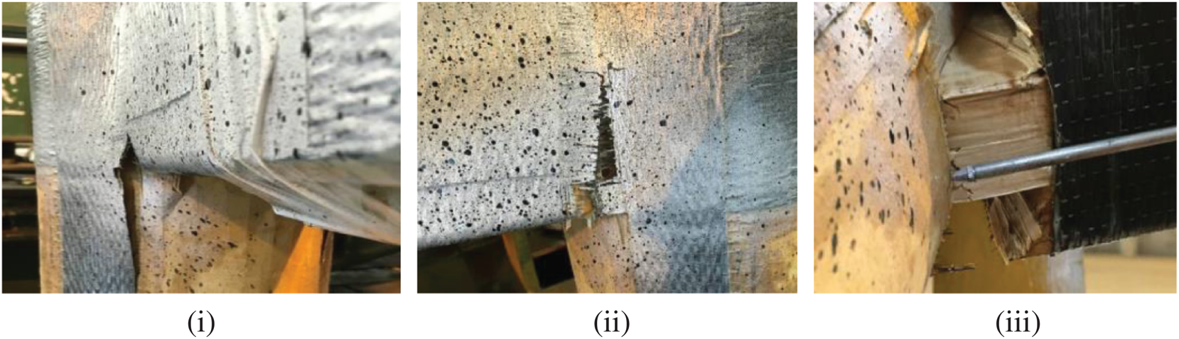
Figure 7: The failure mode of the Group FJ (i) Peeling of the FRP in the corner (ii) Tear of the FRP in the lower edge (iii) Squeeze of the tenon bottom
3.2 Moment-Rotation Relationship (M-θ) Curves
The M-θ curve of a mortise-tenon joint is the relationship between the bending moment and rotation angle of the joint, which can quantitatively reflect the mechanical properties of the joint under load, such as stiffness, strength, and ductility.
3.2.1 Definition and Calculation of the Moment and Rotation Angle
Since the beam end is supported ahead of the setup of the displacement transducers, the measured rotation angle of the beam includes the rotation caused by the weight of the beam. The bending moment of the joint should include the clockwise moment generated by the weight of the wooden beam and the counterclockwise moment generated by the loading displacement. From Fig. 8, the bending moment of the mortise-tenon joint can be calculated as:


where, M is the bending moment of the joint; P is the vertical load, the downward pressure is specified as negative, and the upward push is positive; L1 is the distance from the loading point to the edge of the column, L1 = 840 mm; Mg is the bending moment of the mortise-tenon joint generated by its weight; L is the beam length; ρ, h and b are the density of the wood, the height, and width of the beam section, respectively.
From Fig. 8, ignoring the influence of the bending deformation between the two displacement transducers (LVDT1 and LVDT2) and the side of the column, the rotation angle of the joint can be obtained from the value of these two displacement transducers:

where θ is the rotation angle of the joint; δ1 and δ2 are the measured values of displacement transducer 1 (LVDT1) and displacement transducer 2 (LVDT2) respectively. The value of the displacement transducers is defined as follows. The stretching is positive and compression is negative. H is the vertical distance between the axial line of the two displacement transducers, H = 160 mm.
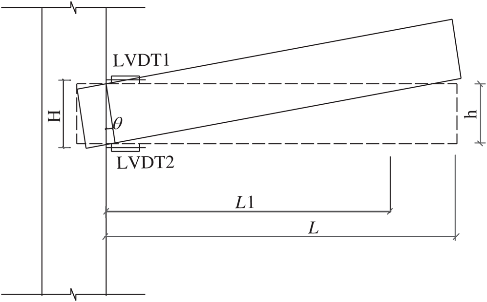
Figure 8: Schematic of the moment-rotation angle calculation for straight-tenon joint
3.2.2 Moment-Rotation Angle Curves
The moment-rotation angle curves of the unreinforced mortise-tenon joints (RJ group) are shown in Fig. 9i. The basic trends of the three curves are the same as each other, which shows three stages of “rising-gentle-falling” [20]. At the beginning of loading, the wood of the joint is in the elastic stage and the bending moment of the joint increases almost linearly (see Fig. 9i). The curve shows an upward trend. After the wood fiber on the contact surface between the mortise and the tenon enters the yield stage, the increase of the bending moment becomes slow and the curve slope decreases. This means the flexural rigidity of the joint decreases (Fig. 10i). With the loading increasing, the tenon continues to yield and is pulled out from the mortise. The contact area between the tenon and mortise gradually decreases and the load begins to drop. During the loading process, the joints are accompanied by a non-negligible rotation angle, especially, after the wood fiber of the tenon yields. Therefore, the joints show semi-rigid characteristics.
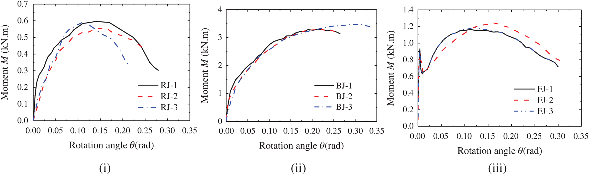
Figure 9: Moment-rotation angle curves (i) RJ group (ii) BJ group (iii) FJ group
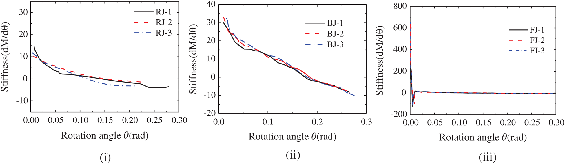
Figure 10: Stiffness-rotation angle curves (i) RJ group (ii) BJ group (iii) FJ group
Fig. 9ii shows the moment-rotation angle curves of the mortise-tenon joints reinforced with flat-steel jackets (BJ group). Similar to the RJ group, the curve presents three basic stages of “rising-gentle-falling.” Due to the relative sliding between the joints and the flat-steel jacket, and the yield of the flat steel, the flat stage of curves of the BJ group is longer than that of the RJ group. Since the rotation angle of the joints increases during the loading process, the joints still show semi-rigid characteristics after reinforcement. Fig. 10ii shows that the rotational stiffness of the joints of the BJ group decreases linearly.
Unlike the former two groups, the moment-rotation angle curves of the mortise-tenon joints reinforced with FRP (FJ group) (Fig. 9iii) present five stages of “steep rise-sudden drop-rise-gentle-fall.” At the initial stage of loading, the tight packing of FRP restricted the rotation of the mortise-tenon joint completely. The rotation stiffness of the joints is very large. The curves rise almost vertically along the Y-axis. The original mortise-tenon joint with semi-rigid characteristic shows the characteristics of a rigid joint. The sudden drop of the curves corresponds to the sudden peeling of the FRP on both sides of the column. Fig. 10iii shows the trend of the rotational stiffness of the joints of the FJ group.
The moment-rotation angle curves show that the order of the initial stiffness and bearing capacity of the three groups of specimens is inconsistent. The initial stiffness of the specimens in descending order is the joints reinforced with FRP, the joints reinforced with flat-steel jacket, and the unreinforced joints. In terms of the ultimate bearing capacity of the mortise-tenon joints, the descending order is the joints reinforced with flat-steel jacket, the joints reinforced with FRP, and the unreinforced joints.
3.2.3 Ultimate Bearing Capacity and the Secant Stiffness of Moment-Rotation Angle
As can be seen in Tab. 4, the ultimate bearing moments of the three unreinforced joints (RJ group) are very close. The average value of the ultimate bending moment and the corresponding rotation angle is 0.58 kN·m, and 0.14 rad, respectively. The average value of the ultimate bearing capacity of the three joints after reinforcement by the flat-steel jackets (BJ group) is 3.35 kN·m. Due to the sliding limit between the steel sleeves, the bearing capacity result of the BJ group is higher than the expected bearing capacity, reaching 5.7 times the average bearing capacity of unreinforced joints. The increase in the moment capacity of the BJ group can be attributed to the contribution of the flat-steel jacket reinforcement. The comparison with the unreinforced specimen shows that the compression friction of the mortise and tenon itself contributes only about 17% to the bearing capacity of the reinforced joint, and the flat-steel jacket reinforcement bear the main moment capacity. The average value of the rotation angle with the peak load is 0.21 rad, which is slightly larger than that of the unreinforced joints. The average ultimate bending moment of the FJ group is 1.2 kN·m. Due to the high tensile strength of FRP and the double-layer reinforcement at the joint, the bearing capacity of the FJ group is lower than the expected bearing capacity after reinforcement, which is close to twice times the bearing capacity of unreinforced joints; the average value of the ultimate rotation angle is 0.13 rad, which is smaller than that of unreinforced joints
Table 4: Ultimate bearing capacity, ultimate rotation angle and 0.7 times of the ultimate secant stiffness
The secant slope (secant stiffness) of the moment-rotation angle can reflect the proportional relationship between the peak bending moment and the rotation angle. In the serviceability limit state, the load generally does not reach the peak load and is in the range of 0.6 to 0.7 times the peak load. Here, the secant stiffness corresponding to 0.7 times the peak load is used for comparative analysis. The average value of the secant stiffness of the unreinforced mortise-tenon joints (RJ group) is 8.20 kN·m/rad. The secant stiffness of the mortise-tenon joints reinforced with flat-steel jackets (BJ group) is much greater than that of the unreinforced joint, reaching about 3.7 times of the unreinforced joint. The secant stiffness of the mortise-tenon joints reinforced with FRP (FJ group) under the serviceability limit state is much greater than that of the unreinforced joints, reaching about 33.0 times of the RJ group. This indicates that the FJ group does not rotate in the serviceability limit state. FRP limited the rotation of the mortise-tenon joints, and the joints in the FJ group are equivalent to rigid joints. Fig. 9iii also shows that the rotational stiffness of the FJ group reaches the maximum instantaneously at the initial stage of loading, which can be approximated as the rigid joints.
In summary, the improvement of the bearing capacity and the secant stiffness in the serviceability limit state of the BJ group compared to those of unreinforced joints are similar (5.7 times and 5.31 times). The joints in the BJ group also maintain the semi-rigid characters of the unreinforced mortise-joint. For the FJ group, reasonable design can make the bearing capacity of joints close to the unreinforced joints, and the rigidity improves greatly. In the serviceability limit state, the joints reinforced with the FRP could have the characteristics of the rigid joint and maintain their failure order in the components of the ancient building.
3.3 Relationship between the Amount of Tenon Pulled Out and Rotation Angle
The amount of tenon pulled out is an important parameter to measure the rotation ability of mortise-tenon joints. When the amount of tenon pulled out reaches a certain value, the joints may lose load-bearing capacity or even the tenon is pulled out completely from the mortise, failing the joints. Here, the amount of tenon pulled out δb is defined as the relative displacement between the centerline of the beam and the column side [20], as shown in Fig. 11. Tenon pulling-out amount is determined by the formula (4):

where, δb is the amount of tenon pulled out; δ1 and δ2 are the measured values of displacement transducer 1 (LVDT1) and displacement transducer 2 (LVDT2), respectively. The value of the displacement transducers is defined as that stretching is positive and compression is negative.
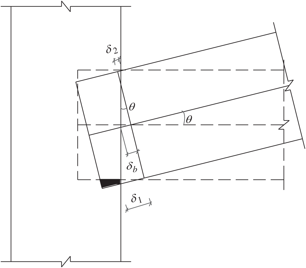
Figure 11: Schematic of the amount of tenon pulled out
The δb–θ curves are shown in Fig. 12. The δb–θ curves are in terms of the whole loading process since the FJ group performed as the rigid joints in the initial stage. The curves of each group are linear. The linear relationship of RJ and FJ groups is more obvious than that of the BJ group. During the loading process, it can be assumed that the joint rotates rigidly with the intersection of the tenon root and the beam axis as the center of rotation. Due to the dispersion of the amount of the tenon pulled out caused by the sliding of the flat-steel jackets, the relationship curves dispersion of the BJ group is maximum in three groups. Meanwhile, the stiffness of the δb–θ curves of the BJ group is the minimum, indicating the flat-steel jackets have an obvious restraint effect on tenon pulled out.
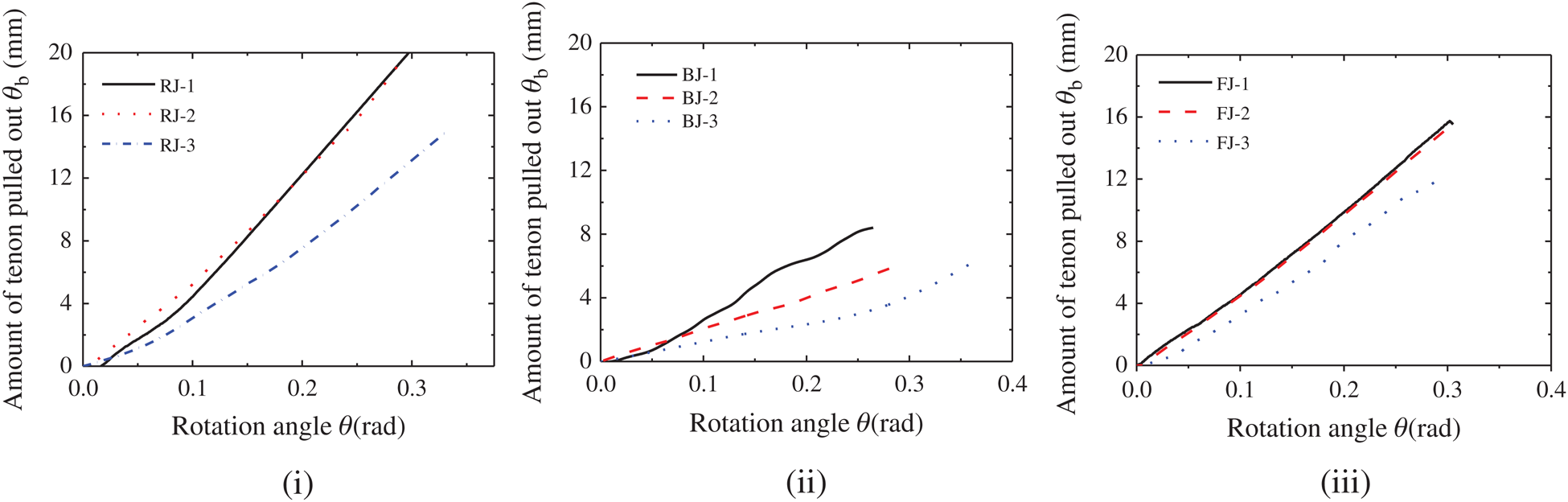
Figure 12: δb–θ curves of the straight-tenon joints (i) RJ group (ii) BJ group (iii) FJ group
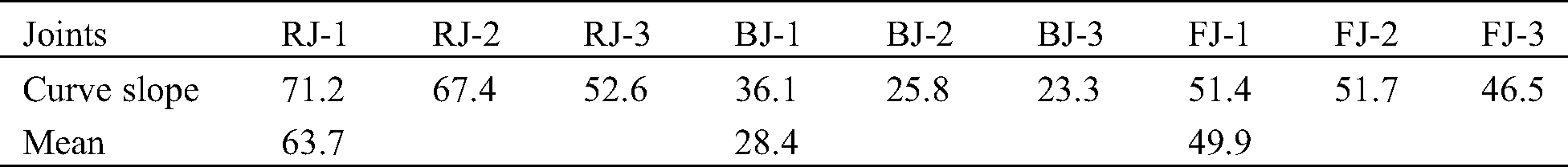
To compare the relationship between the amount of tenon pulled out and the rotation angle of each joint accurately, the δb–θ curve of each joint is linearly regressed to obtain the curve slope of each joint, listed in Tab. 5. The slope of the δb–θ curves is the largest, followed by that of the FJ group. The slope of the δb–θ curves for the BJ group is the minimum. This shows that the flat-steel jackets reinforcement has an obvious effect in controlling the amount of tenon pulled out, followed by FRP reinforcement. Therefore, when the rotation angle of the three groups is the same, the unreinforced joints have the largest amount of tenon pulled out.
Table 5: The slope of the δb-θ curves of each joint (mm/rad)
This study proposes a non-destructive flat-steel jacket reinforced joint technology that extends bolts to the outside of the beam. The mechanical performance of the unreinforced joints, joints reinforced by the flat-steel jacket, and reinforced joints with FRP are experimentally investigated and compared. The conclusion is as follows:
The failure mode of the mortise-tenon joints reinforced by the flat-steel jacket is similar to the unreinforced joints. The FRP reinforced joints performed the character of the rigid joint in the initial stage of loading.
The improvement of the bearing capacity and the secant stiffness in the serviceability limit state of the BJ group compared to those of unreinforced joints are similar. During the loading process, the joints are accompanied by a non-negligible rotation angle. The joints in the BJ group also maintain the semi-rigid characters of the unreinforced mortise-joint.
The FRP reinforced mortise-tenon joints show the character of the rigid joint at the initial loading stage. The FRP reinforcement changes the original mechanical performance of the mortise-tenon joint.
Compared to the other two joint type (i.e., the unreinforced joint and the joint wit FRP), using flat-steel jacket in mortise-tenon joints can noticeably improve the performance of the joint. Due to the easy replacement and no damage on the joint, the application of the proposed novel joint in practice is feasible.
The flat-steel jackets reinforcement has significant effects in controlling the amount of tenon pulled out. To apply this reinforcement measure in practice, the simulation analysis of the design parameters for this reinforcement method should be investigated in further study.
Funding Statement: This research was funded by the National Natural Science Foundation of China No. 51908291 and Nanjing Forestry University Youth Science and Technology Innovation Fund No. CX2019002.
Conflicts of Interest: The authors declare that they have no conflicts of interest to report regarding the present study.
1. Sandberg, L. B., Bulleit, W. M., Reid, E. H. (2000). Strength and stiffness of oak pegs in traditional timber−frame joints. Journal of Structural Engineering, 126(6), 717–723. DOI 10.1061/(ASCE)0733-9445(2000)126:6(717). [Google Scholar] [CrossRef]
2. Chun, Q., Yue, Z., Pan, J. (2011). Experimental study on seismic characteristics of typical mortise−tenon joints of Chinese southern traditional timber frame buildings. Science China Technological Sciences, 54(9), 2404–2411. DOI 10.1007/s11431-011-4448-3. [Google Scholar] [CrossRef]
3. Xie, Q., Wang, L., Zheng, P., Zhang, L., Hu, W. (2017). Rotational behavior of degraded traditional mortise−tenon joints: experimental tests and hysteretic model. International Journal of Architectural Heritage, 12(1), 125–136. DOI 10.1080/15583058.2017.1390629. [Google Scholar] [CrossRef]
4. Han, S. R., Lee, J. J. (2006). Mechanical performance of Korean traditional wooden bulding of the column−girder tenon−joint by joint type. 9th World Conference on Timber Engineering, Portland. [Google Scholar]
5. Chen, C., Qiu, H., Lu, Y. (2016). Flexural behaviour of timber dovetail mortise–tenon joints. Construction and Building Materials, 112, 366–377. DOI 10.1016/j.conbuildmat.2016.02.074. [Google Scholar] [CrossRef]
6. Shiratori, T., Komatsu, K., Leijten, A. (2008). Modified traditional Japanese timber joint system with retrofitting abilities. Structural Control and Health Monitoring, 15(7), 1036–1056. DOI 10.1002/stc.240. [Google Scholar] [CrossRef]
7. Zhou, Q., Yan, W., Li, Z., Zhang, B. (2011). Experiments on the aseismic behavior of Chinese ancient architecture mortise−and−tenon joints strengthened with iron−hooks. Sciences of Conservation and Archaeology, 23(4), 17–25. [Google Scholar]
8. Lu, W. D., Sun, W., Gu, J. J., Deng, D. L., Liu, W. Q. (2014). Experimental study on seismic performance of timber frames strengthened with curved steel dampers. Journal of Building Structures, 35(11), 151–157. [Google Scholar]
9. Xue, J. Y., Zhai, L., Zhang, F. L., Li, Y. Z. (2015). Performance analysis and design recommendations for damaged mortise−tenon joints of ancient timber structure strengthened with flat steel. Journal of Xian University of Architecture & Technology (Natural Science Edition), 47(5), 621–625. [Google Scholar]
10. Tannert, T., Lam, F. (2009). Self-tapping screws as reinforcement for rounded dovetail connections. Structural Control and Health Monitoring, 16(3), 374–384. DOI 10.1002/stc.283. [Google Scholar] [CrossRef]
11. Song, X., Li, K., Crayssac, E., Wu, Y. (2018). Lateral performance of traditional heavy timber frames with mortise−tenon joints retrofitted using self-tapping screws. Journal of Structural Engineering, 144(10), 04018187. DOI 10.1061/(ASCE)ST.1943-541X.0002191. [Google Scholar] [CrossRef]
12. Branco, J. M., Piazza, M., Cruz, P. J. S. (2011). Experimental evaluation of different strengthening techniques of traditional timber connections. Engineering Structures, 33(8), 2259–2270. DOI 10.1016/j.engstruct.2011.04.002. [Google Scholar] [CrossRef]
13. Branco, J. M., Descamps, T. (2015). Analysis and strengthening of carpentry joints. Construction and Building Materials, 97, 34–47. DOI 10.1016/j.conbuildmat.2015.05.089. [Google Scholar] [CrossRef]
14. Schober, K. U., Harte, A. M., Kliger, R., Jockwer, R., Xu, Q. et al. (2015). FRP reinforcement of timber structures. Construction and Building Materials, 97, 106–118. DOI 10.1016/j.conbuildmat.2015.06.020. [Google Scholar] [CrossRef]
15. Parisi, M. A., Piazza, M. (2002). Seismic behavior and retrofitting of joints in traditional timber roof structures. Soil Dynamics and Earthquake Engineering, 22(9−12), 1183–1191. DOI 10.1016/S0267-7261(02)00146-X. [Google Scholar] [CrossRef]
16. Karagiannis, V., Málaga-Chuquitaype, C., Elghazouli, A. Y. (2017). Behaviour of hybrid timber beam-to-tubular steel column moment connections. Engineering Structures, 131, 243–263. DOI 10.1016/j.engstruct.2016.11.006. [Google Scholar] [CrossRef]
17. Xie, Q., Zhang, L., Zhou, W., Wang, L., Zhou, T. (2018). Cyclical behavior of timber mortise−tenon joints strengthened with shape memory alloy: Experiments and moment−rotation model. International Journal of Architectural Heritage, 13(8), 1209–1222. DOI 10.1080/15583058.2018.1501116. [Google Scholar] [CrossRef]
18. Xue, J., Wu, C., Zhang, X., Zhang, Y. (2020). Experimental study on seismic behavior of mortise−tenon joints reinforced with shape memory alloy. Engineering Structures, 218, 110839. DOI 10.1016/j.engstruct.2020.110839. [Google Scholar] [CrossRef]
19. Xue, J., Wu, C., Zhang, X., Zhang, Y. (2020). Effect of pre-tension in superelastic shape memory alloy on cyclic behavior of reinforced mortise-tenon joints. Construction and Building Materials, 241, 118136. DOI 10.1016/j.conbuildmat.2020.118136. [Google Scholar] [CrossRef]
20. Chen, C. C. (2016). Integral mechanics property analysis and safety evaluation of ancient timber structures (Ph.D. Thesis). China: Southeast University. [Google Scholar]
21. GB/T 1935−2009. (2009). Method of testing in compressive strength parallel to grain of wood. China: China Standards Press. [Google Scholar]
22. Chen, Z. (2011). Behaviour of typical joints and the structure of Yingxian wood pagoda (Ph.D. Thesis). China: Harbin Institute of Technology. [Google Scholar]
23. Wang, L., Lu, Z., Shen, S. J. (2004). Study on twelve elastic constant values of Betula platyphylla Suk. Wood. Journal of Beijing Forestry University, 25(6), 64–67. [Google Scholar]
24. GB/T 228.1−2010. (2011). Metallic materials−tensile testing−Part 1: Method of test at room temperature. China: China Standards Press. [Google Scholar]
 | This work is licensed under a Creative Commons Attribution 4.0 International License, which permits unrestricted use, distribution, and reproduction in any medium, provided the original work is properly cited. |