| Journal of Renewable Materials |
DOI: 10.32604/jrm.2021.014525
ARTICLE
The Bacteria Absorption-based Yolk-Shell Ni3P-Carbon @ Reduced Graphene Oxides for Lithium-Ion Batteries
1School of Materials and Mechanical & Electrical Engineering, Jiangxi Science and Technology Normal University, Nanchang, 330038, China
2Jiangxi Key Laboratory of Surface Engineering, Jiangxi Science and Technology Normal University, Nanchang, 330038, China
3College of Physical Science and Technology, Yichun University, Yichun, 336000, China
4School of Communications and Electronics, Jiangxi Science and Technology Normal University, Nanchang, 330013, China
*Corresponding Author: Jun Zhou. Email: B12070015@hnu.edu.cn
Received: 06 October 2020; Accepted: 27 November 2020
Abstract: Traditional carbon layer enwrapping active materials cannot easily realize perfect cladding. Therefore, it still cannot prevent the pulverization of active materials during the course of charging/discharging. In this paper, we utilize natural bacteria to absorb nickel acetate, the active materials Ni3P nanoparticles are well enwrapped, as a natural organisms surviving for billions of years, their cell walls have a perfect carbon structure, and the cell walls become carbon layer through high annealing temperature. Based on this, the yolk-shell Ni3P–carbon @ reduced graphene oxides paper is prepared, through a proper annealing temperature, the Ni3P particles disperse in the inner surface or both ends, so the active materials were prevented from dissolving into the electrolyte, so it may keep from invalidity during charging/discharging. The electrochemical performances display that it has stable and high capacities as Li-ion batteries (LIBs) anode. Its capacity can keep 200 cycles without any decrease, and especially its rate performance exhibits an excellent peculiarity, with the current density increasing from 400 to 1000 mA g−1 every 200 mA g−1, its capacities decrease only 9.8%, 2.9% and 6.4%, and its can recover the same capacity when the current density comes back to 200 mA g−1. It may be a fine choice for LIBs.
Keywords: Freestanding; yolk-shell; bacteria; Ni3P; Lithium-ion batteries
Nowadays the new energies, such as wind energy, solar energy, geothermal energy and so on, are applied more and more in people’s life [1−4]. The energy storage and conversion devices can both adjust the superfluous quantity of electricity and act an as mobile portable source, they are used proverbially in people’s daily life [5]. As an energy storage and conversion device, Lithium-Ion Batteries (LIBs) are now being researched widely by researcher to find the high performances [6−9], they can be used in diverse fields such as mobile phone, notebook PC, wearable device, electrical grids, electric vehicle, and so on [10−13]. But traditional LIBs anode is mainly composed of graphite whose theoretic capacity is only 372 mA h g−1 [3], it cannot appease operational need for long time [14,15]. Hence, high capacity, environment friendly, low cost, long life, high power density, high energy density, fine rate performance are LIBs important parameters [16−18]. In order to solve these important problems, scientists have thought of diverse methods to take advantage of active materials by reducing material dimension to nanosize [19−21]. these methods will facilitate active materials to contact with electrolytes. But the simple treat with nanosize can only heighten the specific capacity and other partial performance in the early time. The constant shrinks/expansions of active materials easily lead to materials pulverization at the end, which further not only results in the decline of the charging/discharging efficiency and other LIBs performances, but also causes short circuit easily. So, based on this, the traditional method of carbon layer enwrapping active materials—the yolk-shell LIBs anode is put forward so that to constrain the active materials from shrinks/expansions during the course of charging/discharging [22]. Yet, traditional carbon layer enwrapping active materials cannot easily realize perfect cladding. Therefore, it still cannot prevent the pulverization of active materials.
Bacteria evolve for billions of years, they can endure cruel surroundings, long time’s evolution makes bacteria have strong and perfect biological construct. At the same time, bacteria can absorb nutrition from out of surroundings via cell wall. So, if we use bacteria to absorb active materials from outer surroundings, and if we control the size of active materials smaller than their cava, then their interiors will have enough spaces to endure the expansion of active materials, and their strong and perfect biological constructs can restrict the active materials from expansion, thus, it may be a good method to solve the active materials pulverization [1,23]. In this paper, we choose nickel acetate as nickel resource, use bacteria absorption to put nickel ion into the bacteria inner cava, and use bacteria inner element P to prepare the Ni3P salt. Because the freestanding flexible batteries is an important aspect in the future [24,25], the freestanding yolk-shell Ni3P–carbon @ reduced graphene oxides paper (NPC @ RGO) for LIBs anodes were prepared successfully. The electrochemical performances display that they have stable and high capacity, long time cycle and excellent rate performance.
All reagents were bought and used directly without any other purification, they were all analytical reagents. The Gram-Positive Bacteria Bacillus Subtilis (GPBBS) were chosen to use as experimental bacteria, they were bought and cultured by ourselves.
Firstly, 10 g GPBBS, 5 g glucose were dissolved into 200 mL deionized water and the GPBBS were cultured no more than one day. After the GPBBS were cultured well, 10 g nickel acetate was added into the solution and the solution was stirred until nickel acetate was dissolved uniformly, then the composite solutions were shelved for 24 hours. Subsequently the composite solutions were treated by centrifugation to get rid of the nickel ion outside the GPBBS. Secondly, the prepared material after centrifugation was dissolved again in 80 mL deionized water and marked as M1. In the same time, 0.02 g graphene oxides (GO) were put into 80 g composite solutions of deionized water and ethanol (1:1, w/w) accompany with ultrasonic for two hours and marked as M2. Then the M1 and M2 were blended and stirred for one hour, subsequently the new composite solutions were separated averagely into four parts and each part was filtrated to get four papers, respectively. Lastly, chose one paper and dried it in the freezing drier for half an hour, then peeled the paper off and annealed it at 700°C for 2.5 h in an argon full-filled tube furnace. Then the freestanding yolk-shell NPC @ RGO was prepared well.
2.2 Materials Characterizations
Field-emission scanning electron microscopy (FE-SEM, Zeiss, Sigma HD, 5 kV) was used to acquire all scanning electron microscopy (SEM) images. Transmission electron microscopy (TEM), Energy dispersive X-ray (EDX) and high-resolution TEM (HRTEM) of FEI Tecnai (G2 F20 S-TWIN TMP) was used to obtain all TEM and HRTEM images. X-ray diffraction instrument (XRD, Rigaku D/max-2500, Cu Ka, λ = 0.154056 nm) was taken to obtain XRD pattern with 2θ lying in 10°–80°. The coin cells were tested on the battery tester system (Neware BTS-CT-3008-TC 5.X, Shenzhen, China). The thermal gravimetric analysis (TGA) was executed by NETZSCH STA2500A-0277-N.
2.3 Electrochemical Measurements
The working anodes were used directly with 0.6–0.9 mg NPC @ RGO, and metallic lithium sheets were used as counter electrodes. We used 1 M LiPF6 as electrolyte in ethylene carbonate and diethyl carbonate (1:1 v/v), between metallic lithium sheet and our working anode, there was a microporous polypropylene playing the separator. 1 mm stainless steel sheet in thickness was as current collector. All coin cells were assembled in pure argon, the oxygen and moisture contents were less than 0.5 ppm. The assembled cells were let to soak over than 24 h before being measured on a computer controlled battery tester system. All cells were charged and discharged galvanostatically, their voltage range are between 0.01 and 3 V, their current density were various according to necessary. The cyclic voltammetry (CV) measurements were tested on a computer controlled battery tester system (Arbin BT-2000), its scan rate was 0.2–1 mV/s in the 0.01–3.0 V potential range.
Schematic diagram of material synthesis process was presented in Figs. 1a–1c, and Fig. 1a displays the bacteria having absorbed Ni2+, but they were not washed by centrifugation, hence, their surface are adhered to a great deal of Ni2+. In Fig. 1b, the bacteria were washed by centrifugation, the Ni2+ on the bacteria surface were washed away, so, there are only Ni2+ inside the bacteria. We chose the washed bacteria and compound the RGO by filtration, subsequently, annealed them in argon, then, the NPC @ RGO schematic diagram is shown in Fig. 1c. Because the bacteria were in the middle of RGO, fine conductivity of RGO can assure the conductivity of NPC @ RGO during the course of charging/discharging.
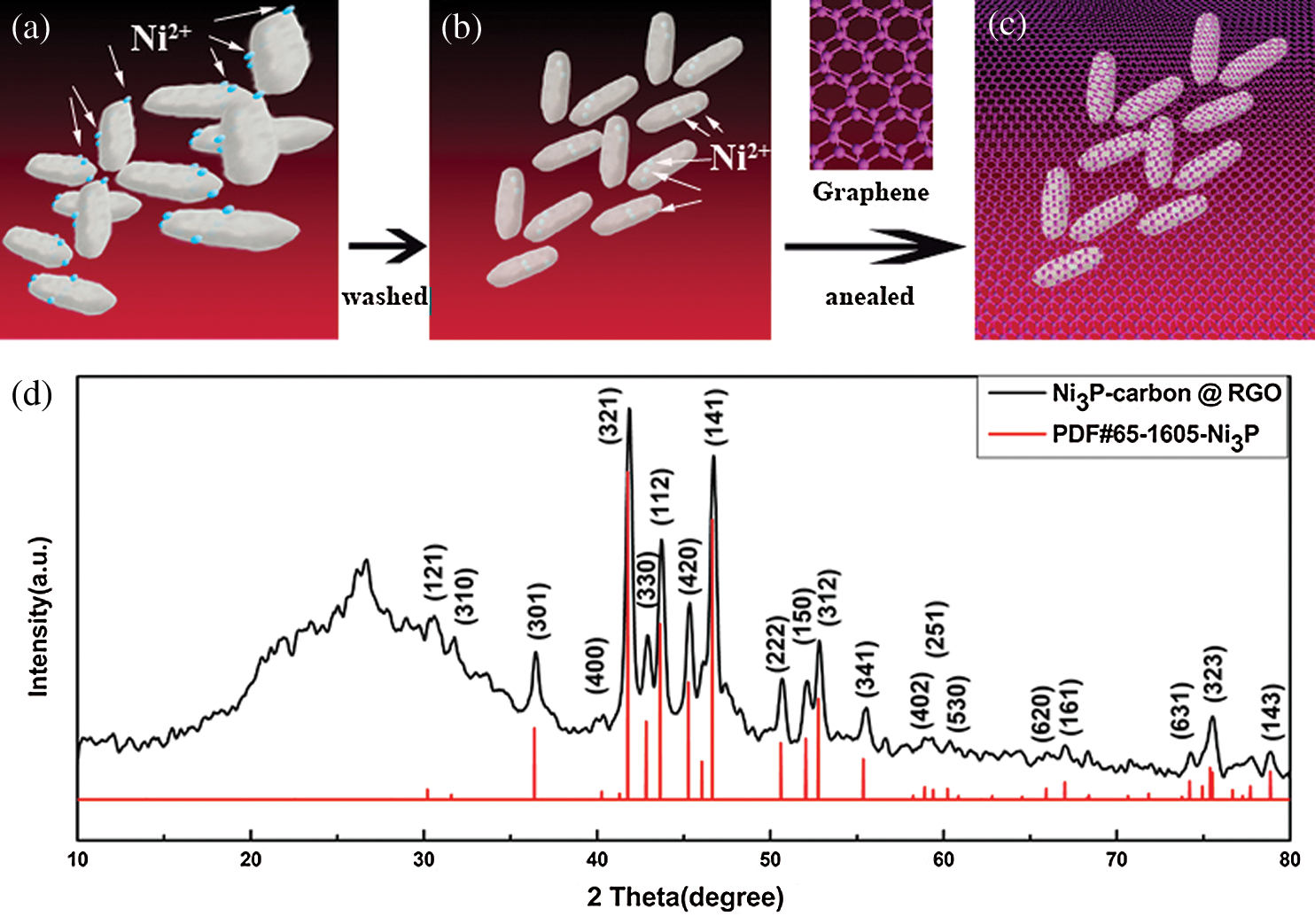
Figure 1: Schematic diagram of material synthesis process (a, b, c) and XRD pattern of the NPC @ RGO (d)
X-ray diffraction instrument was used in order to learn the components of prepared materials, the XRD pattern is shown in Fig. 1b. We can see that the most four important peaks of (321), (112), (141), (312) crystal planes are well coincident with the Ni3P (PDF#65-1605), and the other peaks which are larger than 30° also show their Ni3P characters (PDF#65-1605). From 10° to 30°, there is only an apparent peak lying at 26.32°, it should belong to carbon peak according to the PDF#65-1605. During the course of annealing, Ni ions can connect with the element in bacteria, and in an appropriate temperature, it forms Ni3P.
In order to learn the robustness of the prepared NPC @ RGO after annealing, as shown in Fig. 2a, the NPC @ RGO is bent after annealing and it still shows a complete paper without any apparent fragment, which indicates its better flexibility. During the course of preparing the NPC @ RGO, we use no binder but only GO, so the NPC @ RGO presents freestanding character. The material has the potential appliance for Wearable products. Fig. 2b shows two GPBBS whose outer surfaces are full of wrinkles. This phenomenon may be the reason of that the GPBBS have been dried. The GPBBS are about 800 nm in length and 400 nm in width. They lie in the RGO, which indicates the better conductivity. the smooth surface verifies the purity, if there are metal ions on the surface of bacteria, their surface will have particles, we cannot find particles on bacteria and RGO in Fig. 2b, it shows that metal ions on the surface of bacteria were washed away. In order to test whether the GPBBS disperse universally or not, the medium and low size SEM images of the NPC @ RGO after annealing were characterized and shown in Fig. 2c, 2d. Fig. 2c shows lots of white elliptical GPBBS lying in the RGO, evidencing our successful preparation of the NPC @ RGO. In the expanded SEM image of the NPC @ RGO after annealing, as shown in Fig. 2d, the white elliptical GPBBS become so small that we can only see plenty of white dots, which indicates that enough GPBBS were obtained. The structure that lots of GPBBS lie in RGO can insure the better conductivity during the course of charging/discharging.
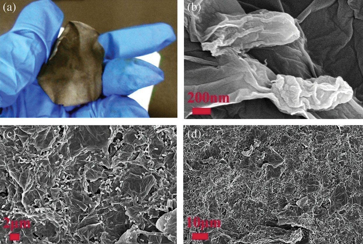
Figure 2: Photo and SEM images of the NPC @ RGO. (a) Photo of the NPC @ RGO after annealing. (b) Expanded SEM image of the NPC @ RGO after annealing. (c, d) SEM image of the NPC @ RGO after annealing
TEM and HRTEM images were applied in order to learn the inner morphology and microstructure, as shown in Fig. 3a, it displays one bacterium which is about 800 nm in length and 400 in width. The outside layer of the bacterium cytoderm is about 50–100 nm in thickness, it emerges a semitransparent structure whose main ingredient is carbon. The middle part is a hollow ellipsoid whose color is deeper than its edge, it is bacterium cavity. Because the inner wall is full of Ni3P particles, the color emerges deep. Near the inner wall, the color emerges almost black, implying it have more Ni3P particles. Fig. 3b shows a HRTEM image of GPBBS based carbon after annealing, it appears an unordered structure, this indicate it is non–graphitizing. We can see two GPBBS in Fig. 3c, there are two black blocks in the both ends, meaning that the Ni3P particles emerges crystallization, in the meantime, there can be seen a very transparent RGO under the GPBBS, indicating that the GPBBS connect RGO very well. Figs. 3d–3f also display that RGO and GPBBS connect each other very well. Fig. 3d shows a medium size TEM image of the NPC @ RGO after annealing. We can still see deep color in GPBBS endocoele, which means that Ni3P particles lie in GPBBS universally. The TEM images of NPC @ RGO after annealing (Figs. 3e, 3f) further illustrate that Ni3P particles lie in GPBBS universally, and ensure the prepared anode good performances during the course of charging/discharging. Referring to the XRD pattern, we know that our prepared materials are consisted of Ni3P and element Carbon, combine the prepared procedure and the SEM images, our prepared materials should be yolk-shell structure of Ni3P–Carbon @ RGO.
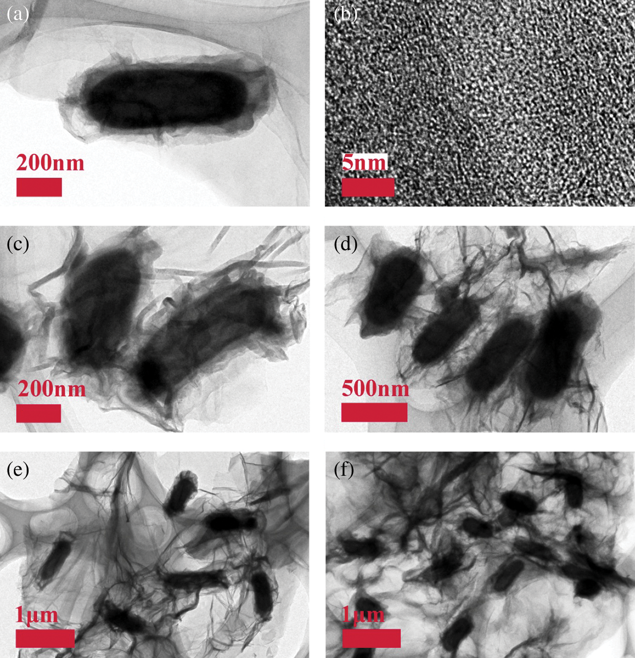
Figure 3: TEM images of the NPC @ RGO. (a) Single bacterium of the NPC @ RGO after annealing. (b) The HRTEM image of GPBBS based carbon after annealing. (c, d) The medium size TEM image of the NPC @ RGO after annealing. (e, f) The low size TEM images of the NPC @ RGO after annealing
In order to investigate the performances of the prepared NPC @ RGO, we tested the coin cells (Fig. 4).
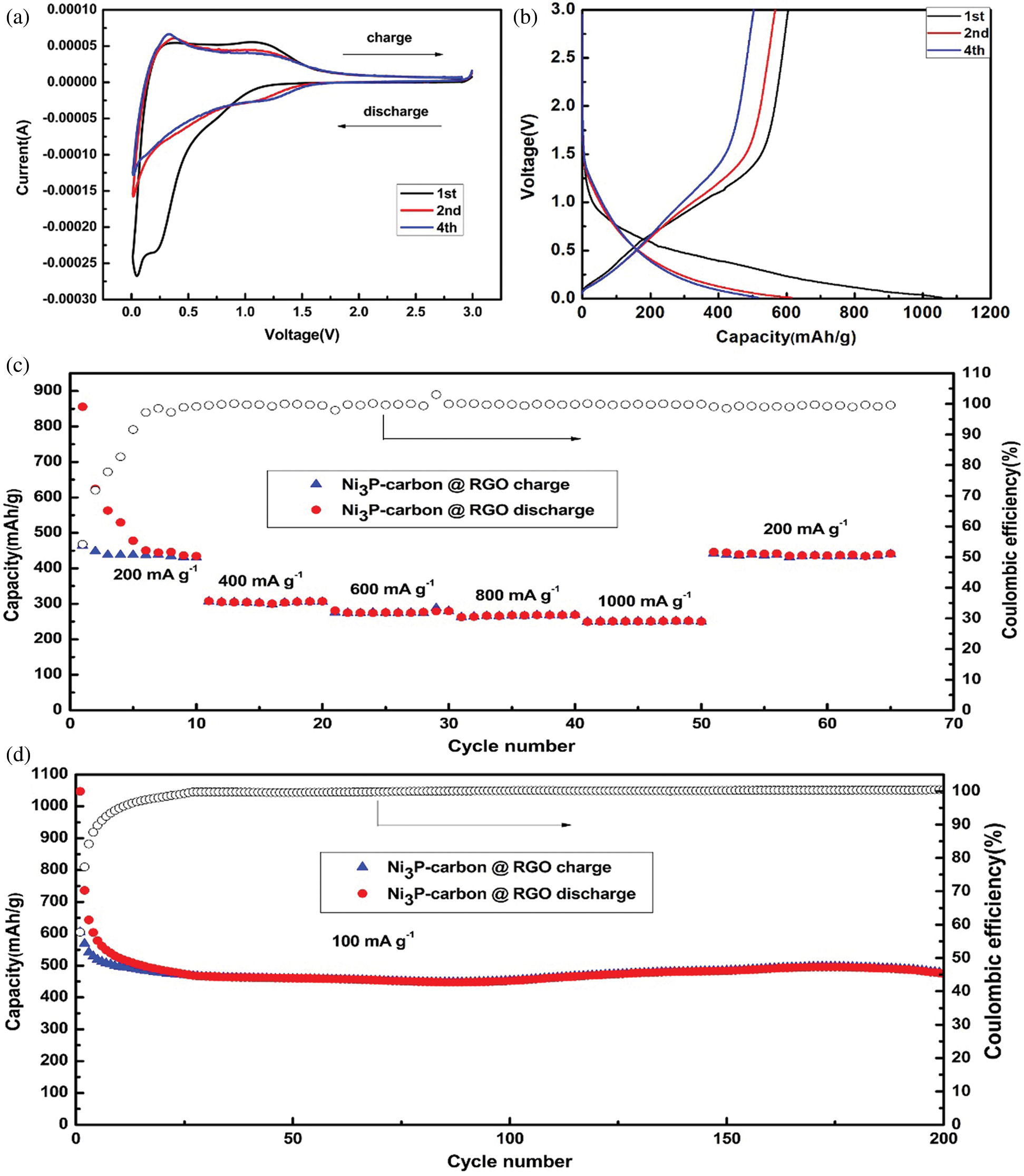
Figure 4: Electrochemical performances of the NPC @ RGO annealed at 700°C. (a) CV curves at the 1st, 2nd, 4th cycles. (b) Charging/discharging curves at a current density of 100 mA g−1 at the 1st, 2nd, 4th cycles. (c) Rate capacity and coulombic efficiency. (d) Capacity and coulombic efficiency at 100 mA g−1 current density
The cyclic voltammetry (CV) curves were measured, as shown in Fig. 4a, it presents three cycles of 1st, 2nd, 4th, it can be seen that the 1st cycle has a clear long discharging plateau arising at 0.9 V, at the same time, it presents a short discharging plateau arising at 0.2 V, it seems that the Li+ ions insert the active material, and the solid electrolyte interface forms. Accordingly, there are two charging peaks arising at 0.3 and 1.1 V, respectively, they correspond to the relative discharging plateau arising at 0.2 V and 0.9 V. it reflects the extraction of Li+ ion from active material. At the subsequent 2nd and 4th cycles, its original discharging plateau arises at 1.4 V, and the second discharging plateau arising at 0.2 V vanishes. On the contrary, the relative charging peak strength at 0.3 V increases, and then decreases later at 1.1 V, it shows that there are some irreversible reactions.
Fig. 4b shows the charging/discharging curves which the current density is 100 mA g−1 in a voltage range of 0.01–3.0 V. It displays a long sloping discharging curve at 1st cycle, its apparent plateau arises at 0.9 V, corresponding to its CV curves (see Fig. 4a). This should be attributed to the Li+ inserting the Ni3P. In this curve, the discharging plateau arising at 0.2 V is indistinct, which implies the analogous discharging speed in the whole discharging zone. The charging curve at 1st cycle displays a charging plateau whose voltage zone is 0–1.1 V, which corresponds to its CV curves (see Fig. 4a). At the 2nd, 4th cycles, its charging/discharging curve plateaus are no longer existed, which suggests its partial reversibility. In the meantime, the 2nd, 4th discharging curves overlap very well, meaning the stable discharging capacity. Combining the CV and charging/discharging curve, we consider the reacting equations as bellows:


The rate performance was tested with the current density being increased from 200–1000 mA g−1 in a voltage range of 0.01–3.0 V. Fig. 4c reveals that the first discharging capacity stabilizes at about 440 mA h g−1 after six cycles. It is noting that the discharging capacity declines a little to about 305, 275, 267, 250 mA h g−1 when the current density increases every 200 mA g-1, with the current density increasing from 400 to 1000 mA g−1, the percent rate of next later capacity than front capacity remains 90.2%, 96.4%, 93.6% discharging capacities. When the current density comes back to 200 mA g−1, it has stable discharging capacity and its discharging capacity remains at about 440 mA h g−1. This means that it has fine rate performance and is suitable for bigger current density.
In order to learn the stable performance, two hundred charging/discharging cycles were measured at 100 mA g−1 current density in a voltage range of 0.01–3.0 V. As shown in Fig. 4d, the first discharging capacity reaches 1057.0 mA h g−1, its charging capacity is 604.8, so its first coulombic efficiency reaches 57.2%. After several cycles, its charging/discharging capacities stabilize quickly, and its coulombic efficiency almost keeps 100% in the later cycles, the discharging capacity still keeps at ~475.0 mA h g−1 till 200 cycles. A high current density of 5000 mA g−1 was used to test the NPC @ RGO performance. Supplementary Fig. 1 displays that even in a high current density of 5000 mA g−1, it still keeps a better stability.
The TGA was tested in air to measure the mass percentage of NPC @ RGO, Fig. 5 shows that the mass loss of NPC @ RGO mainly occurs in 400°C - 550°C, the mass fraction remains 27.6% after 550°C, it proves that there was a better absorption of Ni+. When the temperature is over 550°C, its weight remains almost no change. Referring to our research results [23], it is clear that the carbon and RGO lost their weight from 400 to 550°C. Supposing that the capacity of Carbon @ RGO is ~275 mA h g−1 (Supplementary Fig. 2), then the capacity of Ni3P is estimated to be ~1145.58 mA h g−1.
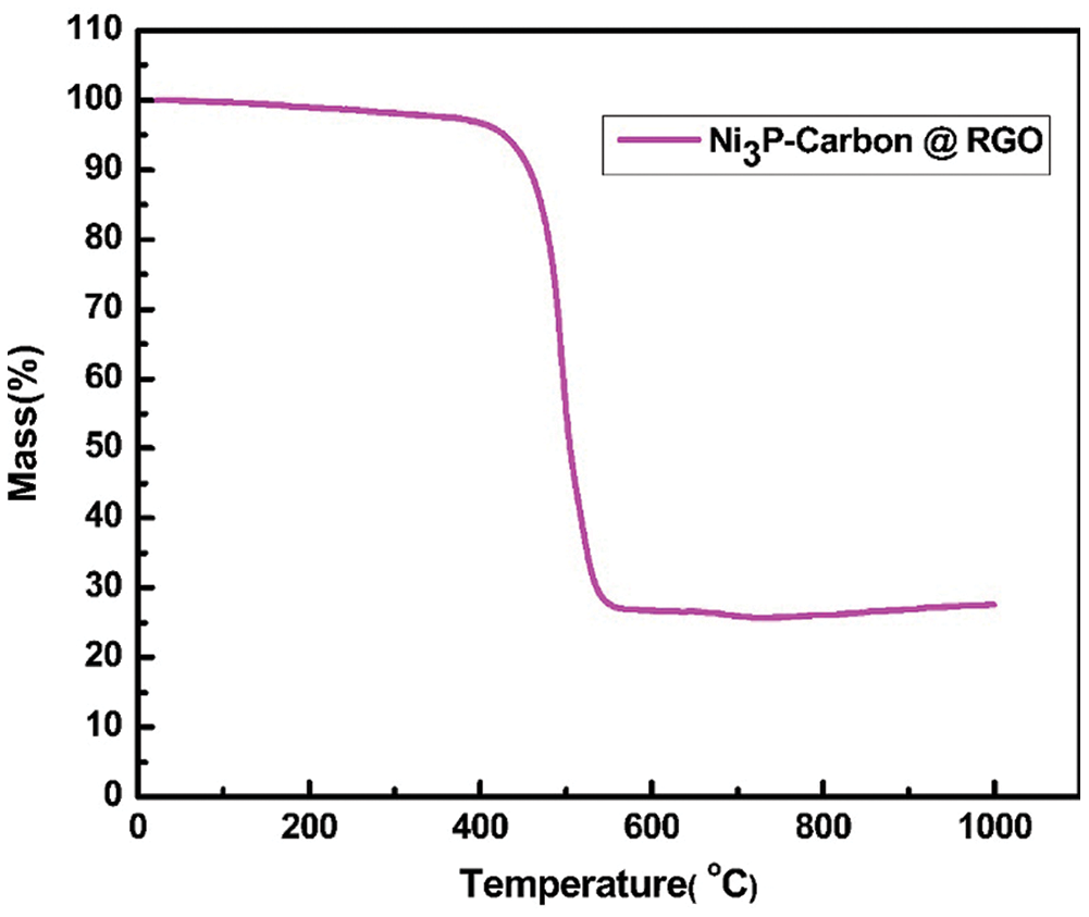
Figure 5: The TGA curve of Ni3P–carbon @ reduced graphene oxides paper (NPC @ RGO) in air
In this article, we prepared freestanding yolk-shell NPC @ RGO structure anode for LIBs, the GPBBS were cultured and used to absorb metal Ni ions, at the same time, they were also used as carbon resource to enwrap metal Ni ions. In order to discard interference element, nickel acetate was used as Ni resource. By SEM and TEM images, the metal Ni ions were successfully enwrapped by carbon via GPBBS absorption. The electrochemical performances display that the prepared freestanding yolk-shell NPC @ RGO anode have high capacity, excellent rate and stable performances. The freestanding yolk-shell NPC @ RGO structure anode indicates it is suitable for wearable device.
Funding Statement: This work was financially supported by Jiangxi Provincial Natural Science Foundation (No. 20202BABL204049), Education Department of Jiangxi Province (No. GJJ170898), Science and technology project of Yichun University (No. 2017DF001). Doctor yang received his funding from Jiangxi Provincial Natural Science Foundation (No. 20202BABL204049). Doctor Jun Zhou received his funding from Education Department of Jiangxi Province (No. GJJ170898), Science and technology project of Yichun University (No. 2017DF001).
Conflicts of Interest: The authors declare that they have no conflicts of interest to report regarding the present study.
1. Yang, Y., Zhou, J., Xu, Z., Fan, L., Lu, B. (2017). Freestanding flexible Ni12P5 in bacteria based carbon @ reduced graphene oxides paper for lithium-ion anode. Materials Letters, 207, 153–156. DOI 10.1016/j.matlet.2017.07.034. [Google Scholar] [CrossRef]
2. Yang, Y., Zhu, J., Shi, W., Zhou, J., Gong, D. et al. (2016). 3D nanoporous ZnWO4 nanoparticles with excellent electrochemical performances for supercapacitors. Materials Letters, 177, 34–38. DOI 10.1016/j.matlet.2016.04.168.
3. Bhattacharya, P., Kota, M., Suh, D., Roh, K., Park, H. (2017). Biomimetic spider-web-like composites for enhanced rate capability and cycle life of lithium ion battery anodes. Advanced Energy Materials, 7(17), 1700331. DOI 10.1002/aenm.201700331. [Google Scholar] [CrossRef]
4. Zhang, Y., Zhu, X., Xu, M., Zhou, C., Song, X. (2019). Gram-scale production of graphene powder via a quasi-physical process and its application in electrode material for lithium-ion battery. Advanced Engineering Materials, 21(2), 1800891. DOI 10.1002/adem.201800891. [Google Scholar] [CrossRef]
5. Chen, Q., Li, H., Cai, C., Yang, S., Huang, K. et al. (2013). In situ shape and phase transformation synthesis of Co3S4 nanosheet arrays for high-performance electrochemical supercapacitors. RSC Advances, 3(45), 22922. DOI 10.1039/c3ra44237c. [Google Scholar] [CrossRef]
6. Sun, Y., Tang, J., Zhang, K., Yuan, J., Li, J. et al. (2017). Comparison of reduction products from graphite oxide and graphene oxide for anode applications in lithium-ion batteries and sodium-ion batteries. Nanoscale, 9(7), 2585–2595. DOI 10.1039/C6NR07650E. [Google Scholar] [CrossRef]
7. Xie, Y., Saubanère, M., Doublet, M. (2017). Requirements for reversible extra-capacity in Li-rich layered oxides for Li-ion batteries. Energy & Environmental Science, 10(1), 266–274. DOI 10.1039/C6EE02328B.
8. Ullah, S., Ahmed, F., Badshah, A., Altaf, A., Raza, R. et al. (2014). Low-temperature Synthesis of nanocrystalline LiNi0.5Mn1.5O4 and its application as cathode material in high-power li-ion batteries. Australian Journal of Chemistry, 67(2), 289. DOI 10.1071/CH13442.
9. Li, J., Fa, W., Zhao, H., Zhu, C., Jia, H. (2019). Dendritic silver hierarchical structures for anode materials in Li ion batteries. Micro & Nano Letters, 14(8), 887–891. DOI 10.1049/mnl.2018.5648. [Google Scholar] [CrossRef]
10. Jiang, Y., Lu, C., Liu, X., Jiang, Y., Ding, Y. (2020). Lithium acetate modified PU/graphene composites as separator for advanced Li-ion batteries. Micro & Nano Letters, 15(4), 213–217. DOI 10.1049/mnl.2019.0164. [Google Scholar] [CrossRef]
11. Li, B., Jiang, N., Huang, W., Yan, H., Zuo, Y. (2018). Thermodynamic activation of charge transfer in anionic redox process for li-ion batteries. Advanced Functional Materials, 28(4), 1704864. DOI 10.1002/adfm.201704864.
12. Huang, H., Gao, S., Wu, A., Cheng, K., Li, X. et al. (2017). Fe3N constrained inside C nanocages as an anode for Li-ion batteries through post-synthesis nitridation. Nano Energy, 31, 74–83. DOI 10.1016/j.nanoen.2016.10.059.
13. Zou, S., Zhang, Y., Xue, C., Wei, H., Chen, H. et al. (2019). Electrochemical characteristics of pure and Al, Mn-doped Li4Ti5O12 as high-performance anode materials for li-ion batteries. Chemistry Letters, 48(7), 708–711. DOI 10.1246/cl.190154. [Google Scholar] [CrossRef]
14. Lyu, F., Yu, S., Li, M., Wang, Z., Nan, B. et al. (2017). Supramolecular hydrogel directed self-assembly of C- and N-doped hollow CuO as high-performance anode materials for Li-ion batteries. Chemical Communications, 53(13), 2138–2141. DOI 10.1039/C6CC09702B. [Google Scholar] [CrossRef]
15. Niu, J., Shao, R., Liang, J., Dou, M., Li, Z. et al. (2017). Biomass-derived mesopore-dominant porous carbons with large specific surface area and high defect density as high performance electrode materials for Li-ion batteries and supercapacitors. Nano Energy, 36, 322–330. DOI 10.1016/j.nanoen.2017.04.042. [Google Scholar] [CrossRef]
16. Liu, J., Li, X., Huang, J., Li, J., Zhou, P. et al. (2017). Three-dimensional graphene-based nanocomposites for high energy density Li-ion batteries. Journal of Materials Chemistry A, 5(13), 5977–5994. DOI 10.1039/C7TA00448F. [Google Scholar] [CrossRef]
17. Ni, S., Huang, P., Chao, D., Yuan, G., Zhang, L. et al. (2017). Amorphous GaN@Cu freestanding electrode for high-performance li-ion batteries. Advanced Functional Materials, 27(35), 1701808. DOI 10.1002/adfm.201701808.
18. Yu, X., Wang, B., Gong, D., Xu, Z., Lu, B. (2017). Graphene nanoribbons on highly porous 3D graphene for high-capacity and ultrastable al-ion batteries. Advanced Materials, 29(4), 1604118. DOI 10.1002/adma.201604118. [Google Scholar] [CrossRef]
19. McNulty, D., Geaney, H., Buckley, D., O’Dwyer, C. (2018). High capacity binder-free nanocrystalline GeO2 inverse opal anodes for Li-ion batteries with long cycle life and stable cell voltage. Nano Energy, 43, 11–21. DOI 10.1016/j.nanoen.2017.11.007. [Google Scholar] [CrossRef]
20. Wang, H., Pan, Q., Wu, Q., Zhang, X., Huang, Y. et al. (2017). Ultrasmall MoS2 embedded in carbon nanosheets-coated Sn/SnOx as anode material for high-rate and long life Li-ion batteries. Journal of Materials Chemistry A, 5(9), 4576–4582. DOI 10.1039/C6TA10932B.
21. Hao, Z., Yuan, L., Li, Z., Liu, J., Xiang, J. et al. (2016). High performance lithium-sulfur batteries with a facile and effective dual functional separator. Electrochimica Acta, 200, 197–203. DOI 10.1016/j.electacta.2016.03.166. [Google Scholar] [CrossRef]
22. Yang, D., Zhou, Y., Rui, X., Zhu, J., Lu, Z. et al. (2013). Fe3O4 nanoparticle chains with N-doped carbon coating: magnetotactic bacteria assisted synthesis and high-rate lithium storage. RSC Advances, 3(35), 14960. DOI 10.1039/c3ra42116c. [Google Scholar] [CrossRef]
23. Yang, Y., Wang, B., Zhu, J., Zhou, J., Xu, Z. et al. (2016). Bacteria absorption-based Mn2P2O7-Carbon@reduced graphene oxides for high-performance lithium-ion battery anodes. ACS Nano, 10(5), 5516–5524. DOI 10.1021/acsnano.6b02036. [Google Scholar] [CrossRef]
24. Deng, Z., Jiang, H., Hu, Y., Liu, Y., Zhang, L. et al. (2017). 3D ordered macroporous MoS2 @C nanostructure for flexible li-ion batteries. Advanced Materials, 29, 1521–4095. DOI 10.1002/adma.201603020. [Google Scholar] [CrossRef]
25. Liao, Q., Li, S., Cui, H., Wang, C. (2017). Vertically-aligned graphene@Mn3O4 nanosheets for a high-performance flexible all-solid-state symmetric supercapacitor. Journal of Materials Chemistry A, 4(22), 8830–8836. DOI 10.1039/C6TA02258H. [Google Scholar] [CrossRef]
Appendix
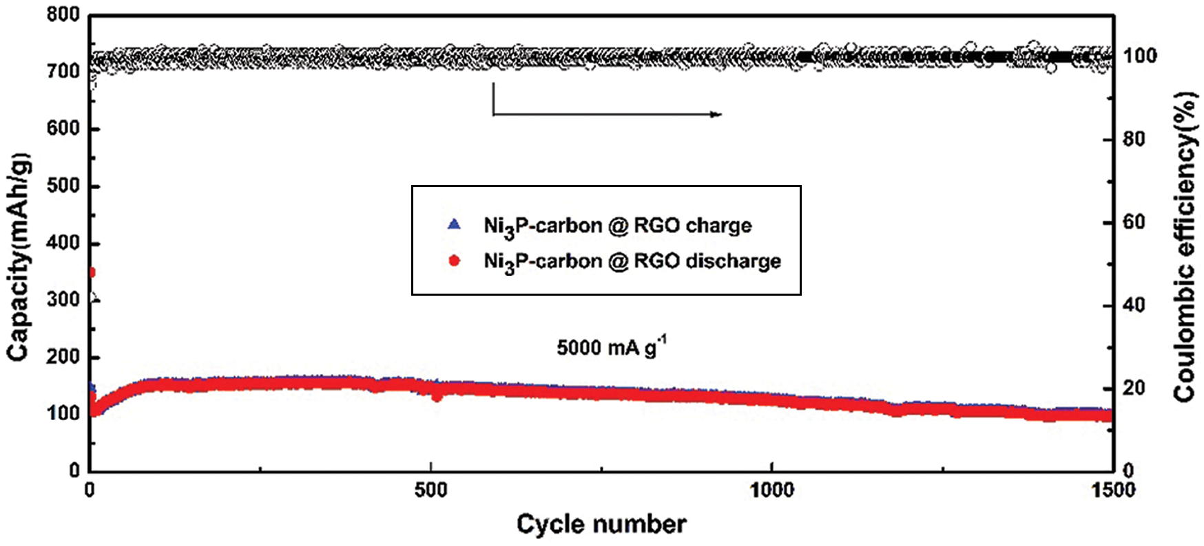
Supplementary Figure 1: Capacity and coulombic efficiency at 5000 mA g−1 current density
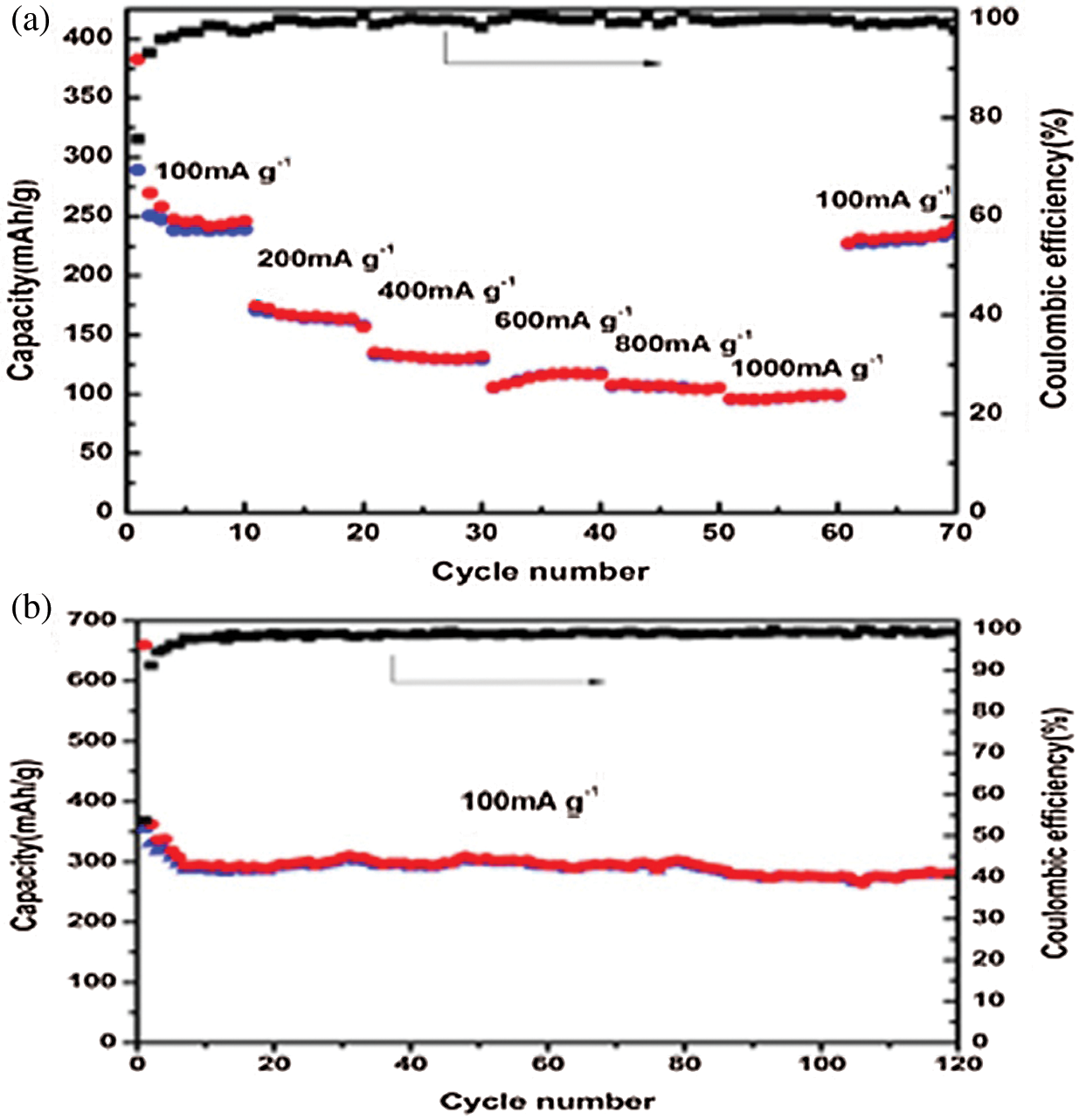
Supplementary Figure 2: (a) Rate capacity and coulombic efficiency of pure bacteria-based carbon @ RGO. (b) Capacity and coulombic efficiency for 120 cycles at 100 mA g−1 current density of pure bacteria-based carbon@RGO
 | This work is licensed under a Creative Commons Attribution 4.0 International License, which permits unrestricted use, distribution, and reproduction in any medium, provided the original work is properly cited. |