| Journal of Renewable Materials |
DOI: 10.32604/jrm.2021.014138
ARTICLE
Effect of Plastocene Embedment in the Microperforated Plate on Its Acoustic Performance
1Ministry of Education Key Laboratory for Cross-Scale Micro and Nano Manufacturing, Changchun University of Science and Technology, Changchun, 130022, China
2Key Laboratory of Bionic Engineering (Ministry of Education), Jilin University, Changchun, 130025, China
*Corresponding Author: Yonghua Wang. Email: yonghua@cust.edu.cn
Received: 02 September 2020; Accepted: 13 October 2020
Abstract: Noise pollution is one of the contemporary environmental pollution, which seriously damages people’s green and healthy life. In order to further improve the low frequency sound absorption performance of microperforated panel (MPP), a new plastocene coupled microperforated plate (PCMPP) is proposed. The acoustic properties of PCMPP with different apertures and perforation ratio were measured by transfer function method and compared with that of conventional MPPs. It is found that when the aperture was 0.8 mm, the peak value of sound absorption coefficient of PCMPP decreased by 150 Hz compared with MPP. In a certain range, PCMPP with larger apertures showed a greater influence on sound absorption property in low frequency. In addition, higher perforation ratio led to a greater PCMPP bandwidth of sound absorption. On the other hand, the effect of PCMPP with aperture of 0.2 mm on the performance of MPP was reduced, which could be compensated by increasing the perforation ratio. Furthermore, we found that the effect of aperture, perforation ratio and cavity on the sound absorption performance of PCMPP was consistent with that of ideal rigid MPP. The step cooling curve showed that the plastocene began to soften at about 50°C, representing a great potential for a non-high temperature work environment.
Keywords: Noise pollution; plastocene coupled microperforated panel; transfer function method; sound absorption coefficient
Noise pollution is one of the four major modern pollutions, which will cause great harm to human body and mind. Therefore, reducing noise pollution has become a research hotspot. However, as compared to middle and high frequencies, it is hard to reduce the adverse impact of low-frequency noise due to its longer wavelength and higher penetrating power, which makes the acoustic wave efficiently propagation. Therefore, how to reduce the low frequency noise has become a mainstream in current research.
Since academician Maa Dayou put forward the sound absorption theory of MPP [1–3], MPPs have been widely used in large projects such as meeting rooms, concert halls, natatorium, gymnasium and road sound barrier [4–5]. On the basis of Maa’s theory, scholars have made deep research on the material optimization and structural design of MPP. Mosa et al. [6] proposed a two-layer MPP with uneven perforation and multiple cavities of different depths behind it, to obtain a wider sound absorption coefficient. Pedro et al. [7] studied the three-layer MPP to broaden the sound absorption frequency. Bucciarelli et al. [8] studied the relationship between the sound absorption mechanism of multi-layer MPP and the geometric parameters of the sound absorption material. The results showed that five-layer MPP absorber could ensure a high absorption rate within the frequency range of 400–2000 Hz. Wang et al. [9] studied the MPP absorber array composed of four parallel-arranged MPP absorbers with different cavity depths. And found that at oblique incidence, the equivalent acoustic impedance of the MPP decreases as the incidence angle increases, which changes the acoustic impedance matching conditions in the MPP absorber array. Wang et al. [10] explored the acoustic performance when the conventionally flat perforated panel is replaced with a corrugated one, and the normal incidence, oblique incidence and diffuse field acoustic performance were simulated with three-dimensional finite element model and the measured normal incidence absorption coefficients compare well with the numerical predictions, Results show that the absorption characteristics of corrugated MPPA can be very different from conventional flat MPPA and the corrugation depth is found to be more influential than the corrugation pitch on the sound absorption. Some scholars increased the structural complexity by adding porous sound absorbing materials to the cavity to extend the absorption bandwidth [11–13].
Shen et al. [14] developed a low-frequency sound absorber by optimizing the combined structure of porous metal and MPP. Zhao et al. [15,16] arranged a parallel mechanical impedance structure in the cavity of the MPP to form a composite material structure with the quality of mechanical impedance of 6.4 g, which proved the feasibility of the composite material structure to improve the low-frequency sound absorption performance. Li et al. [17] studied MPPs of three different flexible materials based on polyvinylchloride (PVC), polyethylene terephthalate (PET), and polyimide (PI). They found that flexible MPP made of PET exhibited the best acoustic absorption properties. Compared with the traditional rigid MPP, the absorption peak frequency of flexible MPP moves towards low frequency. Zhang [18] proposed that based on Helmholtz resonator, the rigid bottleneck was replaced by a flexible tube to form a low-frequency broadband resonant sound absorption structure. Yang et al. [19] studied the coupling relationship between different types of backing cavity and MPP, and the results showed that the presence of backing cavity mode not only affected the acoustic characteristics of MPP, but also deteriorated the sound absorption performance of MPP. Li et al. [20,21] established models of typical MPP with different amounts of metal fibres by using finite element method. They studied the sound absorption coefficient, acoustic impedance and spatial distribution of normal particle velocity in the micro holes of two MPPs. Xu et al. [22] drilled different amounts of copper fibres into the holes of MPP to study the effect of the number of copper fibres on the sound absorption performance of thin MPP. Zhang et al. [23] studied the sound absorption performance of flexible PVC-MPP, and found that the resonance peak of the absorber of the flexible MPP shifted to the low frequency. In order to further improve the sound absorption performance of flexible MPPs. Ren et al. [24] proposed a new kind of porous acoustic absorption metamaterials, which combined the main plate of MPPs with local resonators attached to the sub-wavelength scale.
Based on the above research, it is found that inserting flexible or fibrous materials into the holes and increasing the flexibility of the MPPs can improve the sound absorption performance of MPP in the middle and low frequency. But the flexible MPPs show low stiffness and narrow adaptive range. In this paper, a new method of coupling MPP and flexible material was proposed to improve its sound absorption at low frequencies. It is proposed to fill part of the holes of rigid MPP with flexible plastocene, expecting the new type of PCMPP to effectively improve the low-frequency sound absorption performance under the condition of certain stiffness.
According to the calculation of sound absorption bandwidth in the classical MPP theory [1–3], when 1 < k < 10, a wide sound absorption bandwidth can be achieved without using other sound absorption materials, and k is the constant of micro-perforated plate:

The relative acoustic impedance of MPP is defined as:

The relative acoustic resistance and relative acoustic reactance of MPP is defined as:


where d, t, σ and η represent the aperture, plate thickness, perforation ratio and viscosity of air motion respectively.
When the air backed cavity D is included, the relative acoustic impedance of back cavity is defined as:

Therefore, the relative acoustic impedance of the whole structure is defined as:

When the sound wave is incident vertically, the sound absorption coefficient of MPP is defined as:

A PCMPP is composed of a sheet metal with large number of holes and sesames sized plastocene. Due to the addition of plastocene to MPP changes the stiffness and density, the amplitude and natural frequency of the sheet metal also be changed. According to the theory of flexible MPPs [25–26], we found that the impedance of the flexible PCMPP includes two parts: Perforation impedance and the equivalent panel impedance related to the effect of the flexural vibration of the panel. As show in Fig. 1, the system can be analogous to an electrical circuit. Thus, the two parts are connected in parallel as the overall impedance of the PCMPP.
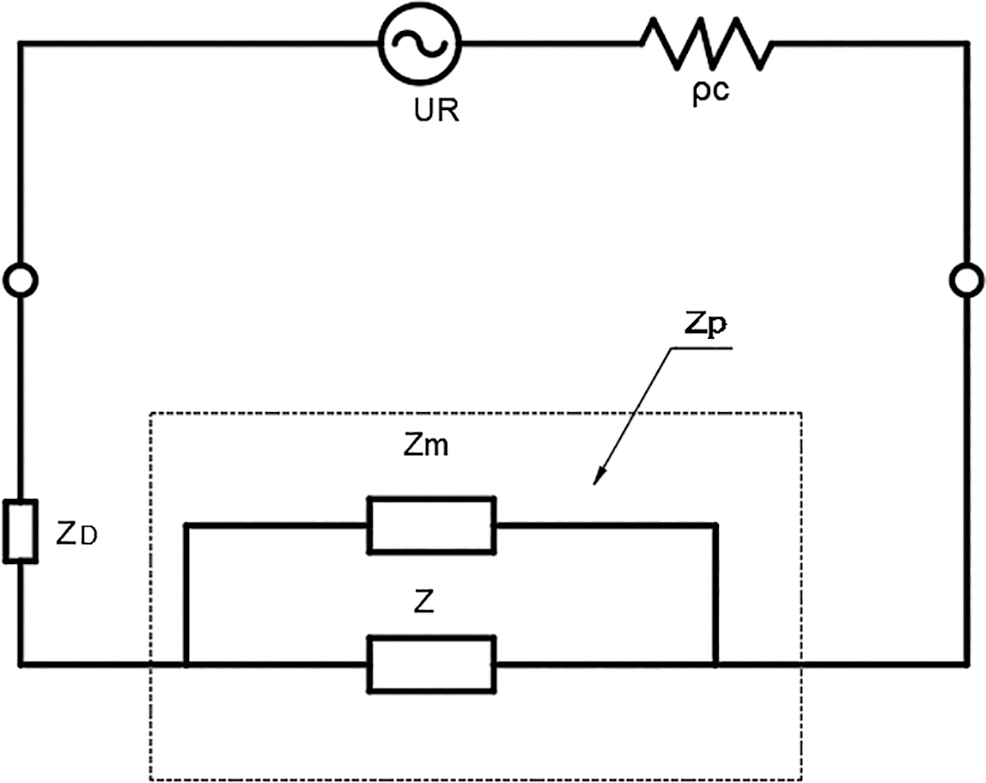
Figure 1: Electro-acoustical equivalent circuit model for the PCMPP absorber
The forces acting on the panel surfaces are due to the external sound pressure p and internal pressure pD. Thus, for a thin PCMPP, the governing equation for flexural vibration is:

where w is the displacement of the panel,  is known as the biharmonic operator,
  is the mass per unit area of the PCMPP,
  represents the bending stiffness of the plate. E, v, t are Young’s modulus, Poisson’s ratio, and thickness of the panel, respectively. The velocity of the panel can be expressed as:

Considering the panel displacement, w can be expressed by the normal mode expansions, the velocity of the panel can be given by:

Taking the integration over the PCMPP area, and using the orthogonal properties of the modal shape functions, we can obtain:

where  ,
,  is the modal impedance,
  is the mode damping ratio.
  is the resonant frequency. S is the area of the panel.
  and
and  are the modal velocity amplitude and normal mode shape function of the (m, n) mode, respectively.

where

The average panel velocity  and average velocity
  can be given by:


where  is the impedance of the panel.


Substituting Eq. (15) into Eq. (14) to eliminate  gives:

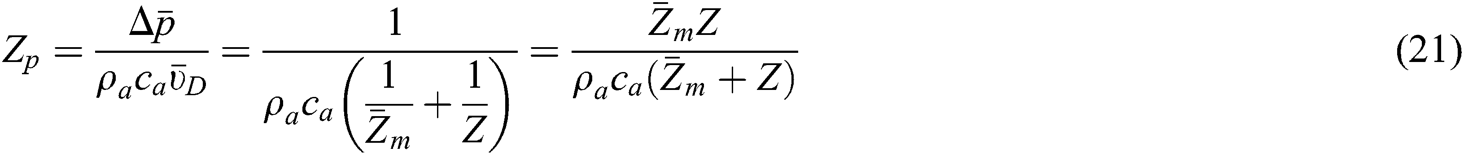
Substituting Eq. (19) into Eq. (16) to eliminate  gives:

The acoustic impedance of the MPP can be defined as:

where

When the sound wave is incident vertically, the sound absorption coefficient of the PCMPP is defined as:

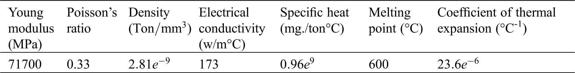
PCMPP is composed of MPP (Fig. 2a) and plastocene (Fig. 2b). In this study, MPP was made of metal materials, 7075 aluminium alloy, and plastocene with high hardness were selected, as shown in Fig. 2. 7075 aluminum alloy is a kind of cold-treated forged aluminum alloy which has high strength and good fatigue resistance, is widely used in aviation, navigation, weapons, sports and other fields. The chemical composition and material properties of 7075 aluminium alloy are shown in Tabs. 1 and 2, respectively.
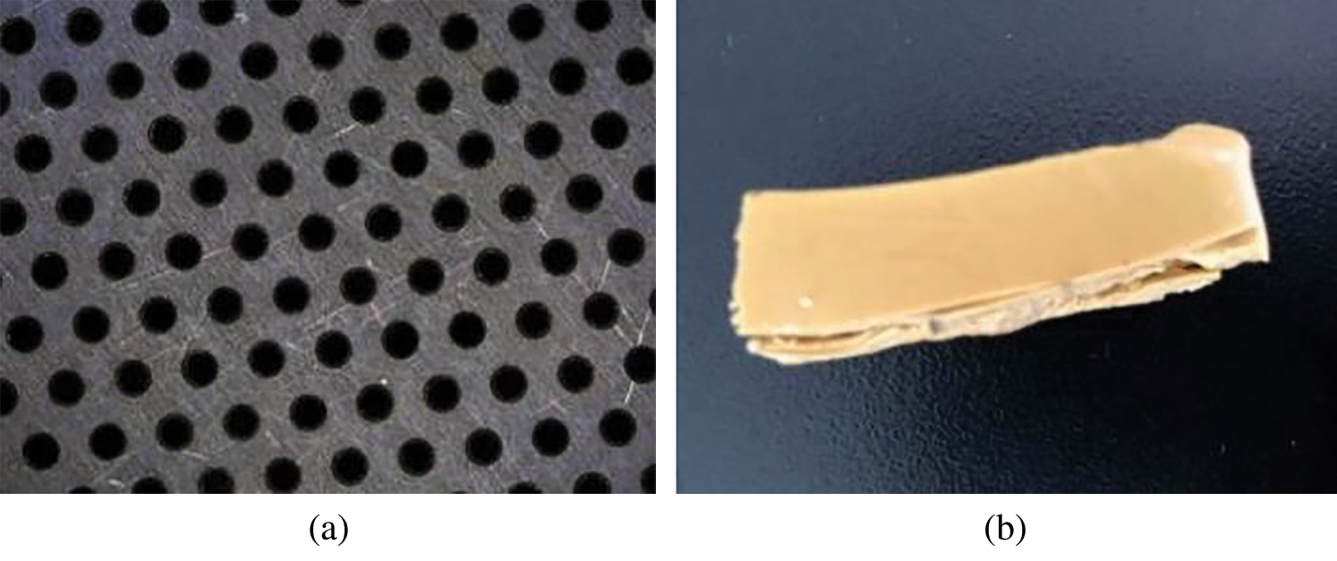
Figure 2: Punched-plate and high hardness plastocene cutting block
Table 1: Chemical composition of 7075 aluminum alloy

Table 2: Properties of 7075 aluminium alloy
Plastocene can be recycled and stored for a long period of time without deterioration, which is usually used in handicraft, plastic moulding and sculpture. It consists of 60% industrial clay (talc powder), 30% flexible binder and 10% solid binder (paraffin or vaseline). Plastocene is very sensitive to temperature, and low hardness plastocene can be kneaded to change its shape at hand temperature while high hardness one needs to be melted by heating equipment before changing its shape. Moreover, it has the same volume both in solid and liquid. The melting point was tested by temperature-controlled water tank, and the results are shown in Fig. 3a. It can be seen that the plastocene showed an obvious tendency to melt at 63°C and became viscous liquid at 76°C. In addition, its melting point was tested by KWL-10 elevated and cooled electric furnace. The step-cooling curve is shown in Fig. 3b. It indicates that there was no obvious inflection point in the curve because plastocene was not a metal or alloy. From the curvature of the line, when the temperature was below 112°C, the plastocene liquid became more viscous and solidified at about 50°C.
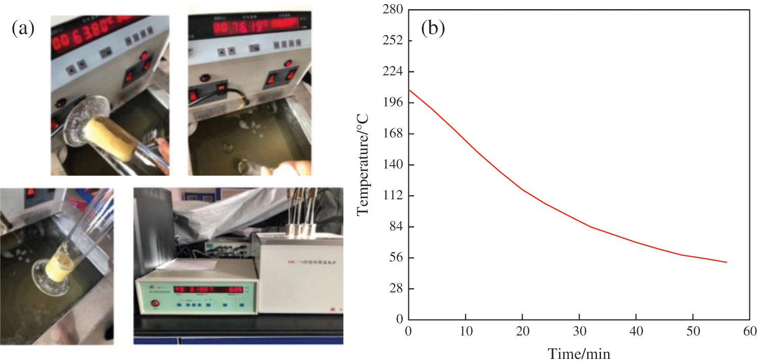
Figure 3: Observing the melting point of plastocene with temperature-controlled water tank (a) and electric furnace and step cooling curve (b)
3.2 Preparation of MPP and PCMPP
There are five steps in the preparation of PCMPP. Firstly, the MPP is processed and then put into the melted plastocene. After the plastocene solidifies, the plastocene on the surface of MPP is scraped off. Finally, according to the experimental requirements, fine needles were used to discharge the plastocene in the specified holes, as shown in the Fig. 4. The following is the detailed preparation process of PCMPP.
Step 1: Conventional MPP (Fig. 4a) are processed by Haas vertical CNC machining center. Tungsten steel bits with different diameters are selected for the drill bit. During processing, the spindle speed is set to 6000 r/min, the feed is 100 mm/min, and the cutting depth is 0.03 mm. To prepare PCMPP, the MPP was first cut into a circular plate with a diameter of 100 mm and a thickness of 0.5 mm, and the holes on the plate were evenly arranged in an equilateral triangle. Step 2: Then a hot air gun was used to heat the plastocene to the molten state (Fig. 4b) and then place it into a container. Step 3: Subsequently, the MPP was dipped into the plastocene (Fig. 4c), allowing all the holes of the MPP to be filled with plastocene before taking it out. Step 4: Then the plastocene sit on the surface was scraped off after standing in the air for one minute (Fig. 4d). Step 5: Finally, according to the experimental requirements, fine needles (Fig. 4e) were used to discharge the plastocene in the specified holes. The details of PCMPP are shown in Fig. 5b.
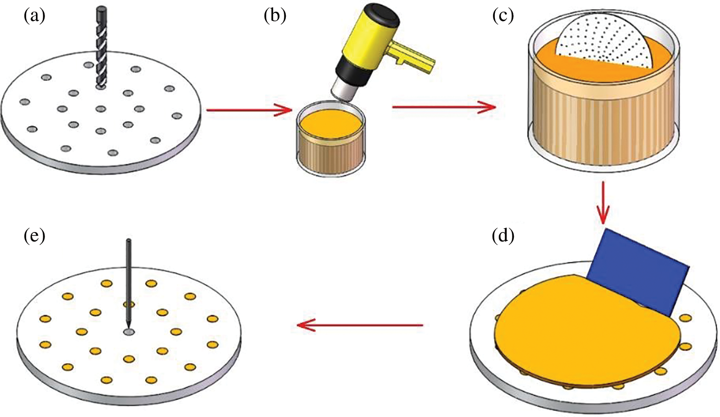
Figure 4: The processing of PCMPP
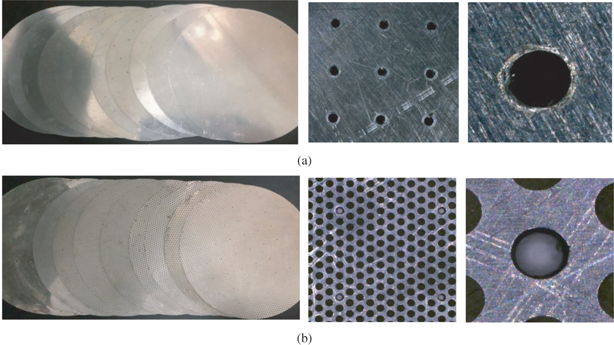
Figure 5: Two groups of experimental samples prepared (a) MPP. (b) PCMPP
In this study, impedance tubes were used to measure the normal incidence sound absorption performance by transfer function method [27]. The testing equipment is SW series impedance tube and four-channel acoustic analyser of BSWA Technology Co., Ltd. and the equipment is displayed in Fig. 6a. The sound absorption for all PCMPPs were experimentally measured by utilizing two-microphone impedance tube method according to ISO10534-2:1998(E) standard [28] and the diameter of the impedance tube used in this paper is 100 mm. As is show in Fig. 6c, tube type SW420 was used to test sound absorption coefficient, which includes SW100-L (length 850 mm) and SW100-S (length 235 mm). The distance between microphone 0 and 2 is 300 mm and the left surface of the PCMPP is 50 mm away from microphone 2. The experiment was conducted in a laboratory with the ambient temperature of (25 ± 2)°C and the relative humidity was (50 ± 5)%. The speed of sound was 343 m/s and the density of air was 1.2 kg/m3. The sampling frequency of dSPACE was set at 51200 Hz, which is high enough to avoid the aliasing problem.
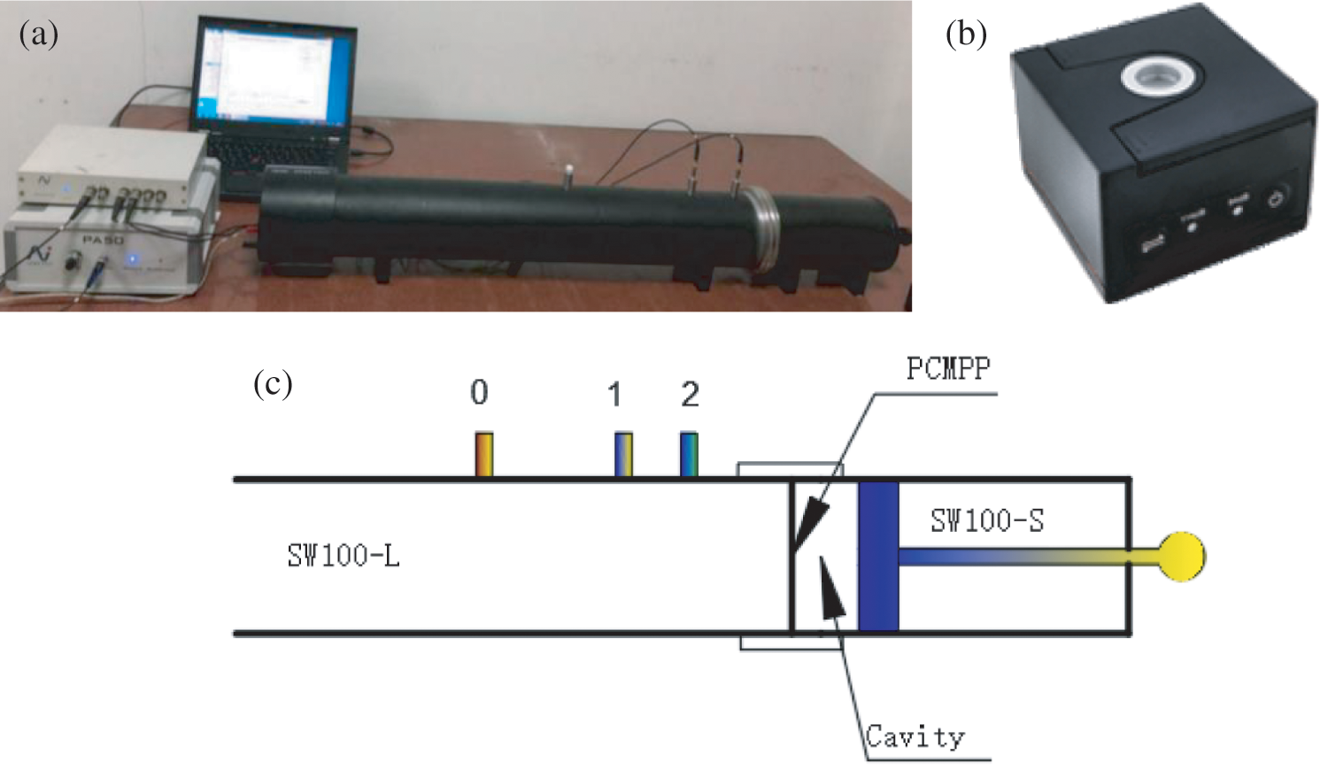
Figure 6: (a) Impedance tubes. (b) Sound level calibrator. (c) Impedance tubes schematic diagram
The PCMPP or MPP was slowly pushed and fitted within the impedance tube. L shape ruler was used as an indicator and reference to ensure that the sample was always flat and perpendicular to the horizontal axis of the impedance tube. In this method, random sound signal was generated by a loudspeaker at one end of the impedance tube. Fig. 6b shows a BSWA sound level calibrator (CA114) which is used to calibrate the microphone according to ANSI S1.40-1984(R1997) standard before the test. The impedance tube applied the complex acoustic transfer function H12 for two microphones in calculating the sound absorption coefficient  for all the PCMPPs [29–31]. Microphone 0 and microphone 2 were used to test
  within frequency range of 68–500 Hz. Microphone 1 and 2 was used to test
  within frequency range of 200–1600 Hz. Then the VA-Lab system is used to record the sound absorption coefficient results of the two tests and fit them to be a whole sound absorption curve in frequency range of 68–1600 Hz.
4 Sound Absorption Performance of PCMPP
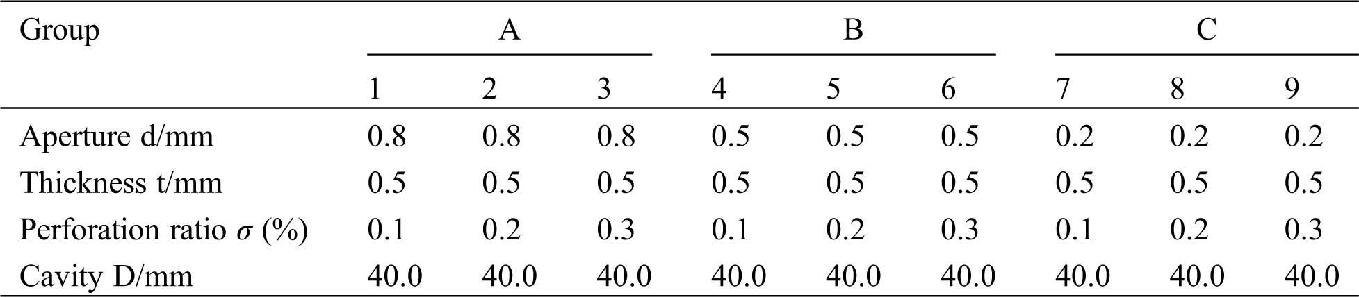
In order to study the effect of PCMPP on sound absorption performance, three groups of experiments for MPPs and PCMPPs were established, and the experimental parameters are as displayed in Tab. 3.
Table 3: Experimental design to verify the sound absorption performance of PCMPP
4.1 The Experimental Results of Group A
The experimental results are shown in Fig. 7. By comparing the three groups of MPPs and PCMPPs with different parameters, it is found that the sound absorption performance of the PCMPP was consistent with that of the conventional MPP. However, the sound absorption peak of PCMPP moved to the low frequency by 100–150 Hz approximately. The peak value showed little change and was within the range of reasonable errors of the test. Therefore, the low-frequency sound absorption performance of PCMPP was significantly improved.
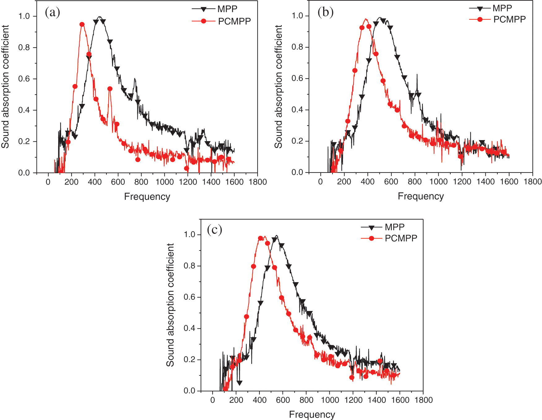
Figure 7: Sound absorption coefficients of PCMPP and MPP for Group A with aperture of 0.8 mm
4.2 The Experimental Results of Group B
The experimental results are shown in Fig. 8. When the perforation ratio was 0.1%, 0.2% and 0.3%, the sound absorption peak of the PCMPP moved to the low frequency by about 100–120 Hz. When the perforation ratio was 0.1%, 0.2%, the absorption peak value of PCMPP slightly decreased. However, the absorption peak of PCMPP increased by 0.1, when the perforation ratio was 0.3%. On the whole, the addition of plastocene improves the low-frequency sound absorption performance of MPP, especially significantly under 400 Hz.
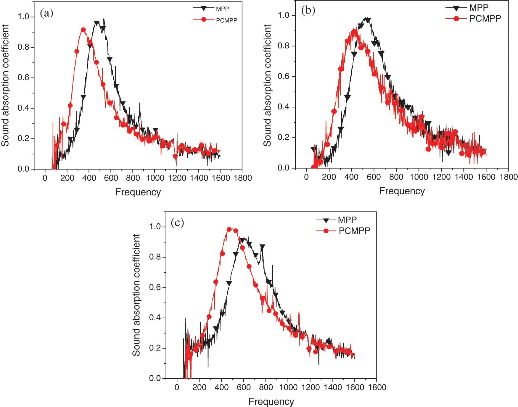
Figure 8: Sound absorption coefficients of PCMPP and MPP for group B with aperture of 0.5 mm
4.3 Experimental Results of Group C
The experimental results are shown in Fig. 9. The results showed a less difference between conventional MPP and PCMPP, especially for perforation ratio of 0.1% and 0.2%. In case of perforation of 0.3%, the absorption peak of PCMPP moved to low frequency by about 50 Hz, and the effective sound absorption bandwidth was also increased.
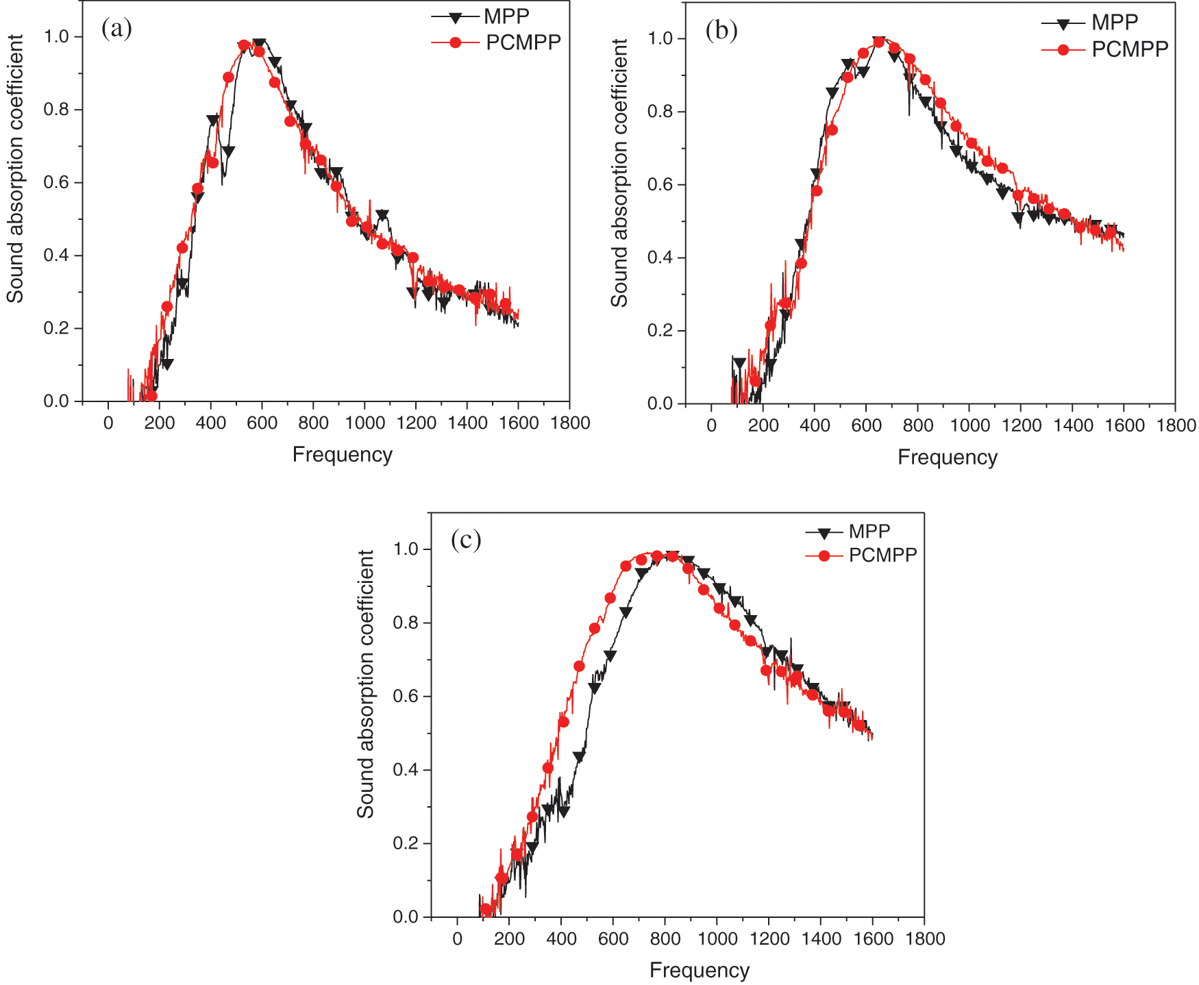
Figure 9: Sound absorption coefficients of PCMPP and MPP for group C with aperture of 0.2 mm
By longitudinally comparing the sound absorption performance curves of the three Groups A, B, and C, we found that, on the whole, the peak value of sound absorption of PCMPP all moved towards low frequency, but the movement amplitude became smaller and smaller as the aperture became smaller, until the aperture is 0.2 mm, the peak position is almost unchanged. And the peak value of sound absorption for PCMPP changed little or slightly decreased. We speculated that due to the increase in the aperture and the degree of plastocene filling, the density and stiffness of the entire PCMPP have changed compared with that of the MPP. Thus, the modal damping of PCMPP is increased, which makes its flexible characteristics more prominent [24]. The sound absorption performance of MPP is improved in a certain range.
5 Parameter Optimization of PCMPP
Hu et al. [32] explored the effect of structural parameters such as perforation ratio, aperture and back cavity on the performance of rigid MPP. In order to understand the sound absorption mechanism of PCMPP, the effect of above three parameters on sound absorption performance of PCMPP were investigated here. It is found that the variation trend of sound absorption coefficient of the PCMPP was consistent with that of the conventional rigid MPP, conforming to the theory of Maa’s MPP.
5.1 Effect of Perforation Ratio on Sound Absorption Coefficient
In order to study the effect of perforation ratio on the sound absorption performance of PCMPP, three groups of PCMPPs with different apertures were designed. The specific parameters are shown in the Tab. 4.
Table 4: Experimental scheme for the effect of perforation ratio on  of PCMPP
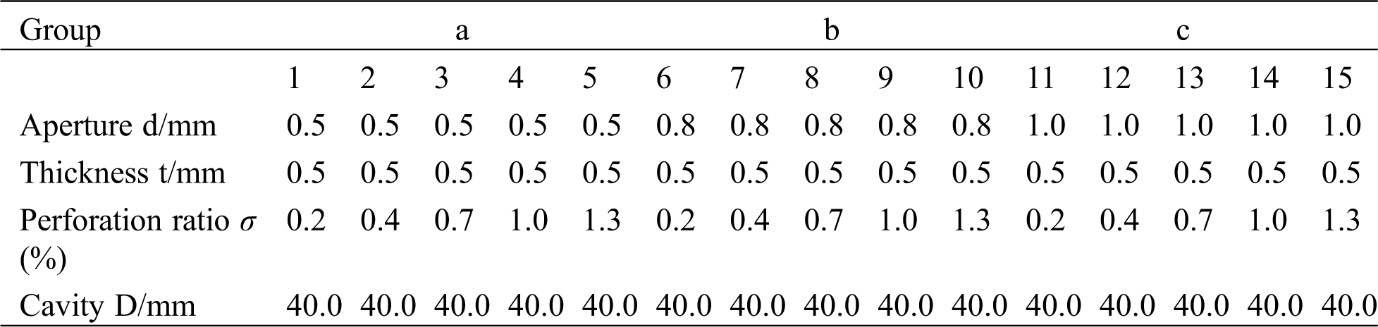
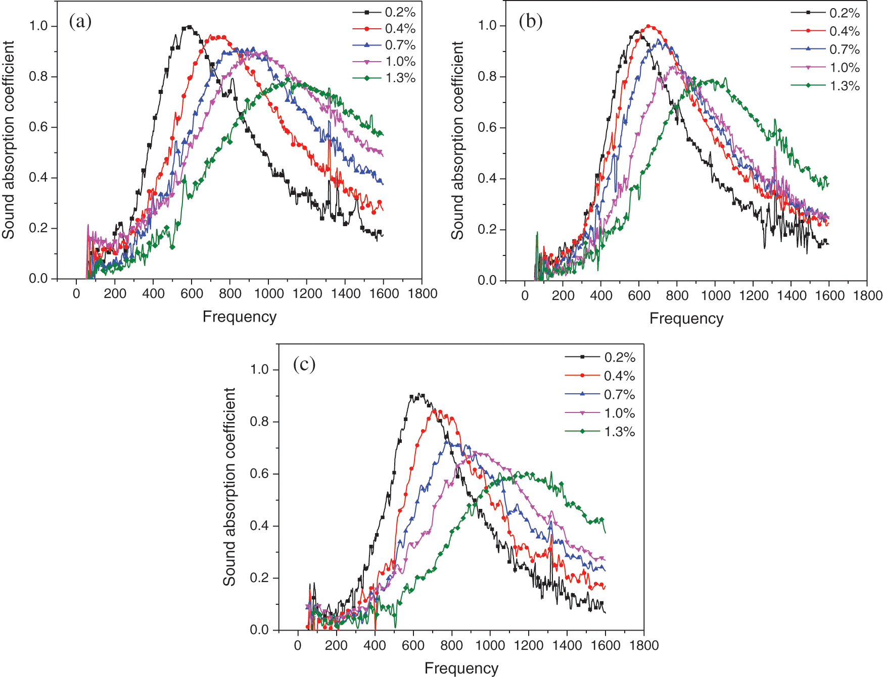
Figure 10: Experiment results of the effect of perforation ratio on absorption coefficients of PCMPP
By comparing the three groups of curves, it can be found that with the increase of porosity from 0.2% to 1.3%, the sound absorption peak gradually moves to high frequency, and the absorption peak gradually decreases. However, the sound absorption bandwidth shows a trend of broadening, and the overall sound absorption performance of low frequency significantly decreases. Especially when the aperture is 0.5 and 1.0, the variation trend and amplitude are more obvious. Specifically, for aperture 0.5 group, sound absorption peaks decreased from around 1.0 at 600 Hz to 0.77 at 1100 Hz. In the aperture group of 0.8, the sound absorption peak decreased from 0.97 at 600 Hz to 0.78 at 1000 Hz. and the sound absorption coefficient of perforated ratio is 0.4 in our group the sound absorption peak was 1.0 at 640 Hz. In the aperture group of 1.0, sound absorption peaks decreased from 0.9 at 600 Hz to 0.53 at 1170 Hz, and also show that the optimum perforation ratio of different aperture of MPP is different. We speculate that the wide band and high sound absorption coefficient in the low frequency domain need a larger aperture value and a smaller perforation ratio, while the wide band and high sound absorption coefficient in the high frequency domain need a smaller aperture value and a larger perforation ratio.
Each hole of PCMPP and the cavity can be regarded as an independent Helmholtz resonator. The larger the perforation ratio is, the smaller the hole spacing is, which reduces the volume of a single Helmholtz resonator. Namely, the sound capacity is reduced, and the resonance frequency decreases with the increase of the acoustic capacitance. Therefore, the resonant frequency of PCMPP increases with the increase of perforation ratio, and the peak sound absorption frequency moves to high frequency. When the sound wave enters the PCMPP, it is easier to enter the cavity with higher perforation ratio than the one with lower perforation ratio. When the perforation ratio is large, the sound wave is reflected out of the cavity by the rigid wall before it causes sufficient vibration, so it cannot be fully consumed. Therefore, the peak value of the sound absorption coefficient of the perforated plate with large perforation ratio is small.
5.2 Effect of Aperture on Sound Absorption Coefficient of PCMPP
In order to study the effect of aperture on the sound absorption performance of PCMPP, two groups of PCMPP with different perforation ratios were designed. The specific parameters are shown in Tab. 5.
Table 5: Experimental scheme for the effect of aperture on  of PCMPP
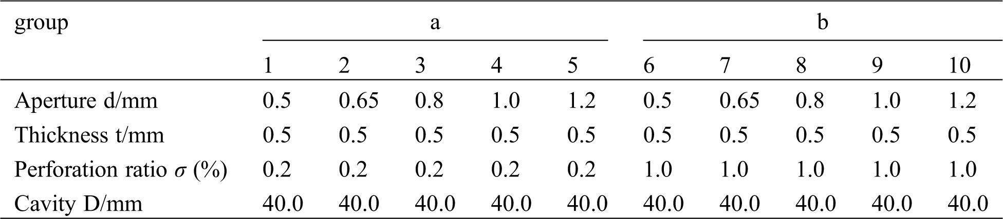
Though the overall trend of change of the sound absorption coefficient of the PCMPP with different perforation ratios was consistent, the variation range was small. Comparing the two groups of curves with different perforation rates, as the aperture increases from 0.5 to 1.2 mm, the absorption peak gradually decreases, and the sound absorption bandwidth presents a narrower trend. Specifically, for perforation ratio 0.2% group, sound absorption peak value decreased from around 0.99 at 550 Hz to 0.9 at 640 Hz. In the perforation ratio group of 1.0%, sound absorption peak value decreased from around 1.0 at 650 Hz to 0.72 at 750 Hz. In general, the results of the two groups of five experimental samples were all less than 10% in difference, and there was no phenomenon proving that the small aperture was inferior to the large aperture in the low perforation ratio. It is preliminarily speculated that the coupling effect of plastocene makes the small aperture of the perforated plate have a good performance in the low perforation ratio.
To confirm the speculation, conventional aluminium base MPPs were prepared by traditional machining methods. The preparation scheme is shown in Tab. 6, and the measurement results are shown in Fig. 12.
Table 6: Structural parameters of MPP with three kinds of perforation ratio
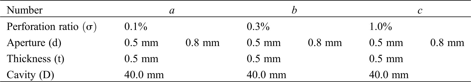
As shown in Figs. 12a and 12b, the overall variation rule of pore diameter on the sound absorption coefficient of conventional MPP was consistent. The sample with an aperture of 0.8 mm had better sound absorption effect than that of 0.5 mm at the perforation ratio of 0.1%. However, at the perforation ratio of 1.0%, the MPP with aperture of 0.5 mm had better sound absorption performance than that of 0.8 mm, having higher sound absorption coefficient and larger sound absorption band, which conforms to the theory of MPP proposed by Maa Dayou. By comparing the sound absorption coefficient of the PCMPP (Fig. 11) with that of the conventional MPP (Fig. 12), it is found that the sound absorption performance of the MPP with small aperture has been improved under lower perforation ratio.
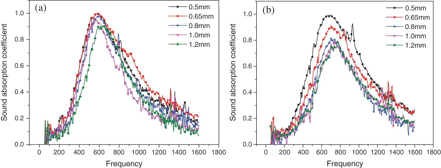
Figure 11: Effect of aperture on acoustics absorption coefficient of PCMPP
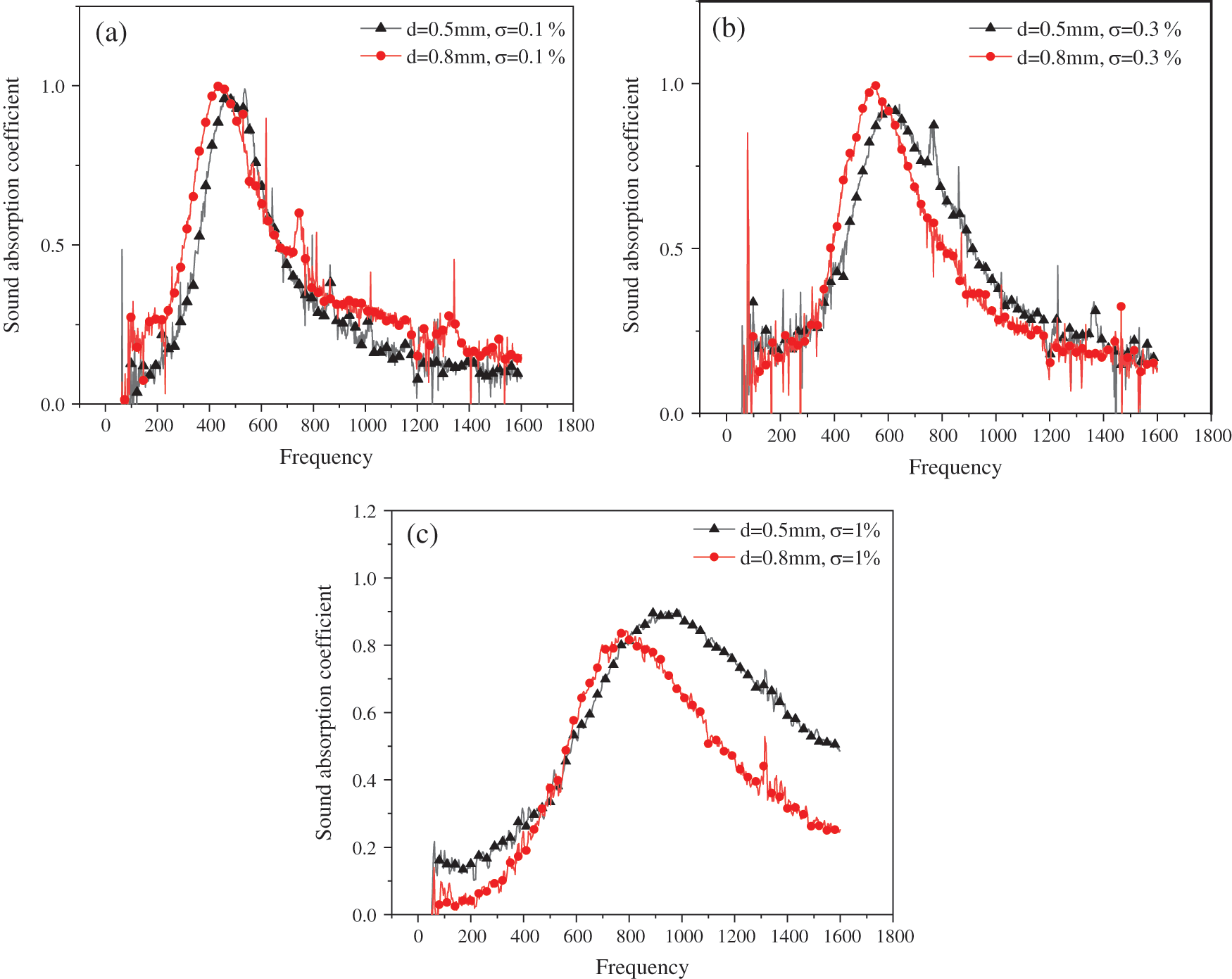
Figure 12: Experimental results of MPP with three kinds of perforation ratio
When the aperture increases, the sound mass of a single Helmholtz resonator increases, the hole spacing increases, and the sound capacity also increases. With the same perforation ratio, when the aperture increases, the number of holes per unit area decreases and the total perimeter of the PCMPPs’ hole is reduced. Therefore, the total friction area becomes smaller, and the sound energy of friction attenuation becomes smaller, so the absorption peak value of PCMPP decreases with the increase of aperture.
5.3 Effect of Cavity Behind Plate on Absorption Coefficient
The plastocene was embedded into a MPP with an aperture of 0.5 mm, plate thickness of 0.5 mm, and a perforated ratio of 0.2%. The effect of different cavity depths (20, 40, 60 mm) on the sound absorption performance of PCMPP was experimentally tested, and the results are shown in Fig. 13.
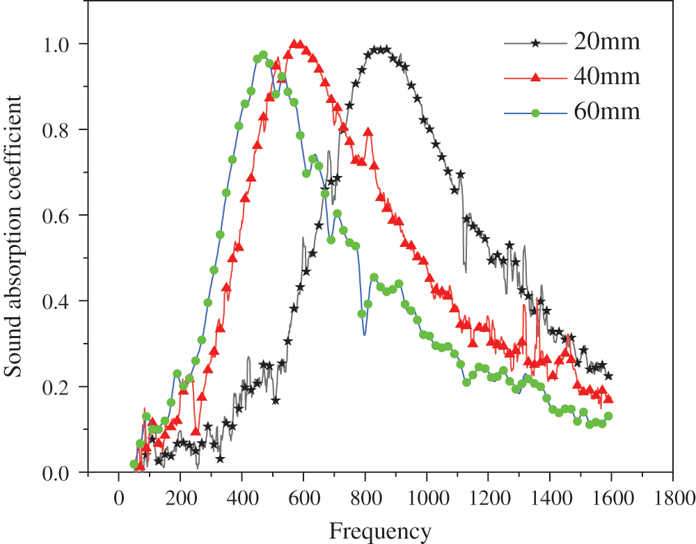
Figure 13: Effect of cavity behind plate on the sound absorption coefficient of PCMPP
As shown in Fig. 13, in general, the effect of the cavity behind the PCMPP on its sound absorption coefficient was consistent with the theory of Maa’s MPP. As the cavity spacing increased, the sound absorption peak moved to low frequency, and the absorption peak value was almost unchanged. When the cavity depth increases, the volume and acoustic capacitance of a single Helmholtz resonator increases. The resonant frequency and acoustic capacitance are inversely proportional, so the resonant frequency of the perforated plate decreases as the cavity depth increases. When the frequency of incident wave is the same as that of system, the sound absorption coefficient of PCMPP reaches the peak value. The resonant frequency decreases with the increase of cavity depth, that is, the frequency corresponding to the sound absorption peak of PCMPP decreases continuously.
5.4 Sound Absorption Mechanism of PCMPP
In Maa’s theoretical model of MPP, there is no thorough study on the material of MPP. However, a large number of experimental data show that the properties of the material itself will also affect the sound absorption performance of MPP in various aspects [17,33–34].
(1) The intervention of plastocene has an effect on the performance of MPP, while the plastocene itself has no sound absorption ability. Under the same volume, the mass of the plastocene is greater than 7075 aluminium alloy, and the plastocene is attached to the aluminium alloy MPP. It is speculated that the increase of its mass and the intervention of the new interfacial tension lead to the lower resonance frequency of the PCMPP compared with the traditional MPP, which makes the sound absorption peak move to the lower frequency band.
(2) From the vibration control equation of flexible MPPs, it can be seen that the stiffness, density and vibration mode of MPPs are changed due to the addition of plastocene. As a result, the displacement, average speed and average impedance changes of the entire plate change during the vibration process compared with MPP. Some scholars have studied the effect of vibration mode and damping on the flexible MPP. The research shows that the sound absorption capacity of the flexible MPP can be further increased with the increase of modal damping [24,35].
(3) Li et al. [20–22]. studied the addition of wool and metal fibers to perforated plates and found that with the addition of fiber materials, the resonant sound absorption frequency moved to low frequency and the sound absorption band widened. The author analyses that the reason for this phenomenon is that, due to the addition of fiber material, sound wave causes the fiber material to vibrate when it is incident on the perforated plate surface. After the sound wave enters the micropore, it causes the relative motion of fiber material to the medium, and consumes part of the sound energy through friction. As mentioned in this paper, filling some microholes of MPP with plastocene shows similar influence on sound absorption performance to a certain extent as adding fiber material to the microholes. Therefore, we speculate that the addition of plastocene may also have a similar sound energy loss mechanism.
The PCMPP is proposed for enhancing the acoustic performance of MPP. By testing the sound absorption coefficient of PCMPP and traditional MPP under the same parameters, the following conclusions can be drawn:
(1) In this paper, the sound absorption coefficients of PCMPP and conventional MPP with various structural parameters are compared by experiment. It is found that the peak value of sound absorption coefficient of PCMPP decreased by 150 Hz as compared to MPP when the aperture is 0.8 mm. In a certain range, PCMPP with larger aperture shows a greater effect on sound absorption property in low frequency domain. Moreover, the higher the perforation ratio, the greater the sound absorption bandwidth. In case of the aperture of 0.2 mm, the sound-absorbing performance of the PCMPP is further reduced, and the sound-absorbing performance of the PCMPP can be increased by increasing the perforation ratio.
(2) The effect of aperture (d), perforation ratio ( ) and back cavity (D) on the PCMPP are studied. It is found that the effect trend of sound absorption performance is consistent with the conventional MPPs studied by Maa Dayou. We also found that PCMPP makes the small aperture of the MPP have a good performance in the low perforation ratio.
(3) The plastocene has an obvious tendency to melt at 63°C, the PCMPP is not suitable for high-temperature environment since an increase in temperature will cause plastocene to soften and thus its adhesion will become weak gradually. Therefore, the proposed PCMPP has a great potential for applications with a proper temperature environment.
Acknowledgement: All support is greatly acknowledged and appreciated, especially the constructive discussion and criticism from colleagues.
Funding Statement: Thanks are due to projects supported by the National Natural Science Foundation of China (Grant Nos. 51705033 and U19A200125), the Education Department of Jilin Province (Grant No. JJKH20190560KJ), the Science and Technology Department of Jilin province (Grant Nos. 20190103001JH, 20180101324) provide financial support for this article.
Conflicts of Interest: The authors declare that they have no conflicts of interest to report regarding the present study.
1. Maa, D. Y. (1997). General theory and design of micro-perforated plate absorbers. Chinese Journal of Acoustics, 5, 385–393. [Google Scholar]
2. Maa, D. Y. (1975). Theory and design of sound absorption structure of micro-perforated plate. Science China, 18(1), 40–52. [Google Scholar]
3. Maa, D. Y. (1988). Design of microperforated plate constructions. Chinese Journal of Acoustics, 3, 174–180. [Google Scholar]
4. Lu, F. H., Ji, X. R., Wang, Z. M. (2006). Analysis and application of sound reflecting and absorbing characteristics of microperforated panel structures in lecture theatre. Chinese Journal of Acoustics, 31(3), 222–227. [Google Scholar]
5. Yu, W. Z. (2008). Design and noise reduction of elevated road barrier of microperforated plates with liner-change cavity. Environmental Pollution & Control (China), 30(7), 55–57. [Google Scholar]
6. Mosa, A. I., Putra, A., Ramlan, R., Esraa, A. A. (2020). Absorption coefficient of a double-layer inhomogeneous micro-perforated panel backed with multiple cavity depths. Acoustics Australia, 48(5), 1–10. DOI 10.1007/s40857-020-00176-4. [Google Scholar] [CrossRef]
7. Pedro, C., Carlos, D. L. C., Elena, R. M., Marcos, C., Francisco, S. (2019). A wideband triple-layer microperforated panel soundabsorber. Composite Strucurest, 226, 111–226. [Google Scholar]
8. Bucciarelli, F., Malfense, F. G. P., Meo, M. (2019). A multilayer microperforated panel prototype for broadband sound absorption at low frequencies. Applied Acoustics, 146, 134–144. DOI 10.1016/j.apacoust.2018.11.014. [Google Scholar] [CrossRef]
9. Wang, C., Huang, L., Zhang, Y. (2014). Oblique incidence sound absorption of parallel arrangement of multiple micro-perforated panel absorbers in a periodic pattern. Journal of Sound and Vibration, 333(25), 6828–6842. DOI 10.1016/j.jsv.2014.08.009. [Google Scholar] [CrossRef]
10. Wang, C., Liu, X. (2020). Investigation of the acoustic properties of corrugated micro-perforated panel backed by a rigid wall. Mechanical Systems and Signal Processing, 140, 106699. [Google Scholar]
11. Wang, C., Cheng, L., Pan, J., Yu, G. (2010). Sound absorption of a micro-perforated panel backed by an irregular-shaped cavity. Journal of the Acoustical Society of America, 127(1), 238–246. DOI 10.1121/1.3257590. [Google Scholar] [CrossRef]
12. Toyoda, M., Takahashi, D. (2008). Sound transmission through a microperforated-panel structure with subdivided air cavities. Journal of the Acoustical Society of America, 124(6), 3594–3603. DOI 10.1121/1.3001711. [Google Scholar] [CrossRef]
13. Motoki, Y., Kimihiro, S., Masayuki, M. (2005). Acoustical properties of microperforated panel absorbers with various configurations of the back cavity. Proceeding of ICSV 12, pp. 1–3. Lisbon. [Google Scholar]
14. Shen, X., Bai, P., Yang, X., Zhang, X., To, S. (2019). Low frequency sound absorption by optimal combination structure of porous metal and microperforated panel. Applied Sciences, 9(7), 1507. [Google Scholar]
15. Zhao, X. D., Yu, Y. J., Wu, Y. J. (2016). Improving low-frequency sound absorption of micro-perforated panel absorbers by using mechanical impedance plate combined with Helmholtz resonators. Applied Acoustics, 114, 92–98. DOI 10.1016/j.apacoust.2016.07.013. [Google Scholar] [CrossRef]
16. Zhao, X., Fan, X. (2015). Enhancing low frequency sound absorption of micro-perforated panel absorbers by using mechanical impedance plates. Applied Acoustics, 88, 123–128. DOI 10.1016/j.apacoust.2014.08.015. [Google Scholar] [CrossRef]
17. Li, G., Tang, X., Zhang, X., Qian, Y. J., Kong, D. Y. (2017). Investigation on the acoustic absorption of flexible micro-perforated panel with ultra-micro perforations. Materials Science and Engineering, 269, 012023. [Google Scholar]
18. Zhang, L. (2005). Study on sound absorption characteristics of resonant structure of inserted hose. China: Northwestern Polytechnical University. [Google Scholar]
19. Yang, C., Xu, H. M. (2020). Effects of the backing cavity on the acoustic absorption of a microperforated panel absorber. Applied Acoustics, 166, 107364. [Google Scholar]
20. Li, C. X., Hu, Y., He, L. Y. (2019). Simulation for the sound absorption of micro perforated panels with metal fibers using finite element method. Applied Acoustics (China), 38(6), 954–960. [Google Scholar]
21. Li, C. X., Xu, Y., Li, D. W. (2011). Effect of wool on widening sound absorption spectrum of thin microperforated panel. Journal of Northwestern Polytechnical University (China), 29(2), 263–267. [Google Scholar]
22. Xu, Y., Ren, Y. F., Li, C. X. (2011). Study on absorption performance of thin micro-perforated panel penetrated with copper fiber penetrated with copper fiber. Noise and Vibration Control, 31(3), 136–140. [Google Scholar]
23. Zhang, X. X., Wang, H. Q., Kong, D. Y., Qian, Y. J., Li, G. X. (2017). Acoustics property measurement and analysis of flexible micro-perforated panel absorber. Piezoelectrics & Acoustooptic (China), 39(5), 678–681. [Google Scholar]
24. Ren, S. W., Van Belle, L., Claeys, C., Xin, F. X. Lu, T. J. et al. (2019). Improvement of the sound absorption of flexible micro-perforated panels by local resonances. Mechanical Systems and Signal Processing, 117, 138–156. DOI 10.1016/j.ymssp.2018.07.046. [Google Scholar] [CrossRef]
25. Lee, Y. Y., Lee, E. W. M., Ng, C. F. (2005). Sound absorption of a finite flexible micro-perforated panel backed by an air cavity. Journal of Sound and Vibration, 287(1–2), 227–243. DOI 10.1016/j.jsv.2004.11.024. [Google Scholar] [CrossRef]
26. Zheng, W., Huang, Q., Li, S., Guo, Z. (2011). Sound absorption of hybrid passive-active system using finite flexible micro-perforated panels. Journal of Low Frequency Noise, Vibration and Active Control, 30(4), 313–328. DOI 10.1260/0263-0923.30.4.313. [Google Scholar] [CrossRef]
27. Zhu, Y. J., Zhang, Y., Xiong, W. B. (2012). Study on measurement system of sound absorption coefficient of impedance tube based on transfer function method. Acoust and Electronics Engineering, 4, 27–31. [Google Scholar]
28. ISO 10534-2. (1998). Acoustics-determination of sound absorption coefficient and impedance in impedances tubes—Part 2: Transfer-function method. Switzerland: International Organization for Standardization. [Google Scholar]
29. Chung, J. Y., Blaser, D. A. (1980). Transfer function method of measuring in‐duct acoustic properties. II. Experiment. Journal of the Acoustical Society of America, 68(3), 914–921. DOI 10.1121/1.384779. [Google Scholar] [CrossRef]
30. Koruk, H. (2014). An assessment of the performance of impedance tube method. Noise Control Engineering Journal, 62(4), 264–274. DOI 10.3397/1/376226. [Google Scholar] [CrossRef]
31. Krüger, J., Quickert, M. (1997). Determination of acoustic absorber parameters in impedance tubes. Applied Acoustics, 50(1), 79–89. DOI 10.1016/S0003-682X(96)00017-5. [Google Scholar] [CrossRef]
32. Hu, P., Mao, G. P., Zhao, X. D. (2013). Effect of structure parameter on sound absorption of micro-perforated panel absorber. Piezoelectric & Acoustooptics (China), 35(5), 624–627. [Google Scholar]
33. Sun, W. J., Su, Q. P., Kong, D. Y., Duan, X. H., Zhao, C. et al. (2013). Calculation of acoustical characteristics of micro-perforated panel considering the effect of panel. Journal of Vibration and Shock, 32(9), 150–154+172. [Google Scholar]
34. Chin, D. D. V. S., Bin, Y. M. N., Din, N. B. C., Musli, N., Din, N. B. C. (2018). Acoustic properties of biodegradable composite micro-perforated panel (BC-MPP) made from kenaf fibre and polylactic acid (PLA). Applied Acoustics, 138(September), 179–187. DOI 10.1016/j.apacoust.2018.04.009. [Google Scholar] [CrossRef]
35. Tournadre, J., Temiz, M. A., MartínezLera, P., De Roeck, W., Desmet, W. et al. (2016). Vibro-acoustic response of flexible micro-perforated plates: Impact of the boundary condition at the perforation walls. Proceedings of the 27th Conference on Noise and Vibration Engineering (ISMA2016Leuven, Belgium, pp. 407–422. [Google Scholar]
 | This work is licensed under a Creative Commons Attribution 4.0 International License, which permits unrestricted use, distribution, and reproduction in any medium, provided the original work is properly cited. |