DOI:10.32604/jrm.2021.013319
| Journal of Renewable Materials DOI:10.32604/jrm.2021.013319 | |
| Article |
Optimal Bioprinting Parameters and Experimental Investigation of Acellular Dermal Matrix Scaffold
1Rapid Manufacturing Engineering Center, School of Mechatronic Engineering and Automation, Shanghai University, Shanghai, China
2Shanghai Key Laboratory of Intelligent Manufacturing and Robotics, Shanghai University, Shanghai, China
3National Demonstration Center for Experimental Engineering Training Education, Shanghai University, Shanghai, China
4Shanghai Ninth People’s Hospital, Shanghai JiaoTong University School of Medicine, Shanghai, 200011, China
*Corresponding Authors: Haiguang Zhang. Email: haiguang_zhang@i.shu.edu.cn; Yan Gu. Email: yangu@shsmu.edu.cn
Received: 02 August 2020; Accepted: 30 September 2020
Abstract: Acellular dermal matrix (ADM) as a biomaterial is currently believed to be promising tissue repair improvement. With the development of tissue engineering, ADM is increasingly used as biological scaffolds. We explored the feasibility and performance of ADM biological scaffolds that fabricated by 3D printing. This paper presented our study on the printability of 3D printed ADM scaffolds, with a focus on identifying the influence of printing parameters/conditions on printability. To characterize the printability, we examined the fiber morphology, pore size, strand diameter, and mechanical property of the printed scaffolds. Our results revealed that the printability could be affected by a number of factors and among them, the most considerable one was related to the nozzle diameter and the composition of ADM. We then evaluated the biocompatibility in terms of cytotoxicity, cell proliferation and vivisection. In vitro evaluation of the ADM scaffolds was carried out and the experimental results indicated that cells were viable and proliferative during the period of study. In vivo results also indicated that the defect area was well repaired without any noticeable infection, hematoma and other conditions. In conclusion, ADM could be reconstructed with 3D printing technology and ADM biological scaffold has potential applications for tissue engineering.
Keywords: Bioprinting; acellular dermal matrix; scaffolds; printability; tissue engineering
Tissue engineering, as a novel technology with a final goal of planting artificial tissues or even organs to replace the natural extracellular matrix (ECM) until host cells can repopulate and reconstruct tissues inside the human body [1]. Along with the development of tissue engineering, the method of tissue repair is not limited to autologous tissue transplantation. Seed cells, cytokines and materials of tissue engineering scaffold are becoming the three essential elements of tissue engineering [2] Materials suitable for tissue engineering should be of good biocompatibility and biomechanical strength [3–7]. The quality of tissue engineering material is directly associated with the quality and the effect of tissue engineering scaffold in vivo.
Biological materials, with good performance in biocompatibility and anti-infective properties, are widely used in tissue reconstruction. Unlike synthetic polymer materials, biological materials are commonly used in contaminated wounds for the excellent biocompatibility. In addition to this, biological materials can provide a good adsorption interface for cell adhesion and tissue regeneration. As a collagen-like extracellular matrix material [8], Acellular dermal matrix (ADM) in different forms have been widely used in burns, plastic surgery, trauma repair, and so on [9–11]. Although ADM materials have good biocompatibility, mechanical properties, the characteristics of inducing cell proliferation, there are still some problems to be solved: (1) The surface structure of whole piece of ADM is relatively compact, which is difficult for cells to grow into the scaffold; (2) The pore diameter, porosity, connectivity and mechanical strength of three-dimensional structure cannot be precisely regulated as required; (3) Rapid degradation of non-crosslinked biomaterial scaffolds may lead to recurrence of defect. As one of the most effective methods to improve the mechanical stability, durability and rapid degradation of tissue engineered biological scaffolds, cross-linking has been widely used for a long time. Genipin (GP) has been widely used in the biological and medical fields such as tissue engineering cornea [12], bone and joint [13], tendon and soft tissue [14].
In recent years, the research on the manufacturing method of tissue engineering scaffold has achieved great success, a wide range of biomaterial scaffolds, such as skin, bone, cartilage, and nerve have been made for clinical use [15,16]. An ideal tissue engineering scaffold must have overall constructions, internal structures, mechanical properties and material properties [17,18]. Currently, 3D bioprinting based on the layered deposition of fibers is extensively studied and widely used in clinic. Notably, the application of 3D printing can reduce the waste of materials to a large extent and fabricate tissue engineering scaffolds with suitable overall constructions and internal structures according to the different structures of the in vivo defects [19–21]. Also, 3D bioprinting scaffold can control of pore and fiber diameter to meet the requirements of cell adhesion, proliferation, differentiation, and extracellular matrix formation [22].
This paper attempts to combine the advantages of the 3D bioprinting technology and ADM biological materials to produce scaffold similar to the host tissue. The 3D bioprinting technology can make the scaffold with high reproducible construct, by which the viable ADM scaffold with predefined porosity and connectivity can be produced easily [23–25]. Moreover, interconnected construct of the printed scaffold can be easily customized and tailored, which is very important for large or severe tissue defects. In this work, we analyzed and optimized printing parameters in detail for bioprinting scaffold, such as concentration of solution, nozzle diameter, extrusion and printing speed that produce fibers of scaffold with suitable size and high uniformity through the orthogonal test. The most important parameters that affect bioprinting scaffold forming effect and the interaction between the parameters will be identified. With the optimize parameters, we fabricated the ADM scaffold by 3D bioprinting and added GP to keep the shape of the ADM scaffold. The mechanical properties, hydrophilic, and biocompatibility of the scaffolds were tested.
ADM freeze-dried powder (Jiangsu Unitrump Biomedical Technology CO., Ltd, China) was fully mixed with glacial acetic acid (Sinopharm Chemical Reagent Co., Ltd, China) to print exterior scaffolds. The PLA woven mesh (National key laboratory of fiber material modification, Donghua University) were used as interlayer. Genipin powder (GP, MedChem Express, Monmouth Junction, NJ, USA) was dissolved in pure alcohol to prepare a 0.625 wt% crosslinking agent.
A robot dispensing machine (Shanghai Pioneer Electronic Technology Co., Ltd., China) was used to print the scaffolds. A WDW-1 materials testing machine (Songdun Machine Equipment Co., Ltd., Shanghai, China) was used to test the mechanical property of scaffolds. A contact angle goniometer (Chengde test machine factory, China) was used to test the hydrophilic and the contact angle of scaffolds. A 5% CO2 incubator (Thermo Fisher Scientific Inc., USA) was used to culture cell and tissue in vitro by simulating a growth environment, which stays in a stable temperature of 37°C, constant pH value (pH value: 7.2–7.4), higher relative saturated humidity (95%). A scanning electron microscope (SEM, Hitachi, Ltd., Japan) was used to assess the morphology of fibers and cells on ADM scaffolds.
2.2 Preparation of Composite Scaffolds
ADM powder was fully mixed with glacial acetic acid (Fig. 1A) and the mixed solution was printed with a robot dispensing machine at different concentration of solution, nozzle diameter, extrusion and printing speed, as shown in Fig. 1C. Tab. 1 shows the printing parameters used in this experiment. Then, the ADM scaffold was moved from the receiving platform and placed in a container with prepared cross-linking agent.
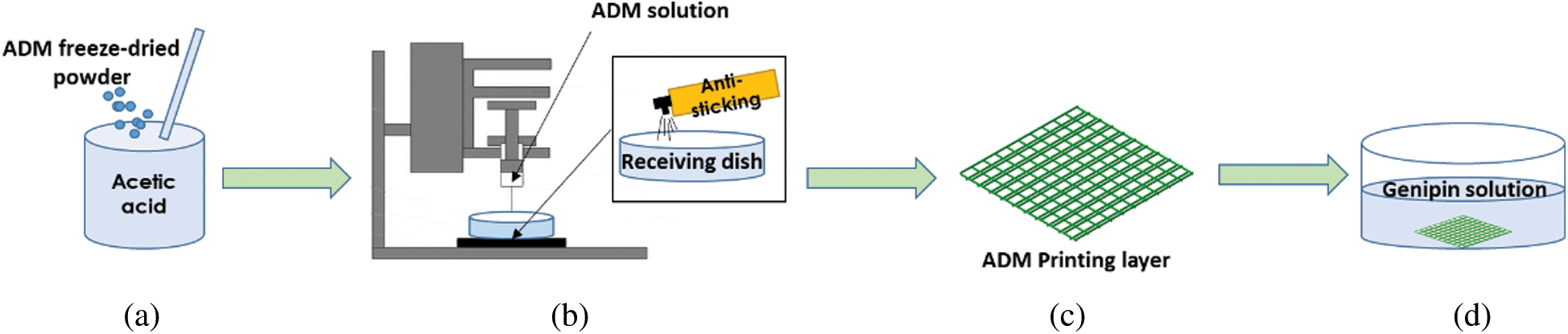
Figure 1: Schematic diagrams of the fabricating the multi-layer ADM-PLA composite scaffolds
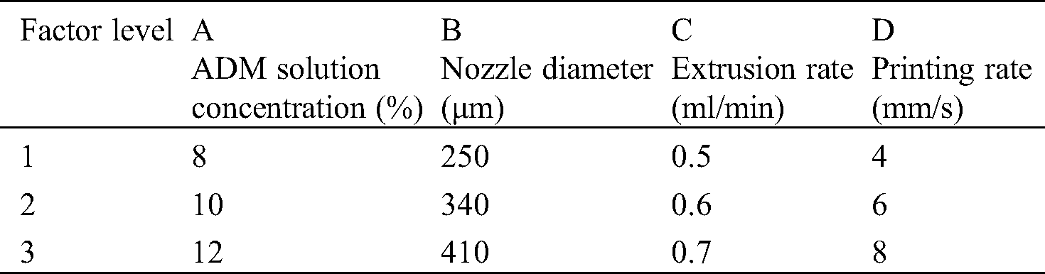
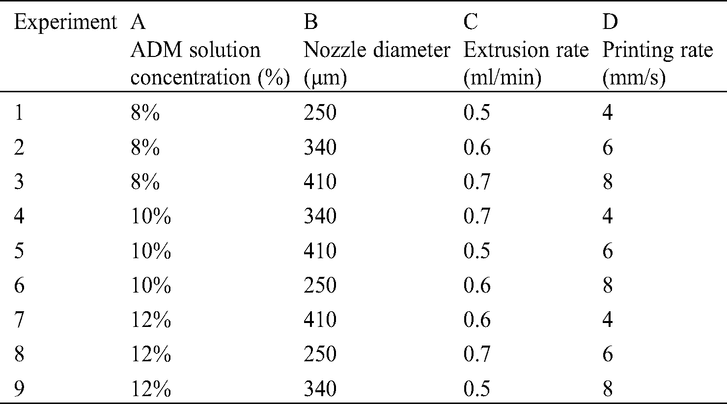
Orthogonal test [26,27] is a technique that provides an efficient method for design optimization. The experimental design allows the study of interaction between different parameters. The orthogonal array combines different parameter combinations and their levels for each experiment. In the test, the parameters of the printing process were set as factors with different levels. The scaffold molding state and the fiber diameter uniformity were set as indicators. Based on the above experiments, 3 levels were set for each factor, as shown in Tab. 1. Orthogonal table L9 (34) was selected to arrange the test, and the corresponding levels of each factor were filled in table L9 (34), as shown in Tab. 2. The occurrence times of different levels in each column were the same, and each horizontal combination formed horizontally in any column only appeared once.
In the study of tissue engineering, due to the interlayer interface effect, the biological scaffold cannot provide enough mechanical strength for tissue repair to maintain the contour and volume of the scaffold. As one of the most effective methods to improve the mechanical stability, durability and rapid degradation of tissue engineered biological scaffolds, cross-linking has been widely used for a long time. As a natural extracted cross-linking agent, GP was dissolved in pure alcohol at a concentration of 0.625% (wt). The fabricated scaffolds were kept at room temperature for 20 min and then at 4°C for 12 h for complete crosslinking (Fig. 1D).
After the fabrication with optimized parameters from orthogonal test, samples were tested to explore the mechanical properties of ADM scaffolds. The size of samples was 30 mm × 10 mm. To obtain the suture strength, suture threads were used to simulate the actual suture in vivo at a short end 2 mm from the edge of samples and the fixture of materials testing machine. A constant speed of 0.5 mm/min was applied to each construct until fracture, and the space between the upper and lower clamps was 10 mm. Six samples were tested and the stress of each sample was recorded from the beginning of the test to the point of the complete fracture.
The degradation property of composite scaffolds were tested by monitoring the weight changes before and after being immersed in the RPMI 1640 culture medium(CM) (Thermo Fisher, USA) with 10% fetal bovine serum, 0.30 mg/mL L-glutamine, 4.766 mg/mL HEPES, 0.85 mg/mL NaHCO3, 1% penicillin (10 000 units/mL), and 10 000 μg/mL streptomycin, phosphate buffered saline (PBS) (GE Healthcare, USA) and artificial serum/plasma (ASP) (Huzhou InnoReagents biotechnology Co., Ltd., China). First, the ADM scaffolds were weighed. Then, the weighted samples were incubated in a carbon dioxide incubator at 37°C until the set time. Specimens were taken out at each degradation periods, and washed thoroughly with distilled water and then dried. Scaffolds of experiment group and control group were weighed after vacuum dried (n = 3 per group), and the weight of scaffolds were recorded.
Before cells attachment, HUVECs (Zhongqiaoxinzhou Biotech Co., Ltd., Shanghai, China) were routinely cultured and maintained in a 5% CO2 humidified incubator at 37°C in a standard Petri dish (Corning, NY) with RPMI 1640 culture medium. Besides, cells were passaged every 3 days, and the culture medium should be refreshed every day. Meanwhile, scaffolds were immersed in 75% ethanol for 12 h under UV radiation, and also washed with PBS for three times. Then, scaffolds were immersed in fresh RPMI 1640 culture medium for 6 h before injection. After trypsinization, cell suspension with a density of 5 × 10⁶ cells/mL was prepared with fresh medium and 10 mL of prepared suspensions were slowly injected into the dish to cover the whole scaffold. After 4 h of cell attachment, the cell-laden scaffolds were statically cultured.
To assess the cell viability of the attached HUVECs, a Live-Dead Cell Staining Kit (Biovision, Inc., San Francisco, CA) was used. Live cells and dead cells were stained by green fluorescent dye and red fluorescent dye propidium iodide (PI) respectively. With the help of an inverted fluorescent microscope (Eclipse Ti-U, Nikon Instruments Inc., Japan), the cellular morphology and Live-Dead fluorescence were observed.
The rat myogenic cells (L6) from the Chinese Academy of Sciences were routinely cultured in Dulbecco’s Modified Eagle’s Medium (DMEM, Thermo Fisher Scientific Inc., USA) containing 10% fetal bovine serum (FBS, Thermo Fisher Scientific Inc., USA) and shaken in an incubator for 24 h. The cells were maintained at 37°C in 5% CO2 incubator in a standard Petri dish, passaged every 3 days, with the media being refreshed every day. The ADM scaffolds were immersed in 75% ethanol for 12 h under UV radiation, then, washed three times with PBS to replace the ethanol from scaffolds. After that, the construct was immersed in fresh DMEM medium for 12 h before injection. After trypsinization, a cell suspension with a density of 5 × 10⁶ cells/mL was prepared in medium. Then, 10 mL of cell suspensions was slowly perfused into scaffolds. After 4 h of cell attachment, the cell-laden constructs were statically cultured, with the medium changed every day in a CO2 incubator. The CCK-8 assay (KeyGEN BioTECH Co., Ltd., Jiangsu, China) was used to measure the cytotoxicity of the ADM scaffolds and blank control group at different time points (1, 2, 3, and 4 days).
The ADM scaffolds were histologically examined to assess its suitability for cell profiling. The fibers were fixed in the 6-well plate, and 1 mL L6 cell suspension was added to each well at a density of 5 × 10⁶ cells/mL. After culturing for 3 and 5 days, the fiber was fixed in 4% paraformaldehyde for 24 h. To assess the morphology of cells on the fabricated scaffolds, the samples were observed by SEM.
Five male SD rats (200 g, Animal laboratory center of Shanghai Ninth People’s Hospital, Shanghai JiaoTong University School of Medicine) were inhaled with isoflurane, the abdominal wall was disinfected after anesthesia, and the abdominal wall muscle tissue defect measuring 25 mm × 25 mm was created in the middle of abdominal wall. Then ADM scaffolds were used for repair, and the skin was closed after repair. The rats were sacrificed at 4 weeks and the abdominal wall repair and abdominal adhesion were observed [28]. After HE (KeyGEN BioTECH Co., Ltd., China) staining, tissue regeneration was observed under normal microscope.
The Origin 2017 software was used for statistical analysis. In order to determine which populations were significantly different, all data are presented in form of mean ± standard deviation (SD) and analyzed with one-way analysis of variance. Data differences were statistically significant when values of p were lower than 0.05.
3.1 Observation of Fiber Forming Effect
The fibers’ morphology of 9 experiment groups are shown in Fig. 2, which can directly and roughly express the forming effect of different groups of fibers. From Figs. 2A–2C, we can see the fiber forming morphology of experiment 1–3 and the fiber forming is discontinuous and uneven. Among them, the samples in Fig. 2A (experiment 1) basically could not form continuous fiber, the samples in Fig. 2B (experiment 2) partly formed continuous fiber with uneven diameter of single fiber and samples of experiment 3 basically formed continuous fiber, but the material caking phenomenon did not improve significantly. The fibers of experiment 4–6 were formed continuously and their diameters were relatively uniform (Figs. 2D–2F). Among them, the fibers in Fig. 2D (experimrnt 4) were thin and deformed, while the fibers in Fig. 2F (experiment 6) were thick and the visible pores were significantly reduced. The fibers in Figs. 2G–2I (experiment 7–9) were formed continuously, but the low material concentration resulted in obvious structural collapse. Among them, the samples in Fig. 2G (experiment 7) showed very little pore structure and were superior to those in Figs. 2H (experiment 8) and 2I (experiment 9).
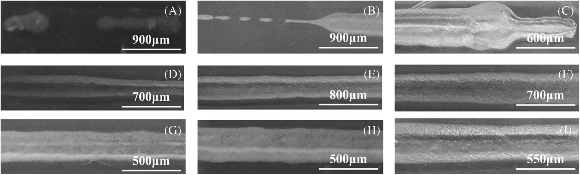
Figure 2: Morphology of fibers in different factors. (A) Experiment 1, ADM solution concentration is 8%, nozzle diameter is 250 μm, extrusion rate is 0.5 ml/min, printing rate is 4 mm/s. (B) Experiment 2, ADM solution concentration is 8%, nozzle diameter is 340 μm, extrusion rate is 0.6 ml/min, printing rate is 6 mm/s. (C) Experiment 3, ADM solution concentration is 8%, nozzle diameter is 410 μm, extrusion rate is 0.7 ml/min, printing rate is 8 mm/s. (D) Experiment 4, ADM solution concentration is 10%, nozzle diameter is 340 μm, extrusion rate is 0.7 ml/min, printing rate is 4 mm/s. (E) Experiment 5, ADM solution concentration is 10%, nozzle diameter is 410 μm, extrusion rate is 0.5 ml/min, printing rate is 6 mm/s. (F) Experiment 6, ADM solution concentration is 10%, nozzle diameter is 250 μm, extrusion rate is 0.6 ml/min, printing rate is 8 mm/s. (G) Experiment 7, ADM solution concentration is 12%, nozzle diameter is 410 μm ,extrusion rate is 0.6 ml/min, printing rate is 4 mm/s. (H) Experiment 8, ADM solution concentration is 12%, nozzle diameter is 250 μm, extrusion rate is 0.7 ml/min, printing rate is 6 mm/s. (I) Experiment 9, ADM solution concentration is 12%, nozzle diameter is 360 μm, extrusion rate is 0.5 ml/min, printing rate is 8 mm/s
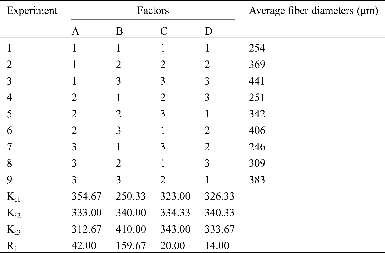
3.2 Measurement of Fiber Average Diameter
Through the observation of fiber morphology, we can observe the forming effect of different parameter combination. However, this does not mean that we can get the optimal parameter combination, nor can we directly get the influence degree of each parameter on the fiber forming quality. Therefore, this experiment will be quantified by measuring and calculating the average diameter of fiber. Results of the effect of the four factors on the average diameters of ADM fibers is presented in Tab. 3, where Ki1 represents the average of the results of factor “i” if the level is 1. For instance, K11 is the average of the results of the first factor (ADM solution concentration) when the level is 1 ((254 + 369 + 441)/3 = 354.67). Ri represents the difference between the largest and the smallest Kij values of row “j”. For example, 42.00 is the difference between 354.67 and 312.67. A large value of Ri indicates that the effect of factor “i” on average fiber diameters is significant. Based on the Ri value in Tab. 3, 159.67 > 42.00 > 20.00 > 14.00, and the effect of the four factors on the average diameters of ADM fibers can consequently be listed in the following order: nozzle diameter > ADM solution concentration > extrusion rate > printing rate.
Table 3: Effects of the four factors on average fiber diameters
Thus, ADM powder was fully mixed with glacial acetic acid in the mass-volume ratio of 1:10. The mixed solution was extruded from a syringe with a 23-gauge needle at room temperature. The extrusion rate and the printing rate are 0.7 ml/min and 6 mm/s.
3.3 Morphology of Fabricated Scaffolds
After the fabrication with determined process parameters, the microstructure and morphology of the ADM scaffolds was shown in Fig. 3. The surface of the control group scaffold looked rough (Fig. 3B), which could benefit the cells to attach and proliferate. Based on the SEM pictures of the surface and inner part of the ADM scaffold, Origin software was used to quantitatively calculate the fiber diameter and pore size in the supporting materials (Figs. 3C and 3D). According to the results, the fiber diameter and pore diameter distribution of ADM scaffolds prepared by 3D printing process had the following characteristics. About 80% of fibers had diameters of 300 μm–360 μm, and 92% of the holes showed diameters of 300 μm–500 μm.
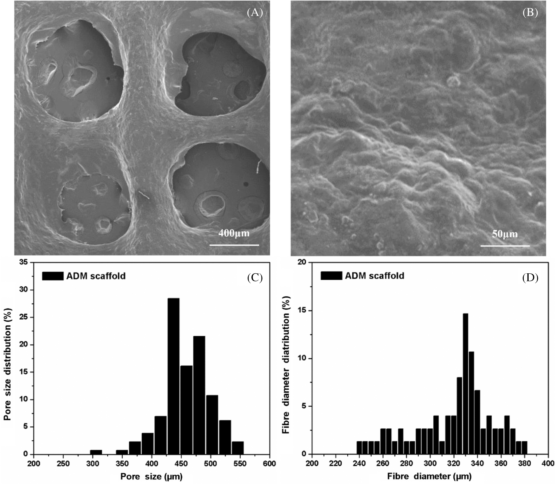
Figure 3: (A) Macro structure of the ADM scaffold made by 3DP. (B) Micro structure of the ADM scaffold made by 3DP. (C) Fiber diameter distribution of the ADM scaffold. (D) Pore size distribution of the ADM scaffold
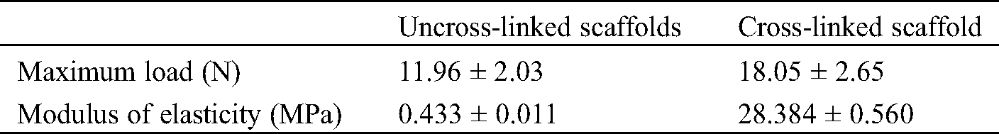
The suture and tensile properties of the engineered scaffolds are key parameters in clinical tissue regeneration. The results can be seen from Fig. 4. The average maximum load of ADM scaffolds was 18.05 N, which could meet the accepted clinical standards and higher than the scaffold without crosslinking process. Also, Modulus of Elasticity (MOE) of cross-linked ADM scaffolds was far above which of uncross-linked ADM scaffolds (Tab. 4).
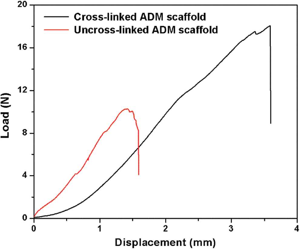
Figure 4: Load–displacement curves from the suture test of the scaffolds
Table 4: Mechanical properties of ADM scaffolds before and after crosslinking
The degradation rate of scaffolds increased basically the same during the culture process in PBS (Fig. 5A), ASP (Fig. 5B) and CM (Fig. 5C). As shown in figures, the degradation curves of ADM scaffolds in AP were relatively flat for first 14 days, while the subsequent degradation curves were relatively uniform in CM, PBS and AP.
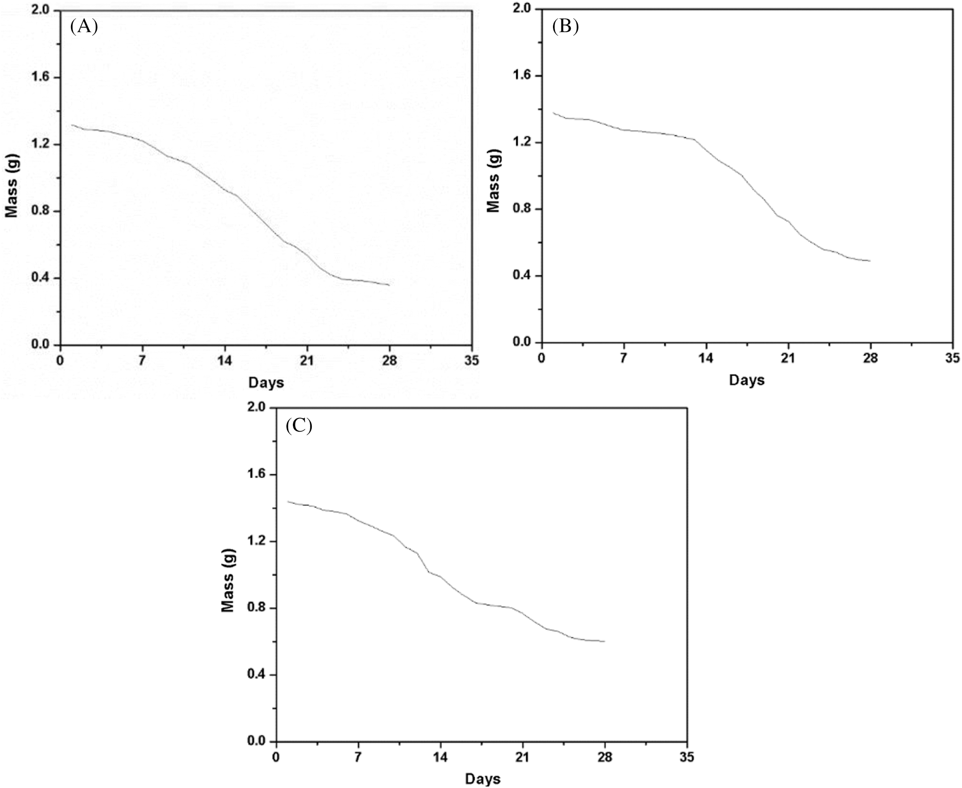
Figure 5: Degradation rate of ADM scaffolds. (A) The mass variation curves of ADM scaffolds in PBS. (B) The mass variation curves of ADM scaffolds in ASP. (C) The mass variation curves of ADM scaffolds in CM
3.6 Cell Viability of the Scaffold
To investigate the biocompatibility of the ADM scaffolds, HUVECs were seeded and statically cultured in scaffolds. Fig. 6A showed the microscopic morphology of cells attached to fiber surface after 4 h, which proof that seeded cells could attach to the surface of the scaffolds quickly. However, the cell distribution in this part was not uniform. Also, the absence of cells was mainly found in the center part of the scaffold, which was caused by the nonuniformity and flow of the cell suspension during the 4 h attachment period. After 2 days of culturing, the increasing of cells was observed from Fig. 6C, and the cells grew into the blank part. From Fig. 6E, HUVECs are distributed on the fiber uniformly after culturing for 3 days. Figs. 6B, 6D, and 6F showed the fluorescent images of die cells. These results indicate that cell distribution in the scaffold was not very uniform at the initial stage, cells maintained high viability and were distributed uniformly after culturing for 3 days. This suggests that the materials and the fabrication process were nontoxic for cells and the engineered 3D scaffold is favorable for cellular attachment, spreading and growth.
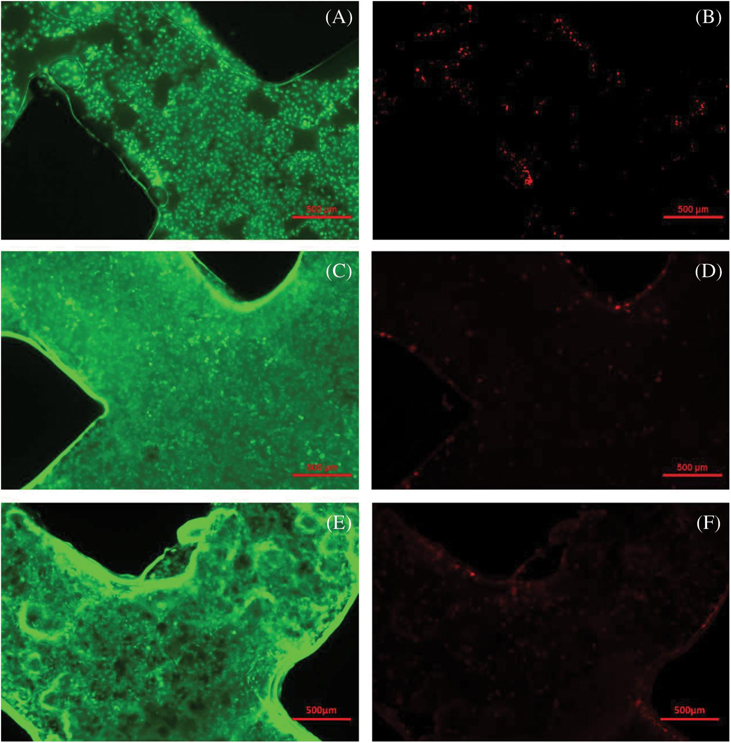
Figure 6: Live/Dead cell morphology and fluorescent images of the scaffolds. (A, B) Fluorescent images of cells after 4 h attachment. (C, D) Fluorescent images of cells cultured for 2 days. (E, F) Fluorescent images of cells cultured for 3 days
3.7 Cell Viability and Morphology
The SEM image showed that the L6 cells adhered on ADM scaffold rapidly and effectively (Figs. 7A–7C). The ADM scaffold was almost covered by cells after culturing for 24 h and cells completely covered the scaffold for 12 h more. Furthermore, the CCK-8 assay results revealed no significant differences (p > 0.05) among the ADM scaffolds and the blank control group on days 1, 2, 3, and 4 (Fig. 7D).
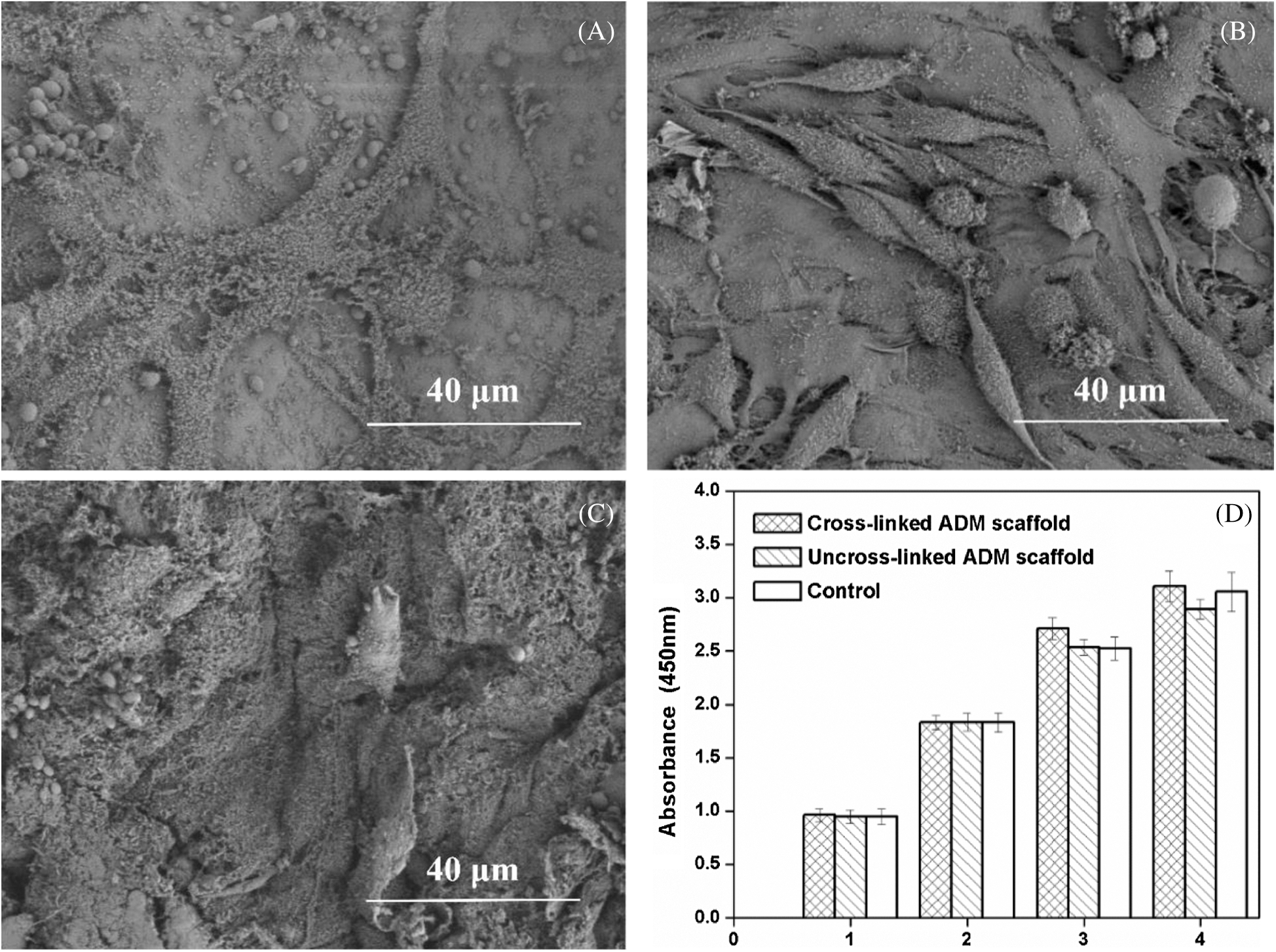
Figure 7: Cell viability of the ADM scaffold. (A) Cell adhesion at 24 h after culturing. (B) Cell adhesion at 48 h after culturing. (C) Cell adhesion at 72 h after culturing. (D) Cell viability of the cells on the ADM scaffolds at days 1,2,3,4
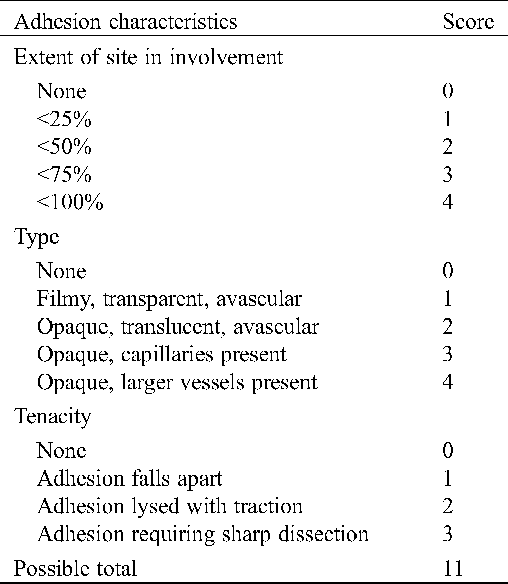
In the experiment, intestinal fistula recurrence and other complications did not found in all the rats at 4 weeks after implantation (Fig. 8). Fig. 8B showed the reparation in without scaffold and intestinal adhesions have appeared at defect area (Fig. 8B). At 4 weeks, the subcutaneous tissue in the defect area was well repaired, and infection, seroma, hematoma and other conditions weren’t observed in experiment group (Fig. 8C). According to the observation of the abdominal surface, the surface was well repaired with ADM scaffolds, covered with complete tissue at 8 weeks (Fig. 8D), and no obvious intestinal adhesion was observed and the average adhesion score was 2.2 ± 1.1 (Tab. 5). HE staining showed that at 4 weeks, most ADM scaffolds were degraded, and the black arrows showed that the peritoneal tissues were repaired, forming a relatively complete repair area (Fig. 9).
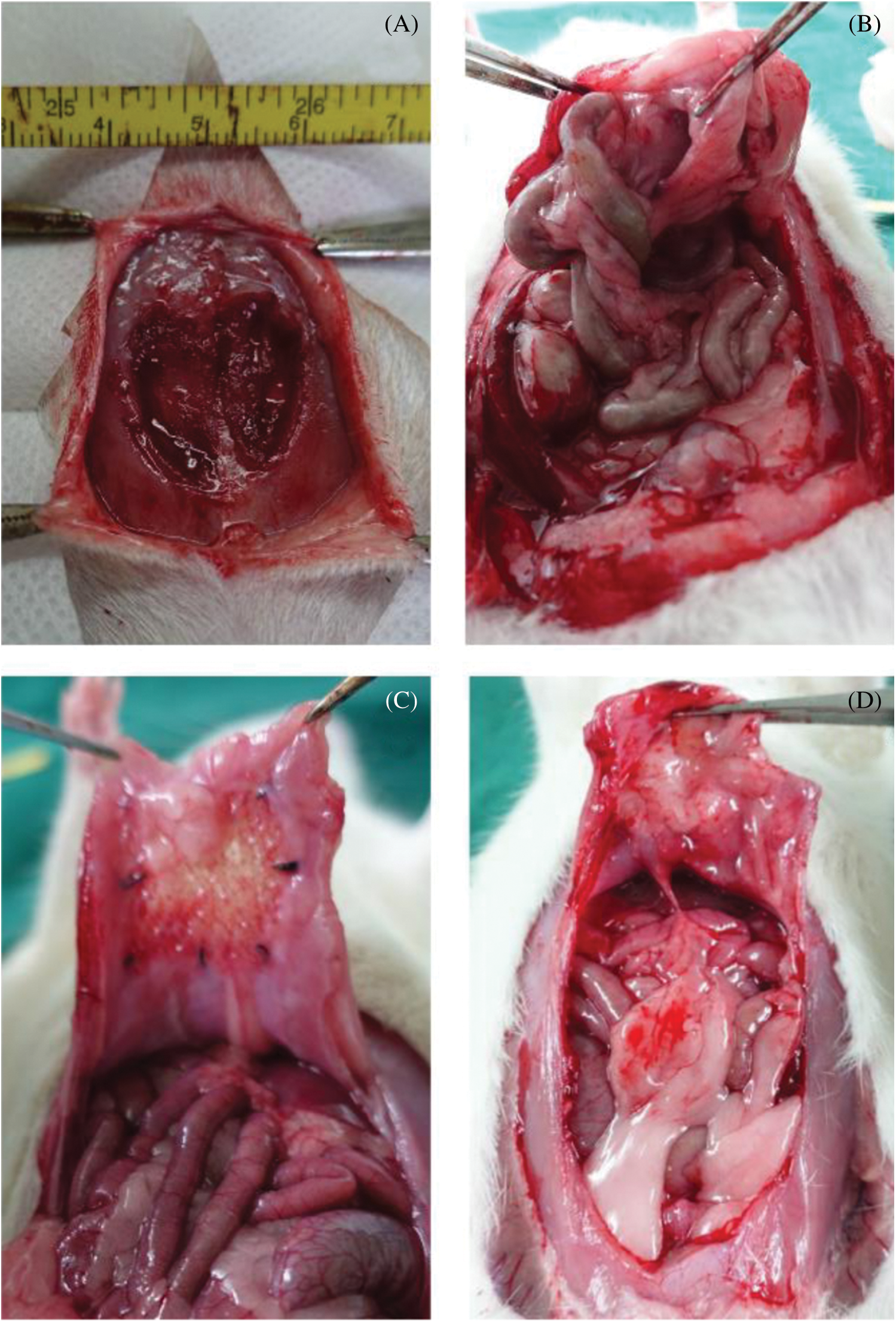
Figure 8: Morphology of implanted ADM scaffolds and surrounding tissue. (A) Defect creation before implantation. (B) The observation of blank group at 4 weeks. (C) The observation of experiment group at 4 weeks. (D) The observation of experiment group at 8 weeks
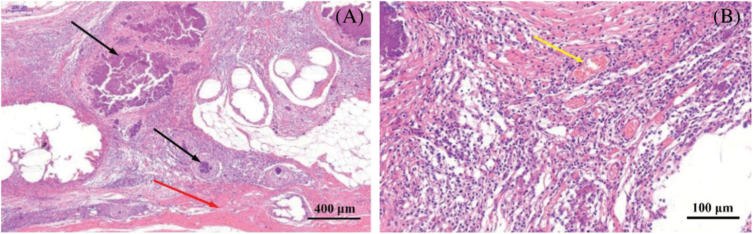
Figure 9: Histological evaluation of ADM scaffolds four weeks after implantation. (A) The black silk arrow points to the non-degraded AMD material, and the red arrow points to the tissue covering the scaffold surface. (B) The yellow arrow indicates that a large amount of neovascularization occurs around the ADM material
Table 5: Site-specific classification of adhesions
With the development of tissue engineering, many scaffolds from different materials are used to replace defective tissues. ADM, as a biomaterial derived from tissue, has been successfully applied to improve wound healing [29]. In addition, the scaffolds fabricated by using ADM showed high biological stability and the characteristics of small pore both in vitro and in vivo, which could support the proliferation and growth of cells [8]. In this study, the lyophilized ADM powder was dissolved and reconstructed with 3D printing technology to fabricate tissue engineering scaffold.
The fabrication process parameters could influence the formation and properties of the scaffolds. This paper introduces the orthogonal test design [30] to obtain the optimal process parameter combination of ADM scaffold. It is a balanced arrangement of groups and applied broadly in many fields to optimize test designs. In this study, nozzle diameter, ADM solution concentration, extrusion rate and printing rate were selected as targets for investigation. All other factors, such as ambient temperature and humidity were maintained. According to the analysis of average diameter of ADM fibers, the nozzle diameter has the greatest impact on fiber diameter size. Besides, the microscopy images of the fibers showed that the concentration of ADM solution effects the formation of ADM fibers a lot. Combining these process parameters, we can obtain 3D printing supports with pore size of about 300 μm-350 μm, which can stimulate cells to show better activity, achieve better growth and proliferation, which is suitable for tissue construction and repair.
However, current reconstructed ADM scaffolds still have some issues, such as weak mechanical strength. Mechanical properties play an important role in tissue engineering and tissue regeneration [31]. Through the experimental study, we found that the suture load value of the cross-linked scaffolds was 18.05 N (Fig. 4), which could basically meet the suture strength for tissue repair [31–33].
To confirm whether the cross-linked ADM scaffolds would degrade rapidly before the tissue regeneration and lead to failure of reparation and recurrence, Live/Dead staining were tested and rat myogenic cells were cultured on the fabricated scaffolds. Live/Dead staining results showed high viability of cells, which proves that the fabrication process and materials were nontoxicto cell growth. The SEM of cultured scaffolds give out the result that the cells could completely cover the scaffolds after culturing for 48 h, which indicated the scaffolds are suitable for early vascularization and beneficial to tissue repair. Besides, CCK-8 results showed that the process of 3D printing ADM scaffold did not produce cytotoxicity and Genpin cross-linking agent did not produce new cytotoxicity. We planted L6 cells on the composite scaffold. And the ADM composite scaffold was conducive to cell adhesion and proliferation, which was completely covered by cells in 36 h. The 3D printed ADM scaffold retains the advantages of ADM material for cell adhesion and proliferation.
Furthermore, ADM scaffolds were implanted in vivo to evaluate their practical application. A defect was created in the abdominal wall of SD rats and the ADM scaffolds was covered and replaced by regenerated muscle tissue in 4 weeks (Fig. 8). From Fig. 9, a large number of new blood vessels and fibrous tissues can be seen between the degraded ADM scaffolds, which further proves that ADM materials rich in collagen and extracellular matrix can promote cell proliferation, angiogenesis and tissue regeneration in the scaffolds.
In this study, we have successfully demonstrated the design and manufacturing of the ADM material to tissue engineering scaffolds. More experiments should be conducted to study the physical properties of the scaffolds and match the degradation rate of the ADM scaffolds. Moreover, the co-culture of multiple cells should be proceeded to explore the cell-cell and cell-matrix interaction and the potential tissue engineering applications.
Funding Statement: This research was funded by National Natural Science Foundation of China, Grant Nos. 51775324 and 81970455.
Conflicts of Interest: The authors declare that they have no conflicts of interest to report regarding the present study.
1. Mironov, V., Kasyanov, V., Drake, C., Markwald, R. R. (2008). Organ printing: Promises and challenges. Regeneration Medicine, 3(1), 93–103. DOI 10.2217/17460751.3.1.93. [Google Scholar] [CrossRef]
2. Yang, Q., Xu, H. W., Hurday, S., Xu, B. S. (2016). Construction strategy and progress of whole intervertebral disc tissue engineering. Orthopaedic Surgery, 8(1), 11–18. DOI 10.1111/os.12218. [Google Scholar] [CrossRef]
3. Mi, H. Y., Jing, X., Napiwocki, B. N., Hagerty, B. C., Chen, G. et al. (2017). Biocompatible, degradable thermoplastic polyurethane based on polycaprolactone-block–polytetrahydrofuran-block-Polycaprolactone copolymer for soft tissue engineering. Journal of Materials Chemistry B Materials for Biology & Medicine, 5(22), 4137–4151. [Google Scholar]
4. Wang, W., Deng, D., Wang, B., Zhou, G., Zhang, W. et al. (2017). Comparison of autologous, allogeneic, and cell-free scaffold approaches for engineered tendon repair in a rabbit model—A pilot study. Tissue Engineering Part A, 23(15), 750–761. DOI 10.1089/ten.tea.2016.0447.
5. Faulk, D. M., Londono, R., Wolf, M. T., Ranallo, C. A., Carruthers, C. et al. (2014). ECM hydrogel coating mitigates the chronic inflammatory response to polypropylene mesh. Biomaterials, 35(30), 8585–8595. DOI 10.1016/j.biomaterials.2014.06.057.
6. Ge, L., Cao, C., Chen, S., Shao, B., Li, Q. et al. (2017). Preparation of laminin/nidogen adsorbed urinary bladder decellularized materials via a mussel-inspired polydopamine coating for pelvic reconstruction. American Journal of Translational Research, 9(12), 5289–5298.
7. Wang, L., Yang, J., Ran, B., Yang, X., Zheng, W. et al. (2017). Small molecular TGF-β1-inhibitor-loaded electrospun fibrous scaffolds for preventing hypertrophic scars. ACS Applied Materials & Interfaces, 9(38), 32545–32553. DOI 10.1021/acsami.7b09796. [Google Scholar] [CrossRef]
8. Won, J. Y., Lee, M. H., Kim, M. J., Min, K. H., Ahn, G. et al. (2019). A potential dermal substitute using decellularized dermis extracellular matrix derived bio-ink. Artificial Cells, Nanomedicine, and Biotechnology, 47(1), 644–649. DOI 10.1080/21691401.2019.1575842. [Google Scholar] [CrossRef]
9. Cole, W., Samsell, B., Moore, M. A. (2018). Achilles tendon augmented repair using human acellular dermal matrix: A case series. Journal of Foot and Ankle Surgery, 57(6), 1225–1229. DOI 10.1053/j.jfas.2018.03.006. [Google Scholar] [CrossRef]
10. Hu, Y., Dan, W., Xiong, S., Kang, Y., Dhinakar, A. et al. (2017). Development of collagen/polydopamine complexed matrix as mechanically enhanced and highly biocompatible semi-natural tissue engineering scaffold. Acta Biomaterialia, 47, 135–148. DOI 10.1016/j.actbio.2016.10.017.
11. Getova, V. E., van Dongen, J. A.,Brouwer, L. A., Harmsen, M. C. (2019). Adipose tissue-derived ECM hydrogels and their use as 3D culture scaffold. Artificial Cells, Nanomedicine, and Biotechnology, 47(1), 1693–1701. DOI 10.1080/21691401.2019.1608215. [Google Scholar] [CrossRef]
12. Grolik, M., Szczubiatka, K., Wowra, B. (2012). Hydrogel membranes based on genipin-cross-linked chitosan blends for corneal epithelium tissue engineering. Journal of Materials Science: Materials in Medicine, 23(8), 1991–2000. DOI 10.1007/s10856-012-4666-7. [Google Scholar] [CrossRef]
13. Frohbergh, M. E., Katsman, A., Botta, G. P. (2012). Electrospun hydroxyapatite-containing chitosan nanofibers crosslinked with genipin for bone tissue engineering. Biomaterials, 33(36), 9167–9178. DOI 10.1016/j.biomaterials.2012.09.009. [Google Scholar] [CrossRef]
14. Kim, M. S., Jun, I., Shin, Y. M. (2010). The development of genipin-crosslinked poly (caprolactone) (PCL)/gelatin nanofibers for tissue engineering applications. Macromolecular Bioscience, 10(1), 91–100. DOI 10.1002/mabi.200900168. [Google Scholar] [CrossRef]
15. Li, S., Liu, Y. Y., Liu, L. J., Hu, Q. X. (2016). A versatile method for fabricating tissue engineering scaffolds with a three-dimensional channel for prevasculature networks. ACS Applied Materials & Interfaces, 8(38), 25096–25103. DOI 10.1021/acsami.6b07725. [Google Scholar] [CrossRef]
16. He, J., Xu, F., Dong, R., Guo, B., Li, D. (2017). Electrohydrodynamic 3D printing of microscale poly (ε-caprolactone) scaffolds with multi-walled carbon nanotubes. Biofabrication, 9(1), 015007. DOI 10.1088/1758-5090/aa53bc. [Google Scholar] [CrossRef]
17. Prasopthum, A., Deng, Z., Khan, I. M., Yin, Z., Guo, B. et al. (2020). Three dimensional printed degradable and conductive polymer scaffolds promote chondrogenic differentiation of chondroprogenitor cells. Biomaterials Science, 8(15), 4287–4298. DOI 10.1039/D0BM00621A. [Google Scholar] [CrossRef]
18. Deng, Z., Hu, T., Lei, Q., He, J., Ma, P. X. et al. (2019). Stimuli-responsive conductive nanocomposite hydrogels with high stretchability, self-healing, adhesiveness, and 3D printability for human motion sensing. ACS Applied Materials & Interfaces, 11(7), 6796–6808. DOI 10.1021/acsami.8b20178. [Google Scholar] [CrossRef]
19. Cao, Y., Xiao, L., Cao, Y., Nanda, A., Xu, C. et al. (2019). 3D printed beta-TCP scaffold with sphingosine 1-phosphate coating promotes osteogenesis and inhibits inflammation. Biochemical and Biophysical Research Communications, 512(4), 889–895. DOI 10.1016/j.bbrc.2019.03.132. [Google Scholar] [CrossRef]
20. Leong, K. F., Chua, C. K., Sudarmadji, N., Yeong, W. Y. (2008). Engineering functionally graded tissue engineering scaffolds. Journal of the Mechanical Behavior of Biomedical Materials, 1(2), 140–152. DOI 10.1016/j.jmbbm.2007.11.002.
21. Domingos, M., Intranuovo, F., Russo, T., De Santis, R., Gloria, A. et al. (2013). The first systematic analysis of 3D rapid prototyped poly (ε-caprolactone) scaffolds manufactured through BioCell printing: The effect of pore size and geometry on compressive mechanical behaviour and in vitro hMSC viability. Biofabrication, 5(4), 045004. DOI 10.1088/1758-5082/5/4/045004. [Google Scholar] [CrossRef]
22. Sengers, B. G., Taylor, M., Please, C. P., Oreffo, R. O. (2007). Computational modelling of cell spreading and tissue regeneration in porous scaffolds. Biomaterials, 28(10), 1926–1940. DOI 10.1016/j.biomaterials.2006.12.008. [Google Scholar] [CrossRef]
23. Park, Y. J., Lee, Y. M., Park, S. N., Sheen, S. Y., Chung, C. P. et al. (2000). Platelet derived growth factor releasing chitosan sponge for periodontal bone regeneration. Biomaterials, 21(2), 153–159. DOI 10.1016/S0142-9612(99)00143-X. [Google Scholar] [CrossRef]
24. Nicolas, A., Besser, A., Safran, S. A. (2008). Dynamics of cellular focal adhesions on deformable substrates: Consequences for cell force microscopy. Biophysical Journal, 95(2), 527–539. DOI 10.1529/biophysj.107.127399.
25. Kim, B. S., Park, I. K., Hoshiba, T., Jiang, H. L., Choi, Y. J. et al. (2011). Design of artificial extracellular matrices for tissue engineering. Progress in Polymer Science, 36(2), 238–268. DOI 10.1016/j.progpolymsci.2010.10.001. [Google Scholar] [CrossRef]
26. Naghieh, S., Sarker, M. D., Sharma, N. K., Barhoumi, Z., Chen, X. (2019). Printability of 3D printed hydrogel scaffolds: Influence of hydrogel composition and printing parameters. Applied Sciences, 10(1), 292. DOI 10.3390/app10010292. [Google Scholar] [CrossRef]
27. Gong, Y., Wang, F., Al-Furjan, M. S. H., Shan, L., He, J. et al. (2020). Experimental investigation and optimal 3D bioprinting parameters of SA-Gel porous cartilage scaffold. Applied Sciences, 10(3), 768. DOI 10.3390/app10030768. [Google Scholar] [CrossRef]
28. Petter-Puchner, A. H., Fortelny, R. H., Walder, N., Morales-Conde, S., Gruber-Blum, S. et al. (2010). Small intestine submucosa (SIS) implants in experimental IPOM repair. Journal of Surgical Research, 161(2), 264–271. DOI 10.1016/j.jss.2009.04.007. [Google Scholar] [CrossRef]
29. Huang, S. P., Hsu, C. C., Chang, S. C., Wang, C. H., Deng, S. C. et al. (2012). Adipose-derived stem cells seeded on acellular dermal matrix grafts enhance wound healing in a murine model of a full-thickness defect. Annals of Plastic Surgery, 69(6), 656–662. DOI 10.1097/SAP.0b013e318273f909. [Google Scholar] [CrossRef]
30. Wang, T., Diao, X., Ding, P. (2011). Orthogonal optimization for room temperature magnetron sputtering of ZnO:Al films for all-solid electrochromic devices. Applied Surface Science, 257(8), 3748–3752. DOI 10.1016/j.apsusc.2010.11.131. [Google Scholar] [CrossRef]
31. Morris, A. H., Kyriakides, T. R. (2014). Matricellular proteins and biomaterials. Matrix Biology, 37, 183–191. DOI 10.1016/j.matbio.2014.03.002. [Google Scholar] [CrossRef]
32. Karageorgiou, V., Kaplan, D. (2005). Porosity of 3D biomaterial scaffolds and osteogenesis. Biomaterials, 26(27), 5474–5491. DOI 10.1016/j.biomaterials.2005.02.002.
33. Song, W. L., Wang, Z. J., Zheng, Y., Yang, X. Q., Peng, Y. P. (2008). An anorectal fistula treatment with acellular extracellular matrix: A new technique. World Journal of Gastroenterology, 14(30), 4791–4794. DOI 10.3748/wjg.14.4791. [Google Scholar] [CrossRef]
 | This work is licensed under a Creative Commons Attribution 4.0 International License, which permits unrestricted use, distribution, and reproduction in any medium, provided the original work is properly cited. |