
 Submit a Paper
 Propose a Special lssue
 Open Access
ARTICLE

Simple and High-Yield Synthesis of a Thinner Layer of Graphenic Carbon from Coconut Shells
1 Department of Physics, Institut Teknologi Sepuluh Nopember, Surabaya, 60111, Indonesia
2 Department of Material and Metallurgical Engineering, Institut Teknologi Sepuluh Nopember, Surabaya, 60111, Indonesia
3 Research Centre for Advanced Materials, National Research and Innovation Agency (BRIN), Tangerang Selatan, 15314, Indonesia
4 PT. Graphene Nanomaterial Consulting, Malang, 65141, Indonesia
5 Department of Physical Engineering, Surya University, Banten, 15143, Indonesia
* Corresponding Authors: Retno Asih. Email: ; Darminto. Email:
(This article belongs to the Special Issue: Special Issue in Celebration of JRM 10 Years)
Journal of Renewable Materials 2024, 12(5), 969-979. https://doi.org/10.32604/jrm.2024.049097
Received 27 December 2023; Accepted 20 February 2024; Issue published 17 July 2024
 View Full Text
 Download PDF
Abstract
Biomass has become of recent interest as a raw material for ‘green’ graphenic carbon (GC) since it promotes an environmentally friendly approach. Here, we investigate a single pyrolysis route to synthesize GC from coconut shells which provides a simple method and can produce a high yield, thus being convenient for large-scale production. The pyrolysis involves a stepped holding process at 350°C for 1 h and at 650°C or 900°C for 3 h. The GC sample resulted at the 900°C pyrolysis has a thinner sheet, a less porous structure, a higher C/O ratio, and an enhanced electrical conductivity than those pyrolyzed at 650°C. The addition of NaPO catalyst has no significant effects on the GC structures obtained by this route. The single pyrolysis route generates thinner GC sheets compared to the two-step heat treatment followed by the liquid phase exfoliation (LPE) procedure. Nevertheless, the latter method offers a formation of clean samples with a porous or holey feature which has potential for advanced energy-storage applications.Graphic Abstract
Keywords
Since the discovery of graphene in 2004, research on graphene and its derivatives has grown rapidly. Graphene is widely applied, for example, for energy materials [1], photocatalyst materials [2], biomaterials [3], due to its excellent properties, including mechanical properties [4], thermal properties [5], electronic properties [6], optical properties [7], and large active surface area of about 2418 m2/g [8]. However, the production of large-scale graphene is still challenging. Since graphene is a single layer of carbon atoms, a general method for producing graphene is using a chemical vapor deposition process with just a few percent yield [9]. Therefore, researchers have started to develop and utilize graphene-derivative materials that are easier to synthesize even in large quantities, such as reduced graphene oxide (rGO) [10].
rGO results from the reduction of oxygen-containing functional groups presented in graphene oxide (GO) structure. GO is obtained through the oxidation of graphite, resulting in a material with a significant number of oxygen-containing groups such as epoxides, hydroxyls, and carboxyl on its sheets and edges [11]. The reduction process involves the removal or reduction of these oxygen functionalities, gaining a material whose composition is closer to pure graphene. The reduction of graphene oxide can be achieved through various methods, including chemical [12], thermal [13], or electrochemical processes [14]. These reduction processes lead to the restoration of the sp2 carbon network in graphene, resembling the hexagonal lattice structure of pure graphene to some extent [15]. The reduction of GO not only removes some oxygen groups but also improves the electrical conductivity, magnetism, and mechanical properties of the material [16]. The resulting rGO retains some of the unique properties of graphene, making it a valuable material for a variety of applications, including electronics, energy storage as supercapacitors and batteries, sensors, and composite materials [17]. Unfortunately, the synthesis of rGO primarily uses graphite material as a precursor, which has the disadvantages of having to exploit graphite mines that endanger the environment [18] and the limited availability of graphite itself [19].
Graphenic carbon (GC) is a more general term to describe materials that are primarily composed of carbon and exhibit graphene-like characteristics to some extent. GC has a morphology that partially resembles a few-to-multilayer graphene sheet [20], and it can be synthesized from carbon-rich natural resources such as biomass, including coconut shells, palm oil waste, and agricultural waste [20,21]. Among other wastes, coconut shell has high carbon content, low ash content, and high surface area after carbonization and activation [22,23]. Activated carbon made from coconut shell ingrained granular structure, well-developed porosity, and high mechanical strength, and is relatively inexpensive [24]. Therefore, coconut shell-derived GC has the potential for various applications, such as supercapacitors [25], batteries [26], and catalysts [27].
In this study, GC is synthesized using a one-step pyrolysis method. This method refers to a simplified pyrolysis process in which biomass, such as coconut shell, undergoes one-step thermal treatment without the need for multiple stages or complicated processes [28]. This route enables us to convert biomass into carbon or biochar in a simple way. The sample is put into a sealed holder in a furnace, then the temperature is raised gradually to start the pyrolysis reaction. The temperature range for pyrolysis is usually between 300°C to 900°C, depending on the specific conditions and desired properties of the resulting carbon material [29]. As the temperature rises, volatile components such as water, gases, and organic compounds in the coconut shell begin to vaporize. This single pyrolysis method is relatively straightforward and is often used for large-scale synthesis. Additional steps such as activation or post-treatment can be applied to achieve a certain property [30]. Here we investigate the influences of the applied temperature and the addition of catalyst to GC structure obtained by a single pyrolysis method from coconut shells, then compare the results with those prepared by a two-step heat treatment approach.
The raw material used to produce GC is old coconut shells (OCS), which contain a higher concentration of carbon elements than those of the young ones [31]. The carbon (C) content of coconut shells reaches 74% followed by oxygen (O) with 22% content and the remaining 4% of other elements including K, Si, P, and S [32]. The amount of non-carbon elements decreases as coconut shells get older.
The OCS is firstly dried under sunlight, and husks adhered to the surface of the OCS are removed to get clean shells before processing them into GC. Here, we highlight a single-step pyrolysis method to prepare GC from OCS. For a comparison, we briefly review our previous results of GC structures produced by a two-step heat treatment.
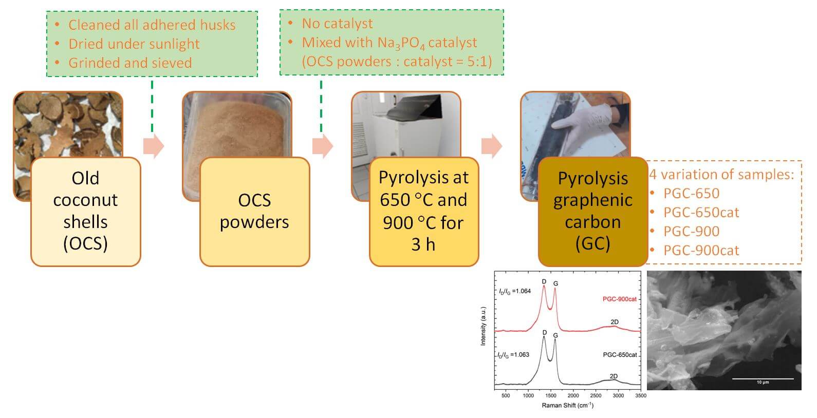
In a single-step pyrolysis route, the clean OCS is firstly ground and sieved to obtain powders. The refined OCS powder is then mixed with the phosphate salt of Na3PO4 as a catalyst with a mass ratio of 5:1. Samples without the addition of Na3PO4 catalyst are also prepared for comparison. The mixed powders are then pyrolyzed inside a sealed quartz tube at 650°C and 900°C for 3 h with a heating rate of 10°C/min. The pyrolysis temperature is determined based on the thermogravimetry analysis of coconut shells reported in our previous study [20], in which biomass degradation mostly takes place below 400°C. During the heating process, the temperature is held at 350°C for 1 h to ensure the decomposition of celluloses. For convenience, we mention the samples as pyrolysis graphenic carbon (PGC), in which PGC-650 and PGC-900 refer to those that are heated at 650°C and 900°C without the catalyst, respectively, and PGC-650cat and PGC-900cat for those with the addition of Na3PO4 catalyst. A schematic diagram of the route is summarized in Fig. 1.

Figure 1: A schematic diagram of the single pyrolysis route of PGC from OCS
In the two-step thermal reduction method, clean OCS is firstly burned in the air for 1 h to form charcoals, which are then ground and sieved to get homogeneous charcoal powders. The thermal reduction process is performed by heating the charcoal powders at 600°C (GC600), 800°C (GC800), and 1000°C (GC1000) in the air for 5 h. Liquid exfoliations in a chloric acid (HCl 1 M) solution are then employed, followed by a centrifugation process to separate the obtained dispersion. Finally, the resulting paste is dried to get the powdered sample. The detailed route is reported in [20].
Several characterization techniques are used to investigate the structures of the obtained samples. X-ray powder diffraction (XRD, X’pert Malvern Panalytical, Cu-Kα, λ = 1.5406 Å) is employed to examine phases formed in samples. The morphology of the samples is observed using a scanning electron microscope (SEM) equipped with energy-dispersive X-ray (EDX) to inspect elements contained in the samples. Raman spectroscopy (Horiba Scientific LabRam HR, 250 nm laser) is employed within the Raman shift range of 250–3500 cm−1 to evaluate graphitic and disordered structures in the samples. The masses of raw materials and the obtained products are weighed, and the yield percentage is determined by the mass ratio of the product and raw materials.
Electrical resistance is measured using our designed setup as illustrated in Fig. 2. As much as 0.5 g of the powder samples is put inside a container, which is then pressed with a die press connected to the container. The same pressure of 10 Nm is applied during the measurement. Each end of the container is connected to a digital multimeter. This setup enables a quick and simple test for a small-to-medium industry of GC.

Figure 2: The designed setup for the measurement of electrical resistance of powder samples
3.1 Results of a Single-Step Pyrolysis Method
A single pyrolysis method offers a convenient way to produce GC from OCS in large quantities. Yields produced by this route are relatively substantial compared to those synthesized via a chemical-assisted wet method [20]. An electrochemical exfoliation of graphite can produce graphene with high yield [33], but it is challenging for industrial-scale production because of its complicated setup and the use of electrolytes. The single pyrolysis step provides an environmentally friendly approach since no dangerous chemical compounds are involved during the process. Table 1 summarizes the yields of each sample obtained by the single pyrolysis route. A yield of approximately 24%–28% is achieved by employing this synthesis route. The lower pyrolysis temperature (650°C) tends to produce a slightly larger yield than the higher one (900°C) as more sample contents decompose at high temperatures.

The electrical resistance of the samples varies by temperature, which is ~10 times lower at 900°C than those at 650°C. As the mass of the sample, the applied pressure, and the container size are constant in the measurement and by assuming a relatively similar contribution of grain boundaries of the pressed powders inside the container, the electrical resistivity is proportional to the resistance, while the electrical conductivity is inversely proportional to the resistivity. It implies that the samples pyrolyzed at 900°C have higher electrical conductivity compared to those pyrolyzed at 650°C. This could indicate that there are more graphene-like layers in PGC-900 and PGC-900cat than those in PGC-650 and PGC-650cat.
Fig. 3 shows XRD patterns of the samples prepared by a single pyrolysis route. Broad peaks at ~24° and ~43° are observed in all samples, which are typical patterns of GC. A secondary phase of KCl salt (JCPDS card no. 41–1476 [34]) is detected in PGC-650 and PGC-650cat. This salt is likely formed because coconut shells naturally contain Na, K, Cl, and Ca elements as confirmed by EDX analysis. Such salt can be removed by a washing process in a dilute acid solution [16]. The absence of the KCl phase in PGC-900 is most likely due to the melting of this salt at ~770°C [35]. PGC-900cat, on the contrary, shows a pronounced impurity phase that corresponds to NaCl (JCPDS card no. 78-0751 [36]). The formation of NaCl salt possibly relates to the use of a Na3PO4 catalyst which partially melts at ~900°C and reacts with chloride presented in OCS.

Figure 3: XRD patterns of the samples obtained by a single-step pyrolysis method
Morphologies of the samples are displayed in Fig. 4. All samples show a stacked layered structure with a relatively wide lateral area. A small amount of a porous structure is observed in PGC-650 and PGC-650cat. At the 900°C pyrolysis, layers become thinner than those of the 650°C samples, indicated by their more transparent feature. This change signifies that a thermal reduction occurs as temperature increases, causing a morphological transformation from a porous, thick flake to transparent thin layers–a feature of GC. By looking at SEM images, the role of the catalyst seems not to be so remarkable. The relative contents of C and O in samples are condensed in Table 2. The relative percentage of C element slightly enhances at 900°C. In PGC-900cat, other elements including Na, Cl, K, and Ca are detected. The C/O ratio increases at 900°C indicating an enhancement of thermal stability and a reduction of oxygen functionalities which are related to a decrease in the yield produced.

Figure 4: SEM images of (a) PGC-650, (b) PGC-650cat, (c) PGC-900, and (d) PGC-900cat. Arrows in (a) and (b) indicate a porous structure
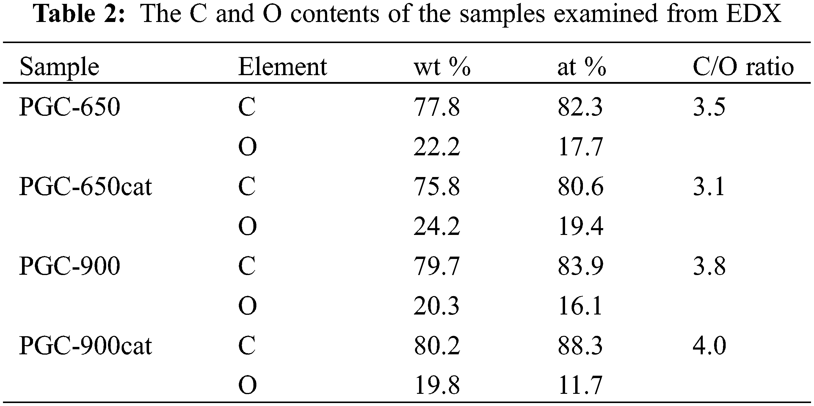
Fig. 5 presents Raman spectra of PGC-650cat and PGC-900cat, showing the presence of D-, G-, and 2D peaks. The D-peak relates to a disordered or defective structure, the G-peak describes a graphitic structure of sp2 carbon hybridization, and the 2D-peak is a characteristic of two-dimensional graphenic structures [37]. The intensity ratio of the D- and G-peaks (ID/IG) is almost the same, approximately 1.06 for both PGC-650cat and PGC-900cat. The ID/IG ratio reflects a structural disorder in graphene-like compounds [38]. The value of ~1.06 signifies that the disordered state is rather prominent than the graphitic structure. The 2D-peak has a broad feature with the I2D/IG ratio of ~0.1, indicating multilayered GC which confirms the observed SEM images.

Figure 5: Raman spectra of PGC-650cat and PGC-900cat
3.2 Comparison with Results of a Two-Step Heat Treatment Method
We briefly review the results of a two-step heat treatment method from our previous studies for comparison. This method involves the preparation of OCS-charcoals by a burning process before performing the second heat treatment. A comprehensive study of the sample structures was reported in [20]. The LPE procedure carried out in HCl 1 M solution after the heat treatment results in the absence of secondary phases. An increase in the applied temperature in the second heat treatment causes a decrease in oxygen functional groups, the creation of defects, and a reformation of 2D structure. The obtained samples have a sheet-like structure with crumple surfaces, showing a mixed 2D and 3D feature, and a porous characteristic with the size of nano-to-micrometer [20]. These findings are consistent with the current data displayed in Fig. 6. A stacked layer with a porous trait was observed in GC-600, GC-800, and GC-1000. The TEM image of GC-800 confirms stacking sheets in the sample, in which some parts look thinner than others. GC layers of GC-600, GC-800, and GC-1000 samples are relatively thick compared to those obtained by a single pyrolysis route at 900°C, but their feature is generally like those resulting at 650°C, having pores on their surfaces. Despite the temperature applied to form GC-1000 being higher than the 900°C pyrolysis, the GC-1000 still has thicker and more porous layers than PGC-900 and PGC-900cat. This could indicate that a transformation to a thinner GC layer occurs slowly when OCS is burned first to form charcoals or amorphous carbon before performing the second heat treatment.

Figure 6: SEM images of (a) GC-600, (b) GC-800, and (c) GC-1000 obtained from the two-step heat treatment method. Arrows in (a), (b), and (c) show a porous structure. (d) TEM image of GC-800. Arrows in (a–c) indicate a porous structure
Fig. 7 presents the particle size distribution of GC-800 estimated by a particle size analyzer (PSA). Two peaks at the particle size of approximately 200 and 6000 nm (6 μm) are obtained, in which the intensity of the first is more obvious than the latter. It indicates that the size of particles is mostly in a few hundred nanometres, and a small number of them are micro-sized particles. The size is significantly smaller compared to that observed in the SEM image (Fig. 6b). This could occur because only small particles dispersed in distilled water are detected and measured by PSA, while SEM observes precipitate powders. TEM images in Fig. 6d and the inset of Fig. 7 indeed show that GC-800 has some parts with a smaller particle and thinner layers. Through the two-step heat treatment followed by liquid phase exfoliation (LPE), the sample experiences a reduction in lateral sizes, from a few micro-to-hundreds of nanometers, and a thinning in layer thickness as indicated by a yellow arrow in the inset of Fig. 7. This result is consistent with the previous study of LPE route in acid solution [39]. Moreover, the two-step heat treatment method also generates a significant number of porous or holes as a nature of holey GC.

Figure 7: Particle size distribution of GC-800. Inset is the TEM image of GC-800. The arrow indicates a thinner layer part of the holey GC-800
Based on all the presented data above, one can point out that the single pyrolysis route offers a simple method to synthesize GC from coconut shells with a high yield, which is suitable for large-scale production. The obtained GC has relatively thinner layers and fewer pores compared to that resulting from the two-step heat treatment. However, secondary phases generated due to the intrinsic contents of raw materials and the addition of catalyst remain in the samples. These impurity phases can either be maintained or removed depending on their desired property for a certain application. Further, LPE can be implemented to remove impurities and thinning layers. However, this procedure sometimes generates a layer agglomeration. Agglomeration of GC layers somehow can create porous, enhance specific surface area, and provide more active sites. Therefore, it can be applied to enhance the performance of supercapacitors, efficiency of catalytic reaction, sensitivity of sensors, and adsorption capability of water purification [11]. Although the two-step heat treatment method results in a thicker sheet, it proposes a cleaner GC sample with a holey feature which is a potential for energy storage applications.
This study shows that the single pyrolysis method provides a simple and environmentally friendly approach to preparing GC from coconut shells with a high yield, hence is appropriate for large-scale production. The yield of GC slightly decreases by increasing the pyrolyzed temperature applied. A thinner GC layer with a less porous feature and an enhancement in the electrical conductivity is achieved by the pyrolysis at 900°C. The C/O ratio is relatively higher in the samples pyrolyzed at 900°C (PGC-900 and PGC-900cat) than those pyrolyzed at 650°C (PGC-650 and PGC-650cat). The addition of Na3PO4 catalyst has no significant effects on the GC structures obtained by this synthesis route, instead, it arouses the formation of secondary phases. Raman spectroscopy confirms a multilayer feature of GC and a similar level of structural disorder in PGC-650cat and PGC-900cat. The single pyrolysis route generates thinner GC sheets compared with the two-step heat treatment followed by the LPE procedure, yet the latter method offers a formation of clean samples with a porous or holey nature. Further applications of the obtained GC, such as for supercapacitors, batteries, adsorption materials, and concrete reinforcement, are worth exploring.
Acknowledgement: This work is supported by the program of Matching Fund Kedaireka 2023 in collaboration with PT. Graphene Nanomaterial Consulting.
Funding Statement: This work is funded by the Matching Fund Kedaireka Program Based on the Decision Letter No. 15/E1/PPK/KS.03.00/2023 dated 26 April 2023 and the Cooperation Agreement No. 114/E1/HK.02.02/2023.
Author Contributions: Study conception and design: D. Darminto, R. Asih, A. Y. Dias, P. Untoro; data collection: H. Nurdiansah, R. Asih, A. T. Setiawan, A. Sholih; analysis and interpretation of results: R. Asih, H. Nurdiansah, D. Darminto, M. Zainuri, D. S. Khaerudini; draft manuscript preparation: R. Asih, H. Nurdiansah, D. Darminto. All authors reviewed the results and approved the final version of the manuscript.
Availability of Data and Materials: Data available within the article. Requests for materials should be addressed to R.A. or D.
Conflicts of Interest: The authors declare that they have no conflicts of interest to report regarding the present study.
References
1. Tsang CHA, Huang H, Xuan J, Wang H, Leung DYC. Graphene materials in green energy applications: recent development and future perspective. Renew Sustain Energy Rev. 2020 Mar;120:109656. [Google Scholar]
2. Pastrana-Martínez LM, Morales-Torres S, Figueiredo JL, Faria JL, Silva AMT. Graphene photocatalysts. In: Multifunctional photocatalytic materials for energy. Duxford, UK: Elsevier; 2018. p. 79–101. [Google Scholar]
3. Han S, Sun J, He S, Tang M, Chai R. The application of graphene-based biomaterials in biomedicine. Am J Transl Res. 2019;11(6):3246–60. [Google Scholar] [PubMed]
4. Papageorgiou DG, Kinloch IA, Young RJ. Mechanical properties of graphene and graphene-based nanocomposites. Prog Mater Sci. 2017 Oct;90:75–127. [Google Scholar]
5. Sang M, Shin J, Kim K, Yu KJ. Electronic and thermal properties of graphene and recent advances in graphene based electronics applications. Nanomaterials. 2019;9(3):1–33. [Google Scholar]
6. Castro Neto AH, Guinea F, Peres NMR, Novoselov KS, Geim AK. The electronic properties of graphene. Rev Mod Phys. 2009 Jan 14;81(1):109–62. [Google Scholar]
7. Falkovsky LA. Optical properties of graphene. J Phys Conf Ser. 2008 Oct 1;129:012004. [Google Scholar]
8. Zhang S, Wang H, Liu J, Bao C. Measuring the specific surface area of monolayer graphene oxide in water. Mater Lett. 2020 Feb;261:127098. [Google Scholar]
9. Saeed M, Alshammari Y, Majeed SA, Al-Nasrallah E. Chemical vapour deposition of graphene-synthesis, characterisation, and applications: a review. Molecules. 2020;25(17):1–62. [Google Scholar]
10. Tarcan R, Todor-Boer O, Petrovai I, Leordean C, Astilean S, Botiz I. Reduced graphene oxide today. J Mater Chem C Mater. 2020;8(4):1198–224. [Google Scholar]
11. Ray SC. Application and uses of graphene oxide and reduced graphene oxide. In: Applications of graphene and graphene-oxide based nanomaterials. Waltham, USA: Elsevier; 2015. p. 39–55. [Google Scholar]
12. Chua CK, Pumera M. Chemical reduction of graphene oxide: a synthetic chemistry viewpoint. Chem Soc Rev. 2014;43(1):291–312. [Google Scholar] [PubMed]
13. Acik M, Lee G, Mattevi C, Pirkle A, Wallace RM, Chhowalla M, et al. The role of oxygen during thermal reduction of graphene oxide studied by infrared absorption spectroscopy. J Phys Chem C. 2011 Oct 13;115(40):19761–81. [Google Scholar]
14. Shao Y, Wang J, Engelhard M, Wang C, Lin Y. Facile and controllable electrochemical reduction of graphene oxide and its applications. J Mater Chem. 2010;20(4):743–8. [Google Scholar]
15. Pulido A, Concepción P, Boronat M, Botas C, Alvarez P, Menendez R, et al. Reconstruction of the carbon sp2 network in graphene oxide by low-temperature reaction with CO. J Mater Chem. 2012;22(1):51–6. [Google Scholar]
16. Darminto, Koike Y, Asih R, Kurniasari, Baqiya MA, Mustofa S, et al. Enhanced magnetism by temperature induced defects in reduced graphene oxide prepared from coconut shells. IEEE Trans Magn. 2018 Oct;54(10):1–5. [Google Scholar]
17. Rai S, Bhujel R, Biswas J, Swain BP. Reduced graphene oxide for advanced energy applications. In: Nanostructured materials and their applications. Singapore: Springer; 2021. p. 115–30. [Google Scholar]
18. Yan Y, Meng Y, Zhao H, Lester E, Wu T, Pang CH. Miscanthus as a carbon precursor for graphene oxide: a possibility influenced by pyrolysis temperature. Bioresour Technol. 2021 Jul;331:124934. [Google Scholar] [PubMed]
19. Jara AD, Betemariam A, Woldetinsae G, Kim JY. Purification, application and current market trend of natural graphite: a review. Int J Min Sci Technol. 2019 Sep;29(5):671–89. [Google Scholar]
20. Ristiani D, Asih R, Astuti F, Baqiya MA, Kaewhan C, Tunmee S, et al. Mesostructural study on graphenic-based carbon prepared from coconut shells by heat treatment and liquid exfoliation. Heliyon. 2022 Mar;8(3):e09032. [Google Scholar] [PubMed]
21. Purwandari E, Nur’aini N, Firdaus AA, Sholih A, Asih R, Subekti A, et al. N-doped graphenic carbon derived from coconut shell as n-type semiconducting layer. Mater Sci Forum. 2023 Jul 27;1094:117–22. [Google Scholar]
22. Ajien A, Idris J, Md Sofwan N, Husen R, Seli H. Coconut shell and husk biochar: a review of production and activation technology, economic, financial aspect and application. Waste Manag Res. 2023 Jan;41(1):37–51. [Google Scholar] [PubMed]
23. Yang K, Peng J, Srinivasakannan C, Zhang L, Xia H, Duan X. Preparation of high surface area activated carbon from coconut shells using microwave heating. Bioresour Technol. 2010 Aug;101(15):6163–9. [Google Scholar] [PubMed]
24. Li Q, Ma CL, Zhang PQ, Li YY, Zhu X, He YC. Effective conversion of sugarcane bagasse to furfural by coconut shell activated carbon-based solid acid for enhancing whole-cell biosynthesis of furfurylamine. Ind Crops Prod. 2021 Feb;160:113169. [Google Scholar]
25. Lee KC, Lim MSW, Hong ZY, Chong S, Tiong TJ, Pan GT, et al. Coconut shell-derived activated carbon for high-performance solid-state supercapacitors. Energies. 2021 Jul 27;14(15):4546. [Google Scholar]
26. Khambali I, Priyanto B, Asih R, Anjelh Baqiya M, Mahyiddin Ramli M, Huda Osman N, et al. N-doped rGO-like carbon prepared from coconut shell: structure and specific capacitance. J Renew Mater. 2023;11(4):1823–33. [Google Scholar]
27. Dastgheib SA, Salih H, Ilangovan T, Mock J. NO oxidation by activated carbon catalysts: iimpact of carbon characteristics, pressure, and the presence of water. ACS Omega. 2020 Aug 25;5(33):21172–80. [Google Scholar]
28. Güngör A, Önenç S, Uçar S, Yanik J. Comparison between the “one-step” and “two-step” catalytic pyrolysis of pine bark. J Anal Appl Pyrolysis. 2012 Sep;97:39–48. [Google Scholar]
29. Pahnila M, Koskela A, Sulasalmi P, Fabritius T. A review of pyrolysis technologies and the effect of process parameters on biocarbon properties. Energies. 2023 Oct 3;16(19):6936. [Google Scholar]
30. Bahcivanji L, Gascó G, Paz-Ferreiro J, Méndez A. The effect of post-pyrolysis treatment on waste biomass derived hydrochar. Waste Manage. 2020 Apr;106:55–61. [Google Scholar]
31. Zarzycki PK. Pure and functionalized carbon based nanomaterials. Boca Raton: CRC Press, Taylor and Francis Group; 2020. [Google Scholar]
32. Bledzki AK, Mamun AA, Volk J. Barley husk and coconut shell reinforced polypropylene composites: the effect of fibre physical, chemical and surface properties. Compos Sci Technol. 2010 May;70(5):840–6. [Google Scholar]
33. Tripathi P, Prakash Patel CHR, Dixit A, Singh AP, Kumar P, Shaz MA, et al. High yield synthesis of electrolyte heating assisted electrochemically exfoliated graphene for electromagnetic interference shielding applications. RSC Adv. 2015;5(25):19074–81. [Google Scholar]
34. Dai F, Zai J, Yi R, Gordin ML, Sohn H, Chen S, et al. Bottom-up synthesis of high surface area mesoporous crystalline silicon and evaluation of its hydrogen evolution performance. Nat Commun. 2014 Apr 10;5(1):3605. [Google Scholar]
35. Zhou D, Dong J, Si Y, Zhu F, Li J. Melting curve of potassium chloride from in situ ionic conduction measurements. Mineral. 2020 Mar 9;10(3):250. [Google Scholar]
36. Nickels JE, Fineman MA, Wallace WE. X-ray diffraction studies of sodium chloride-sodium bromide solid solutions. J Phys Colloid Chem. 1949 May 1;53(5):625–8. [Google Scholar]
37. Li Z, Deng L, Kinloch IA, Young RJ. Raman spectroscopy of carbon materials and their composites: graphene, nanotubes and fibres. Prog Mater Sci. 2023 Jun;135:101089. [Google Scholar]
38. Saito R, Jorio A, Souza Filho AG, Grueneis A, Pimenta MA, Dresselhaus G, et al. Dispersive raman spectra observed in graphite and single wall carbon nanotubes. Physica B Condens Matter. 2002 Oct;323(1–4):100–6. [Google Scholar]
39. Baqiya MA, Nugraheni AY, Islamiyah W, Kurniawan AF, Ramli MM, Yamaguchi S, et al. Structural study on graphene-based particles prepared from old coconut shell by acid-assisted mechanical exfoliation. Adv Powder Technol. 2020 May;31(5):2072–8. [Google Scholar]
Cite This Article
 Copyright © 2024 The Author(s). Published by Tech Science Press.
This work is licensed under a Creative Commons Attribution 4.0 International License , which permits unrestricted use, distribution, and reproduction in any medium, provided the original work is properly cited.
 Downloads
 Citation Tools