
 Submit a Paper
 Propose a Special lssue
 Open Access
ARTICLE

Bio-PCM Panels Composed of Renewable Materials Interact with Solar Heating Systems for Building Thermal Insulation
Laboratory of Energy and Materials: LabEM-LR11ES34, University of Sousse, Hammam Sousse, Tunisia
* Corresponding Author: Fadhel Aloulou. Email:
(This article belongs to the Special Issue: Special Issue in Celebration of JRM 10 Years)
Journal of Renewable Materials 2024, 12(4), 771-798. https://doi.org/10.32604/jrm.2024.047022
Received 22 October 2023; Accepted 18 December 2023; Issue published 12 June 2024
 View Full Text
 Download PDF
Abstract
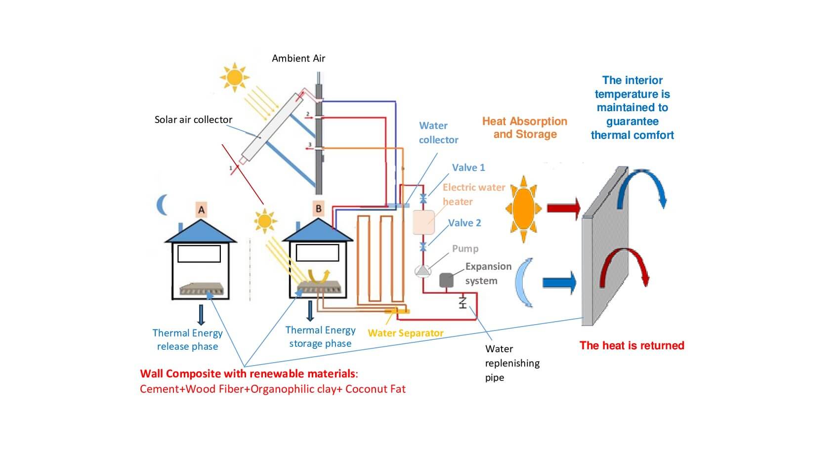
This article aims to present the feasibility of storing thermal energy in buildings for solar water heating while maintaining the comfort environment for residential buildings. Our contribution is the creation of insulating composite panels made of bio-based phase change materials (bio-PCM is all from coconut oil), cement and renewable materials (treated wood fiber and organic clay). The inclusion of wood fibers improved the thermal properties; a simple 2% increase of wood fiber decreased the heat conductivity by approximately 23.42%. The issues of bio-PCM leakage in the cement mortar and a roughly 56.5% reduction in thermal conductivity with bio-PCM stability in composite panels can be resolved by treating wood fibers with an adjuvant by impregnating them in bio-PCM in the presence of the treated clay generated. Clay and wood fiber were treated with adjuvants that are both biological and environmentally acceptable, as confirmed by FTIR spectroscopy. The heat transfer bench (DIDATEK) showed a decrease in thermal conductivity. By using differential scanning calorimetric (DSC) analysis, the investigation of thermal stability and enthalpy during two heating cycles of pure bio-PCM and composite bio-PCM was validated. The novel renewable material was used to create composite panels for the trial prototype, which took the shape of a component attached to the solar heating system, 33.57% less heat was lost, according to the heat transfer research. The outcomes demonstrated the possibility of replacing traditional electric water heating in residential buildings with solar water heating systems.Graphic Abstract
Keywords
Nomenclature
| CTAB | Cetyltrimetylammoniium bromide |
| PCM | Phase change material |
| FTIR | Fourier transform-infrared spectroscopy |
| DSC | Differentitial scanning calorimeter |
| XRD | X-ray diffraction |
| NaOH | Soduim hydroxide |
| H2SO4 | Sulfuric acid |
| HCL | Hydrochloric acid |
| NaCl | Soduim chloride |
| WF | Wood fiber |
| WFT | Wood fiber treated |
| OPC | Ordinary Portland Cement |
| P-CR | Reference cementitious panel |
| P-CW | Wood cementitious panel |
| P-CPCM | Phase change cementitious panel |
| P | Porosity (%) |
| Abs | Water uptake (%) |
| λ | Thermal conductivity (W/m-.K-°) |
| R | Thermal resistance (m2.k/W) |
| QH | Total Heat loss from the envelope (Wh) |
| T | Temperature (°C) |
| t | Time (h) |
| S | Surface (m2) |
| G | Total heat loss coefficient (W/k°) |
The potential impact of phase change materials (PCMs) for thermal energy storage on all fields of science and technology has drawn a lot of attention to this young field of study. It is advantageous to numerous research and application areas, including solar energy, intelligent textiles, heat transfer media, and intelligent buildings [1]. Due to global warming and the depletion of fossil fuels, the search for novel solutions that use less energy and are cleaner than existing ones has become imperative. Latent thermal storage is one of the methods being considered to lower consumption [2]. Due to the excellent phase change behavior and large heat storage capacity of this method, it shows promise in this field. During melting and solidification at certain temperatures, phase change materials (PCM) can be used to store and release large amounts of heat with smaller volumes. In fact, PCMs improve solar energy consumption and reduce temperature changes as a result of the solid-liquid phase transition [3,4]. Comprehensive analyses of PCMs and their applications are available, and PCM research has gradually risen in recent years [5–7]. The development of phase change materials (PCMs) with high energy storage density and recyclable solid-liquid phase behavior is thus one of the key objectives [8–10]. Due to their stable physical and chemical properties, high biosafety (e.g., non-toxic, odorous and non-irritating) and adjustable phase change temperature, renewable latent heat storage biomaterials (oil coconut: bio-PCM) have attracted a lot of interest. Hexadecanoic and octadecanoic acid esters, with fatty alcohols with chains lengths between 38 and 52 and 46 and 54 carbon atoms, respectively, make up the majority of the coconut oil’s chemical makeup [11]. Because of these molecular structure characteristics, which result in a relatively high enthalpy of fusion, coconut oil is a promising candidate for bio-PCM [12], which is a form of energy storage. However, leakage during the energy storage process restricts the uses of coconut oil (bio-PCM) Low thermal conductivity, meanwhile, also speeds up the transfer and conversion of solar thermal energy [13,14]. To keep coconut oils and organophilic clay stable during application, combine them with wood fibers and helpful elements. In addition to being fastened on the wood fibers and integrated between the layers of the organophilic clay in a compact condition even after fusing, leakage of the coconut oil is avoided. Wood fiber-reinforced cementitious matrix composite mortars are simple to work with and offer a variety of unique benefits. The most popular way for combining coconut oil with organophilic clays to stabilize bio-PCM appears to be impregnation on wood fibers [15–17]. For instance, Iba et al. [18] investigated the thermal and thermomechanical characteristics of stabilized phase change materials. To solve these issues, shape-stable coconut oil materials (bio-PCM) must be created [19]. Porous P-CPCM can be prepared from renewable biomass or waste biomass, which not only reduces the preparation cost of solar thermal energy storage materials, but also accelerates the energy revolution and reduces pollution from both the use of fossil fuels and the disposal of biomass waste [10]. At the moment, coconut oils (bio-PCM) are gaining a lot of attention as a natural filler for matrices like poly (lactic acid: LA) [20] and polypropylene [9]. These particles’ organic components include celluloses, hemicelluloses, lignins, and fatty acids [20,21]. These substances are well known for giving renewable bio-materials a high degree of rigidity and flexibility [22]. Due to high polysaccharide, phenolic, and fatty acid content as well as the production of several crucial substances, such as coconut oil, coconut has also been used [23]. However, due to their strong hydrophobicity, coconut oils, like other organic fillers, have poor compatibility with water, which limits their compatibility with the majority of (hydrophilic) cement matrices, resulting in a poor filler/filler interface matrix, causing the formation of bio-composites with poor mechanical performance, which limits their widespread use.
To create PCM bio-composites from the renewable materials, coconut oils can be combined with other biomasses like wood fibers or organophilic clays by adsorption or impregnation between the clays’ leaves, which are exfoliated by cationic surfactants of the CTAB type [22,24]. Coconut oils demonstrated a high rate of impregnation of bio-PCMs made of wood fibers, which gives the substance a high latent heat capacity [25]. Other studies [26] demonstrated that adding graphene oxide to CPCM can significantly enhance the absorption of coconut oil onto polyethylene glycol while also enhancing thermal conductivity. It is still challenging to increase the thermal conductivity and adsorption rate of coconut oils for inexpensive PCMs as a renewable materials. Coconut oils showed a high rate of wood fiber-based CPCM impregnation and a high latent heat capacity. Typically, PCMs are combined with support materials to create shape-stabilized PCMs. However, the majority of these PCMs are produced using intricate processes and hazardous or corrosive chemicals, which results in high costs and environmental issues. As support materials, biopolymers have also been used for targeted applications in the plastics industry, for water treatment and for the building sectors. Natural resources that are abundant and renewable include wood fibers and organophilic clay. These materials have a variety of benefits including affordability, high biocompatibility, non-toxicity, and environmental friendliness [27]. Coconut oil can be converted quickly and sustainably without the need for cross-linking [28,29].
Research reports on the use of coconut oil as stabilized phase change materials are still uncommon, though, as of right now. The immobilization of cementitious matrix composite materials as phase change and heat storage materials when adding coconut oil in building sectors using concrete mortars must therefore be further researched. The current research work describes the methods related to the production of bio-CPCMs based on renewable raw materials in the quest for effective and sustainable PCMs. The objective is to develop bio-composite materials from renewable materials such as coconut oil, wood fibers, organic clay and cement as a matrix, and subsequently to test their thermal stability and their storage capacity after incorporation of microfibers, while examining the efficiency of solar heating systems.
It is important to note that the use of natural fibers has increased as a result of the development of environmentally friendly building materials. For instance, readily available, lightweight, and biodegradable fibers like sisal, flax, hemp, bamboo, and coir is available. The loss of mechanical properties that occurs when adding more organoclay is another of the material’s major drawbacks.
In this study, we make use of wood fiber and organophilic clay-reinforced composite materials made from concrete. In addition, we want to strengthen the connection between the matrix and the preexisting wood fiber and enhance the microstructure of the grid. It is intriguing to use the surfactant CTAB as an adjuvant to promote interaction by reacting with cement between wood fiber treated clay platelets, organoclay, and clay platelets. The use of organoclay has the advantage of enhancing the microstructures and properties of manufactured materials. In order to describe how hydrophobic wood fiber is, contact angle was used. Organoclay in powder form was also characterized using X-ray diffraction and FTIR. Organoclay was created mechanically using clay and cetyltrimethyl ammonium bromide (CTAB). Research and analysis are carried out on the physical properties and thermal conductivity of wood fiber reinforced cement composites. The study of thermal transfers was carried out using an experimental prototype containing a room connected to the solar heating system with cemented walls made with this new material. To our knowledge, this idea has not been studied extensively in the literature, a typical single-family home’s space heating load and domestic hot water demand should be satisfied by a solar system that includes wall panels and water tanks.
The bio-based phase change material (bio-PCM) commonly used for thermal energy storage in building applications in our work comes entirely from a commercial coconut oil. The coconut fruits were first separated from the nuts, washed and ground. Coconut oil was obtained from the fruit by extracting water from the crushed fiber and then roasting the extract to obtain oil. Coconut Oil is a white vegetable oil. Its melting temperature is around 23.53°C. Its respective latent heats of fusion and freezing were found to be 90.98 and 91.78 J/g.
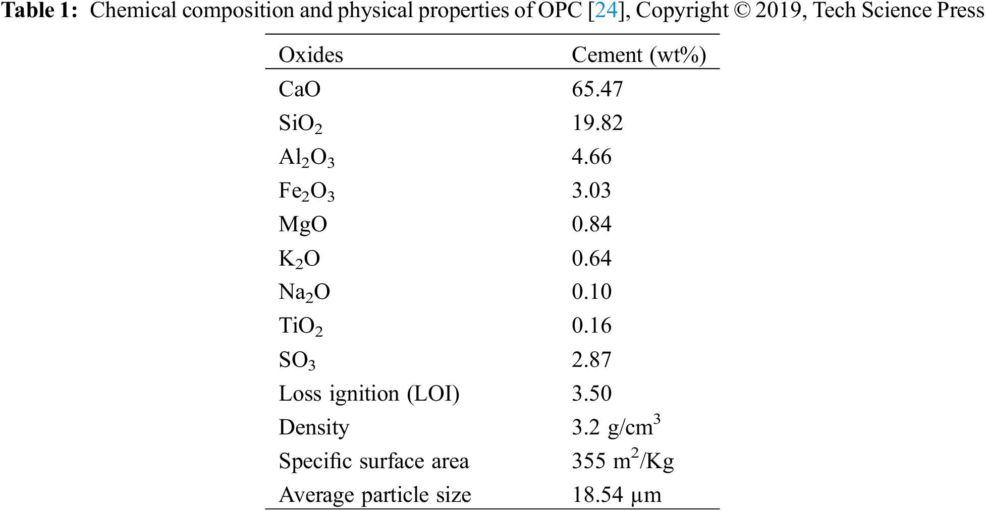
The matrix used in this work for the manufacture of composites is an ordinary Portland cement, manufactured by the Enfidha cement factory according to the Tunisian standard NT EN 13748-2:2004 and the European standard EN 197-1:2011 (Table 1).
As part of the recovery of industrial waste, we used wood fibers as a support for the bio-PCM. These fibers are extracted from carpentry waste, they are considered thermal and acoustic insulating, they are characterized by their high density and their low thermal conductivity in addition they are abundant, renewable and inexpensive. In order to make our material developed as a material having a heat storage aspect, a treatment of wood fires by impregnation using coconut oil (purity 99%), was purchased from M/s SD Fine Chem Limited which is an ecological bio-material having a character of bio-based phase change materials (bio-PCM), was necessary. To avoid leaks of bio-PCM during cooling-heating cycles, we used clay treated with a cationic surfactant (CTAB) in order to improve their stability and increase their power of retention of the bio-PCM which remains trapped between the leaves of clays treated with cationic surfactants. The clay minerals used in this work are extracted from Tunisian geological deposits.
2.2 Particle Size Determination
Malvern Nano-zetasizer ZS (Malvern, UK) with a fixed scattering angle of 173° was used to measure the hydrodynamic diameters and particle size diameters of sand at 20°C. Before beginning the measurements, there was no dilution of the dispersions [30]. In order to compare the various particles, dynamic light scattering measurements provided a Z-average size (Fig. 1).
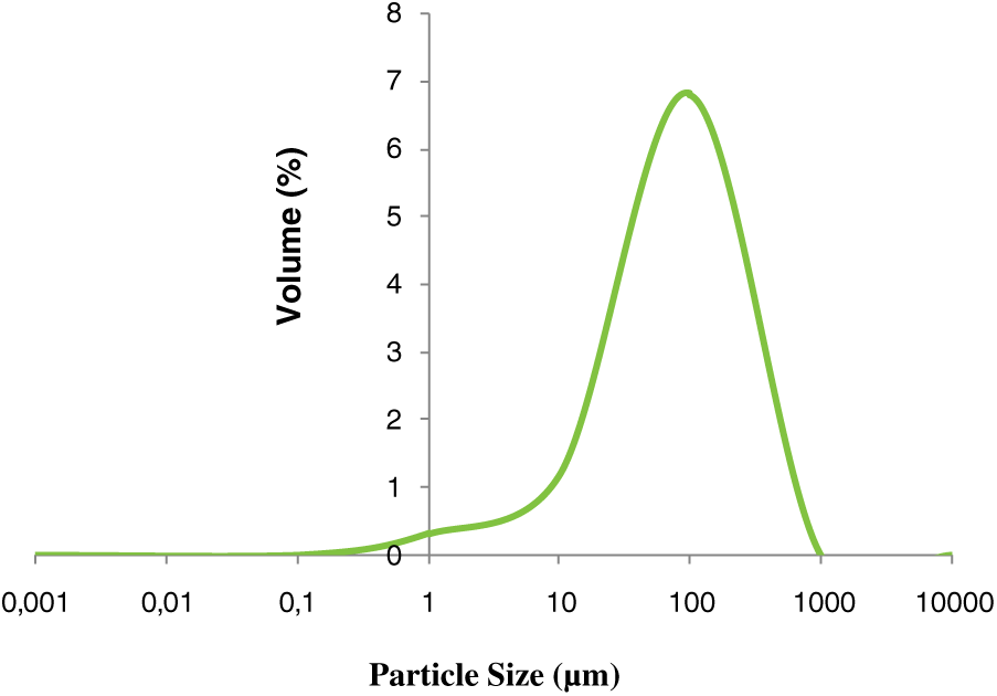
Figure 1: Particle size distribution of silica sand [22], Copyright © 2019, Tech Science Press
Fig. 1 shows that the average volume of silica powder milled for 2 h was 73.53 μm. The specific surface of quartz sand was 0.83 m2g−1.
To improve the pore size, affinity and adsorption of wood fibers to cementitious mortars, the fibers underwent chemical treatment with soda. This process gives rise to wood fibers which are rich in cellulose and which are devoid of lignin, an aspect more compatible with construction materials based on cementitious matrix. This treatment was carried out by mixing 300 g of sifted wood fibers of size 250 µm with an alkaline solution with a concentration of 2 mol/L (by dissolving 123 g of NaOH soda in 1.5 l of distilled water) in a beaker of 2000 ml and placed under magnetic stirring on a hot plate for 3 h is maintained at a constant temperature at 60°C in order to eliminate the lignin and to make these wood fibers treated (WFT) with soda more compatible and more stable with the cement matrix achieves an interaction with calcium cations Ca2+ and subsequently an improvement in compressive strength. These fibers were then filtered for 24 and rinsed four times with distilled water to remove excess NaOH, and to have a neutral solution, six drops of acetic acid (2 M) are added NaOH, and to have a neutral solution, six drops of acetic acid (2 M) are added.
Natural clay powders were ground in a mortar then sieved at 250 µm and rinsed with distilled water. The clay obtained is chemically treated to increase adhesion and interaction between the different organic materials used (wood fiber, coconut oil and cement). This chemical treatment acts on the specific surface, on the size of the pores and on the exfoliation of the clay. The first step consists of mixing 600 g of cleaned clay with 1000 ml of H2SO4 sulfuric acid solution (1 M) with mechanical stirring at 80°C. Once the clay was completely dispersed, a simple filtration was carried out followed by washing with distilled water before being dried in the oven for 24 h, then ground again in a mortar. The separation of the sheets is ensured by the use of sodium ions (Na+, Cl−). For this, a solution of 1000 ml of NaCl (1 M) is prepared then mixed with the clay with continuous magnetic stirring for 4 h at room temperature. In order to remove Cl− ions, washing with distilled water is necessary. The clay was then dried in an oven at 105°C for 2 h and ground again. To ensure good adsorption of coconut oil (PCM) as well as good adhesion interaction of the treated wood fibers on the clay, an organophilic treatment with a cationic surfactant is applied to the clay in the following manner: A solution of 1000 mL of hydrochloric acid HCl (0.1 M) was first prepared in a 2000 mL beaker. The acid solution was brought to a temperature of 80°C with very slow stirring, and when the temperature stabilized, a cationic surfactant CTAB was added. The clay is then added to the resulting solution. After 3 h of magnetic stirring, the samples were successively rinsed with distilled water, filtered then dried at 80°C and ground.
The different composites were manufactured in five main steps:
-Evaluation of quantities in mass percentage of materials used for sample preparation (cement, sand, wood fiber, water, bio-PCM, organophilic clay).
-Preparation of molds as required.
-Homogenization of samples using a high-pressure homogenizer and placing in molds.
-Unmold the samples after 24 h.
-Air drying.
All the composites developed have a W/C ratio equal to 0.45 with a percentage of reinforcements incorporated in the cement matrix evaluated in relation to the total mass of binder and aggregates (cement + sand).
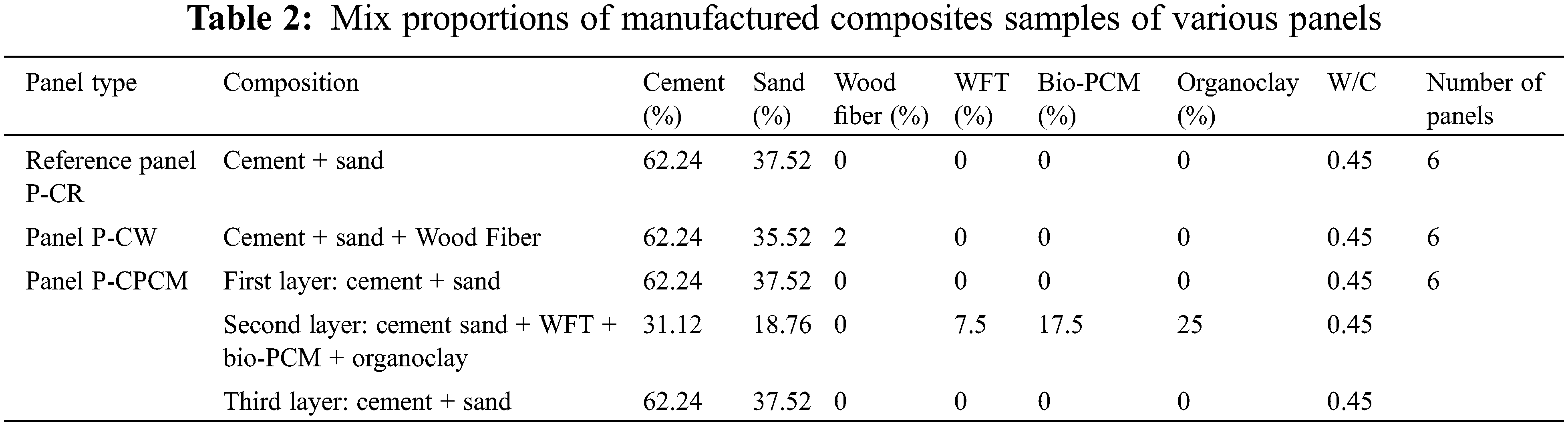
Three types of composite samples were developed in this study. Table 2 summarizes the configuration of each composite.
Depending on the need for use, two examples of forms were produced in this study (Table 3):
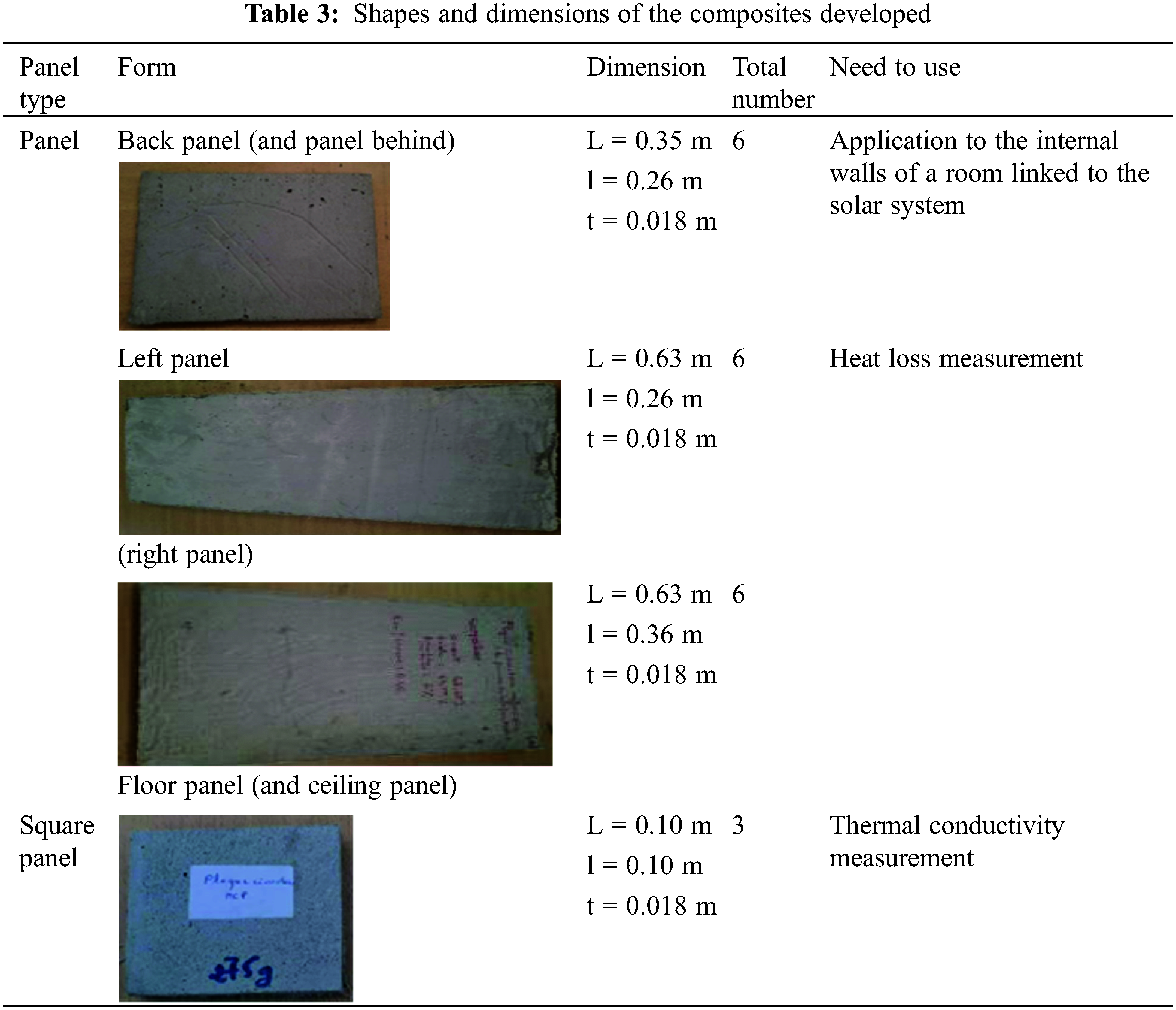
-For the measurement of the thermal conductivity of each composite, a square plate mold was prepared.
-For the energy study in the building and depending on the size of the parts linked to the solar system, 3 molds were prepared.
2.5.2 Preparation of the Bio-PCM-Composite
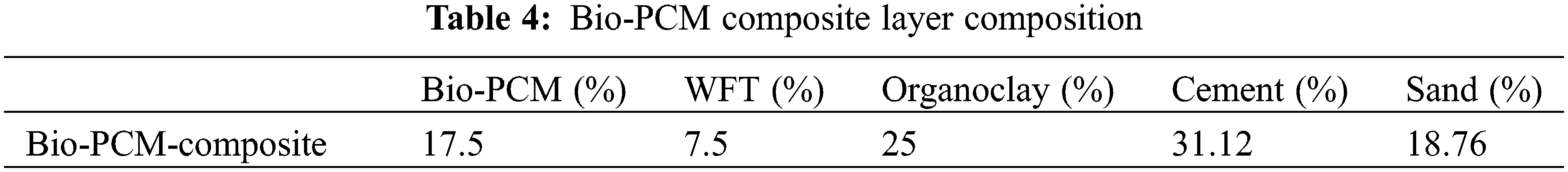
For the insulating layer (second layer) of the sandwich panel, the composition of the mortar mixture is made by adding the organophilic clay treated with the cationic surfactant CTAB and the wood fibers treated with coconut oil by impregnation as reinforcements in elaborate mortars. The mass percentage of bio-PCM, organophilic clay and treated wood added to the reference mortar is presented in Table 4. These quantities of bio-PCM were selected following a study and the results of our work on the thermal properties of concrete and cement mortar.
The development of the composite material was carried out by conditioning the bio-PCM by the direct incorporation method in stable form. In fact, the treated wood fiber (WFT) is mixed with coconut oil (bio-PCM) for 4 h. In order to promote saturated adsorption of bio-PCM, the composite material is placed in an oven at 35°C for 24 h. In order to eliminate bio-PCM leakage during phase change, organophilic clay was added to this composite material. Finally, this mixture is integrated with 50% by mass into the cement mortar. The processes of preparation of bio-PCM composite are showing in Fig. 2.
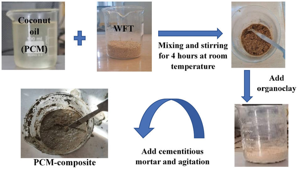
Figure 2: Process of preparation of a Bio-PCM composite
2.6 Evaluation of Composite Materials Characteristics
2.6.1 Infrared Fourier Transform Spectroscopy (FTIR)
To identify the functional groups of the materials studied, Fourier transform infrared spectroscopy is an effective method for our work.
A spectrophotometer (Perkin-Elmer BX II) operating in transmission mode with a resolution of 4 cm−1 in the range of 400–4000 cm−1 with a resolution of 4 cm−1 was used to produce the FTIR spectra from KBr pellets.
We used x-ray diffraction (XRD) to analyze the spectrum of the clay and to evaluate the difference between the crystallinity of natural wood fibers and treated wood fibers. Both fibers were identified using a Bruker D8 advanced diffractometer with CuKα (λ = 1.541 Å). Both fibers were scanned in the 2θ range from 5° to 80° at room temperature, with a step of 0.020° and an incidence angle equal 1°, using Cu-Kα radiation at 40 kV and 30 mA.
The crystallinity index (CrI) of the wood fiber was calculated according to Segal’s empirical method to determine the apparent crystallinity of cellulose (Eq. (1)):
2.6.3 Density and Porosity Determination of Composite
Each sample was first submerged in water for three hours in a vacuum chamber to determine the saturation mass, which was then used to calculate the porosity of the samples. The samples were weighed after they were saturated, and the weight of each sample was then recorded. The samples were then put in a 60°C oven to obtain dry matter, which was then measured. The Eq. (2) was then used to determine each sample’s porosity (v (%)):
The weight/volume proportion is known as bulk density. In order to achieve a constant weight, the composite samples were dried in a controlled oven at 70°C. Following that, the samples were accurately weighed with an electronic balance that had a resolution of about 10−4 g. The dimensions of the samples were measured with a vernier caliper that had a 0.02 mm accuracy margin of error. A medium, soil, or rock’s capacity to contain pores that is, voids can be described as having porosity. The volume of these voids divided by the total volume of the medium can be used to represent it.
After determining the water mass content (H) of a composite, the porosity is inferred. Eq. (3) provides the answer to this.
2.6.4 Contact Angle Measurements
A technique related to a liquid’s ability to spread out on a surface by wet ability is the measurement of the angle of contact. In order to characterize something, the basic idea is to measure the angle between the surface of the substratum and the profile of a liquid drop that has been dropped on it.
We used the angle of contact method in our research to determine whether the sample surface was hydrophilic or hydrophobic. In our instance, we used water, a polar solvent, as the liquid of measure of angle of contact; this liquid allows one to infer whether a surface is hydrophobic or hydrophilic.
According to the standard, which investigates how much a material weighs after being submerged in water, water absorption tests were conducted. After drying in an oven, the sample’s mass was calculated (w0). Water was used to submerge the dried samples. They are then briefly placed on a filter paper to release the trapped water. Wet sample mass (weight) is calculated. Eq. (4) is used to calculate the water uptake:
2.6.6 Analysis of Thermal Properties by DSC Differential Scanning Calorimetry
The latent heat and phase change temperature of pure bio-PCM and bio-PCM-composites were measured by using a differential scanning calorimetry (PerkinElmer DSC 4000). The temperature range was between −20°C and 100°C, with a heating and cooling rate of 10°C/min under the protective gas of high purity nitrogen (purity of 99.99%).
The thermal conductivity of all samples (Using square panel that were 10 × 10 × 1.8 cm) was determinate by heat transfer study unit DIDTEC (PTC 100). In fact, we measure several times the value of heat flow through the surface of the heating plate and the surface outside of the sample with the increase of the heating plate temperature and we take their averages (Eq. (5)):
which:
t: the thickness of the hotplate which is 6 · 10−3 m.
S: the surface of the hotplate which is 0.0625 m2.
P: the power consumed (P = ɸ = heat flow through the surface of the heating plate and the surface outside of the sample with the increase of the heating plate temperature).
Tc: the heating plate temperature.
Te: the external temperature of the sample (from elaborate plate).
2.7 Presentation of Solar Heating System
The experimental prototype used in our work is a solar heating system acquired by the Laboratory of Energy and Materials (LabEM) at ESSTHS University of Sousse-Tunisia, this system is presented by Fig. 3.
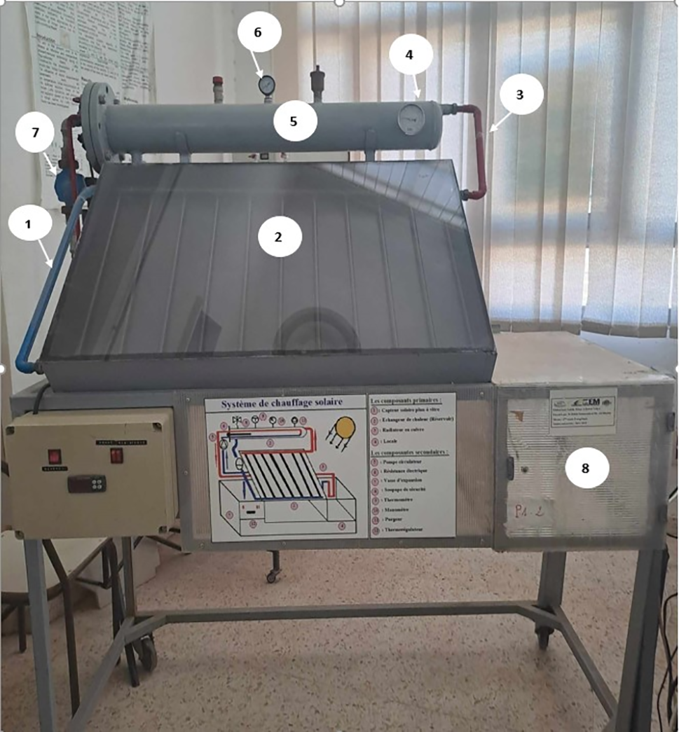
Figure 3: Solar heating system
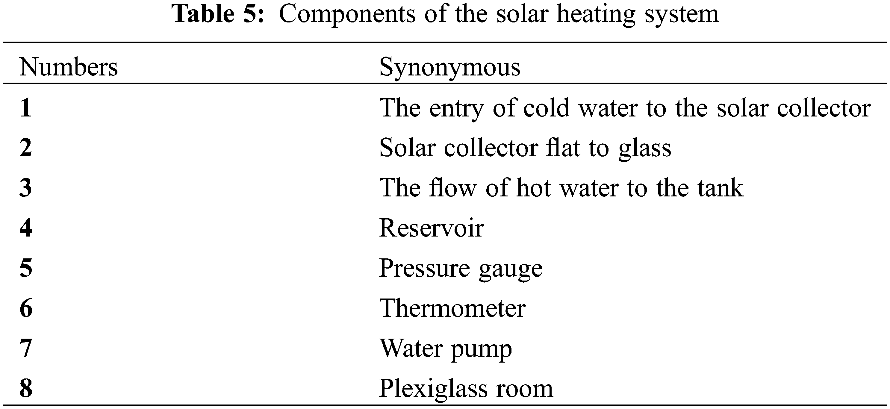
This experimental prototype unit is divided into two parts: water heater and solar energy conversion heating (Table 5). Our contribution is the design and development of internal coverings for all room walls measured by cement insulating panels and through probes it is possible to control and determine the amount of energy used to improve its energy efficiency.
2.8 Equation of Heat Loss from the Premises through the Different Composite Panels Developed
In order to establish the room heat loss equations which describe the physics of the problem, we pose the following hypotheses:
• Heat transfer in the room is unidirectional.
• The incident solar flux is uniform over the entire face of the enclosure.
• The effect of thermal bridges is negligible (no heat loss through corners, angles, etc.).
• No windows (no direct heat gain).
• No door.
To determine the heat loss from the envelope through the panels produced for a specific period of time, we use the following Eq. (6):
We assume that the term
Eq. (6) becomes:
with
For our study, the room does not have an air ventilation system, which gives:
G = HT is the transmission loss coefficient.
And we have
Since the envelope is located isolated from any building, the H Nc term is negligible.
From where Eq. (8) becomes:
With:
1: reflects the heat loss between the solid walls.
2: reflects the heat loss through linear thermal bridges.
3: reflects heat loss through occasional thermal bridges.
4: reflects the ground heat loss.
With S wall, S floor: Successively presents the surface of a wall and the surface of the floor, and U wall, U s: successively presents the loss coefficient at the wall and wall levels.
For our work, the envelope is completely closed (no windows and no doors) and the effect of linear and punctual thermal bridges is assumed to be negligible.
Eq. (9) becomes:
Taking the example of the reference envelope, the loss equation in this case is:
Or R roof = ∑ R = (Ri + Re) roof + R tot-roof and R floor= ∑ R = (Ri + Re) floor + R tot-floor
With: t p-CR = represents the thickness of P-CR reference panel.
t plexi = represents the thickness of the plexiglass panel.
λ p-cr = represents the thermal conductivity of P-CR reference panels.
λ plexi = represents the thermal conductivity of plexiglass panels.
In steady state and according to the standard ISO 6946 [31], the total internal and external surface resistance is determined by Table 6.
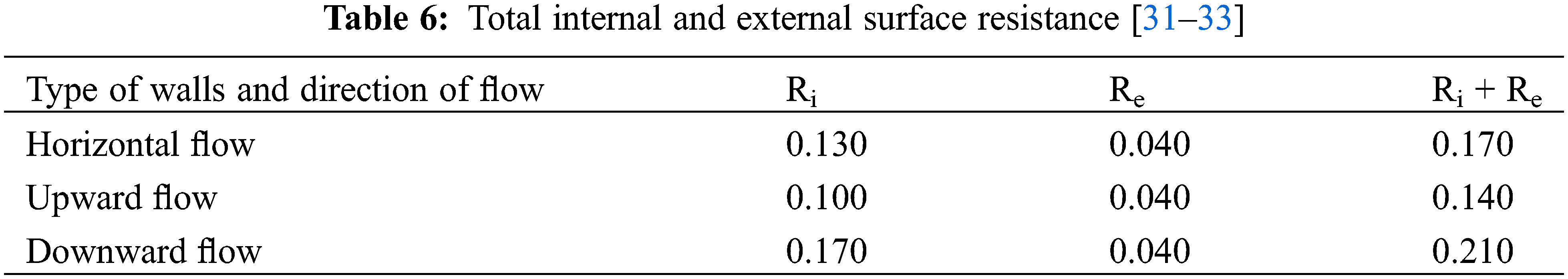
At roof level according to Table 6 the sum of the internal and external surface resistances:
(Ri + Re) roof = (Ri + Re) Upward flow = 0.14 m2.k/W, with (Ri + Re) roof is the total internal and external surface resistance of roof.
At floor level according to Table 6 the sum of the internal and external surface resistances:
(Ri + Re) floor = (Ri + Re) Downward flow = 0.21 m2.k/W, with (Ri + Re) floor is the total internal and external surface resistance of floor.
Likewise, at the level of the south, north, west and east walls according to Table 6 the sum of internal and external surface resistances is the same value:
(Ri + Re) south-wall = (Ri + Re) north-wall = (Ri + Re) west-wall = (Ri + Re) east-wall
= (Ri + Re) Horizontal flow
= 0.17 m2.k/W
With, (Ri + Re) south-wall is the total internal and external surface resistance of the south wall.
(Ri + Re) north-wall is the total internal and external surface resistance of the north wall.
(Ri + Re) west-wall is the total internal and external surface resistance of the west wall.
(Ri + Re) east-wall is the total internal and external surface resistance of the east wall.
3.1 Characterization by Infrared Fourier Transform Spectroscopy (FTIR)
3.1.1 Identification of Wood Fiber Modified by FTIR Spectroscopy
Fig. 4 shows the superposition of FTIR spectra of linseed oil treated wood fiber, pure bio-PCM (coconut oil) and bio-PCM treated wood. The spectrum of wood treated by bio-PCM shows the appearance of new bands around 2931 cm−1 and around 1745 cm−1 which shows that bio-PCM is incorporated and adsorbed into the successfully treated wood fibers (WFT).
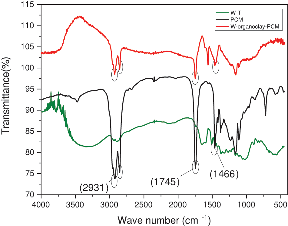
Figure 4: FTIR spectra of wood fiber treated (WFT), coconut oil (bio-PCM) and cement composite (cement + sand + WFT + organoclay + bio-PCM)
3.1.2 Identification of Cement Composite-Coconut Oil (Bio-PCM) by FTIR Spectroscopy
The FTIR spectra of cement composite bio-PCM, pure bio-PCM and cement are shown in Fig. 5. Comparing with the cement spectrum, the bio-PCM cement spectrum reveals new bands: a strip around 2936 cm−1 and a strip assigned to the grouping-CH- which proves the integration of the bio-PCM in the cement. Similarly, the spectrum makes appear a band around 1755 cm−1 attributed to the groups (-C=O). This confirms the existence of bio-PCM in the mortar without any chemical interaction.
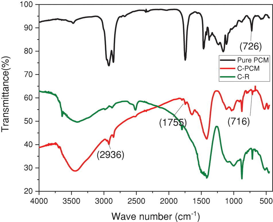
Figure 5: FTIR spectra of cement with sand (C-R), cement with WT with PCM (C-bio-PCM) and bio-PCM
3.1.3 Identification of Organoclay by FTIR Spectroscopy
The FTIR spectrum of the CTAB-modifed clay (Fig. 6) shows two new peaks at 2930 cm−1 and 2857 cm−1, which are due to the symmetric stretching vibration and the asymmetric stretching (hydrophobic) of the (-CH2-) groups of the organic chain of cationic surfactant (CTAB) added to clay. The appearance of a new peak around 1470 cm−1, attributed to the CTAB (-CH2-) group, which shows that the CTAB surfactant is intercalated between the clay layers and pores.
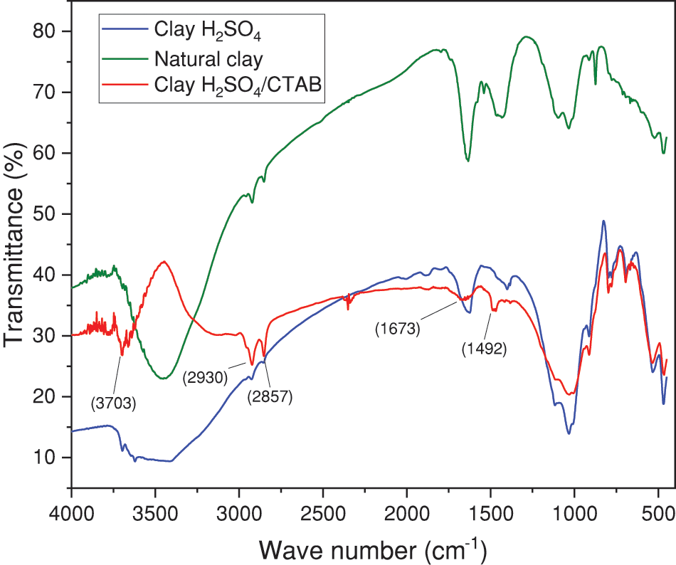
Figure 6: FTIR spectra of pure (natural) clay, clay treated with H2SO4 and clay treated with CTAB (organoclay)
3.2 Characterization by X-Ray Diffraction (XRD)
3.2.1 Identification of Organoclay by XRD
The XRD spectra of pure clay and organophilic clay are displayed in Fig. 7. The XRD pattern of pure clay exhibits typical reflections (2 = 6.8°, 12.1°, 21.02°, 26.64°, and 61.98°). Other peaks in the XRD pattern show evidence of impurities like feldspar (2 = 27.52°) and quartz (2 = 21.02° and 26.88°). Peaks in the diffraction pattern change after the clay has been treated with CTAB. The primary diffraction peak was shifted from 11.92° to 9.54° as a result of the organophilic clay treatment. By separating the reticular planes of the (001) family that pass from d001 = 3.73 A° (2 = 11.92°) at d001 = 4.643 A° (2θ = 9.54°), this change confirms the intercalation of CTAB between the clay layers (Fig. 7).
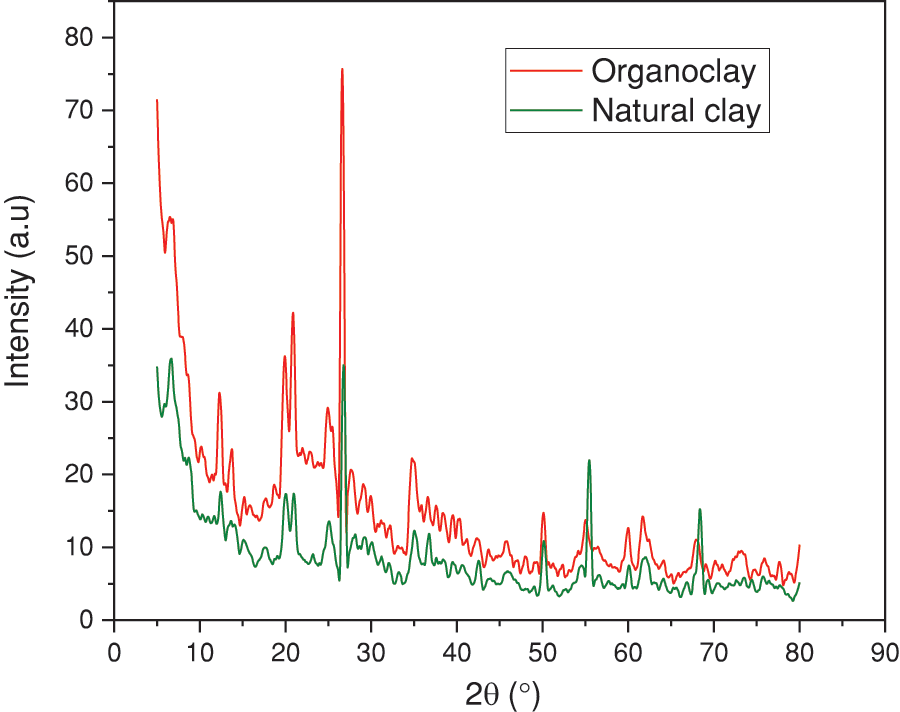
Figure 7: XRD patterns of pure clay and organophilic clay (clay modified with CTAB)
3.2.2 Identification of Wood Fiber Modified with Coconut Oil (Bio-PCM) by XRD
The highly crystalline nature of wood fibers (WF) is an essential parameter which is at the origin of numerous structural properties such as high mechanical resistance, resistance to all conventional organic solvents, resistance to bases and mild acids. It is therefore important, for subsequent applications of modified wood fibers, to check whether the semi-crystalline character is not affected by the chemical treatment of the modification. For this, we established the powder x-ray diffraction spectra of the modified wood fibers. The spectra of the fibers modified by Linseed oil and by Coconut oil (bio-PCM) (Fig. 8) clearly show that they overlap perfectly with those of the original untreated fibers. In addition, the determination of the crystallinity rate by referring to the surface ratio of the parts associated with the crystalline and amorphous phase shows that this rate remains practically unchanged and is around 75%.
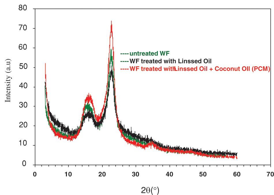
Figure 8: XRD patterns of untreated wood fiber (WF), Wood fiber treated (WFT) with linssed oil and wood fiber treated with (WFT) linssed oil + coconut oil (bio-PCM)
3.3 Thermo-Physical Proprieties of Composite Samples (Porosity and Density)
Composites with WFT often have a lower density than those without WFT. This is explained by the void that developed at the cement matrix and WFT interface. When WFT is added to composite materials at a weight percentage of 2%, the density decreases by 23% (Fig. 9a), indicating that WFT raises the density of cement composites. By using 2 weight percent NFC, the cement composite’s density was decreased. This enhancement demonstrated that the incorporation of WFT leads to a reduction in density and the creation of a composite material with a unified microstructure. Fig. 9b shows the test results on cement paste composites without wood fiber, on composites reinforced with wood fibers and on composites reinforced with wood fibers and an organophilic clay for porosity values.
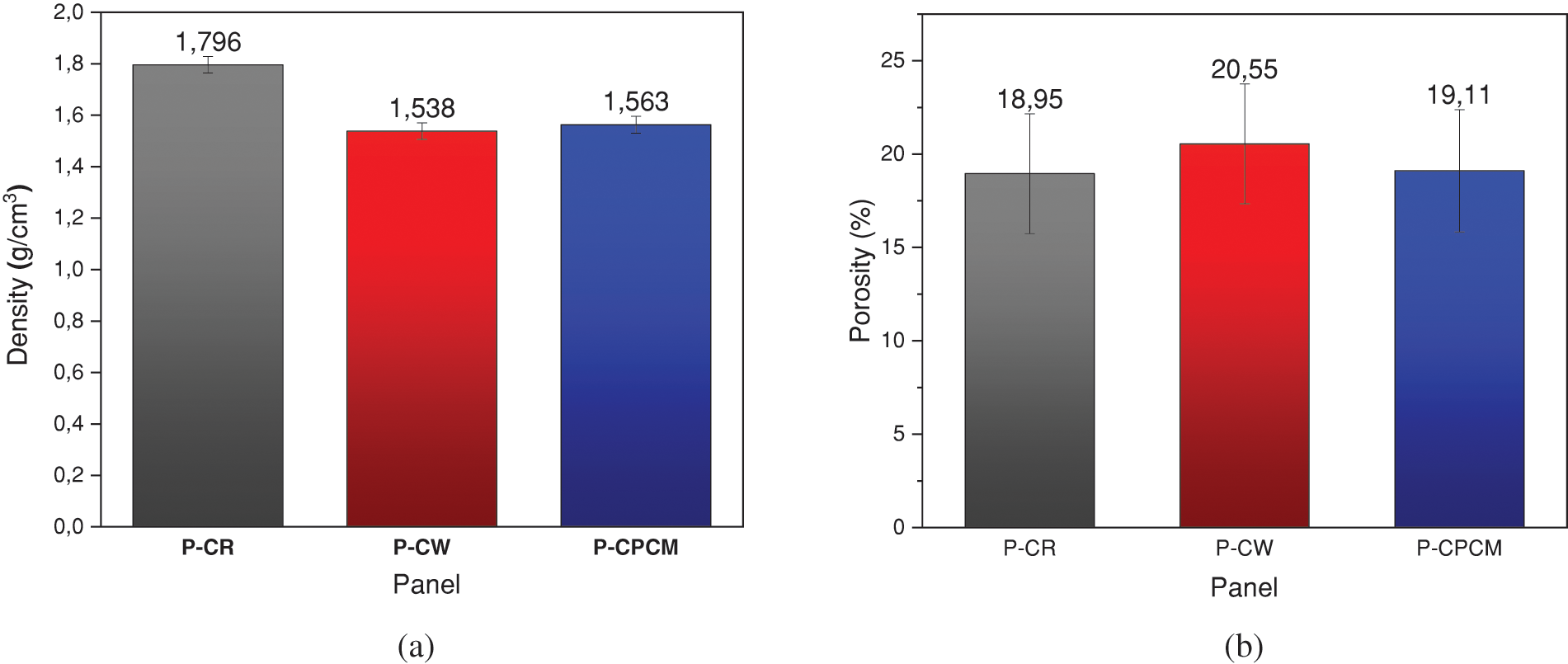
Figure 9: Evolution of density (a) and porosity (b) of the composites developed depending on the content of the panels
When wood fiber is added to composites, porosity decreases by 1.82%, but it is often higher than when it is not. The porosity of these composites demonstrates that wood fiber has a decreasing impact on the porosity of cement paste composites and that for a percentage between 1.5% by weight and 2% by weight of wood fiber, are capable of saturate the surface and reduce pores. The decrease in porosity of the fabricated composite materials is shown in Fig. 9b. The porosity of the composites was in fact reduced by 18.75% when 1% by weight of clay was added, which explains how the organophilic clay helped to fill the spaces between the cement grains. Additionally, for amounts of organophilic clay added to bio-PCM greater than 1 wt%, the agglomeration effect increased the porosity for all samples.
The effect of wood fiber incorporation on this property of composites was examined using the water retention test. The results show, as shown in Fig. 10, that this characteristic increases at a rate that corresponds to the rate of wood fiber incorporation. The water saturation point was reached in all of the different composites after the same amount of time. Generally speaking, the increased water absorption of the composites can be explained by the high capacity of wood fiber for water retention and its continued expanding behavior when in contact with water. Fig. 10 displays the outcomes for the various mixes that were tested, including cement, cement with wood fiber, and cement with wood fiber treated with bio-PCM (P-CW). According to this graph, the maximum water absorption starts to be attained after 25 min for panel with cement and 0% wood fiber (P-CR). As the amount of time increases until saturation, the rate of water absorption then decreases.
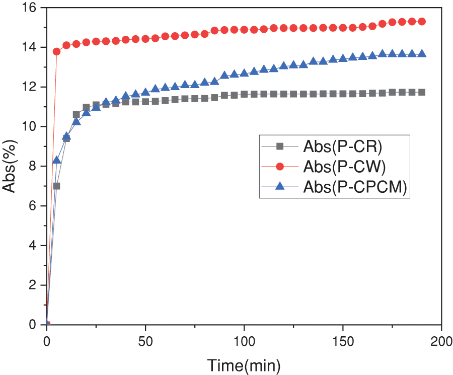
Figure 10: Effect of wood fiber treatment on the water absorbances of different composite panels developed
Additionally, it was found that the composite reinforced with wood fiber (P-CW) absorbed water for a shorter period of time (75 min) than the composite treated with bio-PCM (P-CPCM) for the wood fiber (150 min). Since the composite contains more and more wood fiber that has been treated with bio-PCM, it becomes increasingly hydrophobic, which may be partially due to a higher hydrophobicity.
To examine the sample surfaces’ appearance and the impact of various wood fiber treatments on water absorbance, we used contact angle measurement. In fact, measurements of the contact angles of a drop of water on samples were made using a CCD camera, which can capture the appearance of a calibrated drop of water at a speed of 30 images per second. After that, it is possible to analyze the drop’s contour and precisely calculate the contact angle with the flat surface thanks to sophisticated image processing software. Fig. 11 displays the evolution of the contact angles for the various samples.
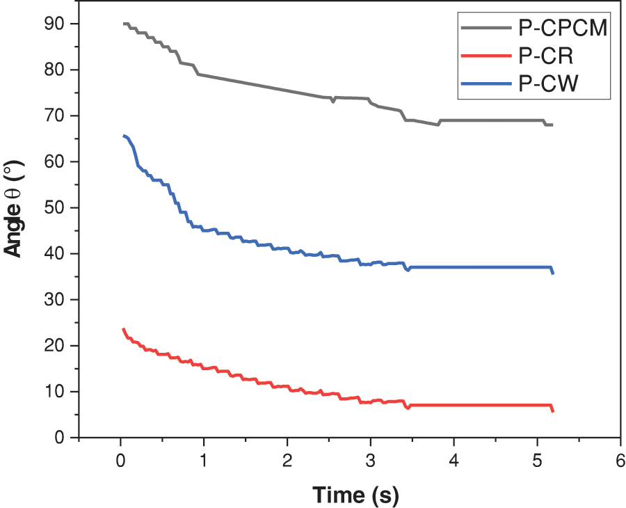
Figure 11: Evolution of the surface of the pannel material from the hydophilic state to the hydrophobic state
According to the analysis, wood fibers treated with bio-PCM (P-CPCM) have their surface properties change from a very noticeable hydrophilic state to a hydrophobic state.
We can clearly see a difference in the variation of these angles by examining the results of the analysis of the evolution of the contact angles over time. In fact, the contact angle increases when coconut oil is present in the panels (P-CPCM), suggesting that the presence of alkyl chains, which will cover the surface while adopting a configuration perpendicular to the surface, is related to the evolution of the surface’s character.
The stability of a bio-based phase change material (bio-PCM) in a composite material is something we want to emphasize in this study because it is crucial for applications that aim to improve building thermal insulation or thermal energy storage. In order to accomplish this goal, studies on sealing and leakage tests of bio-PCMs incorporated in various composite materials were conducted. The samples were prepared as pellets in the shape of cylinders, laid out on filter paper, and kept in an oven at 30°C for two hours (Fig. 12a). We have compiled the leak test results in Fig. 7b. These findings led to the following strategies:
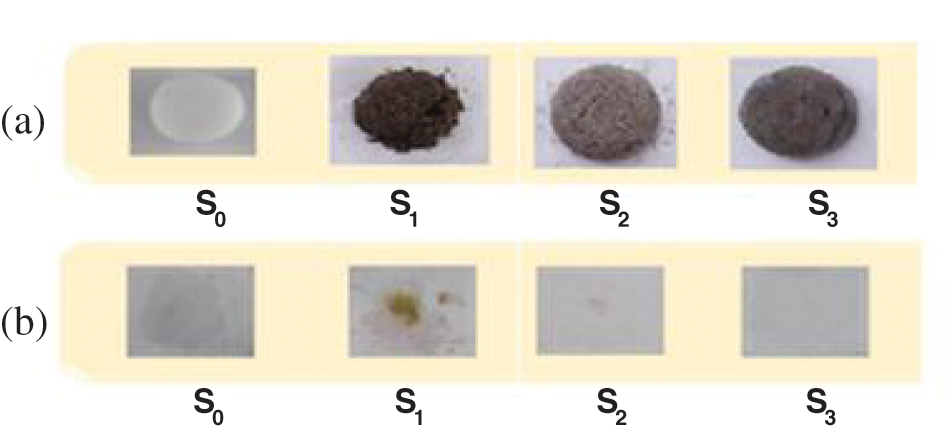
Figure 12: Leakage test of different composite materials: (a) before heating and (b) after heating at temperature 30°C
-The pellet of S0 (100 percent bio-PCM plus 0 percent of cement, sand, organic clay, and wood fiber) demonstrates that the PCM is melted into liquid form.
-A composite material leak exists in the S1 pellet (Cement + Sand + 17.5% bio-PCM).
-The S2 pellet, which contained cement, sand, wood fiber, and 17.5% bio-PCM, demonstrated that a significant portion of the bio-PCM was retained by the wood fibers, leaving a small stain on the filter paper.
-The S3 pellet, which consisted of cement, sand, wood fiber, organic clay, and 17.5% bio-PCM, demonstrated that bio-PCM becomes more stable in the matrix of a composite with no leakage (Fig. 12b). As a result of the interaction between the wood fibers and the organophilic clay layers treated with the CTAB surfactant, the results demonstrate that the bio-PCM leakage problem is improved by the stabilization of the shape of the S3 composite material. The created composite material displayed excellent thermal and structural stability.
3.7 Analysis of Thermal Properties
3.7.1 Thermal Characterization by Conductivity
The evolution of the thermal conductivity and thermal resistance of the different panels developed according to the different reinforcements is shown in the Fig. 13. From these curves, it was found that the addition of 2% sawdust (untreated wood fiber) to the P-CW plate causes a decrease in thermal conductivity from 0.875 to 0.67 W/m.k with a 23.42% increase in thermal conductivity (Fig. 13a) compared to the reference plates (P-CR), this result is attributed to the insulating effect of the wood fiber since its thermal resistance is low with a value between 0.02 and 0.026 W/m.k which resulted in an improvement of 30% in thermal resistance (Fig. 13b) compared to that of cement and sand.
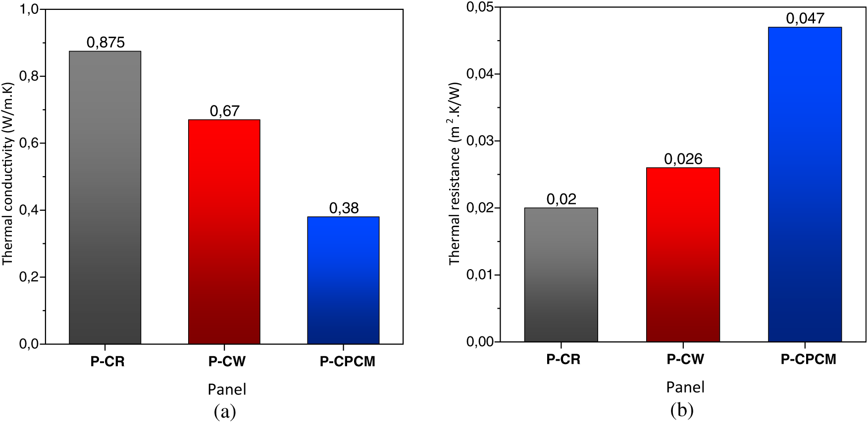
Figure 13: Thermal conductivity (a) and thermal resistance (b) of different square panel
On the other hand, we can say that the presence of a thin layer of 0.8 cm containing PCM from bio-sourced wood within the P-plate CPCM promotes the strong reduction in thermal conductivity of the order of 0.875 to 0.38 W/m.k which means a reduction in thermal conductivity to approximately 56.57% compared to the reference plates (P-CR). This result is closely linked to the low thermal conductivity of these reinforcements (treated wood fiber, clay, coconut oil (bio-PCM)) compared to that of cement and to the position of the composite bio-PCM layer. To summarize, it was confirmed that the developed P-CPCM sandwich insert has optimal performance to exploit them on the interior walls of the building.
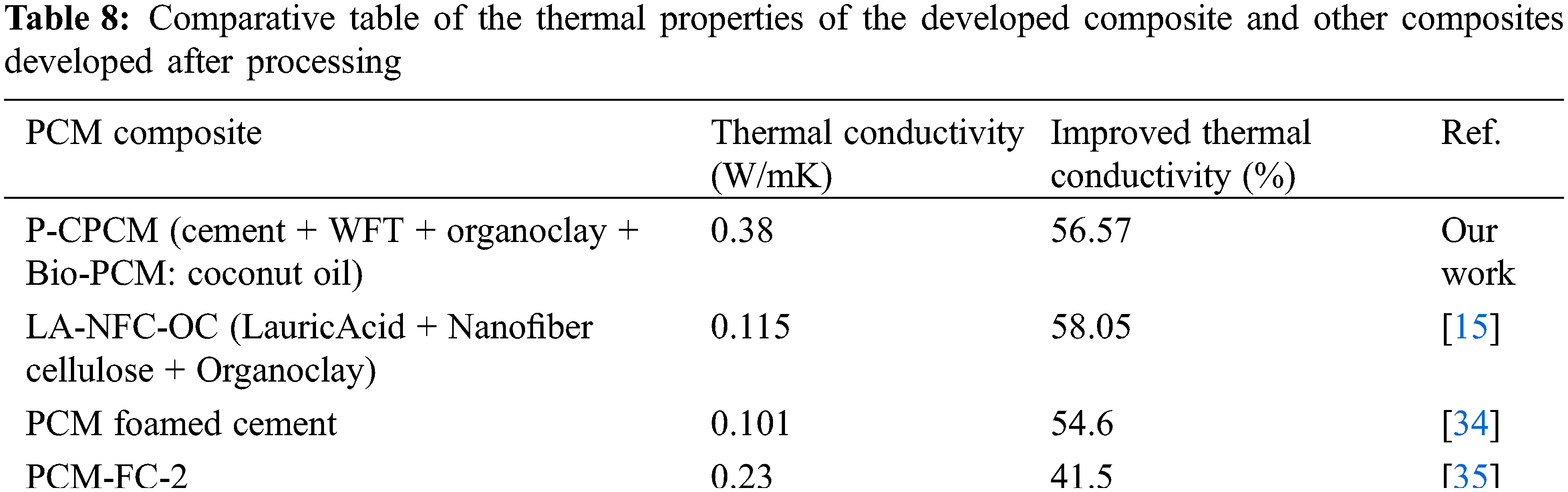
We made a comparison of our results with those found in the literature relating to thermal characteristics of PCM similar to our work [15,22]. This decrease can be the consequence of introducing insufficient WFT to encourage the creation of a standardized framework. In addition, the porosity, water content, temperature, and constituent constituents of a substance all influence its thermal conductivity. Consequently, the WFT surface showed the presence of the new pores causing a decrease in the adhesion between the fibers and the cement matrix.
3.7.2 Analysis of Thermal Properties by DSC
Differential scanning calorimetry was carried out to determine the melting temperature, solidification temperature, enthalpy of pure bio-PCM and composite bio-PCM to test their stability and encapsulation degree. In this context, the figure shows the DSC curve of coconut oil (pure bio-PCM) with a heating (or cooling) rate of 5°C/min, this graph shows on the one hand an endothermic signal observed at the phase heating and on the other hand an exothermic signal corresponds to the cooling of the bio-PCM (Fig. 14). The Fig. 14a shows a peak of the endothermic signal reflecting the solid-liquid phase change of coconut oil for a melting temperature of around 23.54°C with an enthalpy of around 56.38 J/g. In contrast, the peak of the exothermic signal shows the liquid-solid phase change of this bio-PCM and presents a solidification temperature of 3.34°C and an enthalpy of −49.32 J/g. We note that the melting temperature of the walnut oil is close to the thermal comfort temperature in summer and winter, which proves the effect of integration of wood fibers treated with bio-PCM in construction materials and more precisely cementitious materials as a thermal storage system or for thermal insulation (Fig. 14a).
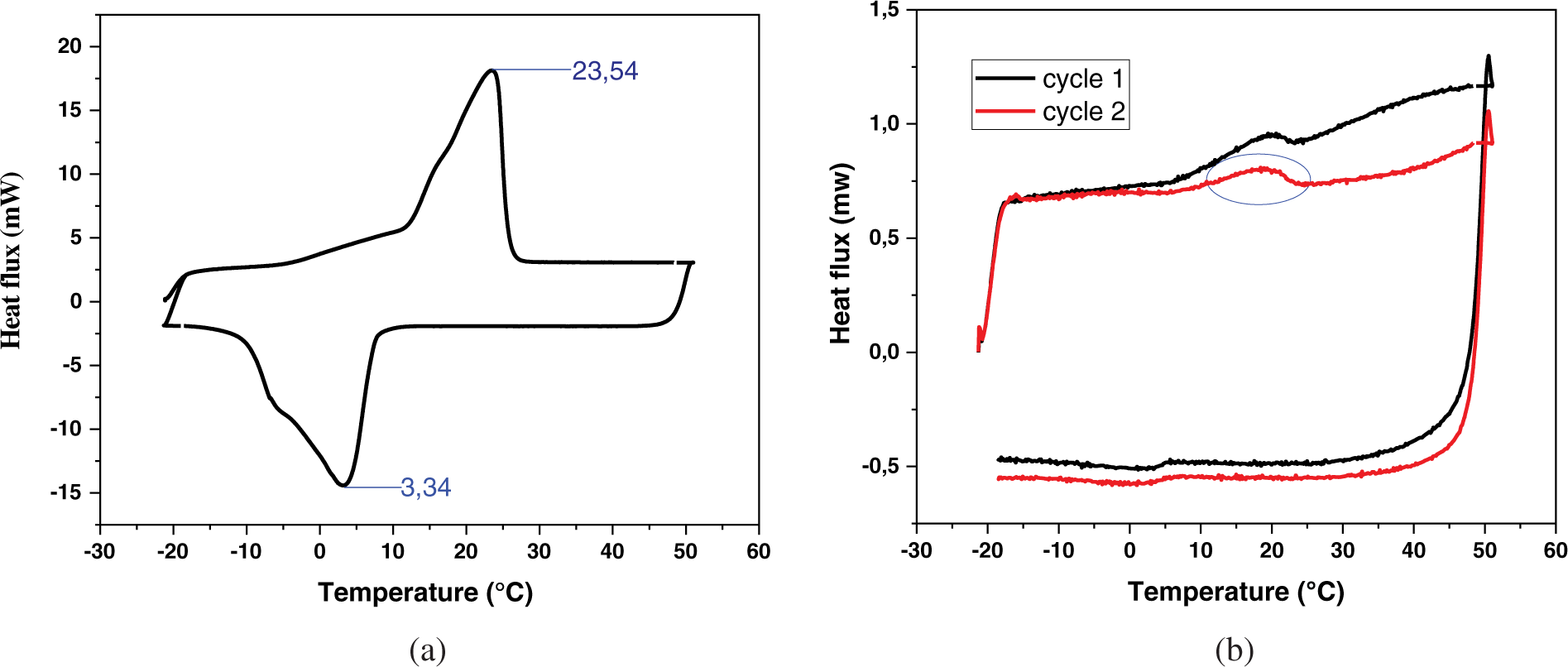
Figure 14: DSC curves of bio-PCM (a) and bio-PCM-composite (b)
However, the prepared sample has good thermal energy storage performance (large latent heat of fusion and solidification) and no bio-PCM leakage is related. This makes these composites good candidates for energy storage in buildings. The quantity of bio-PCM trapped in the organophilic clay by the impregnation method was sufficient to confirm that this material has an insulation and thermal storage aspect.
The possibility of using bio-PCMs in engineering applications is linked to their ability to store/release thermal energy within a useful temperature range. Therefore, the study of thermal properties of the prepared samples plays a major role in the present study. The DSC analysis presents the phase transition temperatures and latent heat for two panel melting/solidification cycles developed as shown in Fig. 14b. The DSC thermograms respectively present the endothermic and exothermic curves with reproducibility and good shape stability.
3.8.1 Application of the Various Panels Developed on the Internal Walls of a Room Linked to the Solar System
The room connected to the solar heating system is an experimental prototype made of a Plexiglas envelope. For our work, we consider that the room is made up of exterior Plexiglas walls and interior cement walls constituting the reference room. In this part, we study the temperature field through the different panels developed. Through a comparison between the two doors, the heat loss values of each category were determined, knowing that the experimental tests retained in meteorological conditions are close at the time of the test in the reference room. In order to study the thermal insulation effect of the different panels developed, we started by adding P-CR reference cementitious panels to the interior walls of the Plexiglas envelope with a thermal conductivity of 0.87 W/m.k and a thickness of 1.8 cm, the variation of the internal temperature of the reference room and the outside air temperature are shown in the Fig. 15a.
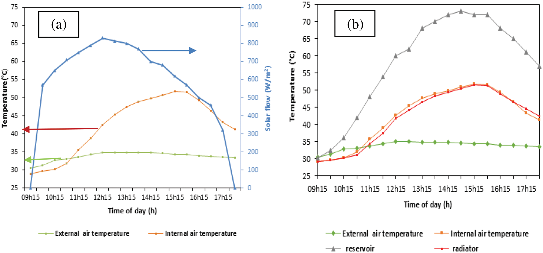
Figure 15: Indoor and outdoor temperature evolution through the reference chamber with solar flux (a) and with radiator and tank temperature (b)
Indeed, this experiment was carried out on September 01, 2023 from 09h15 to 17h15 in a species located between two buildings such that the solarimeter measures zero solar radiation from 09h15 to 09h45 and at 17h15 and maximum solar radiation reaches 830 W/m2. Additionally, the temperature field measurement is recorded every 30 min.
At the start of the experiment, the solar heating system and the room are not exposed to solar radiation, which explains the decrease in the temperature in the room compared to the outside temperature. From 10h15, the measured solar flux begins to increase, which encourages an increase in the temperature inside the room. During the experiment, a maximum interior temperature reached 51.8°C providing thermal comfort within the room for an exterior temperature of 34.4°C, which gives a phase shift of 17.4°C. Likewise, the temperature of the tank and the maximum temperature of the radiator are respectively 72°C and 60.5°C (Fig. 15b), which corresponds to the duration of sunshine and the value of solar radiation. From the curves in Fig. 15b, we observe a superposition between the radiator and the internal air temperature which shows that the radiator transfers its heat to the interior atmosphere of the room by natural convection.
Fig. 16 shows that the temperature at the ceiling level is the highest temperature and this can be explained by the position of this face which receives the greatest solar flux compared to the interior walls. On the other hand, the floor panel has the lowest temperature due to its position away from solar radiation.
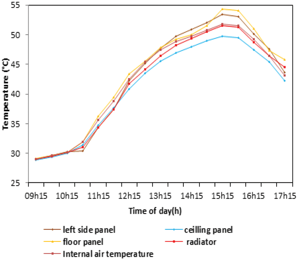
Figure 16: Evolution of the temperature profile to the interior atmosphere and the interior walls of the reference room
3.8.2 Energy Performance Study of Wood Cement Walls
This experimental test is carried out on September 21, 2023 from 09h15 to 17h15 in note that the solarimeter measures a zero solar radiation from 09h15 to 10h15 and from 16h45 to 17h15 and reveals a maximum solar radiation reaches 730 W/m2.
To improve the thermal insulation at the local level, we placed elaborate P-CW panels on the internal walls of thermal conductivity chamber of 0.67 W/m.k and thickness 1.8 cm. The evolution of the interior temperature of the P-CW panel room and the external air temperature is shown in Fig. 17.
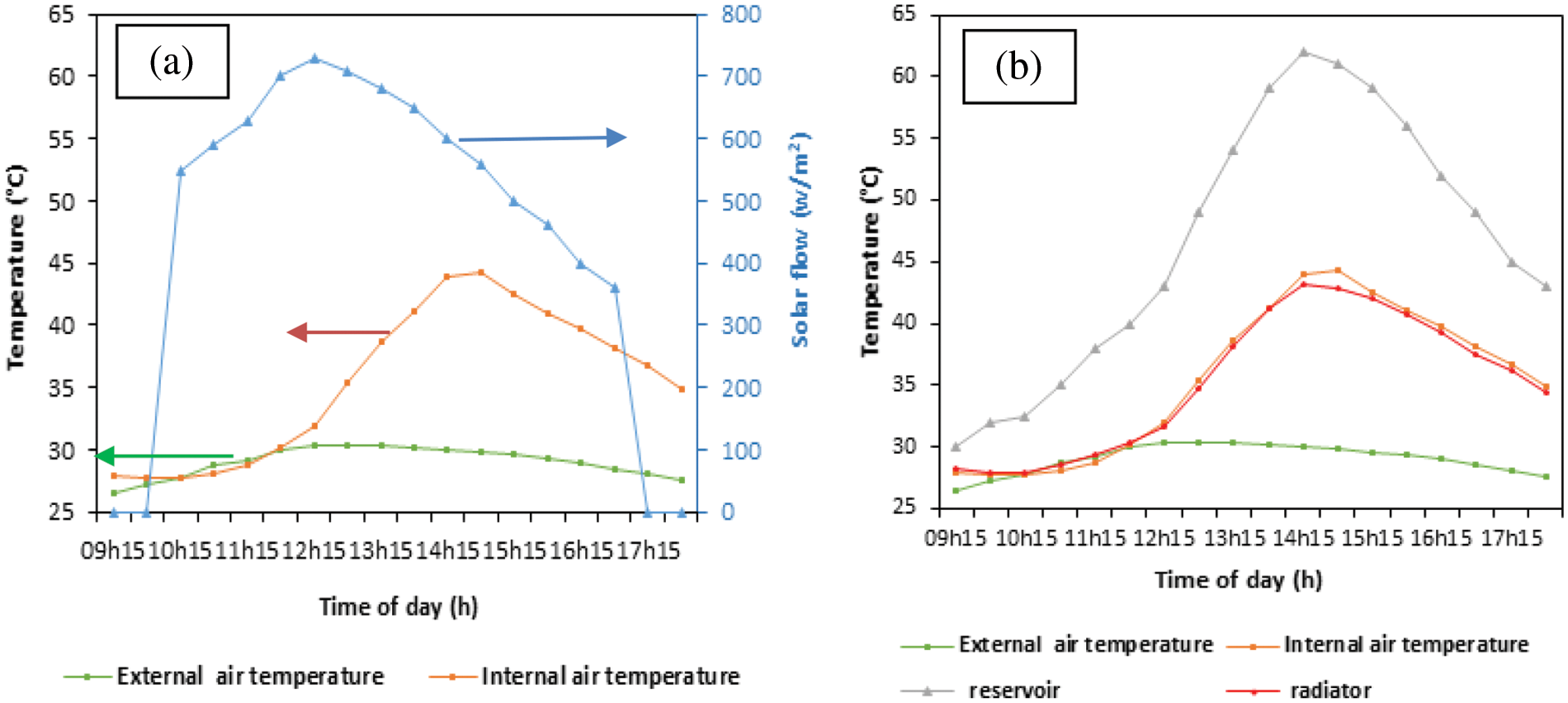
Figure 17: Outside and interior temperature evolution through P-CB panels with solar flux (a) and with radiator and tank temperature (b)
According to curve of Fig. 17a, and at the beginning of the experiment, we notice a small difference in temperature between the indoor and outdoor atmosphere due to the absence of solar flux. Following the appearance of incident solar flux, the indoor and outdoor temperature field begins to increase, giving rise to a phase shift of 14.4°C.
During this experimental test and through the P-CW panels, it is observed that the maximum indoor temperature reaches 44.3°C in front of a maximum outdoor temperature of 30.4°C otherwise, the radiator and tank temperatures are found to reach 43.1°C and 62°C successively. Thus, according to Fig. 17a, there is a similarity between the temperature of indoor environment and that of the radiator. This superposition results in convection heat transfer. Indeed, according to Fig. 18, we find that the temperature field through the various internal walls P-CW approaches the reference one. From this superposition of temperature profile, it can be concluded that the P-CW panels oppose the heat transfers between the internal atmosphere and the external environment which favors the improvement of the thermal insulation at the local level through the P-CW panels.
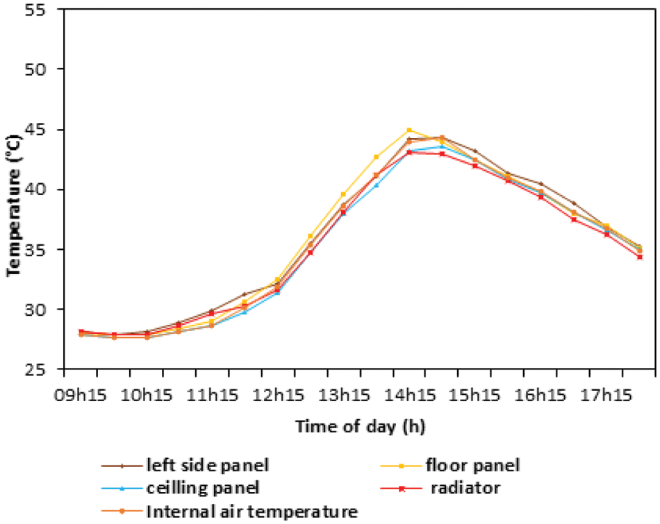
Figure 18: Evolution of the temperature profile to the interior atmosphere and the interior walls of P-CW panels
3.8.3 Energy Performance Study of P-CPCM Panels Walls
We finalize our experimental tests by putting the P-CPCM panels developed on the internal walls of the local, in fact this study was carried out on October 4, 2023 from 09h15 to 20h45 in note although the Solarimeter records a zero solar radiation from 09h15 to 11h15 and 15 to 20h45 and maximum solar radiation reaches 670 W/m2.
From Fig. 19a, for four hours of sunlight and a maximum radiation of 690 W/m2 the maximum indoor and outdoor temperature through the bio-PCM panels successively reaches 43.9°C and 29.1°C which gives rise to a phase shift of 14.8°C while the temperature at the tank level and radiator do not successively exceed 63°C and 42.6°C, compared to the reference and wood panels, which have 7.5 and 6.5 h of sunshine respectively (Figs. 15a and 17b), P-CPCM cement panels are the most insulating inner walls. Thus, these cementitious phase change material panels have a phase shift of 14.8°C.
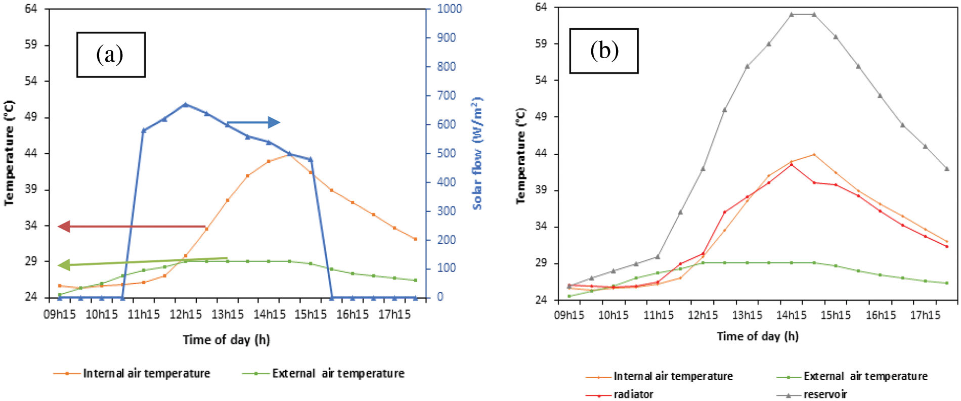
Figure 19: Outside and interior temperature evolution through P-CPCM panels with solar flux (a) and with radiator and tank temperature (b)
According to Fig. 19a and at the beginning of the experiment, it is observed that the radiator temperature is higher than the temperature of the internal atmosphere this shift begins to reverse at 12h15 and when the value of solar radiation exceeds its maximum (690 W/m2). This can be explained by the decrease of solar flux which promotes the proper functioning of solar heating system and subsequently ensures the rise of radiator temperature. The energy performance study of P-CPCM panels in the absence of solar radiation is shown in Fig. 20, knowing that this test was carried out from 15h45 to 20h45.
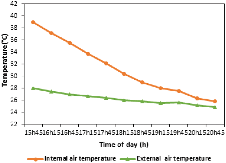
Figure 20: The evolution of interior and outside temperatures through P-CPCM panels without the presence of solar radiation
According to Fig. 20, for five hours of absence of sunlight exposed to the solar heating system, we observe that the temperature in the interior environment remains high compared to that of the exterior. Thus, the interior temperature profile begins to decrease to reach values close to those of the exterior. In fact, this approach is confused with the summer thermal comfort temperature (between 24°C and 26°C), in this case around 20h45. the night becomes cooler thanks to the heat accumulated by the phase change cement panels P-CPCM.
3.9 Comparison of Local Heat Loss through the Different Panels Developed
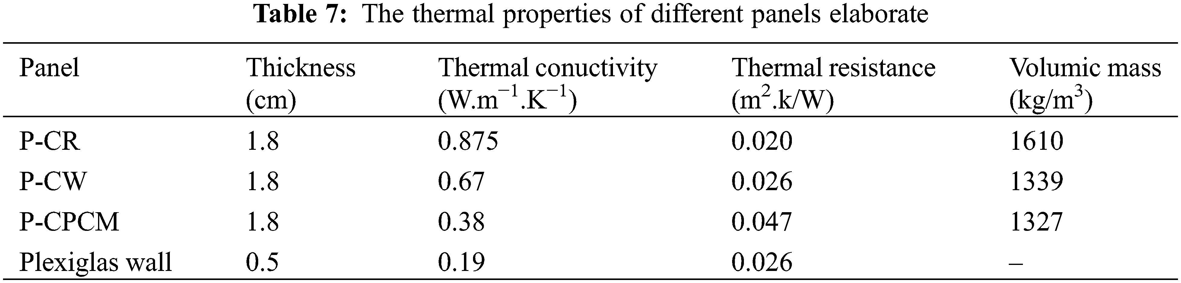
In this part we presented the heat losses for each category of the panels produced. We began our study by calculating the thermal resistance of the exterior plexiglass panel and different contributed panels, thus the thermal properties of these materials are illustrated in Table 7.
We made a comparison of our results with those found in the literature relating to thermal characteristics of PCM similar to our work (Table 8).
Then we determined the surface heat losses of the envelope through the various panels developed thus, Tables 9–11 present these values.
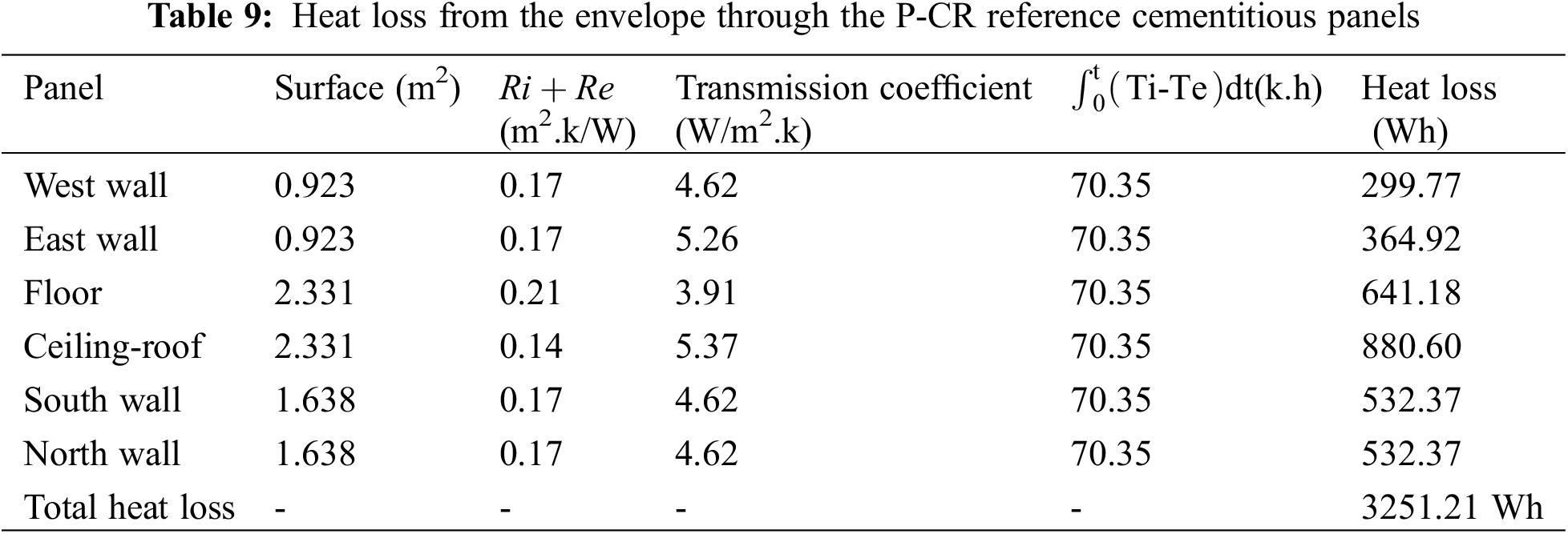
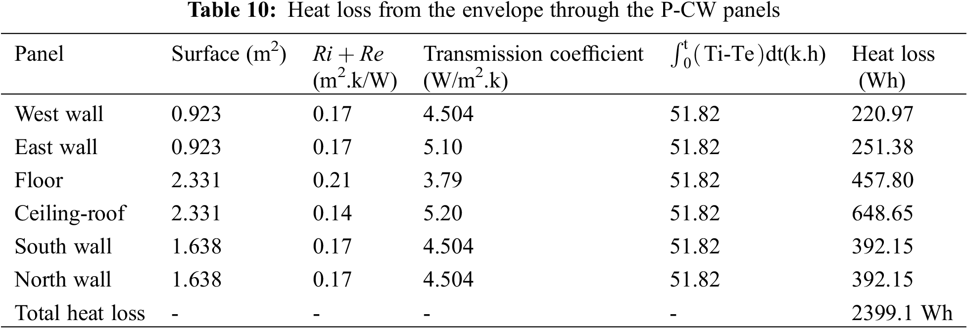
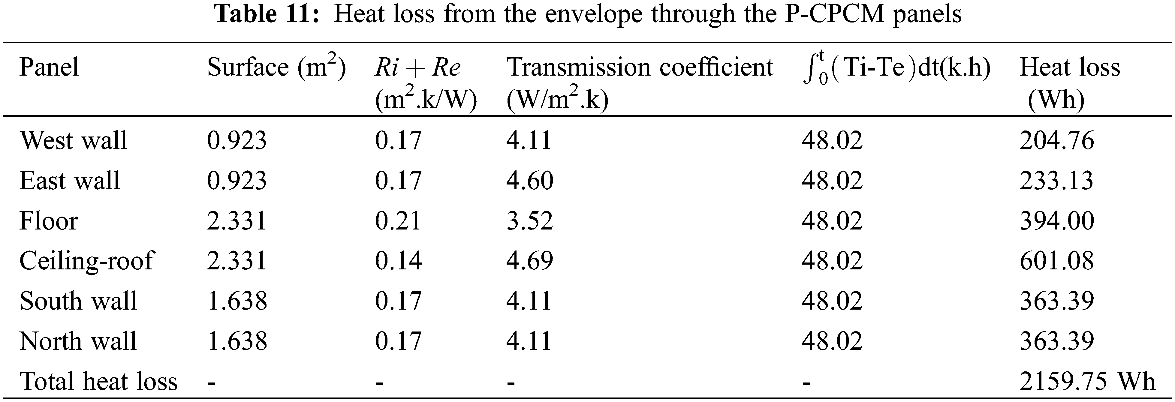
According to our study, cementitious panels with phase change (P-CPCM) have the lowest thermal loss value compared to that of reference (P-CR) and wood (P-CW) due to their low thermal conductivity. At the local level, it can be concluded that the incorporation of a composite bio-PCM layer in the middle of a cementitious panel improves 33.57% of their thermal loss. In fact, the strong reduction of heat loss through the envelope containing the P-CPCM panels reflecting their high thermal inertia by transmission. It can be concluded that P-CPCM composite panels with low thermal diffusivity ensure the reduction in heating need.
In this study, cementitious panels of cement/wood fiber/bio-PCM/organic clay boards were prepared through a two-step intercalation process. The first step was the ion exchange intercalation of organophilic clays with the surfactant CTAB, followed by the production of a secondary hydrophobic attractive force for the coconut oil fat adsorbed on the wood fibers and trapped between the layers of organophilic clay. Clay spacing shifted correspondingly, extending to organic clays after CTAB intercalation and eventually to higher spacing.
The cement/wood fiber/grease, coconut oil (bio-PCM)/organophilic clay boards were suitable for a phase change material that remained solid without liquid leakage even when heated above the melting point of coconut oil fat.
DSC study revealed that organophilic clay increased the thermal stability of coconut oil fat (bio-PCM) substantially. The elaborate panels are regarded as a novel energy storage material, or PCM, capable of absorbing and releasing heat in response to variations in ambient temperature.
The obtained latent heat capacity represents a very large thermal storage capability in building envelopes for a melting temperature of approximately 23.54°C and an enthalpy of approximately 56.38 J/g. This bio-PCM, on the other hand, has a solidification temperature of 3.34°C and an enthalpy of −49.32 J/g for the liquid-solid phase shift.
Because it has high thermal stability qualities, it can maintain up to 98.25% by mass of coconut oil fat (bio-PCM) without any leakage occurrence, leading to a reduction of around 56.57% in thermal conductivity and an increase of 135% in thermal resistance.
Composite panels containing renewable materials wood fibers and organophilic clay had lower density than those that did not. This could be explained by the void that formed at the junction of the wood fiber and the cement matrix. In fact, these composite materials comprising 2% by weight wood fibers resulted in a 23% reduction in panel density.
Based on the temperature field study, which was carried out at the level of the glass solar collector and at the local level through the various panels developed, the P-CPCM panels presented a potential for efficiency in thermal insulation even in adverse weather circumstances (poor solar radiation).
Furthermore, the heat loss study for each category of panels developed revealed that P-CPCM panels reduced heat losses by 33.57% compared to P-CR reference panels, demonstrating their strong thermal inertia at the building level and ability to reduce energy consumption (for our study of heating needs).
Acknowledgement: Authors are grateful to the Laboratory of Energy and Materials (LABEM), University of Sousse and Laboratoire Sciences des Matériaux et Environnement (LMSE), University of Sfax, Tunisia for the financial support of this work.
Funding Statement: The authors received no specific funding for this study.
Author Contributions: All authors contributed to the study conception and design. Material preparation, data collection, and analysis were performed by Yosr Laatiri and Fadhel Aloulou. The first draft of the manuscript was written by Fadhel Aloulou. Then, it was revised by Habib Sammouda and Fadhel Aloulou commented on previous versions of the manuscript. All authors read and approved the final manuscript.
Availability of Data and Materials: Data available on request from the authors.
Conflicts of Interest: The authors declare that they have no conflicts of interest to report regarding the present study.
References
1. Zhou D, Zhao CY, Tian Y. Review on thermal energy storage with phase change materials (PCMs) in building applications. Appl Energy J. 2012;92:593–605. doi:10.1016/j.apenergy.2011.08.025. [Google Scholar] [CrossRef]
2. Jouhara H, Żabnieńska-Góra A, Khordehgah N, Ahmed D, Lipinski T. Latent thermal energy storage technologies and applications. A review. Int J Thermofluids. 2020;5–6:100039. doi:10.1016/j.ijft.2020.100039. [Google Scholar] [CrossRef]
3. Guelpa E, Verda V. Thermal energy storage in district heating and cooling systems: a review. 2019;252:113474. doi:10.1016/j.apenergy.2019.113474. [Google Scholar] [CrossRef]
4. Rathore PSK, Shukla SK. Potential of macroencapsulated pcm for thermal energy storage in buildings: a comprehensive review. Constr Build Mater J. 2019;225:723–44. doi:10.1016/j.conbuildmat.2019.07.221. [Google Scholar] [CrossRef]
5. Rathore PSK, Shukla SK, Gupta NK. Potential of microencapsulated PCM for energy savings in buildings: a critical review. Sustain Cities Soc. 2020;53:101884. doi:10.1016/j.scs.2019.101884. [Google Scholar] [CrossRef]
6. Dhaidan NS, Khodadadi JM. Melting and convection of phase change materials in different shape containers: a review. Renew Sustain Energ Rev. 2015;43:449–77. doi:10.1016/j.rser.2014.11.017. [Google Scholar] [CrossRef]
7. Nejman Alicja, Gromadzińska E, Kamińska I, Cieślak M. Assessment of thermal performance of textile materials modified with PCM microcapsules using combination of DSC and infrared thermography methods. Mol. 2020;25(1):122–35. doi:10.3390/molecules25010122 [Google Scholar] [PubMed] [CrossRef]
8. Akeiber H, Neat P, Abd Majid MZ, Wahid MA, Jomehzadeh F, Famileh IZ, et al. A review on phase change material (PCM) for sustainable passive cooling in building envelopes. Renew Sustain Energ Rev. 2016;60:1470–97. doi:10.1016/j.rser.2016.03.036. [Google Scholar] [CrossRef]
9. Wang L, Meng D. Fatty acid eutectic/polymethyl methacrylate composite as form-stable phase change material for thermal energy storage. Appl Energy J. 2010;87(8):2660–5. doi:10.1016/j.apenergy.2010.01.010. [Google Scholar] [CrossRef]
10. Cai Y, Hu Y, Song L, Lu H, Chen Z, Fan W. Preparation and characterizations of HDPE-EVA alloy/OMT nanocomposites/paraffin compounds as a shape stabilized phase change thermal energy storage material. Thermochim Acta. 2006;451:44–51. doi:10.1016/j.tca.2006.08.015. [Google Scholar] [CrossRef]
11. Molefi JA, Luyt AS, Krupa I. Comparison of LDPE, LLDPE and HDPE as matrices for phase change materials based on a soft Fischer-Tropsch paraffin wax. Thermochim Acta. 2010;500(1):88–92. doi:10.1016/j.tca.2010.01.002. [Google Scholar] [CrossRef]
12. Xiao M, Feng B, Gong K. Preparation and performance of shape stabilized phase change thermal storage materials with high thermal conductivity. Energy Convers Manag. 2002;43(1):103–8. doi:10.1016/S0196-8904(01)00010-3. [Google Scholar] [CrossRef]
13. Alkam C, Kaya K, Sari A. Preparation, thermal properties and thermal reliability of form-stable paraffin/polypropylene composite for thermal energy storage. J Polym Environ. 2009;17(4):254–8. doi:10.1007/s10924-009-0146-7. [Google Scholar] [CrossRef]
14. Putra N, Prawiro E, Amin M. Thermal properties of beeswax/CuO nano phase-change material used for thermal energy storage. Int J Technol. 2016;7(2):244–53. doi:10.14716/ijtech.v7i2.2976. [Google Scholar] [CrossRef]
15. Zormati S, Mhiri H, Aloulou F, Sammoda H. Synthesis and characterization of organoclay and cellulose nanofibers modified with lauric acid eutectic as new phase change material (PCM) used in buildings for thermal energy storage. J Therm Anal Calorim. 2023;148(10):3955–64. doi:10.1007/s10973-023-12025-3. [Google Scholar] [CrossRef]
16. Leite da Cunha SR, Barroso de Aguiar JL. Phase change materials and energy efficiency of buildings: a review of knowledge. J Energy Storage. 2020;27:101083. doi:10.1016/j.est.101083. [Google Scholar] [CrossRef]
17. Lin W, Ma Z, Ren H, Liu J, Li K. Solar thermal energy storage using paraffins as phase change materials for air conditioning in the built environment. In: Paraffin. London, UK: IntechOpen; 2020. p. 1–15. doi:10.5772/intechopen.86025. [Google Scholar] [CrossRef]
18. Inaba H, Tu P. Evaluation of thermophysical characteristics on shape-stabilized paraffin as a solid-liquid phase change material. Heat Mass Transf. 1997;32(4):307–12. doi:10.1007/s002310050126. [Google Scholar] [CrossRef]
19. Trigui A, Karkri M, Boudaya C, Candau Y, Ibos L, Fois M. Experimental investigation of a composite phase change material: thermal-energy storage and release. J Compos Mater. 2012;48(1):49–62. doi:10.1177/0021998312468185. [Google Scholar] [CrossRef]
20. Wang W, Yang X, Fang Y, Ding J. Preparation and performance of form-stable polyethylene glycol/silicon dioxide composites as solid-liquid phase change materials. Appl Energy J. 2009;86(2):170–4. doi:10.1016/j.apenergy.2007.12.003. [Google Scholar] [CrossRef]
21. Zormati S, Mhiri H, Aloulou F, Sammouda H. Treatments of nanofiber cellulose biomass for cementitious building materials. Euro-Med J Environ Integr. 2023;8(1):15–28. doi:10.1007/s41207-023-00350-w. [Google Scholar] [CrossRef]
22. Zormati S, Aloulou F, Sammouda H. Effects of cationic surfactant on fresh and hardened properties of cement-based mortar. J Renew Mater. 2023;11(5):2345–65. doi:10.32604/jrm.2023.026170 [Google Scholar] [CrossRef]
23. Velazquez-Torres N, Martinez H, Porcayo-Calderon J, Vazquez-Velez E, Gonzalez-Rodriguez JG, Martinez-Gomez L. Use of an amide-type corrosion inhibitor synthesized from the coffee bagasse oil on the corrosion of Cu in NaCl. Green Chem Lett Rev. 2018;11(1):1–11. doi:10.1080/17518253.2017.1404645. [Google Scholar] [CrossRef]
24. Aloulou F, Alila S, Sammouda H. Stabilization and evaluation of modified nanofiber flour wood on the properties of cement-baszd mortar. J Renew Mater. 2019;7(8):763–74. doi:10.32604/jrm.2019.04071 [Google Scholar] [CrossRef]
25. Li G. Energy and exergy performance assessments for latent heat thermal energy storage systems. Renew Sustain Energ Rev. 2015;51:926–54. doi:10.1016/j.rser.2015.06.052. [Google Scholar] [CrossRef]
26. Feng L, Zheng J, Yang H, Guo Y, Li W, Li X. Preparation and characterization of polyethylene glycol/active carbon composites as shape-stabilized phase change materials. Sol Energy Mater Sol Cells J. 2011;95(2):644–50. doi:10.1016/j.solmat.2010.09.033. [Google Scholar] [CrossRef]
27. Hosseini ES, Saoirse, Devin S, Ganguly P, Dahiya R. Biodegradable materials for sustainable health monitoring devices. ACS Appl Mater J. 2021;4(1):163–94. doi:10.1021/acsabm.0c01139 [Google Scholar] [PubMed] [CrossRef]
28. Azeta O, Ayeni AO, Agboola O, Elehinafe FB. review on the sustainable energy generation from the pyrolysis of coconut biomass. Sci African J. 2021;13:909–24. doi:10.1016/j.sciaf.2021.e00909. [Google Scholar] [CrossRef]
29. Nazari M, Jebrane M, Terziev N. Multicomponent bio-based fatty acids system as phase change material for low temperature energy storage. J Energy Storage. 2021;39:102645. doi:10.1016/j.est.2021.102645. [Google Scholar] [CrossRef]
30. Qi X, Huang Y, Li X, Hu Z, Ying J, Li D. Mechanical properties of sea water sea sand coral concrete modified with different cement and fiber types. J Renew Mater. 2020;8(8):915–37. doi:10.32604/jrm.2020.010991 [Google Scholar] [CrossRef]
31. Franco JT. How to calculate the thermal transmittance (U-Value) in the envelope of a building; 2018. Available from: https://www.archdaily.com/898843/how-to-calculate-the-thermal-transmittance-u-value-in-the-envelope-of-a-building. [Accessed 2023]. [Google Scholar]
32. Anderson B, Kosmina L. Conventions for U-value calculations. UK: BRE Electronic Publications. 2019. [Google Scholar]
33. ISO EN7010. The National Standards Authority of Ireland (NSAI) produces the following categories of formal documents. Oxford: Distributed through American National Standards Institute (ANSI); 2011. [Google Scholar]
34. Li Q, Ju Z, Wang Z, Ma J, Li W, Jia D, et al. Thermal performance and economy of PCM foamed cement walls for buildings in different climate zones. Energy & Build. 2022;277:112470. doi:10.1016/j.enbuild.2022.112470. [Google Scholar] [CrossRef]
35. Al-Absi ZM, Hafizal MIM, Ismail M. Experimental study on the thermal performance of PCM-based panels developed for exterior finishes of building walls. J Build Eng. 2022;52:104379. doi:10.1016/j.jobe.2022.104379. [Google Scholar] [CrossRef]
Cite This Article
 Copyright © 2024 The Author(s). Published by Tech Science Press.
This work is licensed under a Creative Commons Attribution 4.0 International License , which permits unrestricted use, distribution, and reproduction in any medium, provided the original work is properly cited.
 Downloads
 Citation Tools