
 Submit a Paper
 Propose a Special lssue
 Open Access
ARTICLE

Why Sustainable Porous Carbon Should be Further Explored as Radar-Absorbing Material? A Comparative Study with Different Nanostructured Carbons
1 Department of Metallurgical and Materials Engineering, University of de São Paulo, Avenida Mello Moraes, Cidade Universitária, São Paulo, SP 05508-030, Brazil
2 Coordination of Applied Research and Technological Development, National Institute for Space Research, Avenida dos Astronautas, Jardim da Granja, São José dos Campos, SP 12227-010, Brazil
3 Department of Exact and Technological Sciences, Santa Cruz State University, Rodovia Jorge Amado, km16, Ilhéus, BA 45662900, Brazil
4 Institut de recherche sur les forêts, Université du Québec en Abitibi-Témiscamingue, Rouyn-Noranda, 445 Bd de l’Université, Rouyn-Noranda, QC J9X 5E4, Canada
* Corresponding Author: Flavia L. Braghiroli. Email:
(This article belongs to the Special Issue: Renewable Nanostructured Porous Materials: Synthesis, Processing, and Applications)
Journal of Renewable Materials 2024, 12(10), 1639-1659. https://doi.org/10.32604/jrm.2024.056004
Received 11 July 2024; Accepted 02 September 2024; Issue published 23 October 2024
 View Full Text
 Download PDF
Abstract
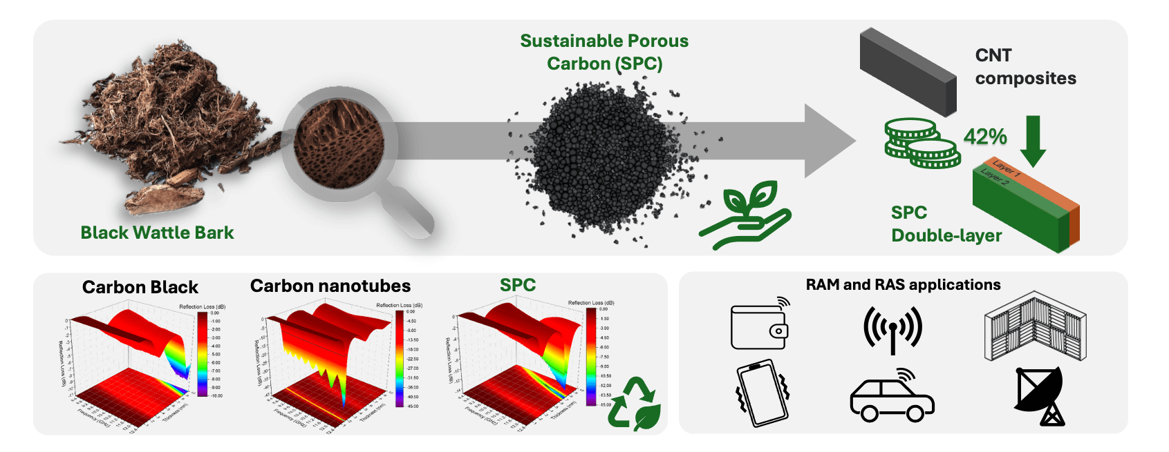
Radar Absorbing Materials (RAM) are a class of composites that can attenuate incident electromagnetic waves to avoid radar detection. Most carbon allotropes that have the potential to be used as RAM are either carbon nanotubes (CNTs), graphene, carbon black (CB) and ultimately, sustainable porous carbon (SPC). Here, black wattle bark waste (following tannin extraction) was used as a sustainable source to produce SPC made from biomass waste. It was characterized and used as a filler for a silicone rubber matrix to produce a flexible RAM. The electromagnetic performance of this composite was compared with composites made with commercial CB and CNT through reflection loss (RL), where −10 dB is equivalent to 90% of attenuation. These composites were evaluated in single-layer, double-layer, and as radar absorbing structures (RAS) with the aim of improving their effective absorption bandwidth (EAB) performances and a reduction in costs. The CNT composite presented a RL of −26.85 dB at 10.89 GHz and an EAB of 2.6 GHz with a 1.9 mm thickness, while the double-layer structures using CNT and SPC provided a RL of −19.74 dB at 10.75 GHz and an EAB of 2.51 GHz. Furthermore, the double-layer structures are ~42% cheaper than the composite using only CNT since less material is used. Finally, the largest EAB was achieved with a RAS using SPC, reaching ~2.8 GHz and a RL of −49.09 dB at 10.4 GHz. Summarizing, SPC made of black wattle bark waste can be a competitive, alternative material for use as RAM and RAS since it is cheaper, sustainable, and suitable for daily life uses such as absorbers for anechoic chambers, sensors, and electromagnetic interference shields for electronics, wallets, vehicles, and others.Graphic Abstract
Keywords
Nomenclature
| CB | Carbon black |
| CB-C | Carbon black composite |
| CNT | Carbon nanotube |
| CNT-C | Carbon nanotube composite |
| EAB | Effective Absorption Bandwidth |
| EMI | Electromagnetic Interference |
| RAM | Radar Absorbing Materials |
| RAS | Radar Absorbing Structures |
| RL | Reflection loss |
| SBET | Specific surface area |
| SPC | Sustainable porous carbon |
| SPC-C | Sustainable porous carbon composite |
| SR | Silicon rubber |
| VDR | Volumes of micropores |
| Vmeso | Volumes of mesopores |
| Vtotal0.99 | Total volume of pores |
| e.g. | |
| Z | Material impedance |
| | Relative complex permittivity |
| | Relative complex permeability |
Radar absorbing materials (RAM) are a class of engineered materials able to attenuate an incident wave by converting electromagnetic energy into thermal energy through dielectric or magnetic losses [1]. RAMs became famous for their use in stealth technology, usually in combat aircraft, to minimize their radar cross-section and avoid detection [2]. Research in this area always seeks to develop thin, light, and broadband materials. Although this material is usually used for military purposes in several frequency bands [3], it can also be used for other applications, such as electromagnetic shields for electronics [4], radomes for space science [5], energy harvesting [6], satellites [7], among others.
The main use of RAM described in the literature so far is for stealth technology [2], which requires a thinner, broadband, high-absorptive material regardless of costs or sustainability. Carbon nanotubes or highly ordered carbons, such as graphene, are the logical choice to develop and design novel materials with large effective absorption bandwidths (EAB). However, because of their military application, the best materials developed for this purpose would not be published, nor promptly available to society.
Jia et al. [1] emphasized that future studies of RAM may pay more attention to applications for extreme conditions, like high temperatures, or focus on daily life applications. The most straightforward application for RAM is electromagnetic interference (EMI) shielding. Several researchers have demonstrated how RAM and radar absorbing structures (RAS) can provide good shielding effectiveness to prevent electromagnetic interference [8–11]. There is still room for advancement in this area regarding materials, such as application methods like thermal spray coating that is industrially viable [12]. In an increasingly wireless world, the need for RAM for EMI shielding will increase. They can be applied to wallets or pouches to protect contactless credit cards, car keyless or radio key systems [13]. The Internet of Things is becoming more present in daily life, reaching smartphones, smart homes, autonomous cars [14], and so on. RAM can be an interesting substitute for metallic parts to prevent EMI, since they are lighter. They can also be used as electromagnetic shielding for strollers [15] or railway vehicles [16].
An indirect use for RAM is in space science. RAM/RAS could be used to provide thermal protection for spacecraft during the re-entry phase while at the same time protecting internal components from EMI [17]. RAM could also be used to reduce the scattering in metallic frames of radomes [5]. Combining RAM with frequency-selective surfaces allows the development of stealth radomes [18], but such designs could also be used as bandpass filters [19]. Another use of absorbing material in this area can be an alternative to the pyramidal foams inside anechoic chambers. RAS using sustainable carbon could increase the workspace, reduce costs, help the environment, and reduce the chamber’s inner side.
RAM and RAS could be used as sensors, where detection can be made through resonance frequency shifting, similar to metamaterial absorber sensors [20,21]. Another interesting application was described by Song et al. [22]: biomass carbon-based RAM for energy harvesting. Ren et al. [23] also considered RAM for microwave energy harvesting. In the future, applying RAM to clothes [24] may provide not only EMI protection for pacemakers [25] but could be used as sensors [26] or energy sources.
Wang et al. [27] related how the results of current research are far from being used since many studies focus on pure microwave absorption powders. Advances in materials have mainly been around the fillers, but extraordinary results using paraffin should have few, if not say no, applications at all. It is important to use practical matrixes, but innovation in fillers can be achieved, especially when using waste materials, since they are sustainable, cheap, and environmentally friendly. For example, intensive care units may have equipment susceptible to radio frequencies, where EMI would be disastrous. RAM/RAS using sustainable carbon could provide light, cheap, and effective EMI shielding.
Over the decades, several potential types of RAM have been studied, such as carbon allotropes [17,28] like carbon nanotubes (CNT), carbon black (CB), ferrites [29], and silicon carbide [30]. Carbon was the first material discovered that attenuated an electromagnetic incident wave [28]. The absorption mechanism studied back then was the conversion of electromagnetic energy into heat, dissipating the energy, and avoiding detection through reflection. Today, it is known that other phenomena can attenuate an incident wave, like impedance matching, polarization loss, conduction loss, and magnetic loss [27]. Moreover, single-layer RAM cannot attenuate an incident wave over an extensive frequency range, but there are strategies to broaden their effective absorption bandwidth (EAB), i.e., the frequency range that lies below −10 dB. These strategies are multilayer structures [31], frequency selective surfaces [32], metamaterials [33], and RAS [34]. Green et al. [35] stated that a large EAB should be prioritized rather than an extremely low reflection loss (RL), since astronomical RL values may be derived from input parameters, such as an increased precision thickness.
RAS can be developed with highly electric conductive materials like CNT or graphene, but they are expensive, difficult to produce, and use chemicals that are hazardous to the environment. Commercial applications may benefit from the development of environmentally friendly and low-cost manufacturing approaches [36], and incorporating porous structures of dielectric lossy fillers may be an alternative to reduce weight [36]. A cheap, sustainable alternative is biobased carbon, i.e., carbon derived from biomass residues. Although biobased carbon does not provide a conductivity as high as CNT or graphene, it can be engineered to increase its conductivity and porosity through the activation process or heteroatoms/metallic doping. Several biomaterials have already been explored as RAM, such as wheat [37], rice [38], coconut coir [39], shaddock peel [40], black liquor [41], and others. Such materials could be developed into RAS, but whether this would produce biobased carbons as competitive as CNT and to what uses they could be made is unknown.
This manuscript presents a novel Sustainable Porous Carbon (SPC) made from the solid waste generated after tannin extraction from black wattle bark. The electromagnetic properties and performance of SPC composites were compared to composites made with commercial Carbon Black (CB) and CNT. All composites were made with silicone rubber to provide flexibility. They were investigated in the X-band frequency range and single-layer, double-layer, and RAS were compared. The result of this study shows that SPC RAM can be engineered to provide a broadband reduction of the reflected electromagnetic wave, reducing production costs and aiding the environment by reusing industrial waste to combat electromagnetic pollution.
Commercial multiwall CNT from Cheap Tubes Inc. (Grafton, VT, USA), carbon black from Cabot (Boston, MA, USA), and black wattle bark waste after tannin extraction, were kindly provided by TANAC S.A. (Rio Grande do Sul, Brazil). All composites were made with white silicone rubber (SR) and its catalyzer from Redelease SA (Sao Paulo, Brazil).
2.1 Preparation of Sustainable Porous Carbon
The bark waste from tannin extraction was submitted to carbonization without previous preparation. It was carbonized in a horizontal tubular furnace EDG10P-S (EDG, Brazil), at 900°C under argon for 2 h, with a heating rate of 5°C/min. The SPC was manually ground in a mortar to reduce its particle size.
2.2 Preparation of Carbon Composites
The composites were prepared to reach the saturation limit, i.e., the maximum volume of filler that could be mixed with silicone rubber without spoiling its curing. The composites using CNT and CB were prepared with 3 wt% of each carbon allotrope and named CNT-C and CB-C, respectively. The SPC composite (SPC-C) was prepared with 20 wt% of the carbonized material. All composites went through the same fabrication process. They were manually mixed until complete homogenization, the catalyzer was then added, and finally, the mixtures were placed in a 22.86 × 10.16 × 6.00 mm X-band mold. The samples were left to dry overnight.
2.3 Morphological Characterization
The carbon materials were analyzed with a Field Emission Scanning Electron Microscope (FESEM) from Tescan model MIRA 3 (Tescan, Czech Republic). The SPC composition was analyzed through Energy-Dispersive Spectroscopy (EDS) with an X-MAX 50 device (Oxford, United Kingdom). The adsorption-desorption and the pore volume of SPC, CNT and CB were calculated through BET analysis using an ASAP 2020 Plus (Micromeritics, USA). The degree of graphitization of the carbonized material was confirmed through Raman spectroscopy measured with a LabRam HR Evolution (Horiba, Japan) and a green laser of 514.5 nm wavelength. The materials loose bulk and skeletal density were measured by an ASTM D7481-18 and a helium pycnometer analyzer model Ultrapycnometer 1200e (Quantachrome, USA), respectively.
2.4 Electromagnetic Characterization
The electromagnetic properties of all composites were measured with a vector network analyzer, Agilent Technologies N5230C, coupled with the X-band rectangular waveguide X11644A. Since all samples are dielectric, a precision mode method was used to calculate only the permittivity, considering that the complex permeability equals μ = 1-i0. The reflection loss was calculated using [42]:
where the impedance between air and the material (
and
The multilayer structure uses a similar equation [43,44], where
and the impedance between the first and second layer (
where
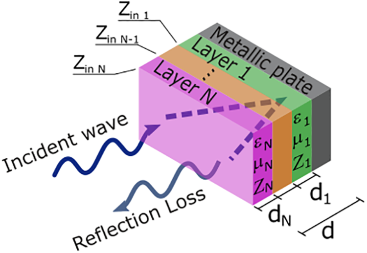
Figure 1: Multilayer structure
The RAS design was based on the work of Fang et al. [45]. This design was chosen because it is one of the fewer designs found in the literature based purely on sustainable material, to the best of our knowledge. The rectangular structure is presented in Fig. 2. Since the optimization of the RAS is out of the scope of this work, the parameters of the design were slightly adapted to provide a large EAB. The parameters used were a1 = 43 mm, a2 = 16.1 mm, a3 = 0.8 mm, h1 = 2.5 mm, h2 = 6.5 mm.
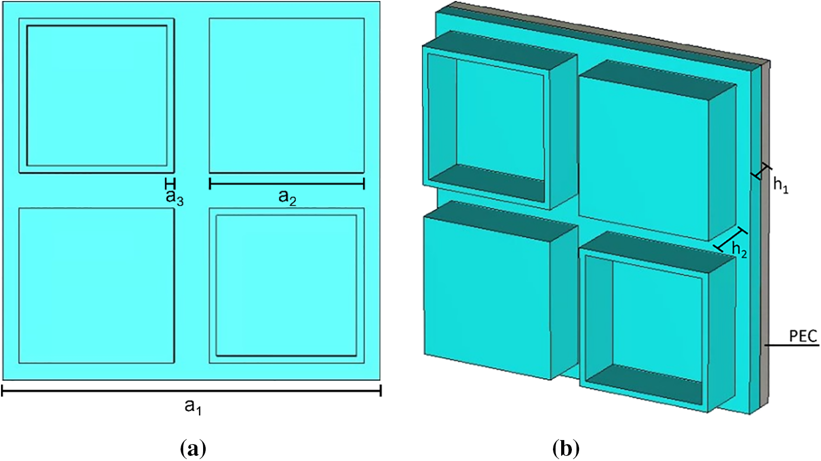
Figure 2: (a) Top and (b) perspective view of the simulated RAS based on the work of Fang et al. [45]
All simulations were executed in CST software using the frequency solver based on the Finite Elements Method (FEM). A unit cell boundary condition was used to simulate a periodic structure and the solver accuracy was set to 10−4.
3.1 Morphological Measurements
The FESEM images at different magnifications show the typical structures of the studied carbons in Fig. 3. The morphology of CNT was composed of tangled and cylindrical nanostructures (Fig. 3a,d) that were curl and divergence-free on the surface of the carbon cloth. FESEM images of CB are shown in Fig. 3b,e, a cluster of carbon nanospheres in the form of particles and aggregates. Finally, Fig. 3c,f shows the carbonaceous structure of bark waste after carbonization in which an anisotropic cellular structure characteristic of biobased carbons is seen. During carbonization, a porous structure is developed as a result of the thermochemical degradation process but the wood walls, mainly formed by cellulose, hemicellulose, and lignin [46], responsible for providing structural support, fluid conduction, or storage of sugars [47], are not destroyed. This observation confirmed the results of the analysis of the porous structure of the activated generated carbon.

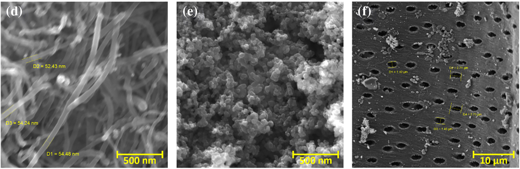
Figure 3: FESEM images of (a) CNT, (b) CB, and (c) SPC with their respective close-ups in (d–f)
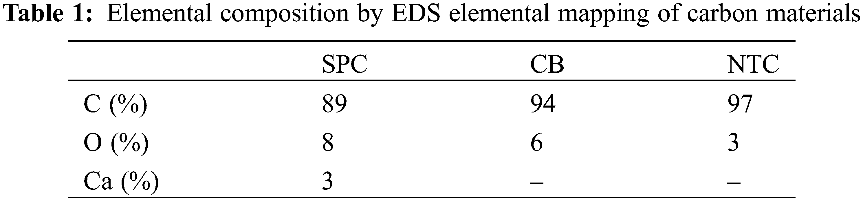
The elemental composition of bark derived from Acacia species [48] is approximately 44% carbon, 8% hydrogen, and 1% nitrogen, the remaining content (47%) is mainly oxygen with a small amount of ash. After thermochemical degradation, the percentage of carbon is increased, whereas the other elements are reduced. The Energy-Dispersive Spectroscopy (EDS) analysis of the SPC, CB, and CNT (Fig. 4) reveals an elemental composition mainly formed by carbon and oxygen, the main components present in these carbonaceous materials. A small proportion of calcium in SPC is also typically found in wood-based carbons [49] (Table 1). According to the literature, bark trees contain a substantial fraction of the nutrients stored in woody biomass [50–52]. Jones et al. found several nutrients or inorganic elements in bark from 23 trees, and calcium had the highest variation between those species which were correlated with soil nutrients. In contrast, CB and NTC are mainly composed of carbon: 94% and 98%, the rest being 6% and 3% oxygen, respectively.

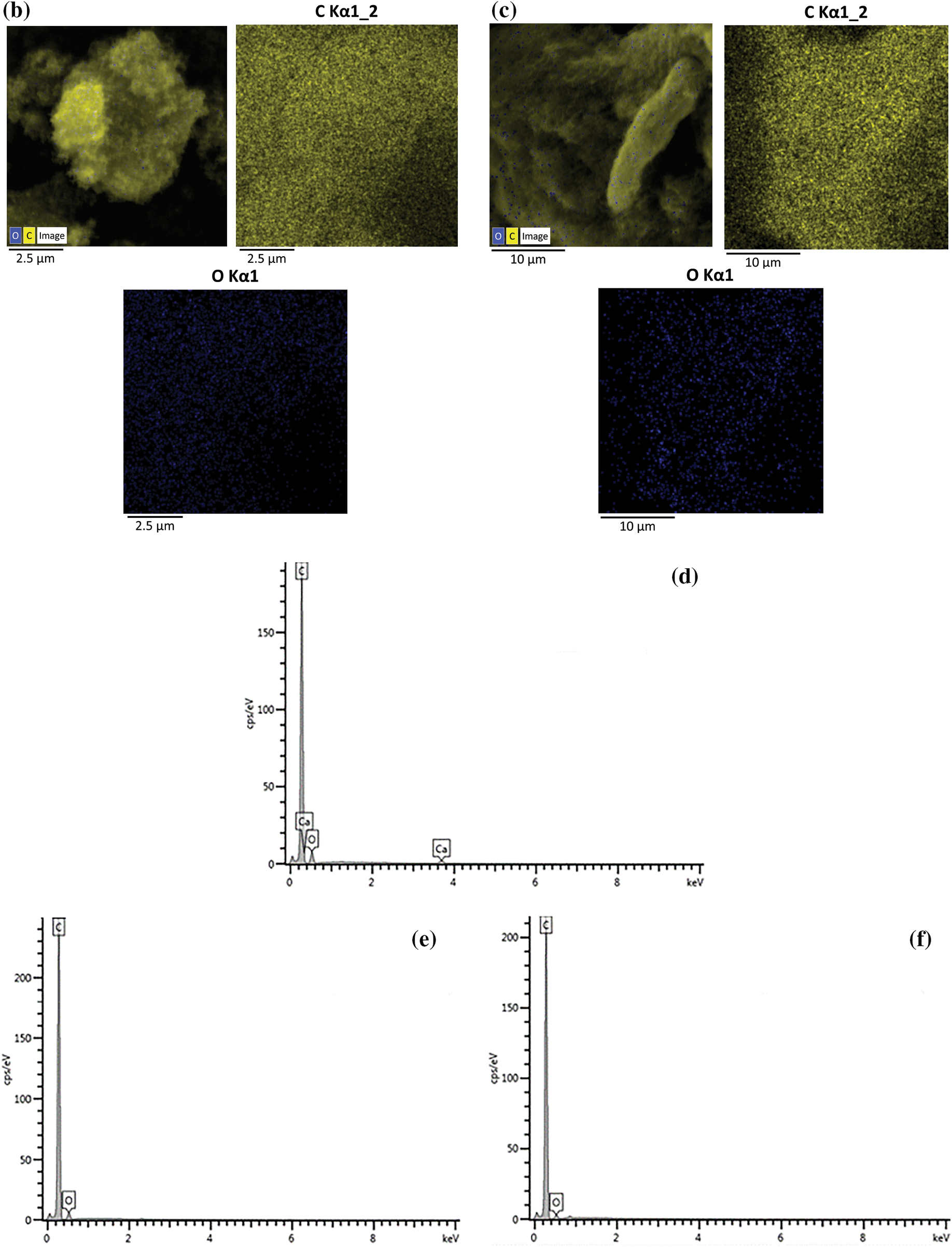
Figure 4: (a, b, c) EDS elemental mapping analysis with highlights of carbon, oxygen and calcium of SPC (a), carbon and oxygen of CB (b), carbon and oxygen of CNT (c). (d, e, f) Spectrum of elements showing the main peaks of SPC (d), CB (e) and CNT (f)
Nitrogen adsorption-desorption curves of the porous carbon materials showed a typical microporous structure for bark-carbon based SPC and a mesoporous structure for CNT and CB, presenting Type I and Type IV isotherms [53], respectively (Fig. 5a). The SPC had the largest surface area (300 m2/g) and the greatest volume of micropores (66%) compared to mesopores (34%) (Table 2). Indeed, during the carbonization of wood-based materials, several reactions take place, such as dehydrogenation, condensation, hydrogen transfer, and isomerization [54]. The heat treatment under an inert atmosphere maximizes the lignocellulosic precursor loss volume by a contraction process controlling the morphology and pore structure of porous carbon materials.
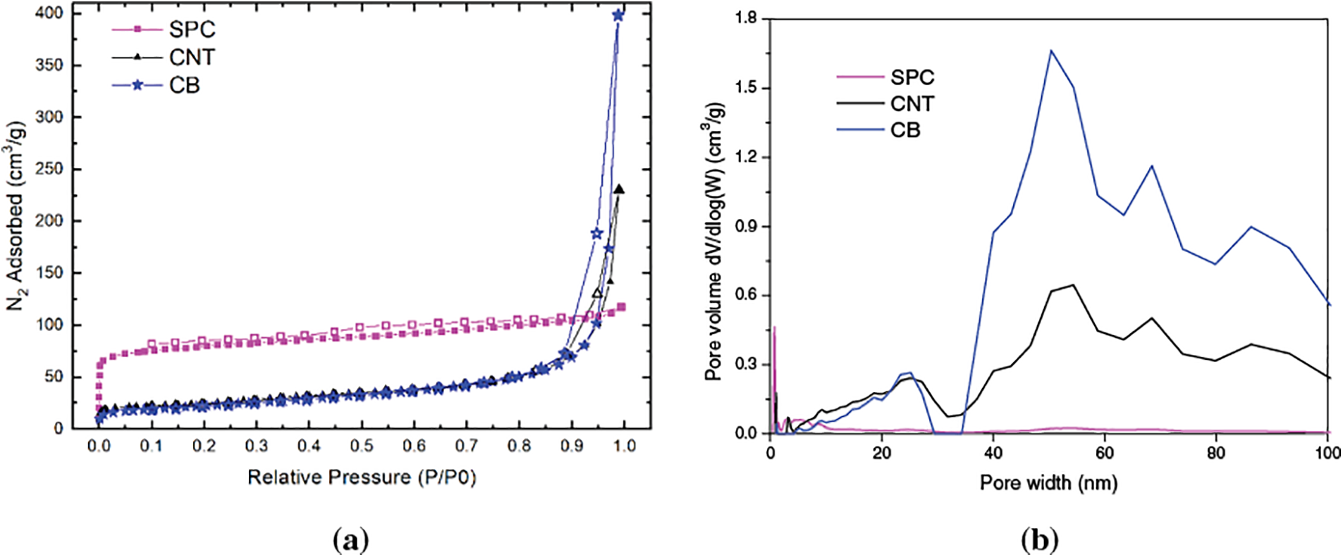
Figure 5: (a) Adsorption-desorption isotherms of carbon materials and (b) their respective pore size distribution calculated by density functional theory (DFT) method
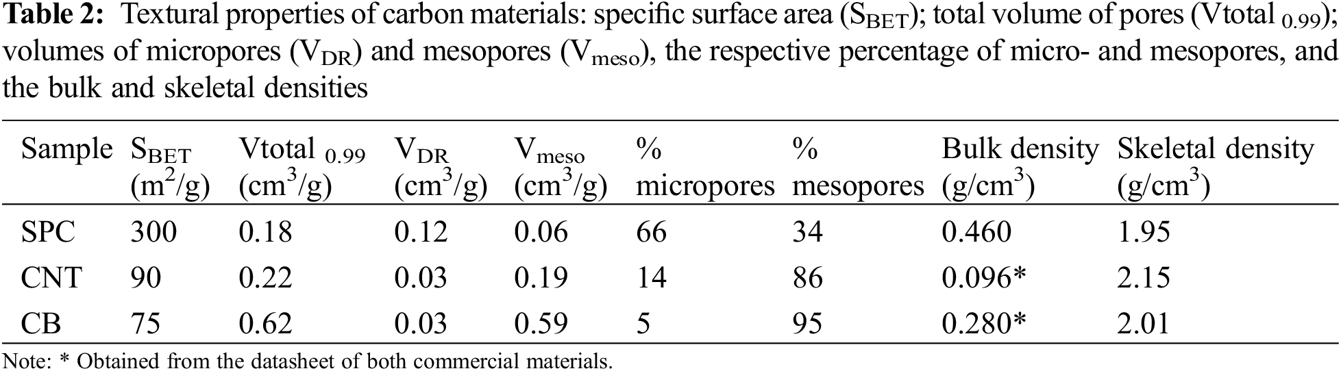
CNT and CB showed similar surface area values, but different amounts of micro- (14 and 5%, respectively) and mesopores (86 and 95%, respectively). It is interesting to note that the three carbon materials studied have different porous structures and surface areas available. The SPC presents a peak pore centered at 0.65 nm, and most of the pores are less than 7 nm (Fig. 5b). CNT and CB are mostly mesoporous, in agreement with the isotherms. The CNT concentrates the pores from 3 to 100 nm, and CB from 10 to 100 nm. Therefore, the CB is essentially mesoporous (95%) and has the largest pores. Therefore, the rough surface of porous carbon can create a conductive net that may attenuate the electromagnetic wave through eddy current loss [3], conductive loss, or enhanced space charge polarization [55]. Besides, the large porosity can be used to control the material permittivity through Maxwell-Garnett relationship [56], allowing the enhancement of impedance matching and further the electromagnetic attenuation.
The Raman spectra (Fig. 6) shows a very high second-order graphitization for CNT, while CB and SPC have no second-order peaks. All spectra show the typical D peak band at 1345 cm−1, generally attributed to a disordered structure or defects corresponding to the vibration of sp3 carbon atoms [57,58]. CNT presents a G band at 1571 cm−1, more elevated than the D band, indicating a high graphitization level. The peak of the D band indicates that there may be defects in the walls of the CNT [59]. The G band is related to the carbon sp2 bond in the structure [60]. The CNT spectrum also has another peak, G’, at 2690 cm−1. This peak is associated with the scattering mechanisms of the two-phonons, characterized by the double resonant scattering Raman process [59,61–63], and a peak centered at 2917 cm−1 may be associated with the combination of D+G [64]. The CB spectrum shows the peak of the G band at 1586 cm−1 and presents two peaks with values analogous to a highly disordered graphitic structure [64]. The SPC spectrum shows the G band’s peak at 1589 cm−1, associated with the graphitic structure [65]. The graphitization degree of CNT, CB, and SPC was estimated by the ratio between the D and G bands (ID/IG) [59]. The calculated ID/IG ratios showed that CNT had the highest structural organization (0.54), compared to the other materials, with CB and SPC being 0.88 and 0.94, respectively. Thus, the latter had the lowest degree of graphitization [66].
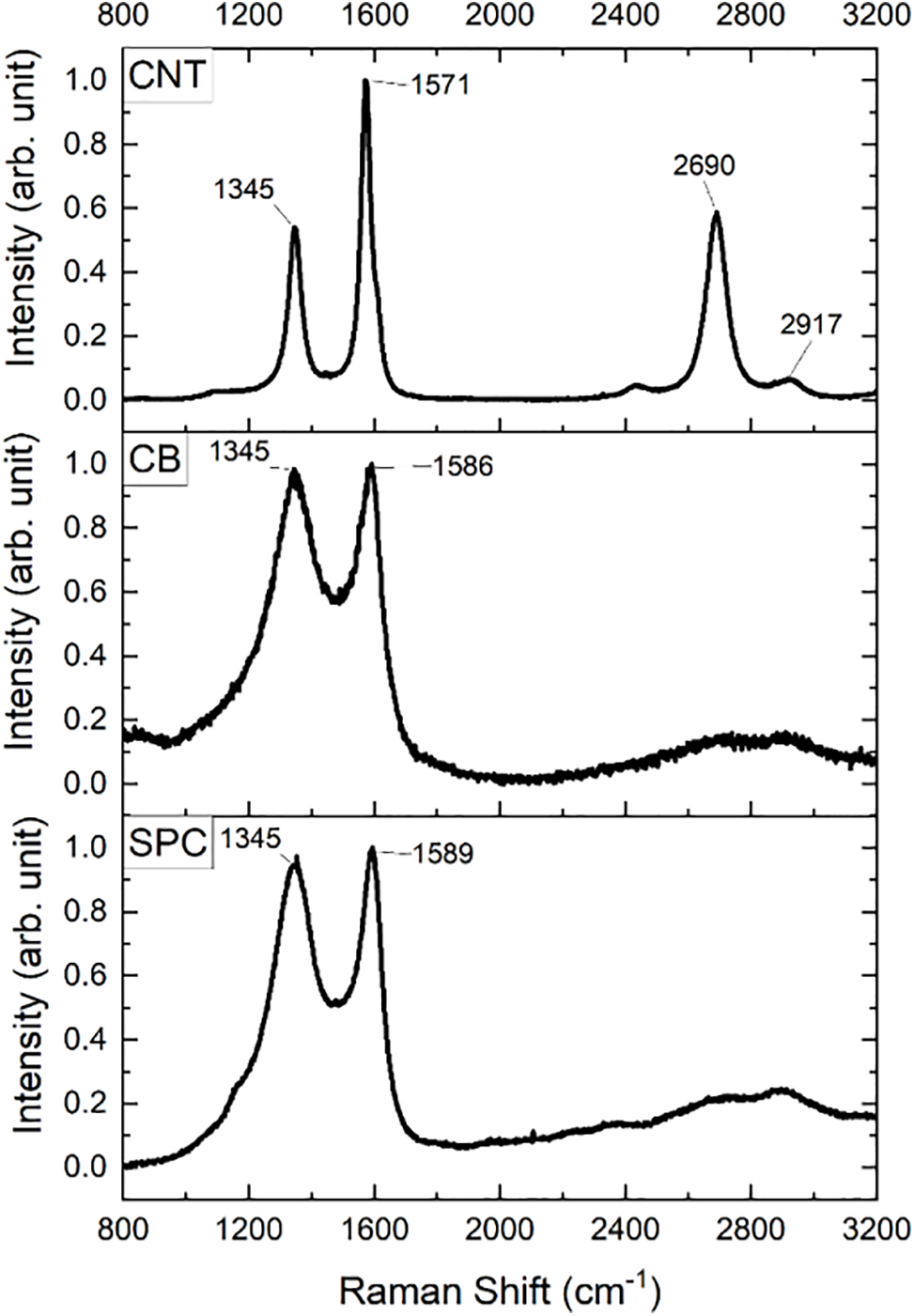
Figure 6: The Raman spectra of CNT, CB, and SPC
3.2 Electromagnetic Measurements
The averaged measured complex permittivity of the CNT, CB, and SPC composites is shown in Fig. 7, while the permittivity of each sample with its respective thickness is presented in Fig. A1 in the Appendix A. The permittivity of a blank SR is shown as a reference. The complex permittivity is given by ε = ε′-iε′′, where the real part is related to dielectric storage and the imaginary part to dielectric losses. Since all samples are dielectric, the permeabilities of all composites are close to 1 and therefore not presented. The solid lines in the graph are the real permittivities and the dashed lines are the imaginary permittivities. The shaded background in each line represents its standard deviation. The SR has the lowest real permittivity and presents no losses, ≈3.0-0.0i. The composite made with CB has a complex permittivity close to ≈4.0-0.5i, while the composite made with SPC has a complex permittivity of ≈6.5-0.5i. The composite made with CNT has a real permittivity starting at 14 and ending at ~13.5. The imaginary permittivity of CNT-C is the highest among all samples, starting at 4 and ending at 4.5. SPC-C and CNT-C have the most significant standard deviations because the amount of filler inserted is close to the saturation limit, i.e., the maximum amount of filler that can be added into the silicone rubber matrix. This led to a curing process that was faster than for the other samples and caused a surface rugosity, where the thickness had minor variations over the sample. Because of the soft nature of the silicone rubber composite along with the surface rugosity of each sample, there is a small imprecision during the thickness measurements using a caliper, resulting in a difference in the permittivity analysis.
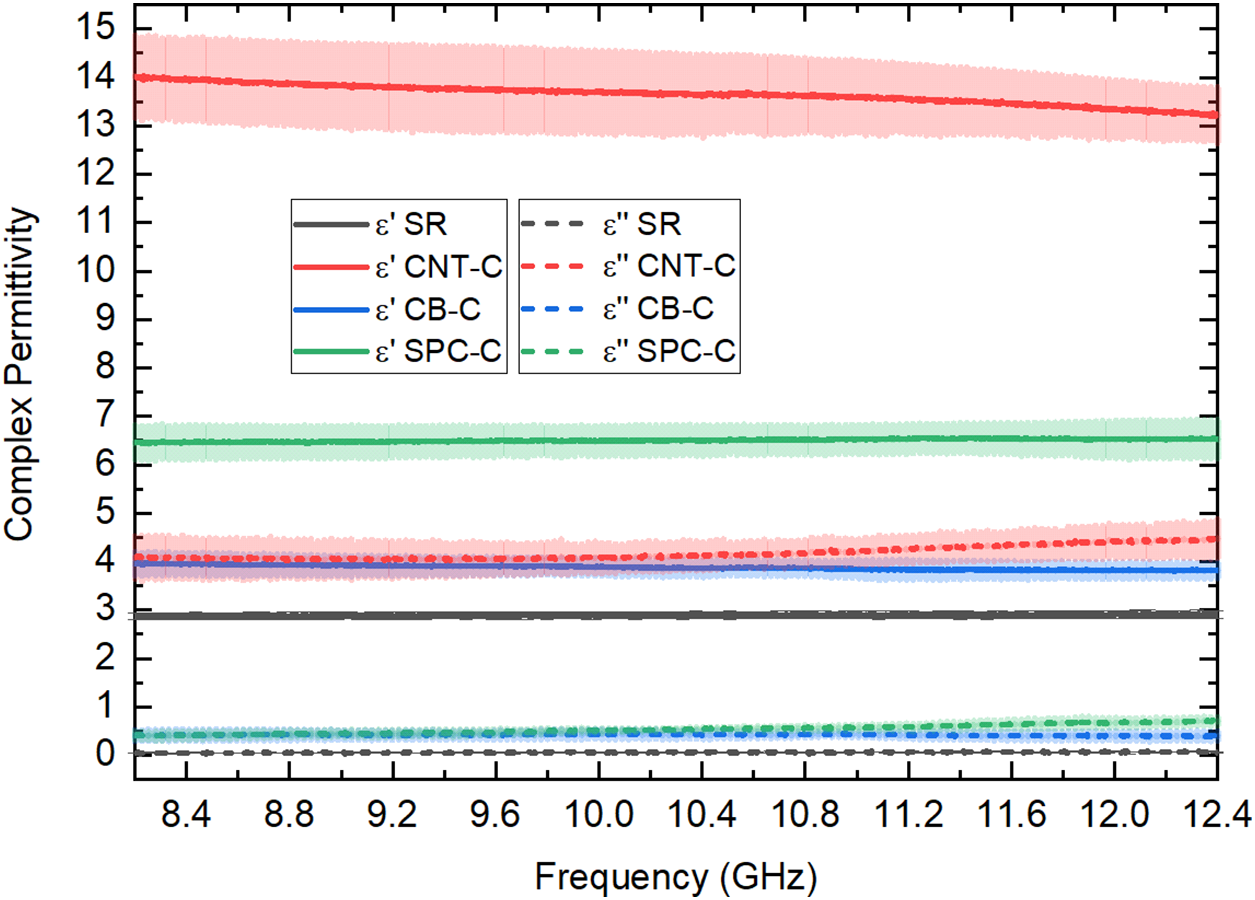
Figure 7: Complex permittivity of composites made with CNT, CB, and SPC. The complex permittivity of blank SR is presented as a reference
Silicone rubber is an electric insulator material that reduces the conductive property of the carbon filler. It is necessary to use a large amount of filler to overcome the insulating properties of SR, but the hydrophobic nature and light weight of CNT and CB prevent this from happening. The bulk density of SPC (0.460 g/cm3) is 1.6 and 2.9 times higher than CB and CNT, respectively, which allows a large amount of material to be mixed without compromising the curing process of the composite. Also, the hydrophobicity of SPC is lower than that of CNT and CB due to the low level of oxygenated compounds connected to its surface. This will probably be an advantage for a better interaction between the polymer and the SPC filler compared to the other composites prepared in this study. Furthermore, the material porosity helps it to be lighter and can be used to control the permittivity through the Maxwell-Garnett relationship. When the incident wave passes through the composite, each grain of porous carbon develops an electric charge. If the porous carbon is more conductive, the electrical current running through it would be dissipated as heat, increasing the imaginary permittivity of the material. Indeed, the porosity could be used to allocate other materials inside the carbon, like metallic ions, which would increase the complex permittivity of the composite [67].
The RL for all samples was calculated using the averaged permittivity of each sample in Eqs. (1) and (2). The results are presented in the 3D graph in Fig. 8. SR and CB-C, Fig. 8a,b, do not show a significative RL for samples up to 10 mm thick. CNT-C has an RL of −39.6 dB at 12.31 GHz and an EAB of ~1.4 GHz for the 1.7 mm sample. The best EAB acquired with CNT-C is for the 1.9 mm thick sample, which has a RL of −26.85 dB at 10.8 GHz and an EAB of 2.6 GHz. The 7.2 mm thick SPC-C sample reaches −13.34 dB at 12.32 GHz and an EAB = ~0.5 GHz. It is interesting to note how the CNT-C is sensitive to thickness compared with SPC-C, requiring a very precise thickness to achieve a RL at a specific frequency.
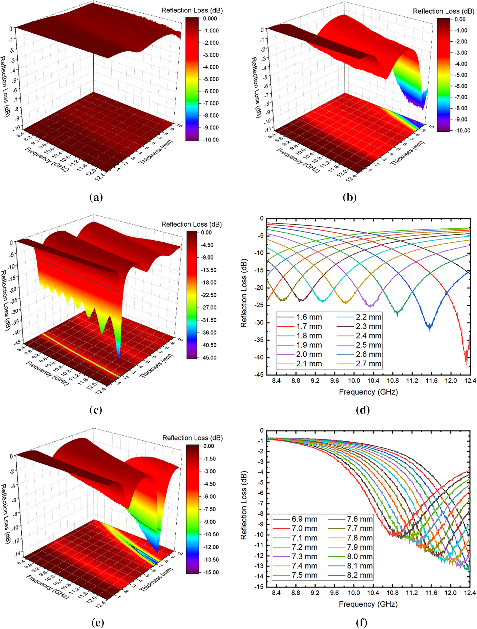
Figure 8: 3D RL of (a) SR, (b) CB-C, (c) CNT-C with (d) the best results in 2D, and (e) SPC-C with (f) the best results in 2D
3.3 Double Layer and RAS Reflection Losses
Although CB demonstrated no significant RL by itself, it can still find use as an absorbent material. This is demonstrated in Fig. 9, where different results for the double-layer structure are presented. Fig. 9a is a double-layer structure with 1.1 mm of CNT-C and 0.9 mm of CB-C and an RL of −20.7 dB at 10.9 GHz. The EAB of this double layer is 2.59 GHz, which is slightly better than the double layer using SPC-C as the second layer, with 2.51 GHz. Compared with the RL of CNT-C in Fig. 9b, the double layer using CB-C provides a smaller RL, but the absorption peak and the EAB happens at the same frequency. Since EAB is the parameter that should be maximized [35], a double layer that can provide the same EAB using less CNT with a trade-off of being only 0.1 mm thicker is attractive. Considering that CNT is much more expensive than CB, when reducing the thickness of the CNT-C from 1.9 to 1.1 mm means that only ~58% of the CNT-C would be required. Since the filler is the main product that drives the costs of the composites, a reduction of approximately 42% in sample thickness would correspond to an estimated 42% savings in the final price. Also, a double-layer structure would be easier to tune than a single-layer CNT-C, as seen in Fig. 9c. Increasing the thickness of CB-C by 0.2 mm in the double-layer structure shifted the RL from 10.9 GHz to 10.0 GHz, while it would require a precise thickness to shift the same amount using only CNT-C.
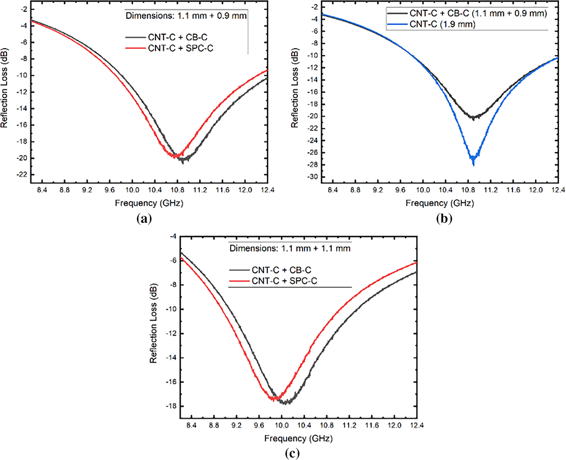
Figure 9: (a) Reflection loss of double-layer structures with a total thickness of 2.0 mm with the first layer as CNT-C and the second layer as CB-C or SPC-C. (b) Comparison of the single-layer CNT-C of 1.9 mm and the double-layer of 2.0 mm with CNT-C and CB-C. (c) Demonstration of tuning the reflection loss by increasing the thickness of the second layer
The double layer presented is effective in reducing costs, but it does not enlarge the EAB. It is necessary a thicker multilayer structure to increase the EAB to the whole X-band frequency range. Fig. 10 presents the RL for three different multilayer structures. The first one (black line) is a double-layer structure with total thickness of 9.0 mm, consisting of 3.7 mm CB-C and 5.3 mm CNT-C. The second structure (red line) is a triple-layer with 2.6 mm CB-C, 0.7 mm SPC-C, and 5.5 mm CNT-C, totalizing an 8.8 mm thickness. Lastly, the third design (blue line) has a total thickness of 8.4 mm, with layers of 1.1, 1.5, and 5.8 mm of SPC-C, SR, and CNT-C, respectively.
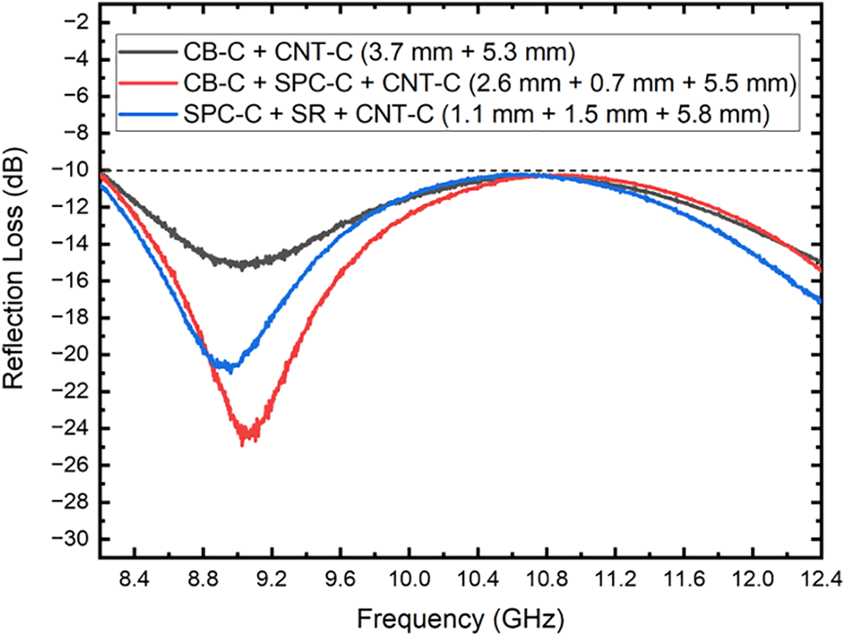
Figure 10: RLs of multilayer absorbers designed to provide an EAB over the entire X-band frequency range
A broadband EAB using only one material can be achieved with RAS. Fig. 11 shows the RL of RAS based on the design of Fang et al. [45], which made a RAS with almond shells and paraffin, and optimized the design through software. The CB-C barely reaches −10 dB at the center of the frequency band, and the CNT-C reaches −10 dB beyond 10.4 GHz. Here, SPC-C has an EAB of ~2.8 GHz, and the RL reaches −49.09 dB at 10.4 GHz. This result proves that even though the sustainable composite material does not have the highest graphitization ratio or a higher oxygen content present on its surface, it could be designed to achieve RL and EAB comparable to great well performing materials such as carbon nanotubes and carbon black.
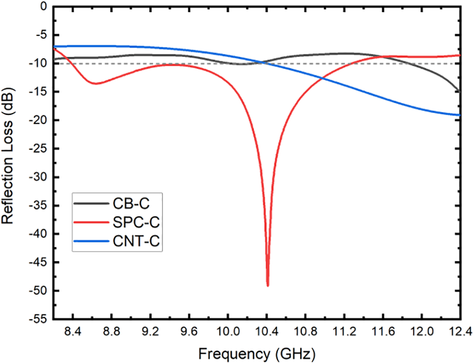
Figure 11: RL of CB-C, SPC-C, and CNT-C as RAS
3.4 Cost Analysis of Carbonaceous Materials
The production cost ($US/kg) of activated carbon is calculated based on several parameters. The most important factors include the total fixed cost (plant overheads, taxes, and royalties), the total variable cost (raw material, consumables, physicochemical activation agents’ costs), and the total general expenses (administration cost, research and development, and distribution and sales) accounting for approximately 32%, 13%, and 55% of the total cost, respectively [68]. For example, the production cost of wood-based activated carbon material, assuming zero raw material costs through a plant capacity of 4.5 tons per day, would be 2.49 $US/kg for physical activation and 1.80 $US/kg for chemical activation [68]. Therefore, considering a sustainable material produced in the same physical activation plant, the final price of sustainable porous carbon would be comparable or even cheaper to that of the commercial activated carbon because SPC in this study was not physically or chemically activated.
Carbon black is a material mostly produced by the incomplete combustion of coal tar or petroleum products. It is considered a low-cost carbonaceous material [69]. However, it presents negative implications for human health and environment due to the high levels of CO2 generated through incomplete combustion of fossil fuels [70]. In contrast, carbon nanotubes (CNTs) have a significantly higher price compared to SPC and CB. For instance, the production cost of sustainable carbon depends on parameters such as the price of raw materials, plant capacity, and product yield [68]. On the other hand, the price of CNTs can vary significantly based on factors like surface functionalization, the number of walls, and other specifications. For a comparative estimation, the prices of a commercial activated carbon NORIT® RX3 EXTRA (901934-500G Sigma Aldrich/Cas Number: 7440-44-0) is 123.00 $US/0.5 kg whereas a multi-walled carbon nanotube (90% carbon basis, D × L 110–170 nm × 5–9 μm, 659258-10G Sigma Aldrich/Cas Number: 308068-56-6) is 396.00 $US/0.01 kg. Thus, carbon derived from biomass can be up to 160 times cheaper than carbon nanotubes, although this value can significantly vary depending on several factors mentioned above. This combination of sustainability and cost-efficiency underscores the advantage of using black wattle bark waste for producing porous carbon.
This study showed how a sustainable material made of black wattle bark waste can be used as filler for composites of radar absorbing materials (RAM) and to design radar absorbing structures (RAS). The CNT (Carbon nanotube) composite evaluated provided a thinner, more effective single-layer RAM, reaching −41.1 dB at 12.3 GHz with a 1.7 mm sample. The maximum effective absorption bandwidth (EAB) that could be achieved is 2.6 GHz with a 1.9 mm sample, which presented a reflection loss (RL) of −28.15 dB at 10.9 GHz. The double-layer structure using CB (carbon black) and CNT provided a similar EAB (2.59 GHz), with a RL of −20.7 dB at 10.9 GHz. This could reduce the costs by ~42% when compared with a single-layer CNT, since the double-layer structure has a CNT layer 1.1 mm thick and a CB layer of 0.9 mm. Also, similar results for a double-layer structure using sustainable porous carbon (SPC) and CNT were obtained, indicating that SPC could easily replace CB. The SPC composite demonstrated a superior RL and EAB when explored as a RAS. The RL of −49.09 dB at 10.4 GHz and the EAB of ~2.8 GHz were the best results obtained. This demonstrates how SPC composites can be an alternative material for civilian applications, such as replacements for electromagnetic foam absorbers inside anechoic chambers, space science, sensors, energy harvesting, and electromagnetic interference shielding for electronics, purses, wallets, and vehicles.
Acknowledgement: Alan F. N. Boss thanks CAPES-PNPD for the financial support. Manuella G. C. Munhoz thanks CAPES-DS for the financial support. Gisele Amaral-Labat and Rodrigo G. A. Lima thank CNPq for the financial support. Leonardo I. Medeiros and Nila C. F. L. Medeiros thank UESC and INPE. All authors thank Mauricio R. Baldan for his kind permission to use his laboratory.
Funding Statement: The authors received no specific funding for this study.
Author Contributions: The authors confirm contribution to the paper as follows: study conception and design: Alan F. N. Boss; material development: Manuella G. C. Munhoz; morphological data collection and interpretation of results: Gisele Amaral-Labat, Beatriz C. S. Fonseca, Leonardo I. Medeiros, Nila C. F. L. Medeiros; electromagnetic data collection: Leonardo I. Medeiros, Nila C. F. L. Medeiros; electromagnetic simulations: Rodrigo G. A. Lima; electromagnetic interpretation of results: Alan F. N. Boss, Rodrigo G. A. Lima, Leonardo I. Medeiros, Nila C. F. L. Medeiros; draft manuscript preparation: Alan F. N. Boss, Gisele Amaral-Labat, Flavia L. Braghiroli; review and editing final version: Alan F. N. Boss, Gisele Amaral-Labat, Flavia L. Braghiroli; resources and supervision: Guilherme F. B. Lenz e Silva. All authors reviewed the results and approved the final version of the manuscript.
Availability of Data and Materials: Data can be available on request.
Ethics Approval: Not applicable.
Conflicts of Interest: The authors declare that they have no conflicts of interest to report regarding the present study.
References
1. Jia Z, Lan D, Lin K, Qin M, Kou K, Wu G, et al. Progress in low-frequency microwave absorbing materials. J Mater Sci: Mater Electron. 2018;29(20):17122–36. doi:10.1007/s10854-018-9909-z. [Google Scholar] [CrossRef]
2. Ahmad H, Tariq A, Shehzad A, Faheem MS, Shafiq M, Rashid IA, et al. Stealth technology: methods and composite materials—a review. Polym Compos. 2019;40(12):4457–72. doi:10.1002/pc.25311. [Google Scholar] [CrossRef]
3. Ruiz-Perez F, López-Estrada SM, Tolentino-Hernández RV, Caballero-Briones F. Carbon-based radar absorbing materials: a critical review. J Sci: Adv Mater Devices. 2022;7(3):100454. doi:10.1016/j.jsamd.2022.100454. [Google Scholar] [CrossRef]
4. Bontaş MG, Diacon A, Călinescu I, Necolau MI, Dinescu A, Toader G, et al. Epoxy coatings containing modified graphene for electromagnetic shielding. Polymers. 2022;14(12):2508. doi:10.3390/polym14122508. [Google Scholar] [PubMed] [CrossRef]
5. Zhang CF, Tang W, Mi XL, Chen LR. Application of radar absorbing material in design of metal space frame radomes. In: Proceedings of 2011 Cross Strait Quad-Regional Radio Science and Wireless Technology Conference; 2011; Harbin: IEEE, p. 222–5. doi:10.1109/CSQRWC.2011.6036926. [Google Scholar] [CrossRef]
6. Lv H, Yang Z, Liu B, Wu G, Lou Z, Fei B, et al. A flexible electromagnetic wave-electricity harvester. Nat Commun. 2021;12(1):834. doi:10.1038/s41467-021-21103-9. [Google Scholar] [PubMed] [CrossRef]
7. Micheli D, Pastore R, Gradoni G, Mariani Primiani V, Moglie F, Marchetti M. Reduction of satellite electromagnetic scattering by carbon nanostructured multilayers. Acta Astronaut. 2013;88(2):61–73. doi:10.1016/j.actaastro.2013.03.003. [Google Scholar] [CrossRef]
8. Saini P, Choudhary V, Singh BP, Mathur RB, Dhawan SK. Polyaniline-MWCNT nanocomposites for microwave absorption and EMI shielding. Mater Chem Phys. 2009;113(2–3):919–26. doi:10.1016/j.matchemphys.2008.08.065. [Google Scholar] [CrossRef]
9. Sahu KR, De U. Polymer composites for flexible electromagnetic shields. Macromol Symp. 2018;381(1):1800097. doi:10.1002/masy.201800097. [Google Scholar] [CrossRef]
10. Oh J-H, Oh K-S, Kim C-G, Hong C-S. Design of radar absorbing structures using glass/epoxy composite containing carbon black in X-band frequency ranges. Compos Part B: Eng. 2004;35(1):49–56. doi:10.1016/j.compositesb.2003.08.011. [Google Scholar] [CrossRef]
11. Kumar GS, Patro TU. Efficient electromagnetic interference shielding and radar absorbing properties of ultrathin and flexible polymer-carbon nanotube composite films. Mater Res Express. 2018;5(11):115304. doi:10.1088/2053-1591/aade39. [Google Scholar] [CrossRef]
12. Faisal NH, Ahmed R, Sellami N, Prathuru A, Njuguna J, Venturi F, et al. Thermal spray coatings for electromagnetic wave absorption and interference shielding: a review and future challenges. Adv Eng Mater. 2022;24(7):2200171. doi:10.1002/adem.202200171. [Google Scholar] [CrossRef]
13. Joskiewicz Z, Janukiewicz J. Experimental study of the shielding effectiveness performance degradation for a shielding material used in protective storage pouch. EM: Proceedings of the 2020 International Symposium on Electromagnetic Compatibility (EMC Europe), 2020; New York: IEEE. [Google Scholar]
14. Boteanu A, Rastoceanu F, Radoi I, Rusea C. Modeling and simulation of electromagnetic shielding for IoT sensor nodes case. In: 2019 10th International Conference on Speech Technology and Human-Computer Dialogue (SpeD), 2019; New York: IEEE. [Google Scholar]
15. Dogan S, Kayacan O, Goren A. A lightweight, strength and electromagnetic shielding polymer composite structure for infant carrier strollers. Polym Compos. 2019;40(12):4559–72. doi:10.1002/pc.25324. [Google Scholar] [CrossRef]
16. Zhao T, Teng W, Hao H, Sun P, Liu Y. Simulation research on electromagnetic shielding characteristics of carbon fiber car body for railway vehicles. Procedia Comput Sci. 2019;154(4):537–42. doi:10.1016/j.procs.2019.06.085. [Google Scholar] [CrossRef]
17. Delfini A, Albano M, Vricella A, Santoni F, Rubini G, Pastore R, et al. Advanced radar absorbing ceramic-based materials for multifunctional applications in space environment. Materials. 2018;11(9):1730. doi:10.3390/ma11091730. [Google Scholar] [PubMed] [CrossRef]
18. Han Y, Chang Y, Che W. Frequency-selective rasorbers: a view of frequency-selective rasorbers and their application in reducing the radar cross sections of antennas. IEEE Microw Mag. 2022;23(2):86–98. doi:10.1109/MMM.2021.3125463. [Google Scholar] [CrossRef]
19. Costa F, Monorchio A. A frequency selective radome with wideband absorbing properties. IEEE Trans Antennas Propag. 2012;60(6):2740–7. doi:10.1109/TAP.2012.2194640. [Google Scholar] [CrossRef]
20. Bakır M, Karaaslan M, Unal E, Akgol O, Sabah C. Microwave metamaterial absorber for sensing applications. Opto-Electron Rev. 2017;25(4):318–25. doi:10.1016/j.opelre.2017.10.002. [Google Scholar] [CrossRef]
21. Sabah C, Turkmen-Kucuksari O, Turhan-Sayan G. Metamaterial absorber-based sensor embedded into X-band waveguide. Electron Lett. 2014;50(15):1074–6. doi:10.1049/el.2014.1753. [Google Scholar] [CrossRef]
22. Song Z, Sun X, Li Y, Tang W, Liu G, Shui J, et al. Carbon fibers embedded with aligned magnetic particles for efficient electromagnetic energy absorption and conversion. ACS Appl Mater Interfaces. 2021;13(4):5266–74. doi:10.1021/acsami.0c20522. [Google Scholar] [PubMed] [CrossRef]
23. Ren J, Yin J. 3D-printed low-cost dielectric-resonator-based ultra-broadband microwave absorber using carbon-loaded acrylonitrile butadiene styrene polymer. Materials. 2018;11(7):1249. doi:10.3390/ma11071249. [Google Scholar] [PubMed] [CrossRef]
24. Song W-L, Fan L-Z, Hou Z-L, Zhang K-L, Ma Y, Cao M-S. A wearable microwave absorption cloth. J Mater Chem C. 2017;5(9):2432–41. doi:10.1039/C6TC05577J. [Google Scholar] [CrossRef]
25. Palanisamy S, Tunakova V, Militky J, Wiener J. Effect of moisture content on the electromagnetic shielding ability of non-conductive textile structures. Sci Rep. 2021;11(1):11032. doi:10.1038/s41598-021-90516-9. [Google Scholar] [PubMed] [CrossRef]
26. Zhang W, Zhang X, Wu Z, Abdurahman K, Cao Y, Duan H, et al. Mechanical, electromagnetic shielding and gas sensing properties of flexible cotton fiber/polyaniline composites. Compos Sci Technol. 2020;188:107966. doi:10.1016/j.compscitech.2019.107966. [Google Scholar] [CrossRef]
27. Wang L, Li X, Shi X, Huang M, Li X, Zeng Q, et al. Recent progress of microwave absorption microspheres by magnetic-dielectric synergy. Nanoscale. 2021;13(4):2136–56. doi:10.1039/D0NR06267G. [Google Scholar] [PubMed] [CrossRef]
28. Qin F, Brosseau C. A review and analysis of microwave absorption in polymer composites filled with carbonaceous particles. J Appl Phys. 2012;111(6):061301. doi:10.1063/1.3688435. [Google Scholar] [CrossRef]
29. Meshram MR, Agrawal NK, Sinha B, Misra PS. Characterization of M-type barium hexagonal ferrite-based wide band microwave absorber. J Magn Magn Mater. 2004;271(2–3):207–14. doi:10.1016/j.jmmm.2003.09.045. [Google Scholar] [CrossRef]
30. Medeiros NC de FL, Medeiros LI de, Souza AAT de, Silva GFBL e, Boss AFN, Amaral-Labat GA, et al. Caracterização eletromagnética do compósito de carbeto de silício e negro de fumo em matriz polimérica. Matéria (Rio de Janeiro). 2021;26(2):e12971. doi:10.1590/s1517-707620210002.1271. [Google Scholar] [CrossRef]
31. Jin D-H, Jang M-S, Choi J-H, Jang W-H, Choi W-H, Kim C-G. Multi-slab hybrid radar absorbing structure containing short carbon fiber layer with controllable permittivity. Compos Struct. 2021;273(11):114279. doi:10.1016/j.compstruct.2021.114279. [Google Scholar] [CrossRef]
32. Anwar R, Mao L, Ning H. Frequency selective surfaces: a review. Appl Sci. 2018;8(9):1689. doi:10.3390/app8091689. [Google Scholar] [CrossRef]
33. Watts CM, Liu X, Padilla WJ. Metamaterial electromagnetic wave absorbers. Adv Mater. 2012;24(23):OP98–120. doi:10.1002/adma.201200674. [Google Scholar] [PubMed] [CrossRef]
34. Jayalakshmi CG, Inamdar A, Anand A, Kandasubramanian B. Polymer matrix composites as broadband radar absorbing structures for stealth aircrafts. J Appl Polym Sci. 2018;47241(14):519. doi:10.1002/app.47241. [Google Scholar] [CrossRef]
35. Green M, Chen X. Recent progress of nanomaterials for microwave absorption. J Mater. 2019;5(4):503–41. doi:10.1016/j.jmat.2019.07.003. [Google Scholar] [CrossRef]
36. Munir A. Microwave radar absorbing properties of multiwalled carbon nanotubes polymer composites: a review: review article. Adv Polym Technol. 2017;36(3):362–70. doi:10.1002/adv.21617. [Google Scholar] [CrossRef]
37. Ma X, Shen B, Zhang L, Chen Z, Liu Y, Zhai W, et al. Novel straw-derived carbon materials for electromagnetic interference shielding: aa waste-to-wealth and sustainable initiative. ACS Sustain Chem Eng. 2019;7(10):9663–70. doi:10.1021/acssuschemeng.9b01288. [Google Scholar] [CrossRef]
38. Zhao H, Cheng Y, Lv H, Ji G, Du Y. A novel hierarchically porous magnetic carbon derived from biomass for strong lightweight microwave absorption. Carbon. 2019;142:245–53. doi:10.1016/j.carbon.2018.10.027. [Google Scholar] [CrossRef]
39. Mishra SP, Nath G, Mishra P. Ultrasonically synthesized dielectric microwave absorbing material from coconut coir dust. Waste Biomass Valorization. 2020;11(4):1481–90. doi:10.1007/s12649-018-0478-4. [Google Scholar] [CrossRef]
40. Gu W, Sheng J, Huang Q, Wang G, Chen J, Ji G. Environmentally friendly and multifunctional shaddock peel-based carbon aerogel for thermal-insulation and microwave absorption. Nano-Micro Lett. 2021;13(1):102. doi:10.1007/s40820-021-00635-1. [Google Scholar] [PubMed] [CrossRef]
41. Vergara DEF, Lopes BHK, Quirino SF, Boss AFN, Amaral-Labat GA, Baldan MR. Frequency selective surface properties of microwave new absorbing porous carbon materials embedded in epoxy resin. Mater Res. 2019;22(suppl 1):e20180834. doi:10.1590/1980-5373-mr-2018-0834. [Google Scholar] [CrossRef]
42. Drmota A, Koselj J, Drofenik M, Žnidaršič A. Electromagnetic wave absorption of polymeric nanocomposites based on ferrite with a spinel and hexagonal crystal structure. J Magn Magn Mater. 2012;324(6):1225–9. doi:10.1016/j.jmmm.2011.11.015. [Google Scholar] [CrossRef]
43. Liu Y, Liu X, Wang X. Double-layer microwave absorber based on CoFe2O4 ferrite and carbonyl iron composites. J Alloys Comp. 2014;584:249–53. doi:10.1016/j.jallcom.2013.09.049. [Google Scholar] [CrossRef]
44. Wang W, Liu D, Cheng H, Cao T, Li Y, Deng Y, et al. Structural design and broadband radar absorbing performance of multi-layer patch using carbon black. Adv Compos Hybrid Mater. 2022;5(4):3137–45. doi:10.1007/s42114-021-00399-7. [Google Scholar] [CrossRef]
45. Fang X, Li W, Chen X, Wu Z, Zhang Z, Zou Y. Controlling the microstructure of biomass-derived porous carbon to assemble structural absorber for broadening bandwidth. Carbon. 2022;198(22):70–9. doi:10.1016/j.carbon.2022.06.074. [Google Scholar] [CrossRef]
46. Bataillou G, Lee C, Monnier V, Gerges T, Sabac A, Vollaire C, et al. Cedar wood-based biochar: pproperties, characterization, and applications as anodes in microbial fuel cell. Appl Biochem Biotechnol. 2022;194(9):4169–86. doi:10.1007/s12010-022-03997-3. [Google Scholar] [PubMed] [CrossRef]
47. Gibson LJ. The hierarchical structure and mechanics of plant materials. J R Soc Interface. 2012;9(76):2749–66. doi:10.1098/rsif.2012.0341. [Google Scholar] [PubMed] [CrossRef]
48. Galimova R, Nguyen D, Shaikhiev I, Kraysman N, Nguyen TKT. Adsorption of Zinc ions by native and modified acacia bark (Acacia auriculiformis). E3S Web Conf. 2023;371:01085. doi:10.1051/e3sconf/202337101085. [Google Scholar] [CrossRef]
49. Boss AF, Braghiroli FL, Amaral-Labat G, Souza AA, Baldan MR, Bouafif H, et al. Dielectric characterization of white birch-activated biochar composites: a sustainable alternative to radar-absorbing materials. J Compos Mater. 2020;54(9):1233–44. doi:10.1177/0021998319877493. [Google Scholar] [CrossRef]
50. Trockenbrodt M. Calcium oxalate crystals in the bark of quercus robur, ulmus glabra, populus tremula and betula pendula. Ann Bot. 1995;75(3):281–4. doi:10.1006/anbo.1995.1022. [Google Scholar] [CrossRef]
51. Österås AH, Greger M. Accumulation of, and interactions between, calcium and heavy metals in wood and bark of Picea abies. J Plant Nutr Soil Sci. 2003;166(2):246–53. doi:10.1002/jpln.200390036. [Google Scholar] [CrossRef]
52. Jones JM, Heineman KD, Dalling JW. Soil and species effects on bark nutrient storage in a premontane tropical forest. Plant Soil. 2019;438(1–2):347–60. doi:10.1007/s11104-019-04026-9. [Google Scholar] [CrossRef]
53. Bardestani R, Patience GS, Kaliaguine S. Experimental methods in chemical engineering: specific surface area and pore size distribution measurements—BET, BJH, and DFT. Can J Chem Eng. 2019;97(11):2781–91. doi:10.1002/cjce.23632. [Google Scholar] [CrossRef]
54. Marsh H, Rodríguez-Reinoso F. Production and reference material. In: Activated carbon. Elsevier; 2006. p. 454–508. doi:10.1016/B978-008044463-5/50023-6. [Google Scholar] [CrossRef]
55. Zhao H, Cheng Y, Lv H, Zhang B, Ji G, Du Y. Achieving sustainable ultralight electromagnetic absorber from flour by turning surface morphology of nanoporous carbon. ACS Sustain Chem Eng. 2018;6(11):15850–57. doi:10.1021/acssuschemeng.8b04461. [Google Scholar] [CrossRef]
56. Markel VA. Introduction to the Maxwell Garnett approximation: tutorial. J Opt Soc Am A. 2016;33(7):1244. doi:10.1364/JOSAA.33.001244. [Google Scholar] [PubMed] [CrossRef]
57. Jiang Y, Fu X, Zhang Z, Fan G, Liu Y, Du W, et al. Chiffon cake-derived hierarchically porous carbon with efficient microwave absorption properties. J Mater Sci: Mater Electron. 2019;30(21):19173–81. doi:10.1007/s10854-019-02274-0. [Google Scholar] [CrossRef]
58. Fan D, Wei B, Wu R, Zhou J, Zhou C. Dielectric control of ultralight hollow porous carbon spheres and excellent microwave absorbing properties. J Mater Sci. 2021;56(11):6830–44. doi:10.1007/s10853-021-05780-x. [Google Scholar] [CrossRef]
59. Jorio A, Souza Filho AG. Raman studies of carbon nanostructures. Annu Rev Mater Res. 2016;46(1):357–82. doi:10.1146/annurev-matsci-070115-032140. [Google Scholar] [CrossRef]
60. Jorio A, Saito R. Raman spectroscopy for carbon nanotube applications. J Appl Phys. 2021;129(2):021102. doi:10.1063/5.0030809. [Google Scholar] [CrossRef]
61. Hirschmann TC, Dresselhaus MS, Muramatsu H, Seifert M, Wurstbauer U, Parzinger E, et al. G′ band in double- and triple-walled carbon nanotubes: a raman study. Phys Rev B. 2015;91(7):075402. doi:10.1103/PhysRevB.91.075402. [Google Scholar] [CrossRef]
62. Saito R, Hofmann M, Dresselhaus G, Jorio A, Dresselhaus MS. Raman spectroscopy of graphene and carbon nanotubes. Adv Phys. 2011;60(3):413–550. doi:10.1080/00018732.2011.582251. [Google Scholar] [CrossRef]
63. DiLeo RA, Landi BJ, Raffaelle RP. Purity assessment of multiwalled carbon nanotubes by Raman spectroscopy. J Appl Phys. 2007;101(6):064307. doi:10.1063/1.2712152. [Google Scholar] [CrossRef]
64. Sadezky A, Muckenhuber H, Grothe H, Niessner R, Pöschl U. Raman microspectroscopy of soot and related carbonaceous materials: spectral analysis and structural information. Carbon. 2005;43(8):1731–42. doi:10.1016/j.carbon.2005.02.018. [Google Scholar] [CrossRef]
65. Jalalah M, Rudra S, Aljafari B, Irfan M, Almasabi SS, Alsuwian T, et al. Sustainable synthesis of heteroatom-doped porous carbon skeleton from Acacia auriculiformis bark for high-performance symmetric supercapacitor device. Electrochim Acta. 2022;414(3):140205. doi:10.1016/j.electacta.2022.140205. [Google Scholar] [CrossRef]
66. Celzard A, Fierro V. “Green”, innovative, versatile and efficient carbon materials from polyphenolic plant extracts. Carbon. 2020;167:792–815. doi:10.1016/j.carbon.2020.05.053. [Google Scholar] [CrossRef]
67. Liu Q, Zhang D, Fan T. Electromagnetic wave absorption properties of porous carbon/Co nanocomposites. Appl Phys Lett. 2008;93(1):013110. doi:10.1063/1.2957035. [Google Scholar] [CrossRef]
68. Stavropoulos GG, Zabaniotou AA. Minimizing activated carbons production cost. Fuel Process Technol. 2009;90(7–8):952–7. doi:10.1016/j.fuproc.2009.04.002. [Google Scholar] [CrossRef]
69. Lounasvuori MM, Kelly D, Foord JS. Carbon black as low-cost alternative for electrochemical sensing of phenolic compounds. Carbon. 2018;129(3):252–7. doi:10.1016/j.carbon.2017.12.020. [Google Scholar] [CrossRef]
70. Rosner F, Bhagde T, Slaughter DS, Zorba V, Stokes-Draut J. Techno-economic and carbon dioxide emission assessment of carbon black production. J Clean Prod. 2024;436:140224. doi:10.1016/j.jclepro.2023.140224. [Google Scholar] [CrossRef]
Appendix A
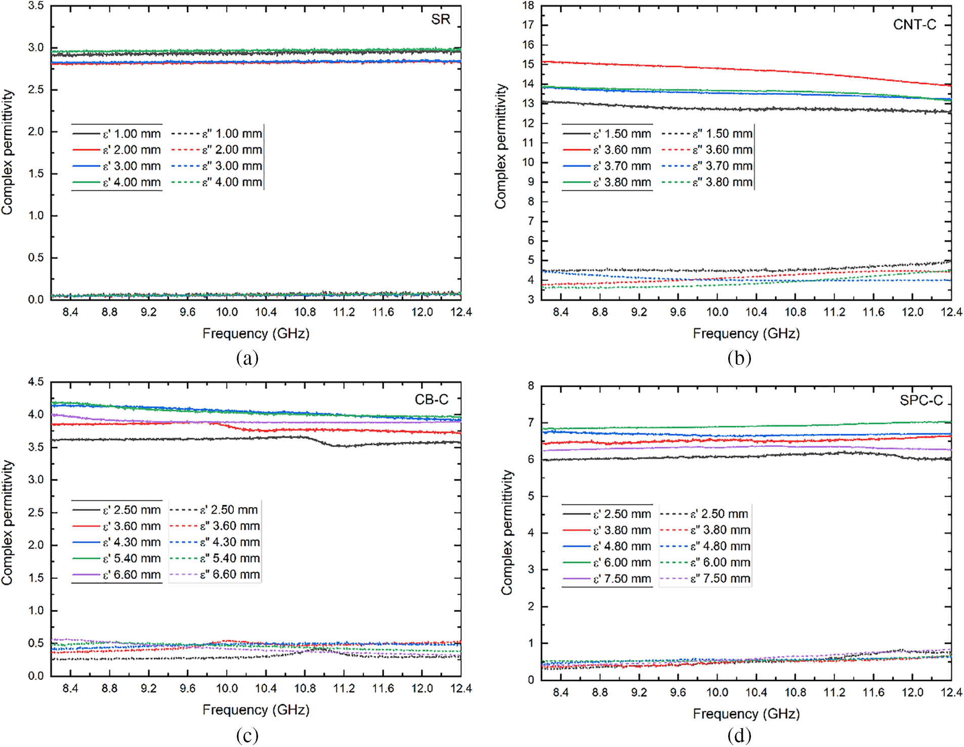
Figure A1: Individual complex permittivity of (a) silicone rubber, (b) carbon nanotube composite, (c) carbon black composite, and (d) sustainable porous carbon composite. These data were used to calculate the average permittivity in Fig. 7
Cite This Article
 Copyright © 2024 The Author(s). Published by Tech Science Press.
This work is licensed under a Creative Commons Attribution 4.0 International License , which permits unrestricted use, distribution, and reproduction in any medium, provided the original work is properly cited.
 Downloads
 Citation Tools