 Open Access
ARTICLE
Numerical Study on the Behaviour of Hybrid FRPs Reinforced RC Slabs Subjected to Blast Loads
1
College of Civil Engineering, Nanjing Forestry University, Nanjing, 210037, China
2
Joint International Research Laboratory for Bio-Composite Building Materials and Structures, Nanjing Forestry University,
Nanjing, 210037, China
3
Nantong Shirui Reinforced Plastic Products Co., Ltd., Nantong, 226002, China
4
University College London, London, WC1E 6BT, UK
5
Fiber Composite Laboratory, Hindustan Institute of Technology and Science, Chennai, 603103, India
6
Jiangsu Fiber Composite Co., Ltd., Yancheng, 224700, China
* Corresponding Authors: Mahdi Hosseini. Email: ; Haitao Li. Email:
Journal of Renewable Materials 2023, 11(9), 3517-3531. https://doi.org/10.32604/jrm.2023.028164
Received 08 December 2022; Accepted 29 December 2022; Issue published 20 July 2023
Abstract
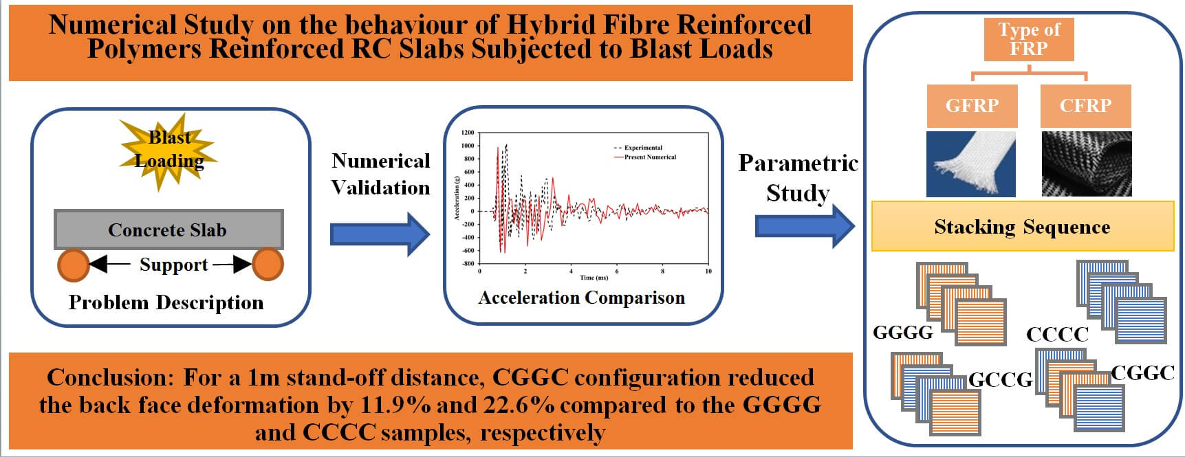
The safety of civilian and military infrastructure is a concern due to an increase in explosive risks, which has led to a demand for high-strength civil infrastructure with improved energy absorption capacity. In this study, a Finite Element (FE) numerical model was developed to determine the effect of hybrid Fibre Reinforced Polymer (FRP) as a strengthening material on full-scale Reinforced Concrete (RC) slabs. The reinforcing materials under consideration were Carbon (CFRP) and Glass (GFRP) fibres, which were subjected to blast loads to determine the structural response. A laminated composite fabric material model was utilized to model the failure of composite, which facilitates the consideration of strain rate effects. The damaged area of the laminate is determined in the FE model, and it is in good agreement with the corresponding experimental results in the literature. Models containing different stacking sequences were built to demonstrate their efficiency in resisting blast loads. In general, the damaged area was reduced when a hybrid reinforcement with CFRP as the top layer was used.Graphic Abstract
Keywords
During the 1987 Structures Congress, it was claimed that protecting structures against terrorist assaults was already regarded as an issue at the time [1]. Based on a recent survey, explosives are responsible for 50% of terrorist assaults, raising serious concerns about the protection of civilian and military infrastructure [2,3]. This has attracted a lot of attention to the susceptibility and longevity of civil and military structures and their specific structural parts when subjected to blast loads [4]. Because protection against explosion is not an absolute proposition, and an improved level of damage protection always comes at a significant cost, appropriate evaluation tools must be used to identify any solution with an acceptable level of accuracy.
Numerous studies have examined the possibility of civil infrastructure being damaged by blast loads and the improvement in blast resistance resulting from external reinforcements [5]. The typical FRP systems used are: Carbon, glass, aramid, and basalt fibres are bound together by a polymer matrix such as epoxy, vinyl ester, or polyester to make CFRP, GFRP, AFRP, and BFRP, respectively [6–10]. FRP and polyurea coatings are the most frequently preferred exterior reinforcements [11–14]. An experimental study on RC walls retrofitted with CFRP and GFRP under 860 kg of explosive TNT at close ranges discovered that the retrofitted walls exhibit greater blast load resistance [15]. Jacques [16] investigated the effect of using externally bonded fibre-reinforced polymers as a retrofit strategy to improve blast resistance in concrete walls and slabs. A significant increase in strength and stiffness was observed, while there was a significant reduction in maximum displacement in samples reinforced with FRP. Orton et al. [17] investigated the effect of close-in blast loads on CFRP reinforced with concrete slab samples. The testing findings revealed that the CFRP effectively resisted the blast load and reduced total slab deflections for a greater scaled value. Under high blast loads, the concrete failed catastrophically across the slab’s thickness, and complete rupture was visible at the CFRP’s back face for the lower scaled value. According to Corradi et al. [18], using unidirectional CFRP or GFRP on the masonry panels can significantly enhance the strength of damaged components of the structure. But the existing research on the investigation of reinforcing FRP with concrete infrastructures against blast loads focuses mostly on walls [19–21] or beams [22–25]. Thus, there is a need to study the effect of FRP reinforcement on concrete slabs under blast loading.
In order to determine the effect of FRP-strengthened RC structures when exposed to blast loads, numerous numerical approaches have been proposed. These numerical investigations show that sustaining the composite action between the FRP and concrete depends significantly on the bond strength and the number of layers. Using a numerical model, FRP-reinforced RC walls with anchoring subjected to blast loading were studied by Mutalib et al. [26]. The results revealed that FRP strengthening efficiently enhances the RC wall’s capacity to withstand blast loads. From the numerical simulation of concrete exposed to different strain rates under blast loading, Xu et al. [27] devised spallation criteria. They considered three-dimensional spallation criteria that account for the structural reaction to close-range explosive detonation. Elsanadedy et al. [28] investigated the impact of CFRP retrofitting RC circular columns under blast loading using LS-DYNA and discovered that the addition of CFRP layers increased the column’s capacity to withstand higher-intensity blasts. Using LS-DYNA and the Johnson-Holmquist model, Schenker et al. [29] investigated the effects of concrete strength ratio, slab thickness, and steel reinforcement ratio on RC slabs subjected to blast loading. Several experimental setups have investigated the characterization of composite materials under varied loading rates. According to investigations in the literature, FRP composites’ mechanical behavior can exhibit clear positive rate dependence, rate-insensitive behaviour, or negative rate dependence. Elanchezhian et al. [30] studied the effect of strain rate on the mechanical and flexural behaviour of CFRP and GFRP composite laminates and concluded that Although the strain to failure for both CFRP and GFRP dropped with increasing strain rate, the dynamic material strength for GFRP improved with higher strain rates. Shokrieh et al. [31] conducted compressive tests using unidirectional GFRP composites with strain rates ranging from 0.001 to 100 s. Compressive strength and modulus were observed to improve with increasing strain rates, but compressive strain to failure was found to be relatively insensitive to strain rates. However, due to the complexities of blast behaviour, the majority of these investigations generated only qualitative rather than quantitative conclusions. Furthermore, many studies did not take into account the strain rate effect of concrete and FRP, preventing a deeper understanding of the blast mechanism of resistance in FRP-strengthened civil structures. Over the past decade, extensive experimental research has been undertaken to develop unique methods to improve the deflection response and damage resistance of concrete slabs under blast loading [32–34]. Silva et al. [35] experimentally evaluated the viability of enhancing RC slabs’ blast resistance through novel composite materials. They concluded that slabs retrofitted with the novel steel FRP composite performed similarly to CFRP composite, resulting in a cost-effective system with better blast load-resisting capability. Wu et al. [36] experimentally investigated the blast resistances of slabs made with externally bonded FRP plates, and it was determined that adding carbon FRP plates to reinforce the concrete slab’s compression face enhanced the slab’s ductility and blast resistance. To determine the fragment size distribution and fragment shape factor distribution, Wu et al. [37] worked on RC slabs reinforced with CFRP plates installed on both sides of the slab and tested them with a 2.1 kg TNT blast load at a standoff distance of 0.6 m. Statistical analysis concluded that the fragment sizes and shapes for both the RC slabs followed the Weibull distribution and lognormal distribution, respectively.
While significant studies have been conducted on the blast load resistance of FRP-strengthened civil structures, meagre research has been done on the resistance of FRP-reinforced RC slabs. In the current study, we extend the efforts from Reifarth et al. [38] in the area of blast loading to fundamentally understand the concrete and composite blast load resistance mechanisms and the effect of reinforcing hybrid FRPs in RC slabs. With full-scale dimensions of the RC slab, a numerical modelling technique was used, and CFRP and GFRP were chosen as hybrid reinforcements. A 3D lagrangian model was developed and validated against the experimental results. Based on the confidence of the validated model, an extensive study was carried out to determine the failure mechanism of the composite under the blast load. Finally, the effect of the stacking sequence with material model considering strain rate effects was considered in the study for modelling the composite laminate.
The dynamic behaviour of concrete RC slabs reinforced with hybrid FRP subjected to blast load was investigated using the commercially available non-linear finite element tool LS-DYNA [39]. The numerical model was created and tested against experimental findings in order to comprehend the progression of damage and forecast the behaviour of the slab. To investigate the failure mechanism and damaged area, a material model with strain rate effect was taken into consideration.
The slabs without FRP reinforcement were used to validate the numerical model based on experimental results from Reifarth et al. [38]. Two layers of longitudinal and transverse bars made up the slab’s steel reinforcement, which was modelled using Hughes-Liu beam elements. One longitudinal bar was missing from each of the top and lower layers in the experimental model described in the literature due to a manufacturing error, and the numerical model used a similar arrangement as shown in Figs. 1 and 2. To connect the concrete slab to the steel rebar, four 20-mm-long constrained bars were used. The upper face of the concrete slab was supported with 10 mm bars placed 300 mm apart in both directions, while the bottom face was supported with 12 mm bars spaced 150 mm apart in both directions. The steel mesh was represented using the widely known PIECEWISE LINEAR_PLASTICITY material model [40–42], which defines an elastoplastic bilinear behaviour. The values for the material model are considered from the literature and are defined in Table 1. Finally, there are 7710 elements used to model all the longitudinal and transverse beams in the slab. The constrained bars were placed 400 mm apart from the centre and at a distance of 37.5 mm from the top and bottom, respectively.

Figure 1: Upper longitudinal and transverse steel bar configuration

Figure 2: Lower longitudinal and transverse steel bar configuration

2.2 Modelling of Concrete Slab
The numerical model consisted of concrete slabs with dimensions of 4.40 m × 1.46 m × 0.15 m made using 963600 solid elements with a mesh size of 10 mm. Based on the literature [43,44] the CSCM_Concrete material model was used to model the concrete slab. The CSCM model is an elastoplastic damage material model. The shear surface and cap are used to simulate the strength of concrete in the low-high confining pressure regimes. According to the literature, the CSCM material model is suitable for simulating concrete structures with compressive strengths ranging from 20 to 48 MPa. The CSCM model only requires two parameters to function: unconfined compressive strength and density, with the ERODE option for element deletion set to default. The material properties used in the simulation are defined in Table 2.

2.3 Modelling of External Reinforcements
MAT LAMINATED COMPOSITE FABRIC is used to model the woven FRP composite external reinforcement to the concrete slab. In the described material model, the composite damage is modelled based on Hasin’s failure theory which accounts for the non-linear softening of the composite plies [45]. Each composite ply is modelled using 64240 2D shell elements with fully integrated shell elements since it was determined to be the optimal method of modelling based on literature [46]. The failure criteria as defined in Eqs. (1) and (2) was considered to be the same in direction 1 and 2 since woven composite laminates are considered and a smooth failure surface condition (FS = 1) was defined in the model [47].
Notes:
Once the threshold stress is reached, the elements will be removed from the calculation. This is obtained using the ERODS option in the material model. The ERODS needs to be carefully calibrated to facilitate effective modelling of the composite. A value of −0.4 and −0.6 was determined to be suitable for CFRP and GFRP respectively in the simulation, which is in coherence with the data available in the literature [48–50]. The material properties used in the numerical simulation are defined in Table 3.

As illustrated in Fig. 3, four combinations were selected to represent the impact of the stacking sequence of the external reinforcements: (a) GGGG (b) CCCC (c) GCCG, and (d) CGGC. The hybrid laminate’s layer configuration was chosen by balancing the modulus property with regard neutral axis in the RC slab.
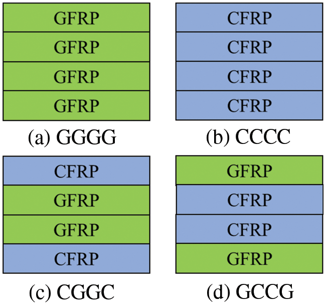
Figure 3: Four combinations of the stacking sequence of the external reinforcements: (a) GGGG (b) CCCC (c) GCCG, and (d) CGGC
The simulation uses a surface-to-surface tiebreak contact algorithm based on normal and shear strengths of interlaminar properties. The nodal tension is tracked and incorporated into the interface strength-based failure criterion expressed as Eq. (3)
Notes:
A lagrangian approach (CONWEP) was followed to model the blast loading using the LOAD_BLAST option. This method uses the empirical model to compute the blast load at an efficient computational time. Under high explosive detonation, blast wave propagates in the surrounding atmosphere. Generally, Friedlander formulation Eq. (4) is utilised to characterize the initial positive phase of the blast load.
where
The experimental results from the literature were utilised to determine the pressure [51]. The explosive of 1.74 kg was placed at a 1 m distance from the cement slab centre. The calculated equivalent peak pressure was 0.87 for TNT [52].
2.5 Contact and Constrained Conditions
Since the steel rebar and the concrete were modelled explicitly, CONSTRAINED_LAGRANGE_IN_SOLID was defined to model the interaction between the two components. The support rods at the boundary were constrained in the 6 DOFs for better accuracy. The roller supports were assigned AUTOMATIC_SINGLE_SURFACE contact against the concrete slab. For external reinforcement modelling, AUTOMATIC_ONE_WAY_SURFACE_TO_SURFACE_TIEBREAK contact was defined between each layer in the composite and in between concrete and composite in the model. To model the interaction between the blast and the interacting surface, the SET_SEGMENT option was utilised to define the face of the interacting surface.
3.1 Validation Study Based on Peak Acceleration
Reifarth et al. [38] used the experimental data to evaluate the proposed numerical model against the concrete slab without external reinforcement. In the experimental investigation, the acceleration was measured 100 mm from the centre of the cement slab, and a comparable dimension was used in the numerical simulation to calculate the peak acceleration due to blast load. The peak acceleration obtained from the simulation was about 979.1 g, whereas the experimentally reported peak acceleration was about 1028.6 g, as shown in Fig. 4. A deviation of 4.81% is observed between the experimental and numerical results. Generally, any variation less than 10% between experimental and numerical results is considered acceptable. Thus, the proposed numerical modelling method is acceptable and can be considered for further study.
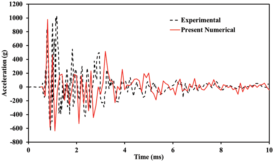
Figure 4: Experimental and numerical comparison of Z-acceleration time history
3.2 Validation Study Based on Effective Strain
The anticipated area of eroded elements and the area of those elements whose cumulative damage is near to 1 on a scale of 0 to 1 are added together to calculate the damaged area in the numerical models, which are shown from blue to red. Fig. 5 represents the effective strain for the RC slab. In both the experimental specimens and the computational models, the RC slab shows no structural damage other than controlled flexural cracking. However, there can be seen some strain concentrations observed at the boundary of the RC slab, and they are due to the roller support at the base of the slab. Thus, it can be concluded that the numerical model can reproduce the damaged contour effectively compared to the experimental results.

Figure 5: Back face deformation of the RC slab
3.3 Validation Study Based on Damaged Area
Two samples, designated P1 and P2, were examined based on the damaged area. 13.05 kg of TNT were exposed to samples P1 and P2 at standoff distances of 0.5 and 1 m, respectively. The slabs were studied to provide a benchmark to compare the damage to that of the externally reinforced ones and enable the study of the effects of scaled distance. Table 4 compares the damaged area as a percentage of the overall surface area. The literature has used a similar method to compare the numerical and experimental results [53]. Because the material model is properly calibrated with supporting parameters, the current numerical simulation actually yields better findings when compared to published results. Although the top face area calculation represents a variation of 16.27%, the damage mechanism reliably predicts the fracture and cracks in the RC slab under the blast load condition.

3.4 Effect of Plane CFRP and GFRP as External Reinforcement
The numerical results corresponding to plane CFRP and GFRP reinforced slabs with a standoff distance of 0.5 and 1 m are shown in Fig. 6, respectively. The numerical model is capable of capturing the geometry of the failure surface. The damage pattern exhibited by both configurations at respective standoff distances were similar. Circumferential cracking was evident in both samples where the crack protruded in the sheet mesh directions. In the sample CCCC, the intensity of cracks was relatively lower when compared to GGGG samples. The back face damage for the CCCC sample was 20% less when compared to GGGG samples. In the case of blast load at a standoff distance of 1 m, the damage was significantly reduced when compared to unreinforced samples. Thus it can be concluded that the contribution of FRP is evident when the structure is subjected to blast loads.
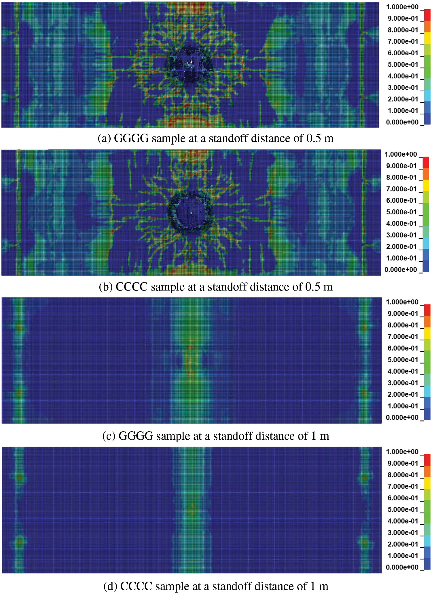
Figure 6: Plastic strain contour for different reinforcements
3.5 Effect of CGGC and GCCG Stacking Sequence
Two different stacking sequences, (a) CGGC and (b) GCCG, were preferred in the study to determine the effect of stacking sequence as shown in Fig. 7. The hybrid laminates were selected considering balanced material properties in the longitudinal and transverse directions. The CGGC configuration presented lower damage when compared to the GCCG configuration. This indicates that the CGGC configuration performed better in terms of blast load resistance, which is consistent with the literature [54,55]. The failure between external reinforcement and the concrete slab was considered to be a perfect bond. Thus, the failure pattern between the laminate and composite was not captured efficiently. On comparing the relative damage region, the CGGC configuration reduced the back face deformation by 3.4% and 24.3% compared to the CCCC and GGGG samples, respectively. The damage pattern due to 13.05 kg TNT at a 0.5 m standoff distance appeared to be similar for both configurations, with the GCCG sample dominating the damaged region. In the case of CGGC samples, the circumferential cracks propagated a longer distance with a comparatively lower central puncture when compared to the GCCG sample. When the standoff distance was 1 m, both the samples showed better resistance with a central longitudinal deformation.
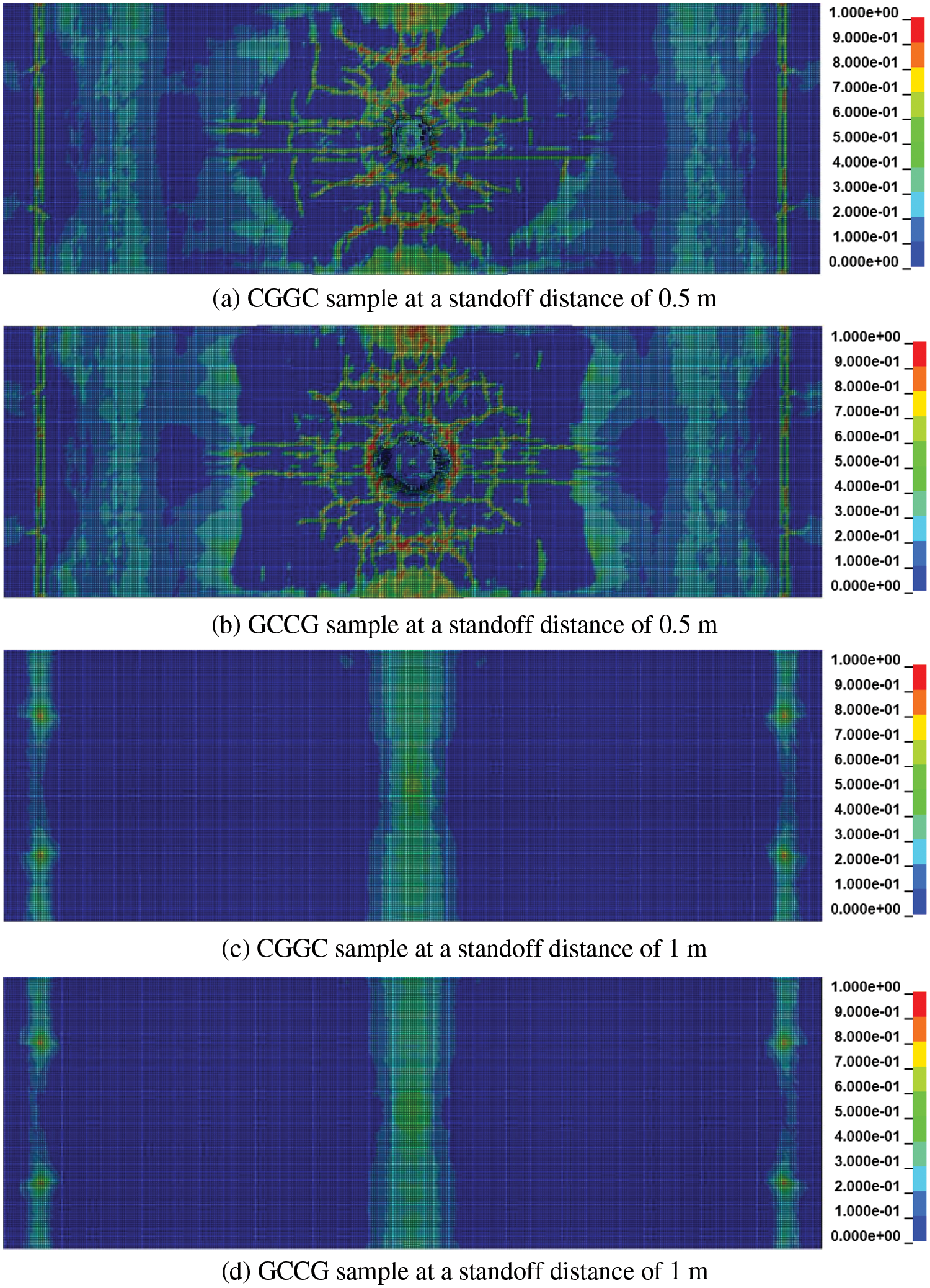
Figure 7: Stacking sequence effect on plastic strain contour
3.6 Effect of Stacking Sequence
At various standoff distances, the effect of glass/carbon hybrid laminates as reinforcement to RC slabs is investigated. The resulting relative damage is illustrated in Table 5. When plane and hybrid laminate layouts were compared, it was clear that hybrid laminate provided greater blast load resistance for both standoff distances. The CGGC configuration outperformed the GCCG configuration. Studies from the literature state that laminates with solely CFRP layers may not provide suitable reinforcement under different types of load when compared to hybrid combinations [56]. Though carbon fibres have a larger elastic modulus than glass fibres, the resulting performance of CFRP laminates is relatively weaker as they suffer from brittle damage when compared to GFRP laminates. As a result, it may be stated that a hybrid arrangement consisting of glass fibres sandwiched between carbon fibres will give superior resistance to blast load than any other possible external reinforcement. The resulting relative damage is illustrated in Fig. 8.

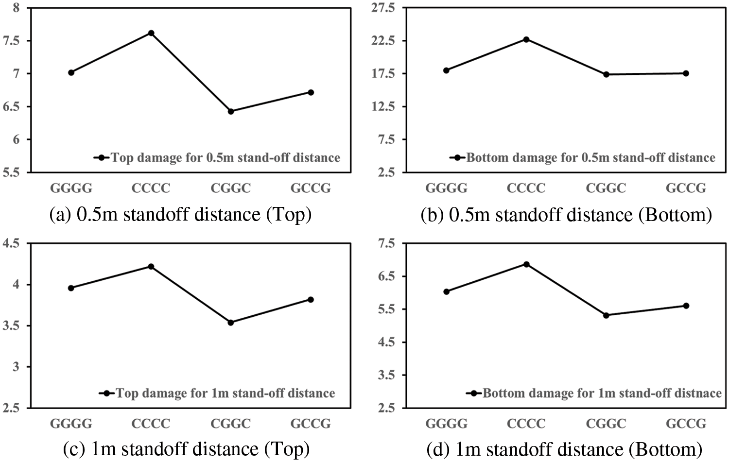
Figure 8: The comparison of relative damage based on the stacking sequence
In order to assess the positive impact of CFRP and GFRP reinforcement on RC slabs subjected to blast load scenarios with distinct scaled distances, a numerical investigation was conducted. The numerical simulation was validated against experimental results from the literature and the deviation in results was determined to be within acceptable limits. The specific observations are:
• In the case of the validation study, the peak acceleration obtained from the simulation was about 979.1 g, whereas the experimentally reported peak acceleration was about 1028.6 g. There were greater deviations in predicting the acceleration pattern beyond 1 ms, but the magnitude of secondary acceleration was captured effectively.
• The failure mechanism was captured well for all the studied cases and was used to optimize the external reinforcement configuration for a given standoff distance.
• For a 1 m standoff distance, CGGC configuration reduced the back face deformation by 11.9% and 22.6% compared to the GGGG and CCCC samples.
• When it comes to hybrid composite laminate configurations, placing carbon fibre layers on the outside and glass layers on the inside provides superior reinforcement than placing glass layers on the outside and carbon layers on the inside.
Acknowledgement: The writers gratefully acknowledge Ben Chen, Zhen Wang, Han Zhang, Ke Zhou, Xiaoyan Zheng, Shaoyun Zhu, Liqing Liu, Dunben Sun, Jing Cao, Yanjun Liu, Junhong Xu and others from the Nanjing Forestry University for helping.
Funding Statement: The research work presented in this paper is supported by the Foreign Young Talents Project China (No. QN2021014006L), National Natural Science Foundation of China (Nos. 51878354 & 51308301), the Natural Science Foundation of Jiangsu Province (Nos. BK20181402 & BK20130978), 333 Talent High-Level Projects of Jiangsu Province and Qinglan Project of Jiangsu Higher Education Institutions. Any research results expressed in this paper are those of the writers and do not necessarily reflect the views of the foundations.
Conflicts of Interest: The authors declare that they have no conflicts of interest to report regarding the present study.
References
1. Longinow, A., Krauthammer, T., Mohammadi, J. (2001). Research needs to resist terrorist attacks in dynamics of structures. USA: American Society of Civil Engineering (ASCE). [Google Scholar]
2. Chipley, M., Lyon, W., Smilowitz, R., Williams, P., Arnold, C. et al. (2012). Primer to design safe school projects in case of terrorist attacks and school shootings, buildings and infrastructure protection series. Washington: U.S. Department of Homeland Security. [Google Scholar]
3. Dobbs, N., Baker, W., Thomas, Z. (1990). Army TM5-1300 structures to resist the effects if accidental explosions. Washington: U.S. Department of the Army. [Google Scholar]
4. Morrill, K. B., Malvar, L. J., Crawford, J. E., Hegemier, G., Seible, F. (2001). Full-scale testing of reinforced concrete column retrofits to resist blast loads. Proceedings of the Tenth International Symposium on Interaction of the Effects of Munitions with Structures, Miramar Beach, USA. https://doi.org/10.1061/(ASCE)0893-1321(2008)21:4(217) [Google Scholar] [CrossRef]
5. Mosalam, K. M., Mosallam, A. S. (2001). Nonlinear transient analysis of reinforced concrete slabs subjected to blast loading and retrofitted with CFRP composites. Composites Part B: Engineering, 32(8), 623–636. https://doi.org/10.1016/S1359-8368(01)00044-0 [Google Scholar] [CrossRef]
6. Mohamed, T., Elshazli, N. S., Ahmed, I. (2022). Structural response of high strength concrete beams using fiber reinforced polymers under reversed cyclic loading. Sustainable Structures, 2(2), 000018. https://doi.org/10.54113/j.sust.2022.000018 [Google Scholar] [CrossRef]
7. Liang, R., Hota, G. (2021). Development and evaluation of load-bearing fiber reinforced polymer composite panel systems with tongue and groove joints. Sustainable Structures, 1(2), 000008. https://doi.org/10.54113/j.sust.2021.000008 [Google Scholar] [CrossRef]
8. Olonisakin, K., He, S. P., Yang, Y. F., Wang, H. P., Li, R. et al. (2022). Influence of stacking sequence on mechanical properties and moisture absorption of epoxy-based woven flax and basalt fabric hybrid composites. Sustainable Structures, 2(2), 000016. https://doi.org/10.54113/j.sust.2022.000016 [Google Scholar] [CrossRef]
9. Hosseini, M., Jian, B., Li, H., Yang, D., Wang, Z. et al. (2022). A review of fibre reinforced polymer (FRP) reinforced concrete composite column members modelling and analysis techniques. Journal of Renewable Materials, 10(12), 3244–3262. https://doi.org/10.32604/jrm.2022.022171 [Google Scholar] [CrossRef]
10. Wilt, J., GangaRao, H., Liang, R. F., Mostoller, J. (2023). Structural responses of FRP sheet piles under cantilever loading. Sustainable Structures, 3(1), 000021. https://doi.org/10.54113/j.sust.2023.000021 [Google Scholar] [CrossRef]
11. Dong, Z., Jia, J., Liu, Z., Wu, C., Wua, G. et al. (2023). I-shaped ECC/UHPC composite beams reinforced with steel bars and BFRP sheets. Sustainable Structures, 3(1), 000022. https://doi.org/10.54113/j.sust.2023.000022 [Google Scholar] [CrossRef]
12. Yan, J., Liu, Y., Xu, Z., Li, Z., Huang, F. (2020). Experimental and numerical analysis of CFRP strengthened RC columns subjected to close-in blast loading. International Journal of Impact Engineering, 146, 103720. https://doi.org/10.1016/j.ijimpeng.2020.103720 [Google Scholar] [CrossRef]
13. Chen, Y. S., Wang, B., Zhang, B., Zheng, Q., Zhou, J. N. et al. (2020). Polyurea coating for foamed concrete panel: An efficient way to resist explosion. Defence Technology, 16(1), 136–149. https://doi.org/10.1016/j.dt.2019.06.010 [Google Scholar] [CrossRef]
14. Li, H., Chen, B., Fei, B., Li, H., Xiong, Z. et al. (2022). Mechanical properties of aramid fiber reinforced polymer confined laminated bamboo lumber column under cyclic loading. European Journal of Wood and Wood Products, 80, 1057–1070. https://doi.org/10.1007/s00107-022-01816-4 [Google Scholar] [CrossRef]
15. Muszynski, L. C., Purcell, M. R. (2003). Composite reinforcement to strengthen existing concrete structures against air blast. Journal of Composites for Construction, 7(2), 93–97. https://doi.org/10.1061/(ASCE)1090-0268(2003)7:2(93) [Google Scholar] [CrossRef]
16. Jacques, E. (2011). Blast retrofit of reinforced concrete walls and slabs. Canada: University of Ottawa. [Google Scholar]
17. Orton, S. L., Chiarito, V. P., Minor, J. K., Coleman, T. G. (2014). Experimental testing of CFRP-strengthened reinforced concrete slab elements loaded by close-in blast. Journal of Structural Engineering, 140(2), 04013060. https://doi.org/10.1061/(ASCE)ST.1943-541X.0000821 [Google Scholar] [CrossRef]
18. Corradi, M., Borri, A., Vignoli, A. (2002). Strengthening techniques tested on masonry structures struck by the Umbria–Marche earthquake of 1997–1998. Construction and Building Materials, 16(4), 229–239. https://doi.org/10.1016/S0950-0618(02)00014-4 [Google Scholar] [CrossRef]
19. Yavartanoo, F., Kang, T. H. K. (2022). Retrofitting of unreinforced masonry structures and considerations for heritage-sensitive constructions. Journal of Building Engineering, 49, 103993. https://doi.org/10.1016/j.jobe.2022.103993 [Google Scholar] [CrossRef]
20. Zhou, D., Lei, Z., Wang, J. (2013). In-plane behavior of seismically damaged masonry walls repaired with external BFRP. Composite Structures, 102, 9–19. https://doi.org/10.1016/j.compstruct.2013.01.031 [Google Scholar] [CrossRef]
21. Tabatabaei, Z. S., Volz, J. S., Baird, J., Gliha, B. P., Keener, D. I. (2013). Experimental and numerical analyses of long carbon fiber reinforced concrete panels exposed to blast loading. International Journal of Impact Engineering, 57, 70–80. https://doi.org/10.1016/j.ijimpeng.2013.01.006 [Google Scholar] [CrossRef]
22. Tetta, Z. C., Koutas, L. N., Bournas, D. A. (2015). Textile-reinforced mortar (TRM) versus fiber-reinforced polymers (FRP) in shear strengthening of concrete beams. Composites Part B: Engineering, 77, 338–348. https://doi.org/10.1016/j.compositesb.2015.03.055 [Google Scholar] [CrossRef]
23. Aksoylu, C., Yazman, Ş., Özkılıç, Y. O., Gemi, L., Arslan, M. H. (2020). Experimental analysis of reinforced concrete shear deficient beams with circular web openings strengthened by CFRP composite. Composite Structures, 249, 112561. https://doi.org/10.1016/j.compstruct.2020.112561 [Google Scholar] [CrossRef]
24. Moradi, E., Naderpour, H., Kheyroddin, A. (2020). An experimental approach for shear strengthening of RC beams using a proposed technique by embedded through-section FRP sheets. Composite Structures, 238, 111988. https://doi.org/10.1016/j.compstruct.2020.111988 [Google Scholar] [CrossRef]
25. Gemi, L., Madenci, E., Özkılıç, Y. O., Yazman, Ş., Safonov, A. (2022). Effect of fiber wrapping on bending behavior of reinforced concrete filled pultruded GFRP composite hybrid beams. Polymers, 14(18), 3740. https://doi.org/10.3390/polym14183740 [Google Scholar] [PubMed] [CrossRef]
26. Mutalib, A. A., Hao, H. (2011). Numerical analysis of FRP-composite-strengthened RC panels with anchorages against blast loads. Journal of Performance of Constructed Facilities, 25(5), 360–372. https://doi.org/10.1061/(ASCE)CF.1943-5509.0000199 [Google Scholar] [CrossRef]
27. Xu, K., Lu, Y. (2006). Numerical simulation study of spallation in reinforced concrete plates subjected to blast loading. Computers & Structures, 84(5–6), 431–438. https://doi.org/10.1016/j.compstruc.2005.09.029 [Google Scholar] [CrossRef]
28. Elsanadedy, H. M., Almusallam, T. H., Abbas, H. U. S. A. I. N., Al-Salloum, Y. A., Alsayed, S. H. (2011). Effect of blast loading on CFRP-retrofitted RC columns-A numerical study. Latin American Journal of Solids and Structures, 8, 55–81. https://doi.org/10.1590/S1679-78252011000100004 [Google Scholar] [CrossRef]
29. Schenker, A., Anteby, I., Gal, E., Kivity, Y., Nizri, E. et al. (2008). Full-scale field tests of concrete slabs subjected to blast loads. International Journal of Impact Engineering, 35, 184–198. https://doi.org/10.1016/j.ijimpeng.2006.12.008 [Google Scholar] [CrossRef]
30. Elanchezhian, C., Ramnath, B. V., Hemalatha, J. (2014). Mechanical behaviour of glass and carbon fibre reinforced composites at varying strain rates and temperatures. Procedia Materials Science, 6, 1405–1418. https://doi.org/10.1016/j.mspro.2014.07.120 [Google Scholar] [CrossRef]
31. Shokrieh, M. M., Omidi, M. J. (2009). Compressive response of glass–fiber reinforced polymeric composites to increasing compressive strain rates. Composite Structures, 89, 517–523. https://doi.org/10.1016/j.compstruct.2008.11.006 [Google Scholar] [CrossRef]
32. Morales-Alonso, G., Cendón, D. A., Gálvez, F., Erice, B., Sánchez-Gálvez, V. (2011). Blast response analysis of reinforced concrete slabs: Experimental procedure and numerical simulation. Journal of Applied Mechanics, 78. https://doi.org/10.1115/1.4004278 [Google Scholar] [CrossRef]
33. Wang, W., Zhang, D., Lu, F., Wang, S., Tang, F. (2013). Experimental study and numerical simulation of the damage mode of a square reinforced concrete slab under close-in explosion. Engineering Failure Analysis, 27, 41–51. https://doi.org/10.1016/j.engfailanal.2012.07.010 [Google Scholar] [CrossRef]
34. Thiagarajan, G., Kadambi, A. V., Robert, S., Johnson, C. F. (2015). Experimental and finite element analysis of doubly reinforced concrete slabs subjected to blast loads. International Journal of Impact Engineering, 75, 162–173. https://doi.org/10.1016/j.ijimpeng.2014.07.018 [Google Scholar] [CrossRef]
35. Silva, P. F., Lu, B. (2007). Improving the blast resistance capacity of RC slabs with innovative composite materials. Composites Part B: Engineering, 38, 523–534. https://doi.org/10.1016/j.compositesb.2006.06.015 [Google Scholar] [CrossRef]
36. Wu, C., Oehlers, D. J., Rebentrost, M., Leach, J., Whittaker, A. S. (2009). Blast testing of ultra-high performance fibre and FRP-retrofitted concrete slabs. Engineering Structures, 31, 2060–2069. https://doi.org/10.1016/j.engstruct.2009.03.020 [Google Scholar] [CrossRef]
37. Wu, C., Nurwidayati, R., Oehlers, D. J. (2009). Fragmentation from spallation of RC slabs due to airblast loads. International Journal of Impact Engineering, 36, 1371–1376. https://doi.org/10.1016/j.ijimpeng.2009.03.014 [Google Scholar] [CrossRef]
38. Reifarth, C., Castedo, R., Santos, A. P., Chiquito, M., López, L. M. et al. (2021). Numerical and experimental study of externally reinforced RC slabs using FRPs subjected to close-in blast loads. International Journal of Impact Engineering, 156, 103939. https://doi.org/10.1016/j.ijimpeng.2021.103939 [Google Scholar] [CrossRef]
39. Livermore Software Technology Corporation. Version 971 keyword user’s manual 2007. [Google Scholar]
40. Elsanadedy, H. M., Almusallam, T. H., Alsayed, S. H., Al-salloum, Y. A. (2015). Experimental and FE study on RC one-way slabs upgraded with FRP composites. KSCE Journal of Civil Engineering, 19(4), 1024–1040. https://doi.org/10.1007/s12205-013-0689-y [Google Scholar] [CrossRef]
41. Mkrtychev, O., Sidorov, D., Bulushev, S. (2017). Comparative analysis of results from experimental and numerical studies on concrete strength. MATEC Web of Conferences, 117, 00123. https://doi.org/10.1051/matecconf/201711700123 [Google Scholar] [CrossRef]
42. Mkrtychev, O., Andreev, M. (2018). Verification of the reinforced concrete beam model based on the results of a full-scale experimental study. MATEC Web of Conferences, 196, 01029. https://doi.org/10.1051/matecconf/201819601029 [Google Scholar] [CrossRef]
43. Ruggiero, A., Bonora, N., Curiale, G., de Muro, S., Iannitti, G. et al. (2019). Full scale experimental tests and numerical model validation of reinforced concrete slab subjected to direct contact explosion. International Journal of Impact Engineering, 132, 103309. https://doi.org/10.1016/j.ijimpeng.2019.05.023 [Google Scholar] [CrossRef]
44. Gomathi, K. A., Rajagopal, A., Reddy, K. S. S., Ramakrishna, B. (2020). Plasticity based material model for concrete subjected to dynamic loadings. International Journal of Impact Engineering, 142, 103581. https://doi.org/10.1016/j.ijimpeng.2020.103581 [Google Scholar] [CrossRef]
45. Matzenmiller, A., Lubliner, J., Taylor, R. L. (1995). A constitutive model for anisotropic damage in fiber-composites. Mechanics of Materials, 20, 125–152. https://doi.org/10.1016/0167-6636(94)00053-0 [Google Scholar] [CrossRef]
46. Heimbs, S., Heller, S., Middendorf, P., Hähnel, F., Weiße, J. (2009). Low velocity impact on CFRP plates with compressive preload: Test and modelling. International Journal of Impact Engineering, 36, 1182–1193. https://doi.org/10.1016/j.ijimpeng.2009.04.006 [Google Scholar] [CrossRef]
47. Scazzosi, R., Manes, A., Giglio, M. (2019). An enhanced material model for the simulation of high-velocity impact on fiber-reinforced composites. Procedia Structural Integrity, 24, 53–65. https://doi.org/10.1016/j.prostr.2020.02.005 [Google Scholar] [CrossRef]
48. Fasanella, E. L., Jackson, K. E., Lyle, K. H., Jones, L. E., Hardy, R. C. et al. (2008). Dynamic impact tolerance of space shuttle orbiter wing leading-edge panels. Journal of Spacecraft and Rockets, 45, 1042–52. https://doi.org/10.2514/1.31373 [Google Scholar] [CrossRef]
49. Bisagni, C., Giavotto, V. (2009). Experiments and analyses on post buckling behavior of stringer-stiffened laminated composite helicopter tailplane. Journal of the American Helicopter Society, 54, 0220031–02200312. https://doi.org/10.2514/6.2005-1866 [Google Scholar] [CrossRef]
50. Cherniaev, A., Montesano, J., Butcher, C. (2018). Modeling the axial crush response of CFRP tubes using MAT 054, MAT058 and MAT262 in LS-DYNA. 15th International LS-DYNA Users Conference, pp. 1–17. Detroit. [Google Scholar]
51. Kingery, C. N., Bulmash, G. (1984). Airblast parameters from tnt spherical air burst and hemispherical surface burst. USA Army Armament and Development Center, Ballistic Research Laboratory. [Google Scholar]
52. James, C. D. P. E., Joseph, E. G. P. E., Paul, A. P., Mcandrew, M., Bowling, C. (2008). Structures to resist the effects of accidental explosions. USA: U.S. Army Corps of Engineers. [Google Scholar]
53. Castedo, R., Segarra, P., Alañon, A., Lopez, L. M., Santos, A. P. et al. (2015). Air blast resistance of full-scale slabs with different compositions: Numerical modeling and field validation. International Journal of Impact Engineering, 86, 145–156. https://doi.org/10.1016/j.ijimpeng.2015.08.004 [Google Scholar] [CrossRef]
54. Pandya, K. S., Veerraju, C., Naik, N. K. (2011). Hybrid composites made of carbon and glass woven fabrics under quasi-static loading. Materials & Design, 32, 4094–4099. https://doi.org/10.1016/j.matdes.2011.03.003 [Google Scholar] [CrossRef]
55. Kretsis, G. (1987). A review of the tensile, compressive, flexural and shear properties of hybrid fibre-reinforced plastics. Composites, 18, 13–23. https://doi.org/10.1016/0010-4361(87)90003-6 [Google Scholar] [CrossRef]
56. Arora, H. (2012). Blast loading of fibre reinforced polymer composite structures (Doctoral Dissertation). Imperial College London, London. [Google Scholar]
Cite This Article
 Copyright © 2023 The Author(s). Published by Tech Science Press.
This work is licensed under a Creative Commons Attribution 4.0 International License , which permits unrestricted use, distribution, and reproduction in any medium, provided the original work is properly cited.


 Submit a Paper
 Propose a Special lssue
 View Full Text
 Download PDF
 Downloads
 Citation Tools