
 Submit a Paper
 Propose a Special lssue
 Open Access
ARTICLE

Experimental Study of Moso Bamboo to-Steel Connections with Embedded Grouting Materials
1 School of Civil Engineering, Chongqing University, Chongqing, 400045, China
2 Key Laboratory of New Technology for Construction of Cities in Mountain Area (Chongqing University), Ministry of Education, Chongqing, 400045, China
3 Suzhou Newcity Investment and Development Co., Ltd., Suzhou, China
4 Hangzhou Bangbo Technology Co., Ltd., Hangzhou, China
* Corresponding Author: Hui Wang. Email:
Journal of Renewable Materials 2023, 11(3), 1401-1423. https://doi.org/10.32604/jrm.2022.023446
Received 26 April 2022; Accepted 31 May 2022; Issue published 31 October 2022
 View Full Text
 Download PDF
Abstract
Moso bamboos have attracted excessive attention as a renewable green building material to the concept of sustainable development. In this paper, the 20 bolted Moso bamboo connection specimens with embedded steel plates and grouting materials were designed according to connection configurations with different bolt diameters and end distance of bolt holes, and their bearing capacities and failure modes were analyzed by static tension tests. According to the test results of all connectors, the failure modes of the specimens are divided into four categories, and the effects of bolt diameter and bolt hole end distance on the connection bearing capacity and failure mode are analyzed. The test results show that the deformation and failure process can be divided into four stages. The main influence factor of connector bearing capacity is bolt diameter. Connectors can be divided into four failure modes, and brittle failure can be avoided by adopting certain structural measures. Filling with grouting material can improve the bearing capacity of joints. Due to the large variability of bamboo, further experiments are needed.Keywords
There is a growing consensus on the applications of green building materials and the development of green buildings with the increasingly prominent problems of environmental pollution and energy consumption. Similar to wood [1,2], bamboo, a green building material with excellent mechanical properties, has attracted extensive attention in the field of structural engineering. As compared to traditional woods that needs to grow for several decades [3], the bamboos can grow up by 7.5~100 cm per day during the growing period [4], and it usually takes 3~6 years to grow into construction materials [5], which has a short growing cycle and is renewable. Compared with wood, bamboos have a higher cellulose content. The unique biological structure enables them to have high strength in the grain direction, thus the tensile strength can reach 70 Mpa [5], and the compressive strength can reach 190 MPa [6]. In comparison with traditional building materials, bamboo has a higher specific strength [7] and a higher application prospect in Southeast Asia [8,9]. As a special building material, many scholars have favored bamboo materials, and the mechanical properties under different connection structures were studied.
Hong et al. [10] introduced a variety of bamboo building connection joints at home and abroad and their research progress. Cui et al. [11] deeply understood the relationship between bamboo morphology and mechanics based on the finite element model. Tang et al. [12] studied the mechanical properties of bolted connections using laminated bamboo and steel plates, and single-bolt connections test results showed that the bearing capacity of the specimen increased linearly with the bolt diameter. Carrasco et al. [13] studied the influence of roughness on shear strength and the sliding module in the glued bond. It showed the surface treatment of the laminas by sanding should be used judiciously can achieve high strength and low deformability. The research of Zhang et al. [14] showed that nods would increase the compressive strength of Moso laminated bamboo lumber, but would have an adverse impact on the tensile strength.
As shown in Fig. 1, Villegas et al. [15] used steel hoop, U-shaped steel splint and bolts to realize the multi-angle connection between the chords and girders in the bamboo truss structure, and tested the bearing capacity of the bamboo truss under this connection mode through static tension tests. Huang et al. [16] showed the construction of grouting butt joints of bamboo tubes by adding a semi-perforated steel plate inside, pasting a CFRP sheet on the external wall and increasing the width of the steel plate is simple and efficient. Wang et al. [17] proposed dowel-type bamboo joints for prefabricated bamboo structures. The finite element model was established to verify the test results, and extensive parametric studies were carried out based on the simulation approach. Meanwhile, analytical models for designing the dowelled joints were proposed. Sonar et al. [18] proposed a bamboo splint connection in which bamboo pieces were placed between two steel plates and were fixed using bolts to study on mechanical properties of bamboo splint under different influence factors during axial tension. However, their tests only used bamboo pieces instead of complete bamboo tubes, therefore it is not entirely applicable to practical engineering. Fu et al. [19] proposed a configuration of sleeve-cement bamboo joint and carried out the tensile and compressive test on it. The tests showed that this connection has a good ductility under tension and high strength under compression, and can transfer axial loads in the bamboo joint effectively. Moran et al. [20–22] proposed three types of bamboo connections that can transfer bending moments. The steel hoops were used to reinforce bamboos to ensure their stability. Steel clamps facilitate joint assemblage and offer enough confinement to avoid premature splitting failures. Paraskeva et al. [23] fixed the steel plates between two bamboos by bolts, based on which this connection was reinforced with steel hoop and grouting materials. The results showed that the grouting materials could significantly improve the connection strength.
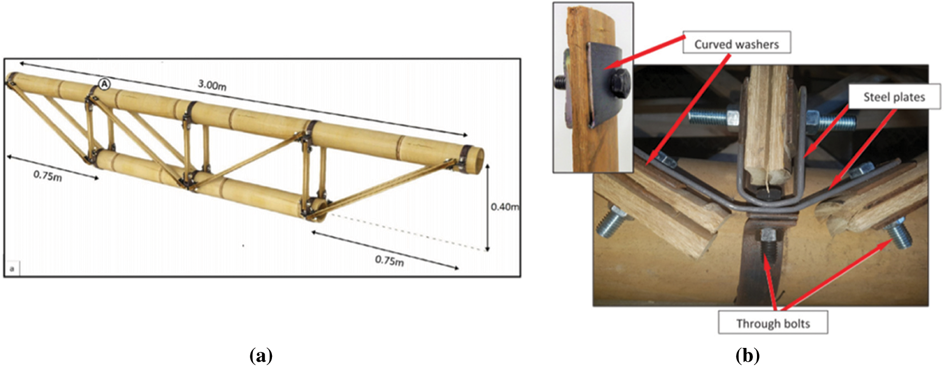
Figure 1: Schematic diagram of bamboo truss connection [15] (a) Geometrical configuration for the truss, (b) Connection details
The whole stability of the building structure depends on the robustness of connection in bamboo structures. As a key part of load-bearing and force transmission of the structure, the column base needs to ensure that the joint has sufficient strength and stiffness to bear various loads. Inspired by the steel plate concrete composite column and the anchor bar at the column base, this paper proposed a bolted Moso bamboo connection with embedded steel plates and grouting materials. The steel plate is placed in the bamboo tube, and the steel plate is connected through the screw after opening. At the same time, the bamboo tube at the column base is filled with high-strength mortar, so that the connection is more close and the strength is higher. By changing the end distances of bolt holes and bolt diameters in the whole designed connections, the tensile properties of this steel-to-bamboo connection were experimentally and analytically investigated, the effects of them on failure modes and bearing capacities of these connections were discussed, and reasonable design suggestions for connections are given.
2.1 Material Properties of Moso Bamboos
Moso bamboos used in the current study were extracted from the entire Moso bamboos in Anji Zhejiang, China. Their age is usually 5–6 years, and their moisture content is controlled at 12% ± 3%. Compared with the mechanical performance of traditional construction materials (such as concrete or steel), there is a variable (or coefficients of variation as referred to as COVs) of biological material mechanical properties. Therefore, when carrying out the material property test, the minimum number of required test pieces shall meet the maximum COVs. Moso bamboo materials specimens were made according to the Chinese industry standard JG/T 199–2007 [24]. Material properties tests include tensile test, compression test, shear strength test in the longitudinal texture direction and moisture content measurement. Typical material tests are shown in Fig. 2, respectively. In order to avoid the influence of material properties variability, 40 standard specimens were set for each group. Different test results are shown in Table 1, among which the COVs of three intensities are lower than 18%, which meets the specification.
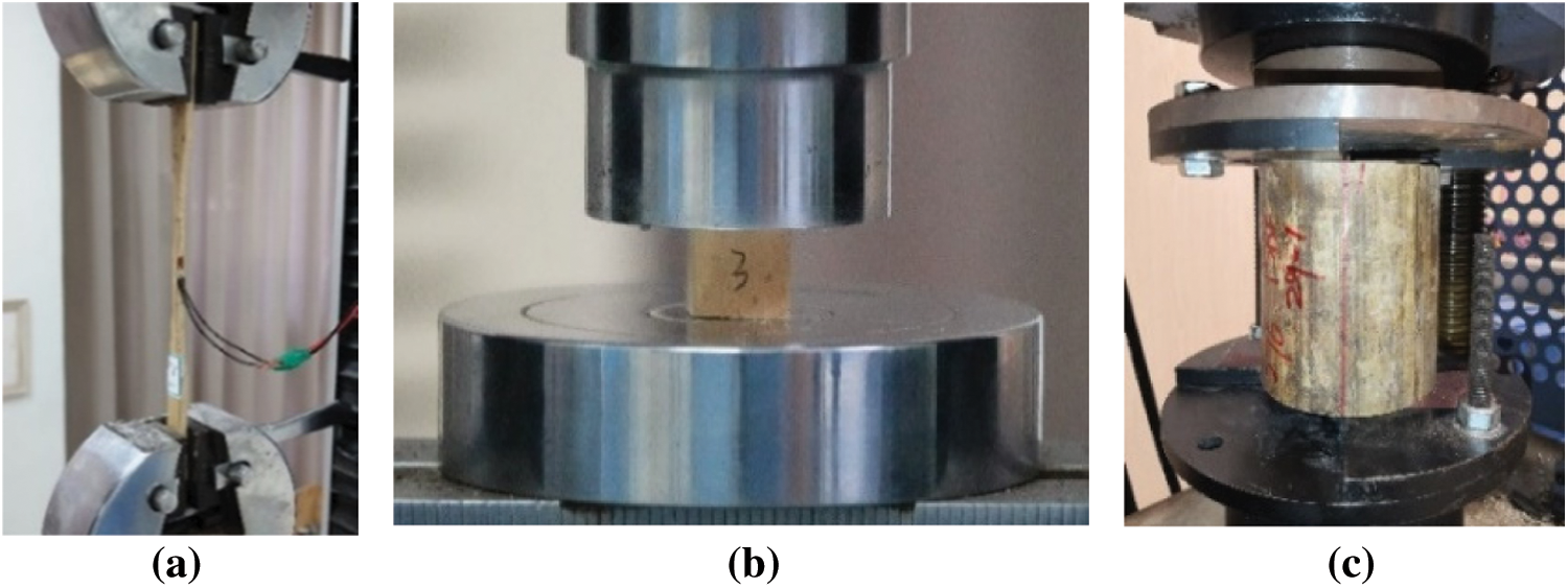
Figure 2: Tests of mechanical properties of Moso bamboo (a) Tests of tensile strength, (b) Tests of compressive strength, (c) Tests of shear strength. Adapted with permission form reference [25], Copyright © 2022, Tech Science Press
The average outer diameters of the Moso bamboos used for the tested specimens are about 100 mm, and the average diameter-to-thickness ratio D/t (the ratio of the outer diameter D of to the wall thickness t) was controlled within about 10. The twenty connection specimens were designed by controlling the end distances of bolt holes and the bolt diameters. Four kinds of end distances were designed, which were 50, 80, 110 and 140 mm, respectively. Accurately locating of bolt hole position was decided by using a certain length of wood rod drawing point before drilling. In order to install bolts more conveniently, the diameters of the bolt holes in the Moso bamboo are 2 mm larger than those of the bolts. The ordinary galvanized bolts of Grade 4.8 were used in the test, and the bolt is a full thread screw to ensure that the bamboo wall acts on the threaded area. The bolts used for these connections were M8, M10, M12, M14, M16. The geometrical dimensions of the embedded steel plates are shown in Fig. 3 High-strength non-contraction materials produced by New Manchester United Company were selected as the grouting material CGM-340. Technical specifications of the grouting materials provided by manufacturers. The compressive strength of the grouting material used in this experiment was 40 MPa, which meets the specification GB/T 50448–2015 [26]. The vertical expansion rate is greater than 0.02%. After 30 min, the fluidity of the grouting material exceeds 310 mm, which has good fluidity. Meanwhile, the grouting material has no corrosive effect on the reinforcement.
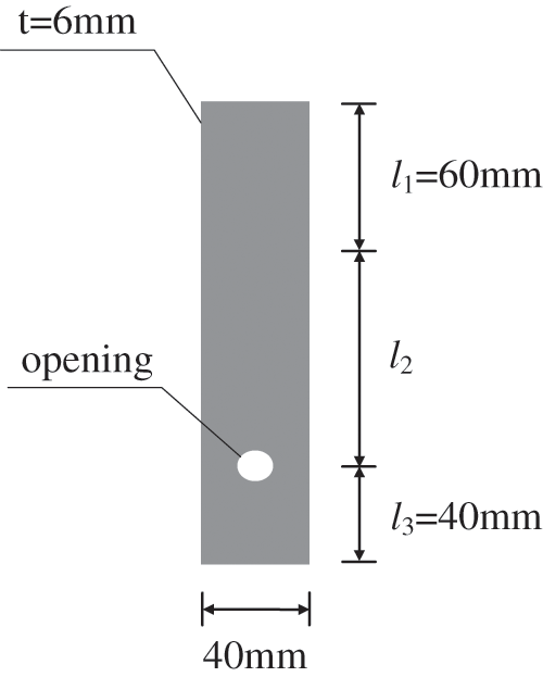
Figure 3: Embedded steel plates
As a biological material, the wall thicknesses of Moso bamboo are of slight differences. Therefore, the average value tm of t1, t2, t3 and t4 was taken as the standard wall thickness, as shown in Fig. 4. The geometrical parameters of each connection specimen are shown in Table 2. The test specimen “GS-16-140” was taken as an example to explain the naming rule: “GS” represents the name of the test specimen, “16” refers to the bolt type M16, and “140” means the bolt end distance of 140 mm.
Figure 4: Measurement method for wall thicknesses of Moso bamboos. Adapted with permission form reference [25], Copyright © 2022, Tech Science Press
The bamboo connection tests were conducted by a universal testing machine with the maximum load of 100 kN as shown in Fig. 5. The displacement-controlled loading rate was 2 mm/min from the onset of loading to the failure of connection, and the axial static loading method was used to acquire the force-displacement curves of each connection. The tensile test was stopped when the specimen was damaged. The clamping ends of the steel plate were clamped by the chuck of the testing machine, and the steel plates and the Moso bamboo were connected by bolts to transmit force.
Figure 5: Test setup of Moso bamboo connections (a) Schematic diagram of test device, (b) Loading Protocol
3 Test Results and Discussions
3.1 Bearing Capacities and Failure Modes of Connections
Typical load-displacement curves obtained from the tensile tests are shown in Fig. 6. These curves can be divided into four typical stages according to the deformation characteristics of specimens.
Figure 6: Typical load-displacement curves [26]
1) Stage ①: Initial slip stage (OA section): while the increase in the displacement of the connection at the beginning of loading was larger and the increase in load was small, the load-displacement curve appeared in the concave downward trends. The reason is that the clamping ends of the testing machine slipped at the beginning of loading, which resulted in producing the initial displacement of the connection. The grouting materials made the connection between the various components dense after the initial slipping.
2) Stage ②: Elastic deformation stage (AB section): When the connection displacement continued to increase and the initial slipping stage ended, the connections began to move into the elastic deformation stage, thus the load-displacement curve became linear, namely the bearing capacity and deformation linearly increased. Then the load-displacement curve reached the first extreme point (point B in Fig. 6). The bearing capacity of point B on the ordinates is referred to as F1 in Table 3.
3) Stage ③: Cracking stage (BC section) or plastic yielding stage (BF section): After the elastic stress stage, the load-displacement curve dropped sharply section (i.e., BC section) if the grouting material was cracked or the bamboo was crushed. If the grouting material did not crack and the bamboo did not split, and the bolt hole yielded under pressure, the connection went into the plastic yield stage, following that the load-displacement curve appeared as a BF section.
4) Stage ④: Bending stage of the bolt shank (CDE section): After the grouting material was cracked, it stopped working. The steel plate transmitted the tensile force to the bolts through the bolt holes. The bolts were subjected to bending deformation by the concentrated force in the middle of the bolt shank, and then the bolt entered the plastic stage. The load-displacement curve reappeared in the ascending trend, and specimens finally failed after the bearing capacity reached the second extreme point (point D in Fig. 6). The ordinate of point D is recorded as F2 in Table 3, and the abscissa as y1.
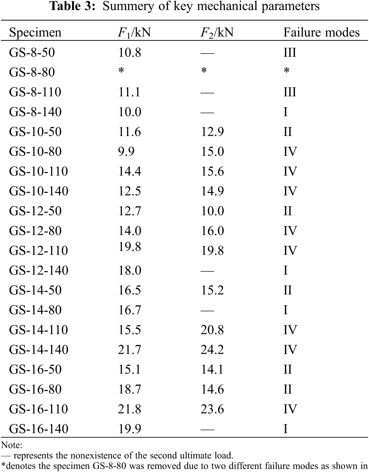
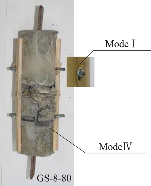
Figure 7: Different failure modes at both ends of GS-8-80
For failure modes in all the connection tests, four typical failure modes can be recognized, as shown in Fig. 8. These failure modes were controlled by the bolt diameters and the end distances of bolt holes. The failure processes of these failure modes were separately analyzed. The classifications for the different failure modes of the different connection specimens can be seen in Table 3.

Figure 8: Four typical failure modes of connection specimens (a) Mode I, (b) Mode II, (c) Mode III, (d) Mode IV
1) Failure mode I (Fig. 8a): When the inner wall of the bamboo was relatively smooth, the friction between the grouting materials and the inner wall was quickly overcome in the initial slipping stage of the connection. The embedded steel plates and the bolt shanks were tightly wrapped by the grouting materials to form a rigid body, and the grouting materials did not produce cracks when the whole displacement occurred. Then the bolt hole area of the Moso bamboo was squeezed by the bolts. Then the bolts slipped causing the bolt hole to yield failure, and the bolt hole wall was flat, thus the bolts were slightly bent under shear conditions. There was no sudden drop and no second extreme points in the load-displacement curves.
2) Failure mode II (Fig. 8b): When the end distance of bolt hole was small, the shear capacity of bamboo was less than the bearing capacity of the bolt holes, and the bamboo was prone to splitting failure, while the bolt hole walls were rough, and the fiber bundle distributions were disordered. Meanwhile, when the diameter is large, the bamboo occurs punching shear failure. In the load-displacement curve, there was no second extreme point after the sudden drop, or the second extreme point was smaller than the first extreme point.
3) Failure mode III (Fig. 8c): When the friction force on the inner wall of the bamboo was sufficient, the grouting materials were first cracked under the tensile force, and then the steel plates transmitted the tensile force to the bolts through the bolt holes. The grouting materials filled the thread gap as shown in Fig. 9, which increased the stiffness of the bolts and resisted bending deformation. Due to the small diameter of the bolt, the bolts were sheared to fracture eventually. Additionally, the bolt fracture sound could be heard, and there were no cracks or yield slipping on the surface of the bamboos when the connection displacement was small. In the load-displacement curve, there was no second extreme point after the sudden drop.
4) Failure mode IV (Fig. 8d): When the friction force on the inner wall of the bamboo was sufficient, the grouting materials were first cracked, that is, the grouting material split from the section where the bolt was located in two parts, and then the steel plates transmitted the tensile force to the bolt through the bolt holes. Because the bolt has a large diameter and high shear strength, the bolts were bent and deformed under the tensile force of the steel plates. However, the bamboo walls and the nuts limited the bending deformation of the bolt shanks. When the bolt shanks were bent, the squeezing force was applied to both sides of the bamboo through the nuts, and finally the grouting materials at the bolt hole were cracked, as shown in Fig. 10. This is an ideal failure mode. In the load-displacement curves, the second extreme point appeared after the sudden drop, and the second extreme point was greater than the first extreme point.
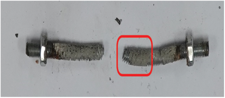
Figure 9: The bolt threads wrapped by grouting materials
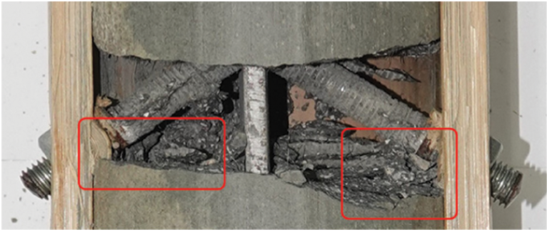
Figure 10: Grouting crushed at the bolt holes on both sides
3.2 The Effect of Bolt Diameters
3.2.1 The Effect of Bolt Diameters on Bearing Capacity in Failure Mode I
Failure mode I occurred in four of all specimens. The crushed area of bamboo walls in failure mode I is shown in the red area in Fig. 11. The factors influencing the bearing capacity of the connection are bolt diameter D and bamboo wall thickness tm. The load-displacement curves of the four specimens are shown in Fig. 12.
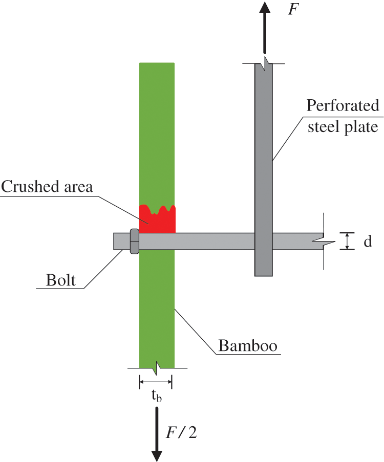
Figure 11: Damaged area of bamboo walls in failure mode I
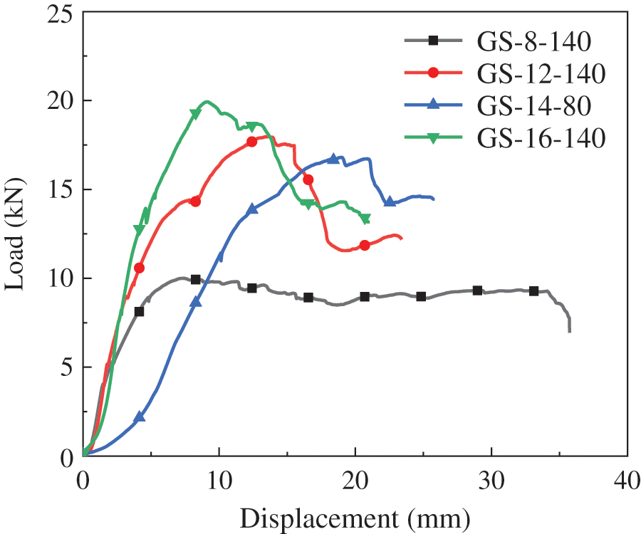
Figure 12: Load-displacement curves of connections classified by bolt diameters
According to F1,l in Eq. (1), to eliminate the influence of end distance of bolt holes, the influence of bolt diameters in failure mode I on connection failure load was compared in Fig. 13. According to F1,m in Eq. (2) to eliminate the influence of wall thickness on the bearing capacities of the connection as shown in Fig. 14.

Figure 13: The d-F1/l curves
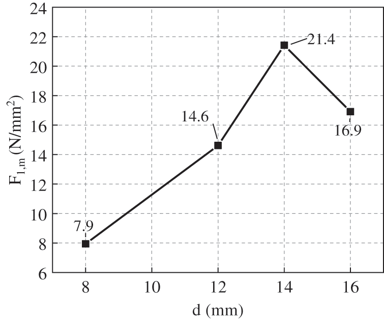
Figure 14: The d-F1, m/l curves
Figs. 13 and 14 show the variation trend of the bearing capacities of the connection is the same because the wall thickness of Moso bamboo in each specimen is similar, which has a negligible effect on the change trend of the bearing capacities of the connection when the wall thickness was eliminated. In the failure mode I, the bearing capacity increased with the increase of bolt diameter, but the bearing capacities decreased when the bolt diameter is too large for M16.
3.2.2 The Effect of Bolt Diameters on Bearing Capacity in Failure Mode II
For failure mode II, F1,l and F1,m are calculated according to Eqs. (1) and (2), respectively, as shown in Figs. 15 and 16 where the red dotted line indicates the specimen GS-16-50, and the black solid line indicates the specimen GS-16-80. The influencing trend of bolt diameters on the bearing capacities of each connection is the same as that in failure mode I, and the bearing capacity of the connection will decrease when the bolt diameter is too large.
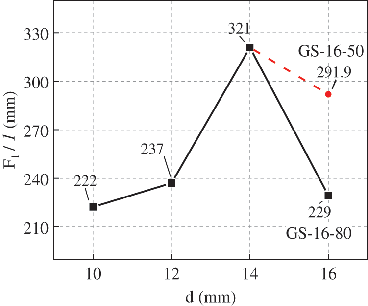
Figure 15: The d-F1/l curves
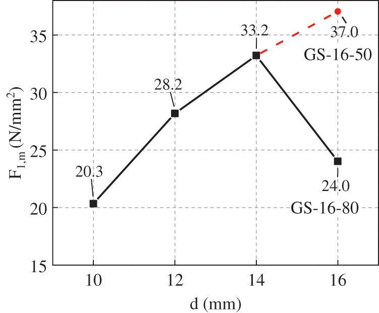
Figure 16: The d-F1, m/l curves
The failure modes of the connection are classified according to the bolt diameters, as shown in Fig. 17. It can be found that failure mode II occurred except for the connection of M8, and the distribution of failure mode II has no obvious relationship with bolt diameters.
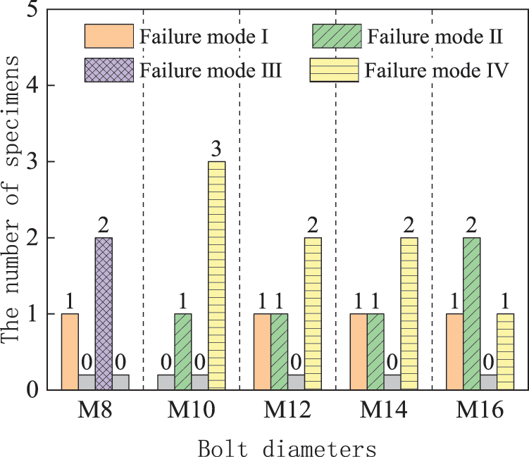
Figure 17: Distribution of specimen failure modes under different bolt diameters
3.2.3 The Effect of Bolt Diameters on Bearing Capacity in Failure Mode III
Only two specimens failed in mode III including GS-8-50 and GS-8-110. Their load-displacement curves are shown in Fig. 18 where their ultimate loads are similar and the bolt diameter is the same, although there is a huge difference between the end distances of bolt holes in the two specimens. The bolt is a weak part of each part of the specimen, so the bearing capacity of the specimen is controlled by the bolt.

Figure 18: Load-displacement curves
The failure modes are classified according to the ratios values d/D as shown in Fig. 19 where d is the bolt diameter and D is the outer diameter of the bamboo. For the failure mode III, the ratio values d/D are 0.0758 and 0.0819 for GS-8-50 and GS-8-110, which are similar and distributed on the left side of the abscissa. It can be seen that the failure mode III is related to the relative dimensions of bolt diameters. When the bolt diameter is small relative to the outer diameter of Moso bamboo, the connection is prone to bolt shear failure.

Figure 19: The d/D interval distributions under various failure modes
3.2.4 The Effect of Bolt Diameters on Bearing Capacity in Failure Mode IV
The load-displacement curves of all joints in failure mode IV were analyzed according to the distance of the bolt hole end. Under the same end distance of bolt hole, the changing trend of ultimate bearing capacity F2 is shown in Fig. 20 in which the ultimate bearing capacities of the connection increase with the increase of bolt diameters in the failure mode IV. This is because the stiffness of the bolt increases with the increase of bolt diameter, and the bending strength of the bolt also increases, hence it is not easy to bend. The variation curves of ultimate bearing capacities of connections under unit wall thickness are shown in Fig. 21. The ultimate bearing capacity of the connection under unit wall thickness fluctuates with the increase of bolt diameter, and there is no obvious variation trend.
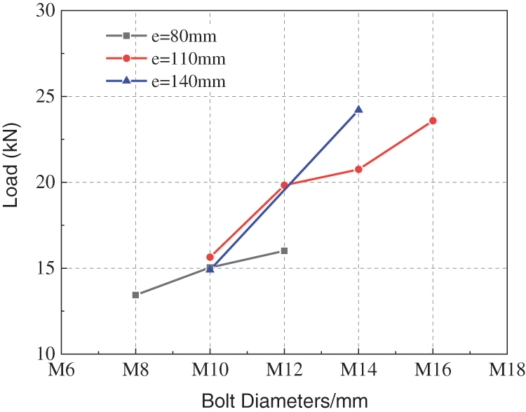
Figure 20: Influence of bolt diameters on ultimate bearing capacities

Figure 21: Ultimate bearing capacity of unit wall thickness
3.3 The Effect of End Distances of Bolt Holes
The connection load-displacement curves are classified according to the bolt diameters, as shown in Fig. 22. The variation trend of the ultimate bearing capacity of the connection with the bolt hole end distance is shown in Fig. 23. It can be seen from Figs. 22 and 23 that the larger end distances of bolt holes cannot improve the ultimate bearing capacities of the connections when the bolt diameters varied from M8 to M10, even the bearing capacities are reduced. For example, the ultimate bearing capacity of the connection specimen GS-8-110 or GS-8-140 is less than that of specimen GS-8-80. When the bolt diameters increase to M12~M16, the ultimate bearing capacities of the connection increase with the increase of end distances of the bolt holes.
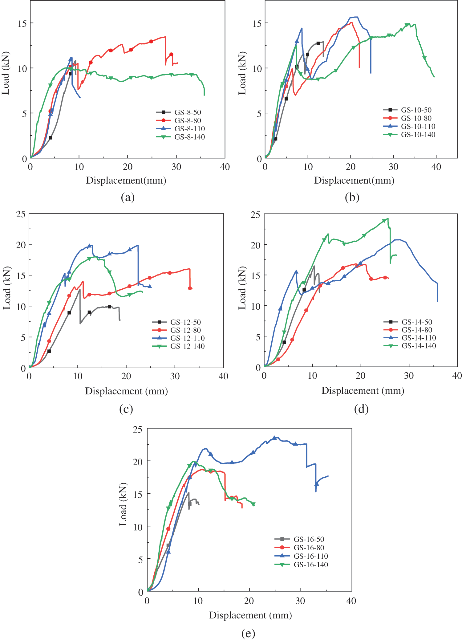
Figure 22: Load-displacement curves classified by bolt diameters (a) M8, (b) M10, (c) M12, (d) M14, (e) M16

Figure 23: The influence of the end distances
The failure modes of each connection are classified according to different end distances as shown in Fig. 24. Failure mode I occurs when the end distances of bolt holes are 80 and 140 mm. According to the previous analysis, the main influencing factor of failure mode I is the friction between grouting materials and the inner wall of Moso bamboo.

Figure 24: Distribution of specimen failure modes
The failure mode II only occurs when the end distance is 50 mm because the shear capacity of Moso bamboo is insufficient, resulting from the too small end distance of the bolt hole, which is easy to result in the splitting failure, and this phenomenon should be avoided by limiting the end distance of the bolt hole. All failure modes are classified according to the ratio value l/d, as shown in Fig. 25. The l/d values of failure mode II are concentrated in the range of 3.23~5.20, based on which the failure mode II is related to the relative dimensions of bolt diameters, thus this mode occurred when the bolt diameter is small relative to the outer diameter of Moso bamboo. It should be avoided by limiting the diameter of the bolt by construction measures, namely l/d ≥ 8.

Figure 25: The l/d interval distributions under different failure modes
According to the previous analysis, the small bolt diameters led to failure mode III, namely the bolt shear fracture. It is suggested that the bolt type should be designed to meet d/D ≥ 0.09.
The failure mode IV is more evenly distributed in the end distances of bolt holes except 50 mm, and the end distance of bolt holes is not a controlling factor.
3.4 The Bearing Capacity Comparison with Other Connection Modes
Compared with the external clamp steel plate connection without filling grouting material [25], the bearing capacity of the connection with embedded steel plate and grouting material is improved. The average ultimate bearing capacity of the external clamp steel plate connection is 13 kN, while that of the embedded steel plate and grouting connection is 18.75 kN, which is 44.2% higher than that of the external steel plate connection. From the aspect of ultimate bearing capacity under unit wall thickness, eliminating the influence factors of different bamboo wall thickness in each connection, the ultimate bearing capacity of embedded steel plate grouting connection under unit wall thickness reaches 2.31 kN/mm, which is 69.9% higher than that of external clamp steel plate connection.
According to the comparative analysis based on the load-carrying capacities and failure modes of the implemented bamboo connection tests, the analytical model of bolted bamboo connection with embedded steel plates and grouting materials is simplified. Based on the Johansen theory associated with four basic assumptions as follows, the theoretical bearing capacity of the connections was predicted, which can provide a reference for the design of connection bearing capacity.
The basic assumptions are:
(1) Ignore the tangential friction between the bolt and the bolt hole of the bamboo;
(2) The bolt holes on both sides of the bamboo walls are aligned and their load-carrying behavior is evenly distributed;
(3) The wall thickness of the bamboo is uniform, and there are no large differences in the wall thickness of the bolt holes on both sides;
(4) After the grouting materials cracks, it immediately exits from work and no longer receives force.
When the failure mode I of the connectors occurs, the grouting material does not crack. The grouting material encapsulates the screw and the embedded steel plate into a whole. The round bamboo at the screw hole bears the compressive stress given by the screw, leading to the yielding of the bamboo wall near the bolt hole. Hence the bolt is taken as the separating body for force analysis as shown in Fig. 26 to obtain the mechanical equilibrium formula as given in Eq. (3).

Figure 26: Failure mode I
where
F is the design value of the bearing capacity of the connection, kN;
fem is the compression strength of Moso bamboo, which can be obtained according to material property test, N/mm2;
d is the bolt diameter, mm;
tb is the wall thickness of Moso bamboo, mm;
The tested value of the bearing capacities of the connections with failure mode I are compared with the calculated value as given in Eq. (3) in Table 4. The proposed calculation formula is close to the test value, and their ratio range is 0.96~1.36 between test and calculated results, and the average ratio of the test-to-calculated value is 1.15, which indicates that the proposed calculation formula can better predict the failure load of the connection. Thus the formula can be used in the design of the connection, and the actual stress of the connection is close to Fig. 26.
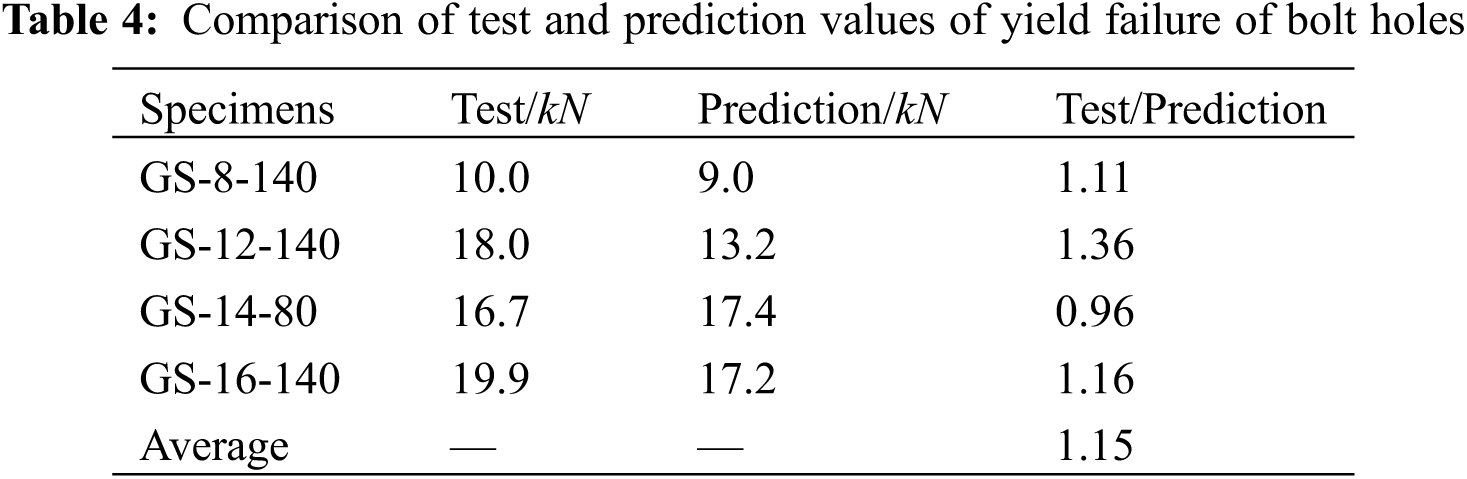
However, the failure mode I is not an ideal failure mode. Compared with grouting materials and bolts, the strength and deformation capacities of Moso bamboo are smaller, so moso bamboo becomes the main undertaker of failure mode I. In the practical design and application, the roughness of the inner wall of Moso bamboo should be increased to improve the friction between Moso bamboo and grouting materials. The three materials coordinate to avoid the occurrence of the failure mode I.
Failure mode IV is a relatively ideal failure mode. Each component of the connection is involved in the stress of the connection. Firstly, the grouting material bears tensile force and cracks occur at the bolt, because the existence of the bolt makes the cross section minimum. When the grouting material cracks, the upper part of the screw grouting material exits work. Subsequently, the bolt bears the concentrated force transmitted by the steel plate in the middle of the span, and the bending deformation occurs, and the node deformation increases. When the bolt is bent, both sides of the nut and the bamboo wall limit the bolt bending. While the grouting material increases the deformation of the connector and delays the damage of the connector, the grouting material within the nut bears the pressure transmitted by the nut and improves the bearing capacity of the joint.
According to the failure characteristics of failure mode IV, the simplified model of connection is shown in Fig. 29. The corresponding formula is expressed by Eq. (4).
where
Fc indicates the compressive bearing capacity of grouting materials at bolt holes on both sides, kN;
fc means the compressive strength of grouting material after 3 days based on GB/T 50448-2015 [26],
fc = 40 MPa;
Am denotes the effective bearing area of grouting material, mm2, as represented by Eq. (5).
where
S is the opposite width determined according to GB/T 6170-2015 [27] (see Table 5), mm;
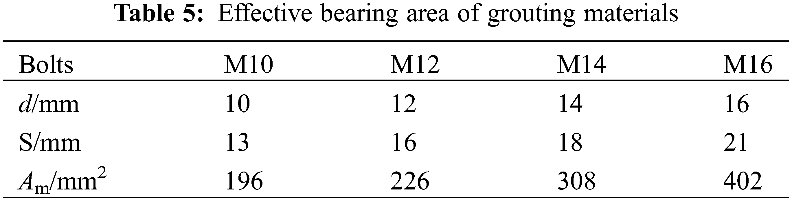
d is the bolt diameter, mm.
The coefficient of 0.6 is the reduction factor of nuts. The nuts on both sides limit the bending deformation of the bolts after being pulled by the steel plates, and the radial stiffness of round bamboo is small, the limiting ability of nut deformation is limited, thus the nut rotates. However, after the grouting material cracking, the grouting material in the upper part of the screw exits from work, and only part of the grouting material in the lower part of the screw is subject to nut extrusion. The thick red line in Fig. 28 is the contact surface between the nut and the outer surface of the bamboo. The bearing area of the grouting materials is simplified as the area of the half ring shown in the red area in Fig. 27. Meanwhile, considering the uneven compression, the main area is concentrated on the edge of the nuts. Therefore, the reduction factor of the ring area is 0.6.
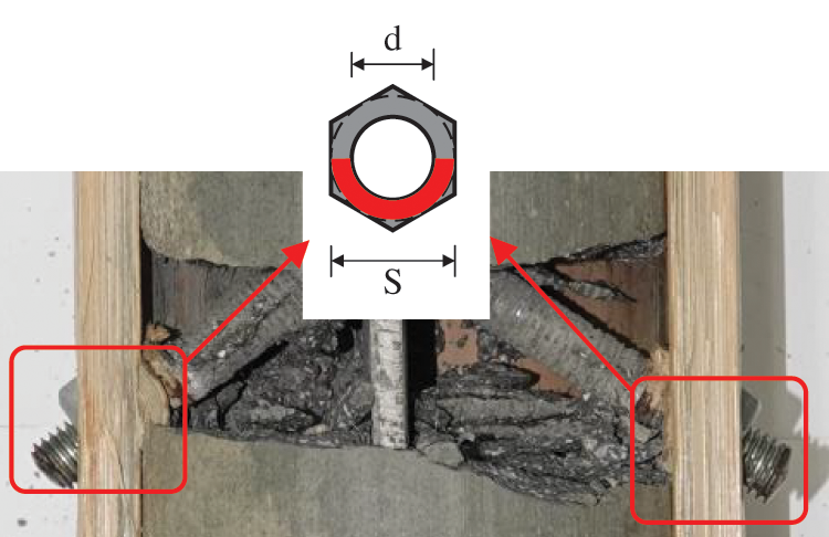
Figure 27: Effective bearing area of grouting materials

Figure 28: Contact surface of bolt and bamboo outer wall

Figure 29: Failure mode IV
According to Fig. 29, the mechanical equilibrium conditions based on Johansen’s plastic yield theory [28] is established to solve the theoretical bearing capacity of the connection, as represented by Eq. (6).
where
F is the maximum bearing capacity of the connection, kN;
fem is the compressive strength value of Moso bamboo according to the material property test, MPa;
tb is the wall thickness of Moso bamboo in the specimens, mm;
a or b is the length of the extrusion area in the wall thickness of Moso bamboo, mm;
Mu is the plastic bending moment value of the bolt, N·mm;
d is the bolt diameter, mm;
D is the outer diameter of Moso bamboo, mm;
Fc is the compressive bearing capacity of grouting materials at the bolt holes on both sides, kN;
y2 is the limit displacement of the connection, mm;
According to the Eq. (6), it can be concluded that:
From the recommendations of NDS-2005 [29], considering the complete development of the bolt plasticity, the plastic bending moment of bolt as follows:
where
fub is the tensile strength of Grade 4.8 galvanized bolt bolts used in this test, fbu = 400 MPa [30];
kw is the plastic development coefficient of bolt, kw = 1.7.
Combining Eq. (7) with Eq. (8), according to the root-finding formula and neglecting the negative solution, Eq. (9) was obtained:
where the ultimate displacement of the connection, y2. Since y2 cannot be determined at the initial stage of design, the calculation formula of ultimate bearing capacity was reduced to a certain extent. Therefore, the design formula proposed in this paper is modified to Eq. (10) on the basis of Eq. (9).
The calculation value F, design value F’ and test value F2 of bearing capacity of each connection with failure mode IV are compared and analyzed as shown in Table 6. The calculated value F is close to the test value F2, and their F/F2 range is 0.71~1.28 with an average value of 0.96, indicating that the bearing capacity calculation formula can better predict the connection failure load, which is close to the actual test value.
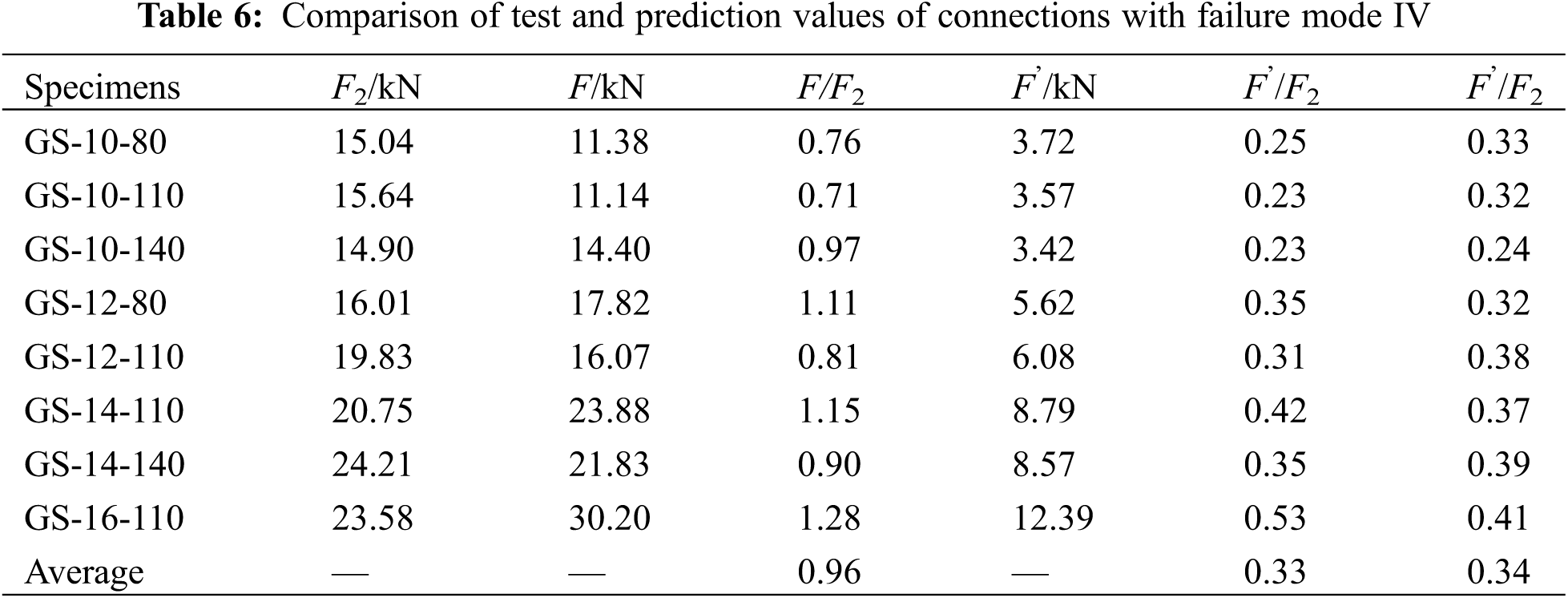
The design value F’ is relatively conservative, and the ratio range of F’/F2 is 0.23~0.53 with an average of 0.33, indicating that there is a certain degree of safety according to the F’ bearing capacity during the design. The average value of F’/F2 is 0.34, which indicates that the design value is about 1/3 of the calculated value, which is equivalent to three times of the calculated value.
Based on the static tension tests of bolted Moso bamboo connections with embedded steel plates and grouting materials, their load-bearing capabilities and failure modes were discussed under different connection configurations. The analytical formulas for failure modes I and IV were derived according to mechanical equilibrium, while structural measures are recommended for other failure modes. This study can reveal the following conclusions:
(1)For Moso bamboo connections with embedded steel plates and grouting materials, the deformation and failure processes can be mainly characterized by four stages: initial sliding stage, elastic deformation stage, grouting material cracking stage and bolt bending stage.
(2)The bearing capacity of the connections increases with the increase of the bolt diameter, but the effect is not obvious when the bolt diameter is too large. Meanwhile, there is no obvious linear relationship between the bolt end distance and the bearing capacity of the connections.
(3)There are four failure modes in this experiment. Failure mode I and failure mode IV are ductile failures, and failure mode IV is a relatively ideal failure mode. The failure mode I can be avoided to increase the roughness of the inner wall of Moso bamboo and the friction between the grouting material and the inner wall of Moso bamboo. The calculated value of the failure mode IV is close to the experimental value. The average value of F/F2 is 0.96. Failure mode II and failure mode III are brittle failures, which should be avoided as far as possible. The failure mode II can be prevented by limiting the end distance of the bolt hole such as l/d ≥ 8, while the failure mode III is controlled according to the limit bolt diameter such as d/D ≥ 0.09.
(4)Filling the joints with grouting material can slow down the yield of bolts and improve the bearing capacity of joints.
(5)In this paper, all specimens are only one. Due to the large variability of bamboo, it is necessary to further carry out relevant experiments to verify the design suggestions proposed in this paper, so as to ensure the design safety and provide a basis for establishing a complete system of theory and calculation method.
Funding Statement: The authors would like to appreciate the support from 111 Project (Grant No. B18062), the Graduate Research and Innovation Foundation of Chongqing in China (Grant No. CYS20026) and the National Key Research and Development Program of China (Grant No. 2017YFC0703504).
Conflicts of Interest: The authors declare that they have no known competing financial interests or personal relationships that could have appeared to influence the work reported in the current study.
References
1. Zhang, L. F., Liu, W. Q., Wang, L., Ling, Z. B. (2019). Mechanical behavoir and damage monitoring of pultruded wood-cored GFRP sandwich componennts. Composite Structures, 215(6), 502–520. DOI 10.1016/j.compstruct.2019.02.084. [Google Scholar] [CrossRef]
2. Wang, Z., Wang, Y. L., Cao, Y., Gao, Z. Z. (2018). Measurements of the shear modulus of materials by the free-plate toriaonal mode shape method. Journal of Testing and Evaluation, 47(2), 1163–1181. [Google Scholar]
3. Archila-santos, H. F., Ansell, M. P., Walker, P. (2012). Low carbon construction using Guadua bamboo in colombia. Key Engineering Materials, 517, 127–134. DOI 10.4028/www.scientific.net/KEM.517.127. [Google Scholar] [CrossRef]
4. Cao, L., Coops, N. C., Sun, Y., Ruan, H. H., Wang, G. B. et al. (2019). Estimating canopy structure and biomass in bamboo forests using airborne LiDAR data. ISPRS Journal of Photogrammetry and Remote Sensing, 148, 114–129. DOI 10.1016/j.isprsjprs.2018.12.006. [Google Scholar] [CrossRef]
5. Chung, K. F., Yu, W. K. (2002). Mechanical properties of structural bamboo for bamboo scaffoldings. Engineering Structures, 24(4), 429–442. DOI 10.1016/S0141-0296(01)00110-9. [Google Scholar] [CrossRef]
6. Zhou, F. C. (1981). Study on physical and mechanical properties of bamboo. Journal of Nanjing Forestry University (Natural Science Edition), 2, 1–32 (in Chinese). [Google Scholar]
7. Xiao, Y., Li, J. (2015). The state of the art of modern bamboo structures. Industrial Construction, 45(4), 1–6. [Google Scholar]
8. Xie, J. L., Qi, J. Q., Hu, T. X., de Hoop, C. F., Hse, C. Y. et al. (2016). Effect of fabricated density and bamboo species on physical-mechanical properties of bamboo fiber bundle reinforced composites. Journal of Materials Science, 51(16), 7480–7490. DOI 10.1007/s10853-016-0024-3. [Google Scholar] [CrossRef]
9. Zhang, X. C., Zhou, Z. Z., Zhu, Y. D., Dai, J. F., Yu, Y. M. et al. (2019). High-pressure steam: A facile strategy for the scalable fabrication of flattened bamboo biomass. Industrial Crops & Products, 129, 97–104. DOI 10.1016/j.indcrop.2018.11.061. [Google Scholar] [CrossRef]
10. Hong, C. K., Li, H. T., Lorenzo, R., Wu, G., Corbi, I. et al. (2019). Review on connections for original bamboo structures. Journal of Renewable Materials, 7(8), 713–730. DOI 10.32604/jrm.2019.07647. [Google Scholar] [CrossRef]
11. Cui, J. H., Qin, Z., Masic, A., Buehler, M. J. (2020). Multiscale structural insights of load bearing bamboo: A computational modeling approach. Journal of the Mechanical Behavior of Biomedical Materials, 107, 103743. DOI 10.1016/j.jmbbm.2020.103743. [Google Scholar] [CrossRef]
12. Tang, G., Yin, L. F., Li, Z. J., Li, Y., You, L. G. (2019). Structural behaviors of bolted connections using laminated bamboo and steel plates. Structues, 20, 324–339. DOI 10.1016/j.istruc.2019.04.001. [Google Scholar] [CrossRef]
13. Carrasco, E. M., Smits, M. C., Alves, R. C., Pizzol, V. D., Oliveira, A. C. et al. (2021). Mantilla GluBam beams: Influence of the roughness of the bamboo laminas on the shear stress and the sliding modulus of bonded joint. Biosystems Engineering, 203(3), 98–108. DOI 10.1016/j.biosystemseng.2020.12.016. [Google Scholar] [CrossRef]
14. Zhang, H., Li, H. T., Li, Y. J., Xiong, Z. H., Zhang, N. N. et al. (2021). Effext of nods on mechanical properties and microstructure of laminated bamboo lumber units. Construction and Building Materials, 304(6), 124427. DOI 10.1016/j.conbuildmat.2021.124427. [Google Scholar] [CrossRef]
15. Villegas, L., Morán, R., García, J. J. (2019). Combined culm-slat Guadua bamboo trusses. Engineering Structures, 184(1), 495–504. DOI 10.1016/j.engstruct.2019.01.114. [Google Scholar] [CrossRef]
16. Huang, T., Zhuo, X. (2022). Experimental study on the bending properties of grouting butt joints reinforced by steel plate embedded in bamboo tube. Journal of Renewable Materials, 10(4), 993–1005. DOI 10.32604/jrm.2022.017373. [Google Scholar] [CrossRef]
17. Wang, F. L., Yang, J. (2020). Experimental and numerical investigations on load-carrying capacity of dowel-type bolted bamboo joints. Engineering Structures, 209(15), 109952. DOI 10.1016/j.engstruct.2019.109952. [Google Scholar] [CrossRef]
18. Sonar, I. P., Siddhaye, V. R. (2009). Theoretical and experimental investigation on single and double bolted bamboo joint under axial tension. Journal of Structural Engineering, 36(3), 164–171. [Google Scholar]
19. Fu, Y. G., Wang, M. Y., Ge, H. B., Li, L. (2012). Experimental study of mechanical properties of bamboo’s joints under tension and compression load. Advanced Materials Research, 450, 749–755. [Google Scholar]
20. Moran, R., García, J. J. (2019). Bamboo joints with steel clamps capable of transmitting moment. Construction and Building Materials, 216(20), 249–260. DOI 10.1016/j.conbuildmat.2019.05.025. [Google Scholar] [CrossRef]
21. Moran, R., Muñoz, J., Silva, H. F., García, J. J. (2018). A bamboo beam-column connection capable to transmit moment. Materials Research Proceedings, 7, 35–44. DOI 10.21741/9781945291838. [Google Scholar] [CrossRef]
22. García, J. J., Benítez, C., Villegas, L., Moran, R. (2018). Thin steel rings as a feasible alternative to connect bamboo culms. Materials Research Proceedings, 7, 661–670. DOI 10.21741/9781945291838. [Google Scholar] [CrossRef]
23. Paraskeva, T., Pradhan, N. N., Stoura, C. D., Dimitrakopoulos, E. (2019). Monotonic loading testing and characterization of new multi-full-culm bamboo to steel connections. Construction and Building Materials, 201(20), 473–483. DOI 10.1016/j.conbuildmat.2018.12.198. [Google Scholar] [CrossRef]
24. JG/T 199-2007 (2007). Testing methods for physical and mechanical properties of bamboo used in building. Beijing, China: Architecture & Building Press. [Google Scholar]
25. Nie, S. D., Ran, S., Wu, D., Chen, J. Y., Wang, H. et al. (2022). Mechanical properties of moso bamboo connections with external clamp steel plates. Journal of Renewable Materials, 10(2), 487–510. DOI 10.32604/jrm.2022.017275. [Google Scholar] [CrossRef]
26. GB/T 50448-2015 (2015). Technical code for application of cementitious grout. Beijing, China: Architecture & Building Press. [Google Scholar]
27. Hexagon nuts, style 1 (2015). Beijing, China: Architecture & Building Press. [Google Scholar]
28. Johansen, K. W. (1949). Theory of timber connections. International Associantion Bridge and Structural Engineering, 9, 249–262. [Google Scholar]
29. ANSI (2005). National design specification for wood construction. Washington, DC: American Forest & Paper Association. [Google Scholar]
30. SAC (2010). Mechanical properties of fasteners Bolts, screws and studs GB/T 3098.1-2010. Beijing, China: Architecture & Building Press. [Google Scholar]
Cite This Article
 Copyright © 2023 The Author(s). Published by Tech Science Press.
This work is licensed under a Creative Commons Attribution 4.0 International License , which permits unrestricted use, distribution, and reproduction in any medium, provided the original work is properly cited.
 Downloads
 Citation Tools