 Open Access
ARTICLE
Study on Strength Reduction Law and Meso-Crack Evolution of Lower Layered Cemented Tailings Backfill
1
State Collaborative Innovation Center of Coal Work Safety and Clean-Efficiency Utilization, School of Civil Engineering, Henan
Polytechnic University, Jiaozuo, 454003, China
2
Provincial Key Laboratory of Underground Engineering and Disaster Prevention and Control, School of Civil Engineering, Henan
Polytechnic University, Jiaozuo, 454003, China
3
School of Civil Engineering, Henan Polytechnic University, Jiaozuo, 454003, China
* Corresponding Authors: Wenxiang Zhang. Email: ; Yunfei Wang. Email:
Journal of Renewable Materials 2023, 11(3), 1513-1529. https://doi.org/10.32604/jrm.2023.026008
Received 12 August 2022; Accepted 05 September 2022; Issue published 31 October 2022
Abstract
The green disposal of tailings solid waste is a problem to be solved in mine production. Cemented tailings filling stoping method can realize the dual goals of solid waste resource utilization and mined-out area reduction. However, the volume of the mined-out area of the open-pit method is larger than the filling capacity, resulting in the complex stratification of the underground backfill, and the strength of the backfill cannot meet the requirements. In this paper, according to the delamination situation, the specimens of horizontal and inclination angle layered cemented tailings backfill (LCTB) is made for a uniaxial compression test, and the failure process of delamination backfill is reduced by PFC. The results show that the corresponding reduction factor φ of horizontal LCTB is 0.560–0.932, and the corresponding φ value of inclination angle LCTB is 0.338–0.772. The failure mode of backfill in different layers is mainly manifested as a tensile failure. The PFC numerical simulation results are consistent with laboratory test results, which verifies the correctness of backfill failure. The research results provide a reliable theoretical basis for the strength design of backfill in goaf, which is of great significance for solid waste utilization and environmental protection.Keywords
Nomenclature
| | Uniaxial compressive strength reduction factor |
| | The compressive strength of layered backfill |
| | The compressive strength of complete backfill |
Mineral resources provide basic raw materials for social development, but a large number of tailings wastes are often generated due to technical problems in the process of resource development [1–4]. At present, tailings waste is mostly stored and processed in tailings ponds, occupying a large number of land resources and adversely affecting the ecological environment and social stability [5–7]. On September 08, 2008, the 980 adit tailing pond in the Xinta Mining Area of China had a particularly serious dam break accident, with a drainage capacity of 268,000 cubic meters and an area of 30.2 hectares of mud, resulting in 277 deaths, 4 missing and 33 injured. Under the new requirements of green, safe, and high-quality development, the green disposal of tailings solid waste resources is imminent. Tailings backfilling goaf is one of the effective ways to directly utilize tailings [8–10]. Tailings backfilling goaf reflects the green disposal of solid waste, which not only saves the construction cost of tailings reservoirs but also avoids environmental pollution, achieving both economic and environmental benefits [11–14].
As an important content in the application of extraction steam turbine with stowing, the study of the mechanical strength of backfill has always been attached importance to by scholars [15,16]. Tailings filling technology is cemented filling, namely tailings, gel materials, and water, according to the proportion mixed into slurry filling goaf. Mechanical properties of cemented tailings backfill are affected by water-cement ratio and slurry concentration [17,18]. Kesimal et al. [19] studied the influence of binder content on the short-term and long-term strength of cemented tailings backfill and showed that the short-term strength increased with the decrease in water-cement ratio, and its long-term strength showed a downward trend after reaching the peak value. Deng et al. [20] prepared a new type of cemented tailings backfill with waste rock, fly ash, limestone slag, and ordinary Portland cement, to study the influence of solid content on the mechanical properties of backfill. Wu et al. [21] studied the uniaxial compression and triaxial compression performance of cemented waste rock backfill under different cementing material dosages and concluded that the cementing material dosage had a positive linear relationship with the strength of cemented waste rock backfill. Wang et al. [22] discussed the mechanical properties of alkalized rice straw and tailings cemented tailings backfill (CTB) of different lengths and conducted uniaxial compressive strength and indirect tensile strength tests to improve the mechanical properties of backfill. The researchers carried out compressive and acoustic emission tests on layered filling bodies with different tailings cement-to-tailings (c/t) ratio, and obtained the relationship between compressive strength, elastic modulus and c/t ratio of layered filling bodies [23]. Cao et al. studied the mechanical properties of cemented tailings backfill under the influence of different structural factors, analyzed its influence law, and established a functional relationship [24]. Based on the damage theory and total differential rule, Fu et al. established the damage evolution model and strength criterion of layered cemented tailings backfill [25]. Other scholars have also done a lot of studies on the mechanical properties of backfill and achieved many results [26,27]. The structural strength design of cemented tailings backfill is of great significance to its engineering application in goaf.
Although many scholars have studied the influence of water-cement ratio, mass concentration and structural characteristics on the mechanical properties of backfill, the force of backfill under the influence of structural characteristics is more complex and the failure mode cannot be predicted. The rapid development of numerical simulation software solves the complicated mechanical model which cannot be realized by indoor mechanical experiments. PFC particle flow program is a kind of numerical software that can analyze and study macroscopic mechanical problems from a microscopic perspective. The research results are very close to the real situation [28], so it has been widely used. Yang et al. analyzed the interaction of parallel joints and their influence on the mechanical behavior of jointed rock mass through indoor mechanical experiments and PFC numerical simulation [29]. Huang et al. conducted mechanical experiments and PFC numerical simulation to conduct in-depth studies on strength instability behavior and crack evolution mechanism of rock specimens with three holes [30]. Bahaaddini et al. used PFC software to conduct a numerical simulation of uniaxial compression of rock mass with non-through joints and studied the influence of joint geometric parameters on its mechanical properties [31–33].
In this paper, the mechanical properties of the LCTB were explored through laboratory experiments, and the failure characteristics of the LCTB were analyzed with particle flow software. The cemented tailings backfill with the cement-tailings ratio of 1:4, filling interval time of 24 h, and concentrations of 65%, 70%, and 75% were designed and prepared. The number of horizontal layers of backfill is 1, 2, 3, and 4, respectively, and the inclination angle between layers is 15°, 30°, and 45°. According to the uniaxial compression experiment, the compressive strength variation and failure mechanism of the backfill were studied to explore the mechanical characteristics of the backfill. At the same time, the uniaxial compression process of the backfill was simulated based on the two-dimensional particle flow software (PFC2D) to analyze the internal crack evolution mechanism.
Aluminum tailings were used as the raw material in the experiment, as shown in Fig. 1a. 42.5R ordinary Portland cement was used as the cementing agent. Water for the experiment was taken from laboratory tap water. The backfill specimen mold adopts a high-transparent acrylic tube to facilitate observation and control of filling stratification and angle between layers. Its height is 100 mm and its inner diameter is 50 mm, as shown in Fig. 1b.

Figure 1: Experimental materials
2.2 Preparation of Cemented Tailings Backfill Specimen
The experiment is carried out from two angles: horizontally and angularly LCTB. The ratio of cement to tailings is set at 1:4, and the three concentrations were 65%, 70%, and 75%, respectively. The number of layers of the horizontal LCTB is successively set as one layer, two layers, three layers, and four layers, and the height of the filling slurry is successively 100, 50, 33.3, and 25 mm. Fig. 2 shows the sample preparation process of the cemented tailings backfill with different layer numbers. Through experiments on slurry flow angles of 65%–75% mass concentration, the measured angle varies from 13.7° to 46°, as shown in Fig. 3a. The inclination angles between layers were set as 15°, 30°, and 45° respectively. According to the samples of layered cemented fillings, the filling time interval of each layer is 24 h, and the compressive test is carried out after curing in the standard environment for 28 d. Fig. 3b shows the sample preparation process of cemented tailings backfill with different angles between backfill layers.

Figure 2: Preparation of horizontal LCTB
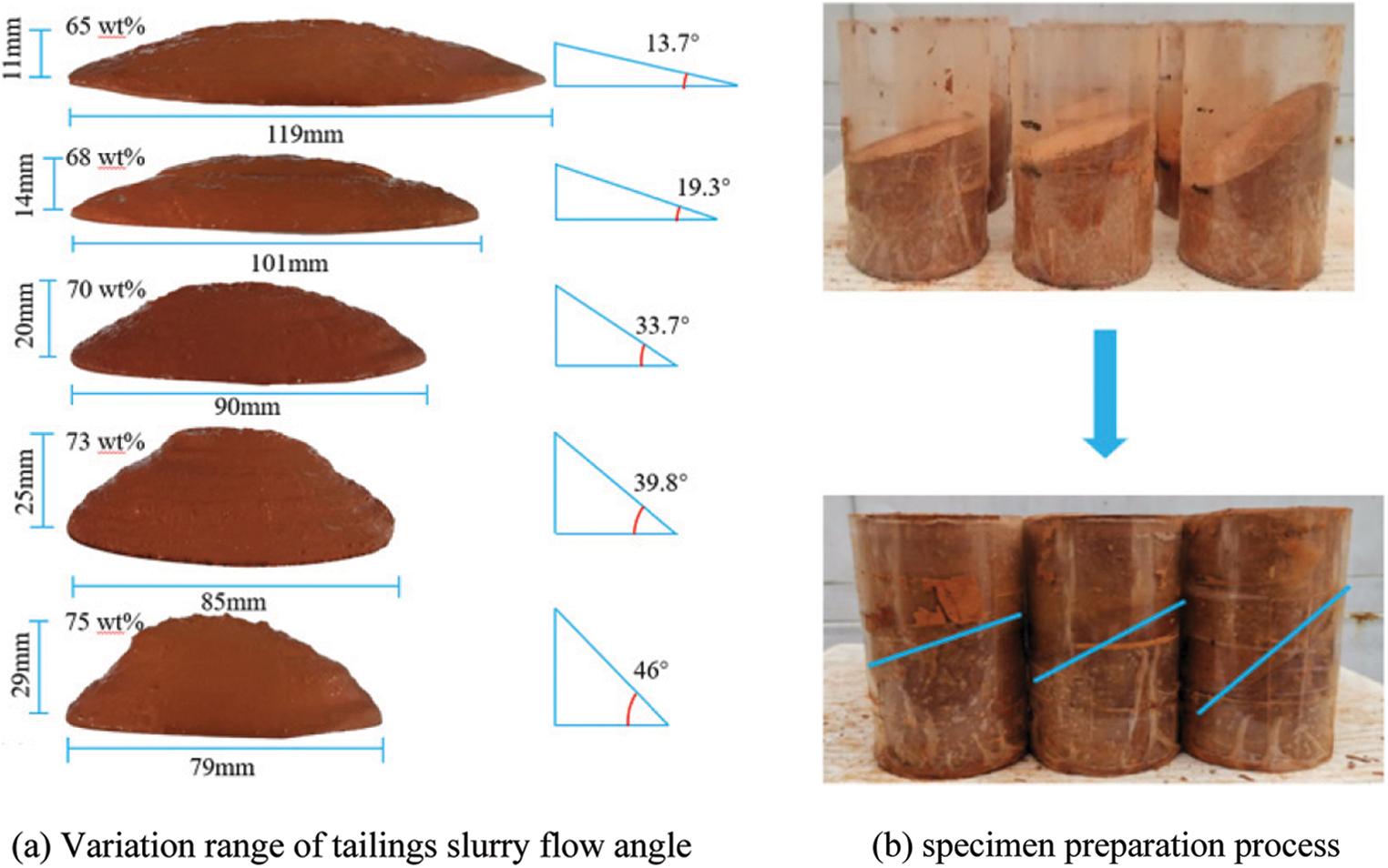
Figure 3: Specimen preparation of inclination angle LCTB
2.3 Uniaxial Compression Experiment
The uniaxial compression test is the most direct method to obtain mechanical parameters for backfill specimens. WDW-50 microcomputer-controlled electro-hydraulic servo press is used to carry out a uniaxial compression test on backfill specimens with different layer numbers and inclination angles, and the failure characteristics of samples are photographed and recorded, as shown in Fig. 4. In the uniaxial compression test, the maximum load of the loading control system was 50 kN, and the loading speed was kept unchanged at 0.5 mm/min. Three samples were tested in each group and the average strength was calculated.
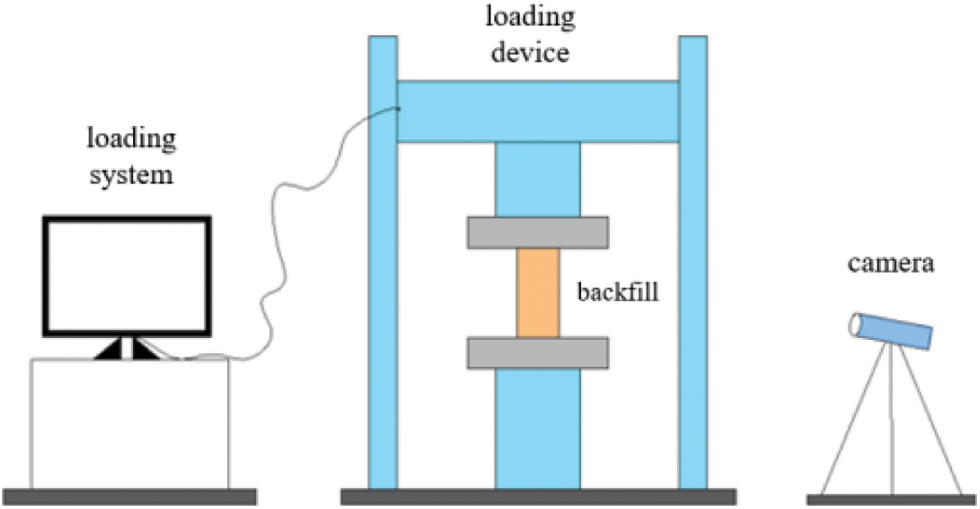
Figure 4: Uniaxial compression experiment and camera observation system
2.4 LCTB Discrete Element Simulation
To study the failure mode of LCTB from the microscopic point of view, the discrete element model of layered cemented filled body was established in the particle flow program PFC2D according to the results of uniaxial the compression test of filled body samples, and the uniaxial compression simulation test was carried out to analyze the fracture distribution characteristics at the microscopic point of view.
In PFC2D, force or bending moment is mainly transmitted between particles through bonding, and bonding models include the Linear Contact Bond Model, parallel Linear Parallel Bond Model, and Smooth-joint Contact Model. In the Linear Contact Bond Model, the particles have point contact, so the force-torque cannot be transmitted. When the normal or tangential force exceeds the corresponding bond strength, bond destruction occurs. The Linear Parallel Bond Model has a parallel bond bonding between the particles, which can transfer the force and torque between the particles. This model is closer to the real force situation of the filling sample than the contact bonding model. The Smooth-joint Contact Model is the polygonal particles instead of circular particles, which can transfer force and torque while inhibiting the rotation after particle bonding destruction, as shown in Fig. 5. To better reduce the stress state of the layered filling particles, a smooth joint model is used for the contact between different layers, and a parallel bonding model is used between the tailings particles.

Figure 5: Bonding model
3.1 Uniaxial Compressive Strength
In order to study the strength variation law of backfill under different stratification characteristics, the compressive tests of horizontally stratified backfill and angularly stratified backfill are carried out, and the results are shown in Table 1.

According to the analysis of Table 1, there is an obvious weakening effect of the LCTB. The uniaxial compressive strength of the horizontal LCTB decreases gradually with the increase of layer number. The compressive strength of the four layers backfill is the lowest with a minimum of 2.4 MPa, while the strength of the complete backfill is the highest with 5.05 Mpa. For the specimen with the same layer number, the uniaxial compressive strength increases gradually with the increase of filling mass concentration. However, the strength of the backfill with an inclination angle is far less than the overall strength of the horizontal LCTB. Therefore, the influence of angle factors on backfill strength is far greater than that of the number of slicing.
3.2 Strength Reduction Analysis of LCTB
According to the experimental results of uniaxial compressive strength (UCS), the strength of backfill decreases with the increase of layer number and inclination angle, and the layer number and inclination angle have an obvious weakening effect on the strength of backfill. Strength reduction calculation is performed for backfill with the different number of layers and different inclination angles, as shown in the equation.
where
The calculation results are shown in Table 2. Under the same solid mass concentration, the reduction coefficient φ decreases with the increase of stratification number and stratification angle. The corresponding value of φ for horizontal LCTB is between 0.560–0.932, and the corresponding value of φ for inclination angle LCTB is between 0.338–0.772. According to the analysis of reduction factor interval, the weakening effect of horizontal slant filling is lower than that of inclination angle LCTB, and the structural strength of horizontal LCTB is higher than that of inclination angle LCTB.

3.3 Influence Analysis of Layer Number and Inclination Angle Strength
Strength analysis of backfill for different LCTB. To analyze the quantitative relationship between the strength of the backfill and the layer number and inclination angle, the test results of four concentrations were fitted by linear, logarithmic, and polynomial methods, and the multiple correlation coefficient R2 of each fitting method was calculated.
The fitting results in Fig. 6 show that the polynomial fitting degree is the highest among the three fitting methods. R2 at 65%, 70% and 75% mass concentrations reached 99.38%, 98.84% and 97.2%, respectively. Therefore, the polynomial equation can better reflect the quantitative relationship between compressive strength and layer number. From Fig. 7, the R2 of exponential fitting was the highest, which was 99.49%, 98.52%, and 96.16%, respectively. Therefore, the exponential relationship can better reflect the quantitative relationship between compressive strength and interlayer angle.
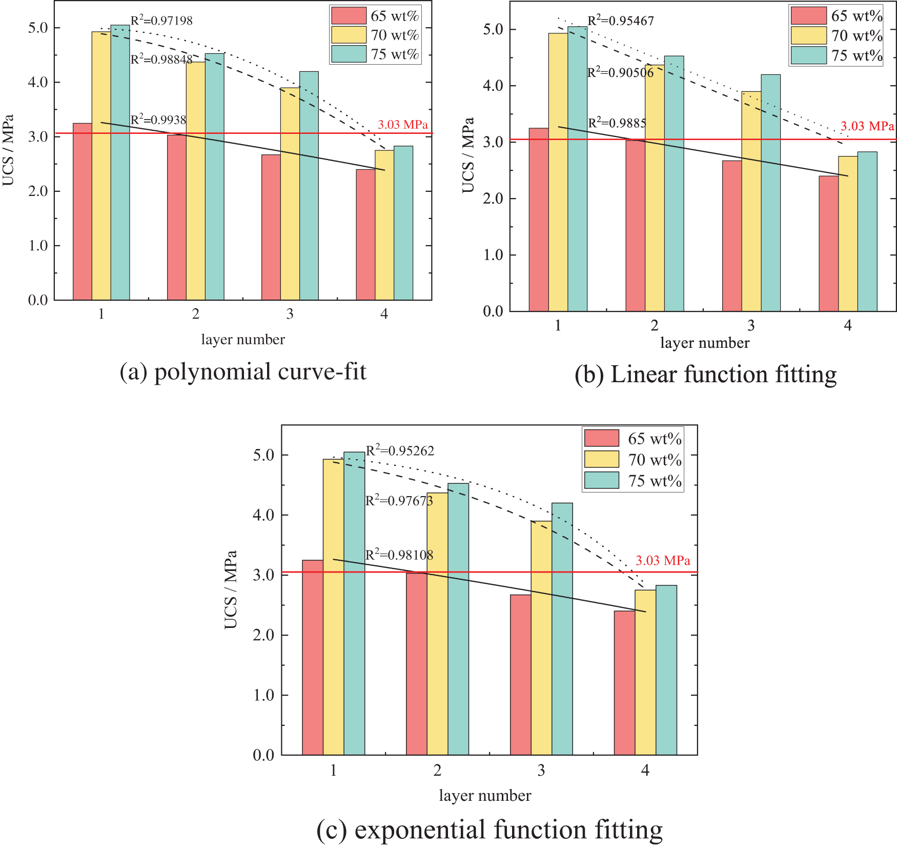
Figure 6: Fitting of uniaxial compressive strength and layer number of backfill
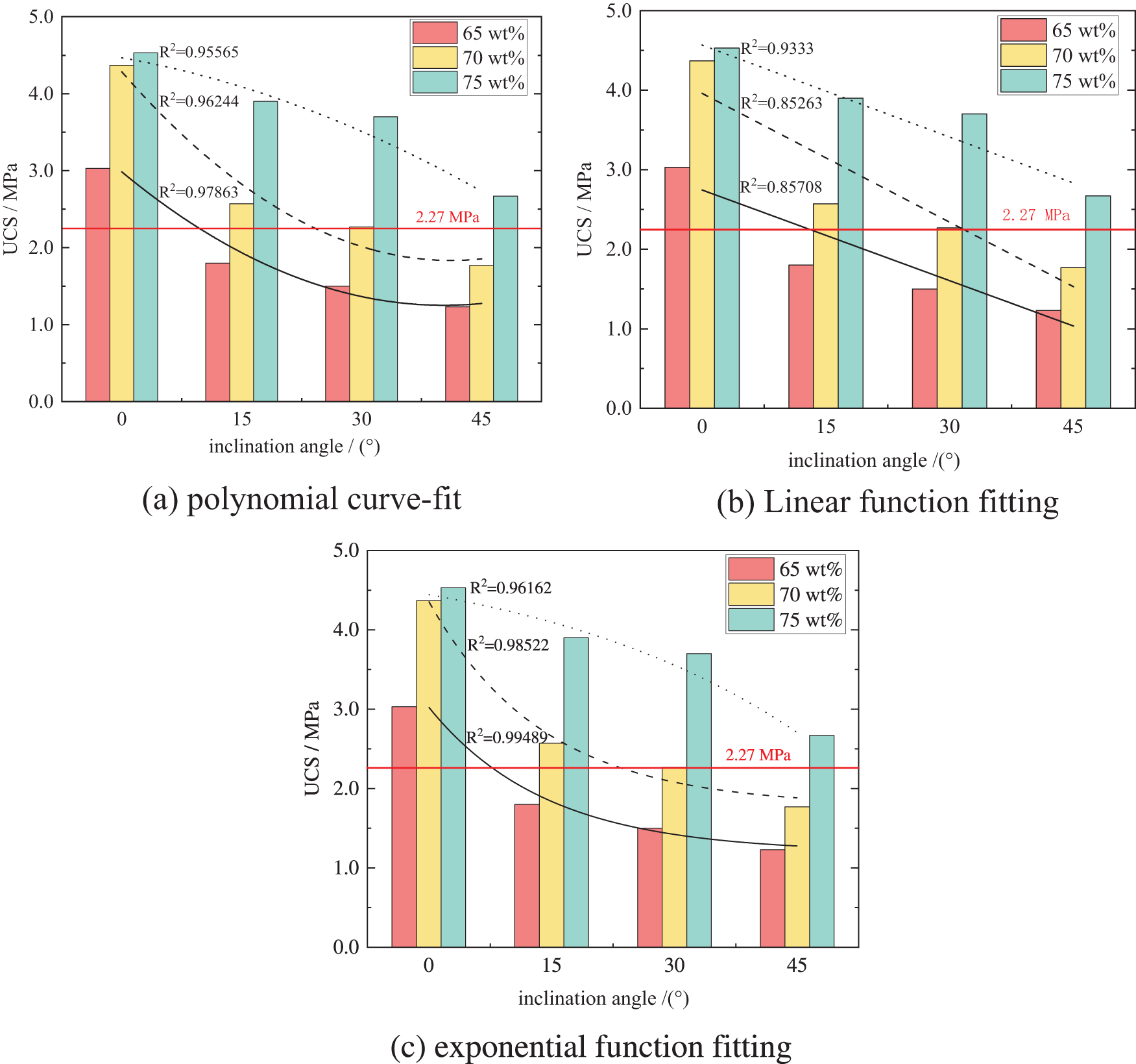
Figure 7: Fitting relationship between uniaxial compressive strength and angled backfill
The failure specimen of the horizontal LCTB was shown in Fig. 8. By analyzing the failure modes of backfill specimens with different layers in Fig. 8, it was found that the complete backfill specimens were mainly in the form of through-tensile failure and half-through-shear failure cracks parallel to the loading direction. The failure of the two and three layers backfill was mainly in the form of shear failure of the upper LCTB near the loading end, and some cracks occur through the slicing plane. For the four layers backfill, the failure mode of the specimen after loading is mainly shown as tensile failure through the delamination surface, which is more severe than that after loading.
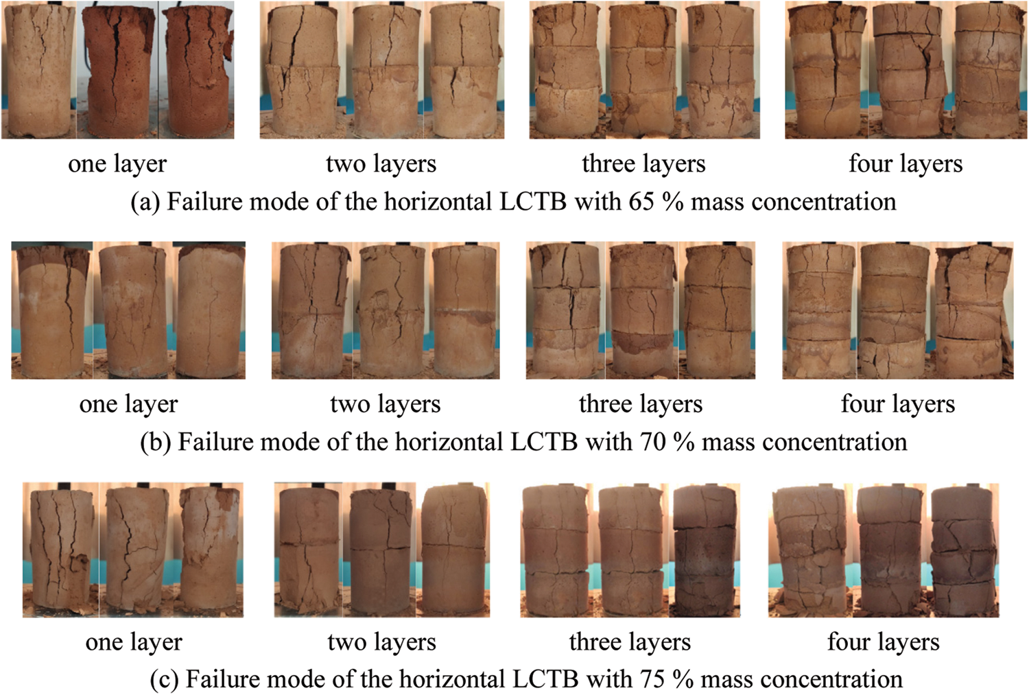
Figure 8: The failure mode of horizontal LCTB
Failure specimens of angled LCTB were shown in Fig. 9. After loading, the failure of most angled LCTB specimens mostly occurred in the upper part of the backfill, mainly in the form of longitudinal cracking. Most of the lower backfill remained intact. With the increase in inclination angle, the phenomenon of dislocation and separation between the layers is gradually intensified. According to the analysis, due to the different inclination angles of the LCTB, the larger the inclination angle, the more serious the damage to the backfill and the more serious the separation dislocation phenomenon. Therefore, the angle factor has a great influence on the overall strength of backfill.
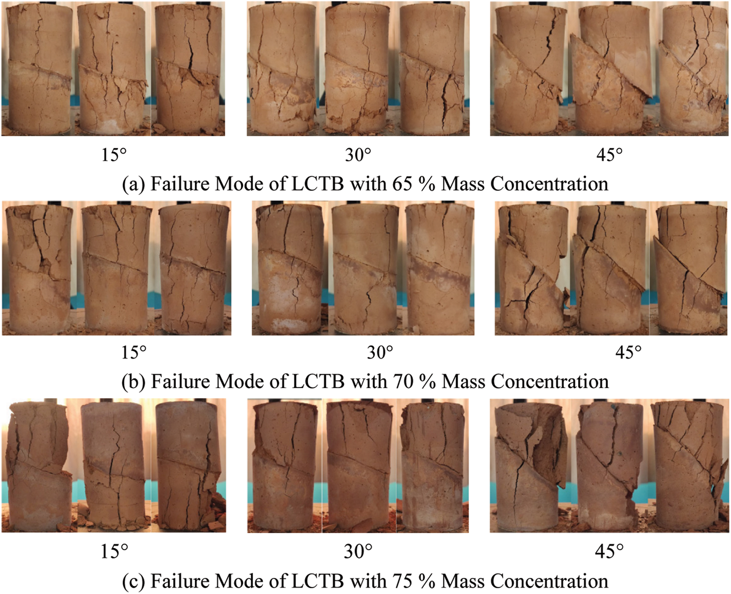
Figure 9: The failure mode of angled LCTB
A comprehensive analysis of the failure modes of the horizontal LCTB with a different number of layers and the backfill with different inclination angles shows that the upper backfill lags behind the lower backfill and the strength of the upper backfill are less than that of the lower backfill in the 28 d curing period. After loading, different degrees of separation and dislocation occurred in the LCTB specimen, and the impact of separation dislocation caused by angle factors was far greater than that of the number of layers. Delamination factors lead to the formation of low-strength interlayer in layers, which is easy to be destroyed when loading tests are carried out, which reduces the overall strength of the backfill and leads to the separation and dislocation phenomenon in different degrees at the layers of the damaged specimen, which reasonably explains the weakening effect of the compressive strength of the LCTB.
3.5 Strength Reduction Law of Filling Body under Layered Characteristics
According to the analysis of the results obtained in the above chapters, it can be seen that there is a polynomial function relationship between the strength of the filling body and the number of layers, and the strength gradually decreases with the increase of the number of layers. The strength of backfill decreases exponentially with the increase of stratification angle. The strength reduction coefficient of horizontally layered backfill is 0.560–0.932, and that of inclined layered backfill is 0.338–0.772; Combined with the analysis of the failure characteristics of layered backfill, it can be seen that the failure forms of horizontally layered backfill are mainly semi-penetrating shear failure and the failure of middle weak layer, while the failure of angle layered backfill specimen is mainly the oblique crack penetrating the upper layer. Generally speaking, the weakening effect of horizontally layered backfill is lower than that of inclined layered backfill, and horizontally layered backfill has good integrity when it is destroyed.
4 Meso-Numerical Simulation of Fracture of LCTB
Particle discrete element was a numerical method to analyze the mechanical behavior of discontinuous media. PFC was an effective tool to simulate complex problems in solid mechanics and particle flow. The size and scheme of the model simulated in this paper were consistent with the size and scheme of the laboratory test specimen. The numerical calculation model was a rectangle with a length of 100 mm and a width of 50 mm. Regardless of slurry mass concentration and curing age, only the number of layers and inclination angle on the mechanical characteristics of backfill were analyzed. Firstly, tailing particles with certain porosity are randomly formed in the rectangle according to the corresponding gradation, and then a certain number of cemented particles were randomly generated in the gap between tailing particles. To simplify the calculation, the particle radius was uniformly enlarged by 10 times. The radius of the tailings particle was 4.1 × 10⁻⁴ m∼1.5 × 10⁻³ m, and the radius of the cemented particle was 3 × 10⁻⁴ m, which was slightly smaller than that of the tailings particle. The parallel bond model was adopted for tailings particles and cementing materials. The parallel bond model could simulate the attached cementing substance between two adjacent particles. The contact between different sub-layers of the backfill body adopts smooth joint contact, as shown in Fig. 10. In the process of numerical calculation, the external force is applied to the model only by loading the wall up and down. The meso-mechanical parameters of each model are shown in Table 3.
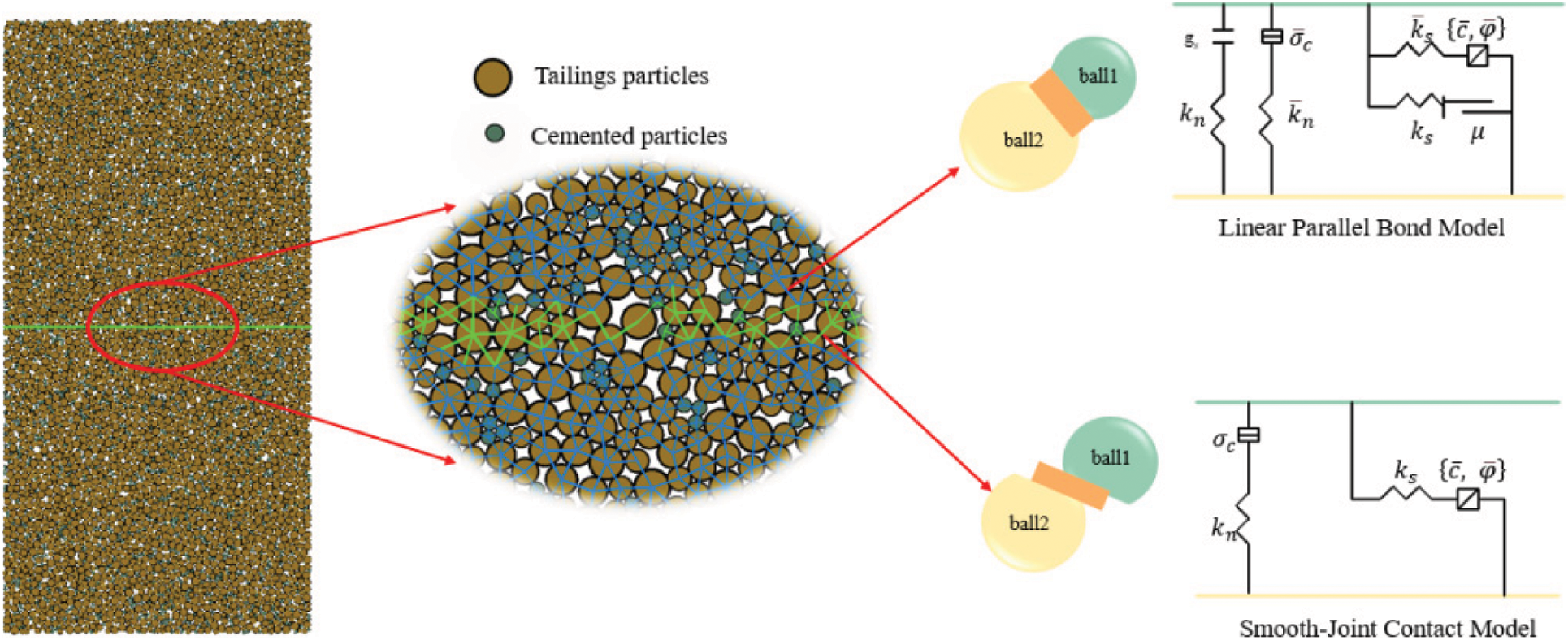
Figure 10: Numerical calculation model of horizontal LCTB with two layers

4.1 Failure Scenarios Analysis
Fig. 11 shows the numerical calculation results of failure modes of horizontal LCTB. Comprehensive analysis shows that the specimen of LCTB mainly exhibits tensile failure. When the cement-sand ratio is fixed, the internal crack density decreases with the increase in the number of layers. The internal cracks are concentrated in the soft layer and there is an obvious weakening effect in the layer. The results of the numerical calculation are basically in agreement with the failure condition of the laboratory test, which proves the feasibility of numerical calculation. The surface layer of each layered specimen was exfoliated to a certain extent. Compared with the complete filling sample, the increase of layers makes the cracks of the sample more dispersed, that is, the overall connectivity of the sample is lower. It can be seen from Fig. 11 that the particle displacement of the sample under the wall load is stratified. The closer to the two ends, the greater the displacement and decrease inward in turn.
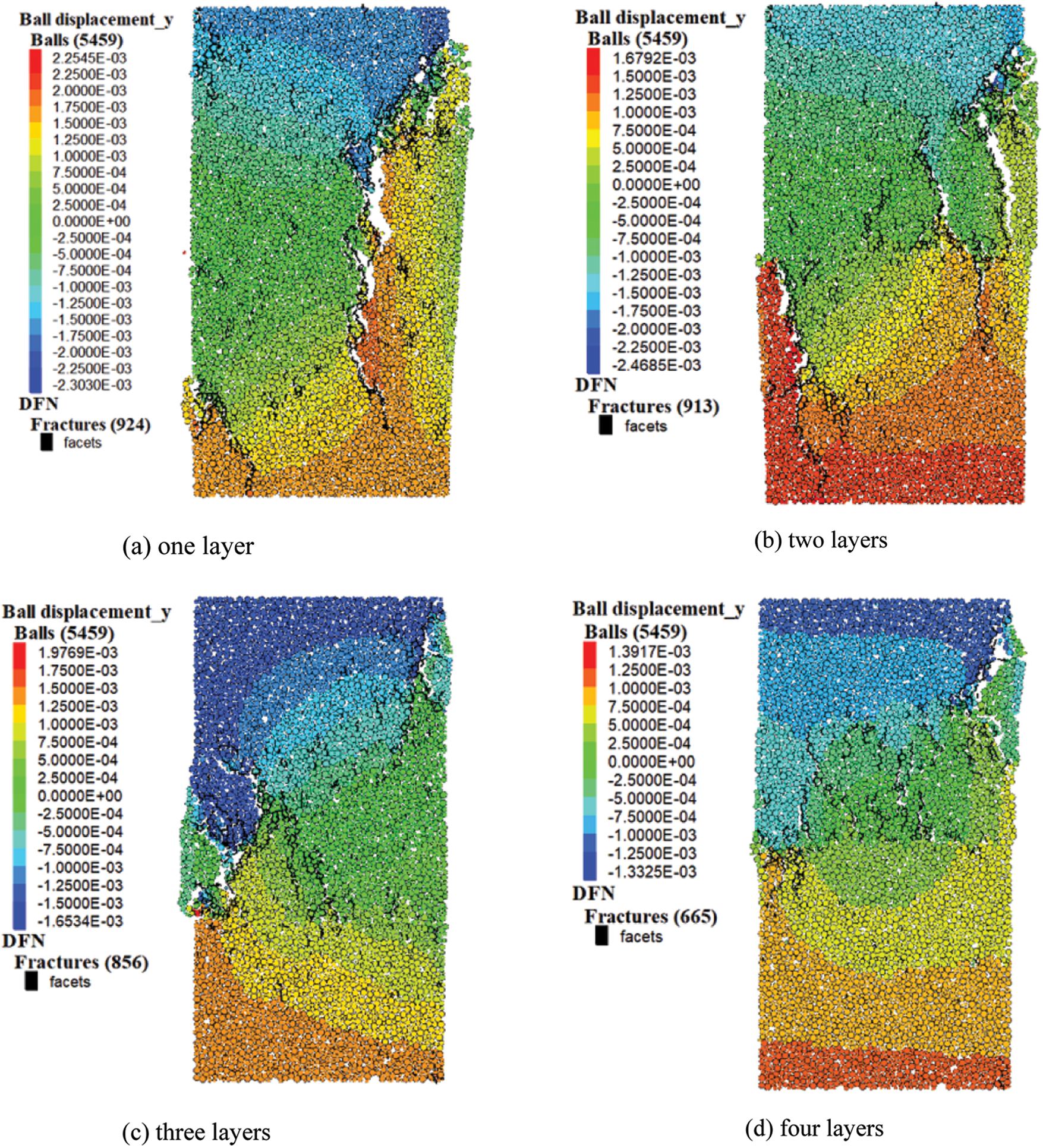
Figure 11: Failure mode and particle displacement of horizontal LCTB model
Fig. 12 shows the failure mode of angled LCTB. The internal cracks are mainly concentrated near the layered plane. With the increase of inclination angle, the crack distribution density increases, and the failure phenomenon becomes more obvious. To reflect the sliding of the upper and lower backfill based on the structural plane, the transverse displacement of particles is selected as a reference. The slip generated by the upper and lower backfill increases with the increase of inclination angle.
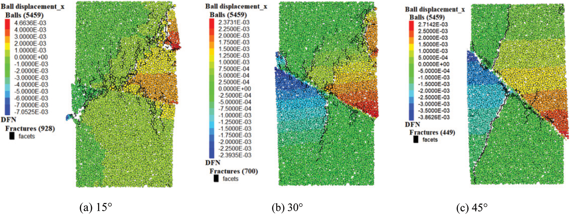
Figure 12: Failure mode and particle displacement of the angled LCTB model
By comparing and analyzing Figs. 8 and 9 with Figs. 11 and 12, it can be found that a half through tensile crack parallel to the loading direction occurs when the complete backfill model is broken; The failure of the layered filling body model with 3 and 4 times of filling is mainly the failure of the weak layer in the middle layer, and the upper and lower layered filling bodies maintain certain integrity; However, the failure of the inclination angle LCTB model often produces cracks near the vertical layered interface, and the numerical simulation results of the LCTB are basically consistent with the failure conditions of the laboratory experiments.
4.2 Distribution of Force Chain Network
The granular material is mainly densely arranged, and the contact between adjacent particles forms many external load transfer paths, which are usually quasi-linear chain structures, called force chains. The complex mechanical response of the force chain network determines the macroscopic mechanical properties of the granular system. PFC was used to obtain the force chain network after the failure of the backfill model, as shown in Fig. 13. The tailing particles are extruded to form a contact network under the action of external load. The force on the particles in the contact network is different, that is, the share of external load transferred is different so that the contact between the contact particles is strong or weak. The path that transmits a larger share of load forms a strong chain, and the other way forms a weak chain. The force chain is based on the skeleton, which further reflects the response of particles to external loads by showing the magnitude of the force.
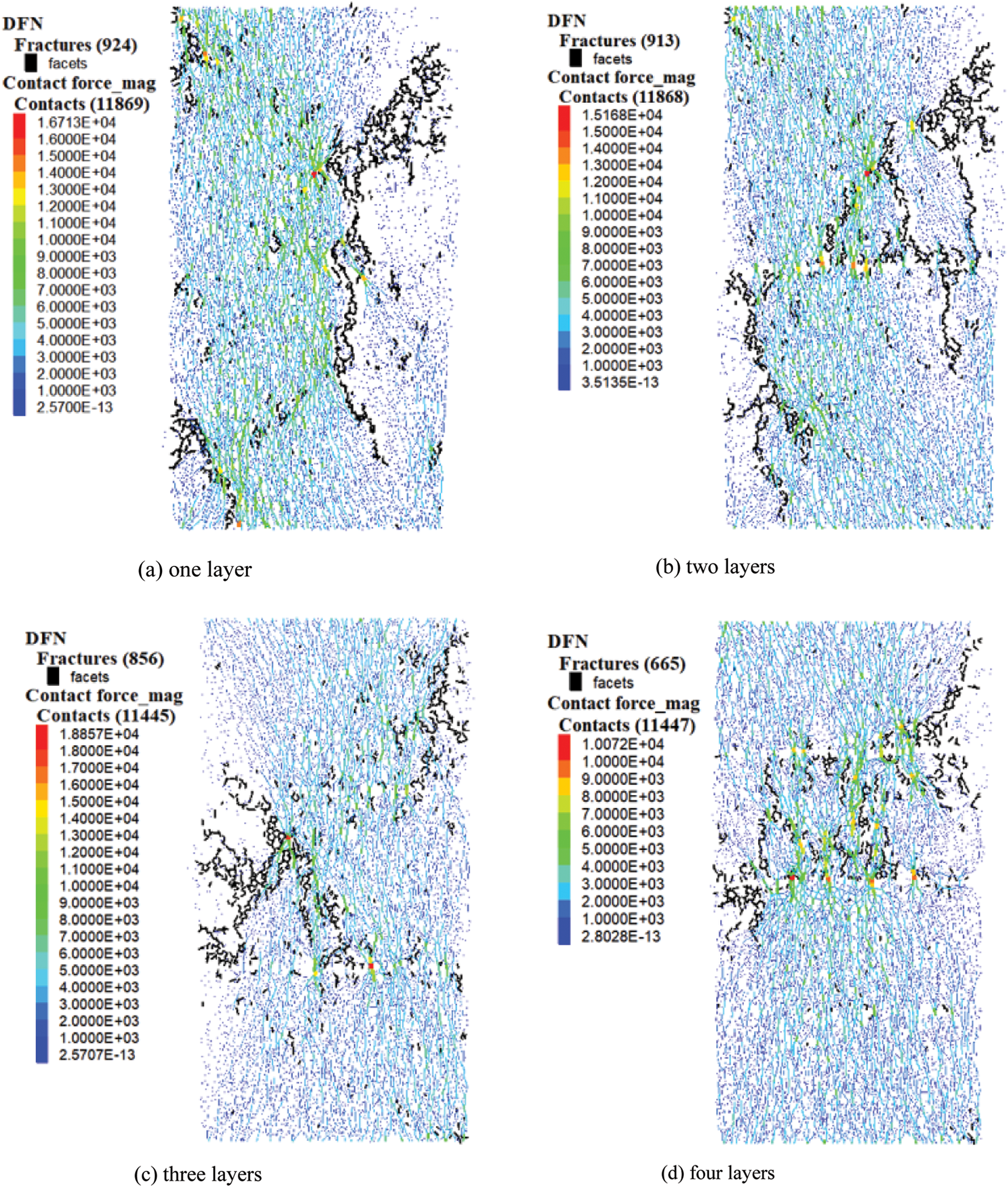
Figure 13: Composite diagram of force chain and crack distribution after the failure of horizontal LCTB
Fig. 13 shows that the expansion of cracks inside the backfill is accompanied by the phenomenon of concentration of intergranular force. After the complete backfill is destroyed, the matrix integrity is still maintained so that the particles are subjected to uniform force, and the stress concentration only appears at the crack. With the increase in the number of horizontal layers, the interlayer particles of the backfill bear a larger force and crack initiation. The crack propagation in the middle layer leads to the failure of the middle layer, and the force cannot be transferred down well. Therefore, for multilayer backfill, its failure often occurs in the middle weak layer, while the bottom layer maintains certain integrity.
Fig. 14 shows the force chain network of angled LCTB after failure. Due to the existence of a delamination interface, the direction of the backfill force chain changes significantly. When the inclination angle is 15°, the force concentration phenomenon mainly occurs at the structural plane, and the backfill force chain distribution is relatively uniform in the upper and lower layers. With the increase of inclination angle, the more obvious the macroscopic failure crack is, the lower the integrity of the sample is. The more obvious the force concentration is, the lower the residual strength is.
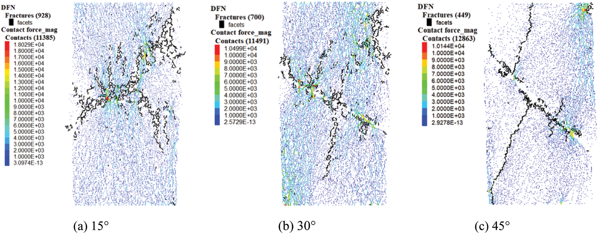
Figure 14: Composite diagrams of force chain and crack distribution after the failure of angled LCTB
This study is mainly based on the strength of horizontally and angularly LCTB, and the corresponding LCTB discrete element model is established. The reduction law of layered characteristics on compressive strength is analyzed, and the crack distribution characteristics of LCTB at the meso-level are studied. The conclusions are as follows:
(1) Through the uniaxial compression test of cemented tailings backfill and strength reduction, the corresponding reduction factor φ of horizontal LCTB is between 0.560–0.932, and the corresponding factor φ of angled LCTB is between 0.338–0.772. The factor gradually decreases with the increase of layer number and inclination angle, and layer number affects the compressive strength of the backfill. The more times the backfill is, the more obvious the weakening effect is, and the inclination factor has a more obvious factor effect on the strength of the backfill. According to the strength fitting analysis, the uniaxial compressive strength of the LCTB has a quadratic polynomial function with the number of layers and an exponential function with the inclination angle.
(2) There are three failure modes: shear failure, tensile failure, and conjugate shear failure. The formation of low strength interlayer reduces the overall bearing capacity of the backfill, resulting in a degree of mutual dislocation between the upper layer and the lower layer of the damaged specimen, and this phenomenon is more obvious for the angled LCTB.
(3) Based on laboratory tests and particle flow program PFC, the discrete element model is established to analyze the crack evolution law from the microscopic point of view. The bond between particles gradually destroys and forms micro-cracks following the loading, and develops into penetrating and semi-penetrating cracks with the increase of cracks, which verifies the correctness of the gathering mode of crack growth.
(4) The law of strength reduction of backfill under layered characteristics provides a theoretical reference for the strength design of goaf backfill and realizes the green disposal of mine solid waste to some extent. Cemented filling of mine goaf with tailings not only realizes the utilization of mine waste but also ensures the safety of goaf.
This paper mainly studies the influence of layered characteristics on the compressive strength of backfill under static load, but the backfill is also affected by the dynamic load in engineering applications. The next step will be to explore the mechanism of dynamic load on backfill.
Funding Statement: This work was supported by the National Natural Science Foundation of China (No. 51834001).
Conflicts of Interest: The authors declare that they have no conflicts of interest to report regarding the present study.
References
1. Wu, A. X., Wang, Y., Wang, H. J. (2015). Estimation model for yield stress of fresh uncemented thickened tailings: Coupled effects of true solid density, bulk density, and solid concentration. International Journal of Mineral Processing, 143, 117–24. DOI 10.1016/j.minpro.2015.09.010. [Google Scholar] [CrossRef]
2. Cao, S., Song, W. D., Deng, D., Lei, Y. K., Lan, J. Q. (2016). Numerical simulation of land subsidence and verification of its character for an iron mine using sublevel caving. International Journal of Mining Science and Technology, 26(2), 327–332. DOI 10.1016/j.ijmst.2015.12.020. [Google Scholar] [CrossRef]
3. Jiao, H. Z., Chen, W. L., Wu, A. X., Yu, Y., Ruan, Z. E. et al. (2021). Flocculated unclassified tailings settling efficiency improvement by particle collision optimization in the feedwell. International Journal of Minerals Metallurgy and Materials. DOI 10.1007/s12613-021-2402-3. [Google Scholar] [CrossRef]
4. Ouattara, D., Yahia, A., Mbonimpa, M., Belem, T. (2017). Effects of superplasticizer on rheological properties of cemented paste backfills. International Journal of Mineral Processing, 161, 28–40. DOI 10.1016/j.minpro.2017.02.003. [Google Scholar] [CrossRef]
5. Belem, T., Benzaazoua, M. (2008). Design and application of underground mine paste backfill technology. Geotechnical and Geological Engineering, 26(2), 147–174. DOI 10.1007/s10706-007-9154-3. [Google Scholar] [CrossRef]
6. Xiao, C., Zheng, H., Hou, X., Zhang, X. (2015). A stability study of goaf based on mechanical properties degradation of rock caused by rheological and disturbing loads. International Journal of Mining Science and Technology, 25(5), 741–747. DOI 10.1016/j.ijmst.2015.07.007. [Google Scholar] [CrossRef]
7. Yilmaz, E. (2018). Stope depth effect on field behaviour and performance of cemented paste backfills. International Journal of Mining, Reclamation and Environment, 32(4), 273–296. DOI 10.1080/17480930.2017.1285858. [Google Scholar] [CrossRef]
8. Sun, W., Wang, H. J., Hou, K. P. (2018). Control of waste rock-tailings paste backfill for active mining subsidence areas. Journal of Cleaner Production, 171, 567–579. DOI 10.1016/j.jclepro.2017.09.253. [Google Scholar] [CrossRef]
9. Rong, K. W., Lan, W. T., Li, H. Y. (2020). Industrial experiment of goaf filling using the filling materials based on hemihydrate phosphogypsum. Minerals, 10(4), 324. DOI 10.3390/min10040324. [Google Scholar] [CrossRef]
10. Miao, X. X., Zhang, J. X., Feng, M. M. (2008). Waste-filling in fully-mechanized coal mining and its application. Journal of China University of Mining and Technology, 18(4), 479–482. DOI 10.1016/S1006-1266(08)60279-5. [Google Scholar] [CrossRef]
11. Chen, Q., Zhu, L., Wang, Y. (2022). The carbon uptake and mechanical property of cemented paste backfill carbonation curing for low concentration of CO2. Science of the Total Environment, 158516. DOI 10.1016/j.scitotenv.2022.158516. [Google Scholar] [CrossRef]
12. Chen, Q., Sun, S., Liu, Y. (2021). Immobilization and leaching characteristics of fluoride from phosphogypsum-based cemented paste backfill. International Journal of Minerals, Metallurgy and Materials, 28(9), 1440–1452. DOI 10.1007/s12613-021-2274-6. [Google Scholar] [CrossRef]
13. Zhang, Q., Li, Y., Chen, Q. (2021). Effects of temperatures and pH values on rheological properties of cemented paste backfill. Journal of Central South University, 28(6), 1707–1723. DOI 10.1007/s11771-021-4728-4. [Google Scholar] [CrossRef]
14. Cavusoglu, I., Yilmaz, E., Yilmaz, A. O. (2021). Sodium silicate effect on setting properties, strength behavior and microstructure of cemented coal fly ash backfill. Powder Technology, 384, 17–28. DOI 10.1016/j.powtec.2021.02.013. [Google Scholar] [CrossRef]
15. Mohammad, H. G., Christopher, A. B. (2017). Sustainable reuse of mine tailings and waste rock as water-balance covers. Minerals, 7(7), 128. [Google Scholar]
16. Bussiere, B. (2007). Colloquium 2004: Hydrogeotechnical properties of hard rock tailings from metal mines and emerging geoenvironmental disposal approaches. Canadian Geotechnical Journal, 44(9), 1019–1052. DOI 10.1139/T07-040. [Google Scholar] [CrossRef]
17. Mangane, M., Argane, B. R., Trauchessec, R., Lecomte, A., Benzaazoua, M. (2018). Influence of superplasticizers on mechanical properties and workability of cemented paste backfill. Minerals Engineering, 116, 3–14. DOI 10.1016/j.mineng.2017.11.006. [Google Scholar] [CrossRef]
18. Xiu, Z. G., Wang, S. H., Ji, Y. C., Wang, F. L., Ren, F. Y. et al. (2021). Loading rate effect on the uniaxial compressive strength (UCS) behavior of cemented paste backfill (CPB). Construction and Building Materials, 271, 121526.1–121526.13. DOI 10.1016/j.conbuildmat.2020.121526. [Google Scholar] [CrossRef]
19. Kesimal, A., Yilmaz, E., Ercikdi, B., Alp, I., Deveci, H. (2005). Effect of properties of tailings and binder on the short-and long-term strength and stability of cemented paste backfill. Materials Letters, 59(28), 3703–3709. DOI 10.1016/j.matlet.2005.06.042. [Google Scholar] [CrossRef]
20. Deng, X. J., Zhang, J. X., Klein, B., Zhou, N., DeWit, B. (2017). Experimental characterization of the influence of solid components on the rheological and mechanical properties of cemented paste backfill. International Journal of Mineral Processing, 168, 116–125. DOI 10.1016/j.minpro.2017.09.019. [Google Scholar] [CrossRef]
21. Wu, J. Y., Jing, H. W., Yin, Q., Meng, B., Han, G. S. (2020). Strength and ultrasonic properties of cemented waste rock backfill considering confining pressure, dosage and particle size effects. Construction and Building Materials, 242, 118132. DOI 10.1016/j.conbuildmat.2020.118132. [Google Scholar] [CrossRef]
22. Wang, S., Song, X. P., Chen, Q. S., Wang, X. J., Wei, M. L. et al. (2020). Mechanical properties of cemented tailings backfill containing alkalized rice straw of various lengths. Journal of Environmental Management, 276, 111124. DOI 10.1016/j.jenvman.2020.111124. [Google Scholar] [CrossRef]
23. Wang, J., Fu, J. X., Song, W. D., Zhang, Y. F., Wang, Y. (2020). Mechanical behavior, acoustic emission properties and damage evolution of cemented paste backfill considering structural feature. Construction and Building Materials, 261, 119958. DOI 10.1016/j.conbuildmat.2020.119958. [Google Scholar] [CrossRef]
24. Cao, S., Song, W. D., Yilmaz, E. (2018). Influence of structural factors on uniaxial compressive strength of cemented tailings backfill. Construction and Building Materials, 174, 190–201. DOI 10.1016/j.conbuildmat.2018.04.126. [Google Scholar] [CrossRef]
25. Fu, J. X., Wang, J., Song, W. D. (2020). Damage constitutive model and strength criterion of cemented paste backfill based on layered effect considerations. Journal of Materials Research and Technology, 9(3), 6073–6084. DOI 10.1016/j.jmrt.2020.04.011. [Google Scholar] [CrossRef]
26. Jiao, H. Z., Wu, Y. C., Wang, H., Chen, X. M., Li, Z. et al. (2021). Micro-scale mechanism of sealed water seepage and thickening from tailings bed in rake shearing thickener. Minerals Engineering, 173, 107043. DOI 10.1016/j.mineng.2021.107043. [Google Scholar] [CrossRef]
27. Jiao, H. Z., Zhang, W. X., Yang, Y. X., Yang, L. H., Hu, K. J. et al. (2022). Pore structure evolution and seepage characteristics in unclassified tailing thickening process. Minerals, 12(2), 164. DOI 10.3390/min12020164. [Google Scholar] [CrossRef]
28. Yang, X. X., Qiao, W. G. (2018). Numerical investigation of the shear behavior of granite materials containing discontinuous joints by utilizing the flat-joint model. Computers and Geotechnics, 104, 69–80. DOI 10.1016/j.compgeo.2018.08.014. [Google Scholar] [CrossRef]
29. Yang, X. X., Jing, H. W., Tang, C. A., Yang, S. Q. (2017). Effect of parallel joint interaction on mechanical behavior of jointed rock mass models. International Journal of Rock Mechanics and Mining Sciences, 92, 40–53. DOI 10.1016/j.ijrmms.2016.12.010. [Google Scholar] [CrossRef]
30. Huang, Y. H., Yang, S. Q., Ranjith, P. G., Zhao, J. (2017). Strength failure behavior and crack evolution mechanism of granite containing pre-existing non-coplanar holes: Experimental study and particle flow modeling. Computers and Geotechnics, 88, 182–198. DOI 10.1016/j.compgeo.2017.03.015. [Google Scholar] [CrossRef]
31. Bahaaddini, M., Sharrock, G., Hebblewhite, B. K. (2013). Numerical investigation of the effect of joint geometrical parameters on the mechanical properties of a non-persistent jointed rock mass under uniaxial compression. Computers and Geotechnics, 49, 206–225. DOI 10.1016/j.compgeo.2012.10.012. [Google Scholar] [CrossRef]
32. Fan, X., Kulatilake, P. H., Chen, X. (2015). Mechanical behavior of rock-like jointed blocks with multi-non-persistent joints under uniaxial loading: A particle mechanics approach. Engineering Geology, 190, 17–32. DOI 10.1016/j.enggeo.2015.02.008. [Google Scholar] [CrossRef]
33. Cheng, C., Chen, X., Zhang, S. F. (2016). Multi-peak deformation behavior of jointed rock mass under uniaxial compression: Insight from particle flow modeling. Engineering Geology, 213, 25–45. DOI 10.1016/j.enggeo.2016.08.010. [Google Scholar] [CrossRef]
Cite This Article
 Copyright © 2023 The Author(s). Published by Tech Science Press.
This work is licensed under a Creative Commons Attribution 4.0 International License , which permits unrestricted use, distribution, and reproduction in any medium, provided the original work is properly cited.


 Submit a Paper
 Propose a Special lssue
 View Full Text
 Download PDF
 Downloads
 Citation Tools