| Journal of Renewable Materials |
DOI: 10.32604/jrm.2022.022254
ARTICLE
Numerical Simulation of Vacuum Preloading for Chemically Conditioned Municipal Sludge
1Key Laboratory of Ministry of Education for Geomechanics and Embankment Engineering, College of Civil and Transportation Engineering, Hohai University, Nanjing, 210098, China
2Geotechnical Engineering Department, Nanjing Hydraulic Research Institute, Nanjing, 210029, China
*Corresponding Author: Xinjie Zhan. Email: xjzhan@nhri.cn
Received: 06 March 2022; Accepted: 09 May 2022
Abstract: Municipal sludge is a sedimentation waste produced during the wastewater process in sewage treatment plants. Among recent studies, pilot and field tests showed that chemical conditioning combined with vacuum preloading can effectively treat municipal sludge. To further understand the drainage and consolidation characteristics of the conditioning sludge during vacuum preloading, a large deformation nonlinear numerical simulation model based on the equal strain condition was developed to simulate and analyze the pilot and field tests, whereas the simulation results were not satisfactory. The results of the numerical analysis of the pilot test showed that the predicted consolidation degree was greater than that measured by the field tests, which is attributed to the relatively low permeability layer formed during the preloading process of the prefabricated vertical drain. To better reflect the consolidation process of the conditioned sludge, a simplified analysis method considering the low permeability layer around the prefabricated vertical drain was proposed. The initial permeability coefficient of the low permeability layer is determined via numerical simulations using finite difference method. The predicted settlement curve was in good agreement with the measured results, which indicated that the numerical simulation based on the equal strain condition considering the relatively low permeability layer can better analyze the consolidation process of ferric chloride-conditioning sludge with vacuum preloading.
Keywords: Sludge treatment; large deformation; numerical simulation; chemical conditioning-combined vacuum preloading; low permeability coefficient; back analysis
Municipal sludge is a precipitate produced during municipal-sewage treatment [1–4]. It has fine particles, high moisture content, and difficult dewatering. It is a complex precipitate with a high content of organic matter and a variety of pollutants [5–10]. Current research on sewage sludge disposal focused on dewatering and subsequent solidification of sludge in sewage treatment plants. Meanwhile, dehydration and solidification of sludge in landfills are difficult and expensive [11,12].
Vacuum preloading was regarded as one of the effective methods of reinforcing foundations in areas with super soft soil [13]. Generally, it improved the load capacity and reduced settlement in airport runways, oil storage stations and land reclamation projects [14–16].
The mechanical properties of sludge [17,18] are similar to those of the ultra-soft soil, hence, in order to effectively treat sludge at low cost in sludge lagoons of municipal solid waste landfills, Lin et al. [19] proposed a two-stage method called ‘vacuum preloading combined with chemical conditioning’, which had advantages over the traditional methods. However, to date, no numerical simulation study on the consolidation characteristics of chemically conditioned sludge using this two-stage method has been reported to better understand the consolidation characteristics of chemically conditioned sludge under vacuum preloading and to popularize the process.
Shaft consolidation theory is usually employed to evaluate the consolidation deformation of soft soil foundations in vacuum preloading research. Based on Barron’s consolidation theory [20], Hansbo [21] proposed a theoretical solution considering the well resistance, smear effect, and anisotropy of soil permeability coefficients. Berry et al. [22] considered the nonlinearity of the soil and improved the solution of the classical consolidation equations with small deformation. Indraratna et al. [23] proposed a mathematical analytical formula based on the modified consolidation theory considering vacuum pressure. Tang et al. [24] enriched and improved the shaft consolidation theory by considering the non-instantaneous loading and layered characteristics. In addition, many scholars have carried out numerical studies [25,26] on different process combinations such as vacuum preloading and electroosmosis [27,28], which were helpful for the better understanding of the mechanism of reinforcement. In the above-cited studies, different compression and permeability curves were used to describe the soil, and more accurate consolidation solutions were obtained, however, the basic framework was still the small deformation consolidation.
In this study, a numerical analysis model for large deformation nonlinear shaft consolidation, which considers the large deformation and nonlinear characteristics of conditioned sludge in the consolidation process, was developed. The model was used to simulate the pilot and field tests [29] of chemically conditioned sludge under the conditions of vacuum preloading in a sludge lagoon at the Chang’an landfill, China, and the simulation results were compared with the measured values.
2.1 Basic Properties of Chemically Conditioned Municipal Sludge
The sludge used in the test was taken from Chang’an landfill in Chengdu, China, and the basic properties were shown in Table 1 below.

The compression characteristic (e–p) curve of the Chengdu conditioned sludge is shown in Fig. 1. As can be seen from the figure, the curve is piecewise linear. Based on the results of the consolidation tests, the compression characteristics of the conditioned sludge are similar to those of the untreated sludge.

Figure 1: Void ratio versus consolidation pressure (e–p) of the conditioned Chengdu sludge
The permeability coefficient vs. void ratio (k–e) curves of the infiltration characteristics of the Chengdu conditioned sludge (5% and 10% of ferric chloride added) are shown in Fig. 2. The permeability coefficient of the conditioned sludge is calculated based on the results of the consolidation tests under different pressures. At the initial state (e = 15.873), the permeability coefficient k of the Chengdu sludge is 9 × 10⁻⁷ cm/s and that of the conditioned sludge treated with 10% ferric chloride is 3 × 10⁻⁶ cm/s, which is 3.3 times that of the untreated Chengdu sludge. When the void ratio e is 3.22, the permeability coefficient k of the Chengdu sludge is 2.14 × 10⁻⁹ cm/s and that of the conditioned sludge treated with 10% ferric chloride is 4.72 × 10⁻⁹ cm/s, which is 2.2 times that of the untreated Chengdu sludge.
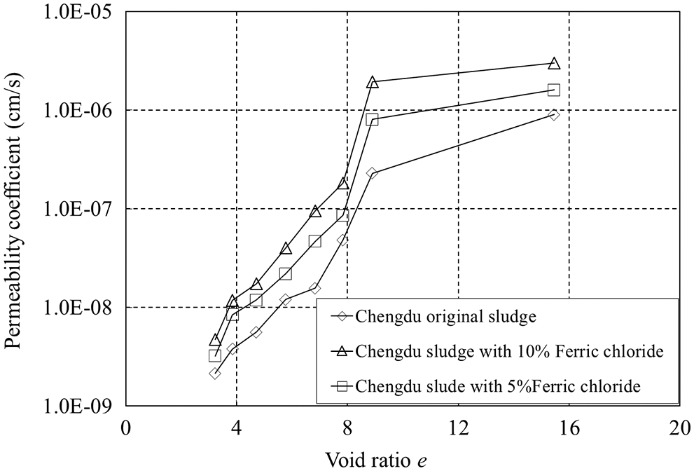
Figure 2: Permeability coefficient–void ratio (k–e) of the conditioned and untreated Chengdu sludge
As shown in Fig. 2, the curves of the Chengdu conditioned sludge treated with 5% and 10% ferric chloride are also piecewise linear. When the void ratio of the sludge is higher than 8, the permeability coefficient tends to vary linearly with the void ratio, which is consistent with the permeability characteristics of super soft soil reported by Myint Win et al. [30]. Based on the above consolidation test results of the conditioned sludge, the e–p and k–e curves are both piecewise linear.
3 Theoretical Model and Numerical Simulation
The numerical model based on the large deformation nonlinear shaft consolidation theory proposed by Fox et al. [31] is used to analyze the soil consolidation of foundation improved by the prefabricated vertical drain. In this model, the radially consolidated soil layer is discretized into a series of annular units, and the vacuum pressure is applied to the boundary of the prefabricated vertical drain as a fixed excess pore pressure.
The grid diagram of the model is shown in Fig. 3. The unit height of the numerical model is H0. Ri and Rj are the total number of radial units and vertical units, respectively. At the initial moment, the cross section of each annular element is rectangular with a width of Δri and a height of

Figure 3: Diagram of model of vacuum preloading combined with PVD for Chengdu sludge
After seepage, the unit is deformed, and its deformation only occurs in the vertical direction. The unit width remains unchanged after deformation, and the shape of the deformed unit is trapezoid. The upper right corner of the radial outermost mesh is still rectangular after deformation, which can ensure that there is no shear deformation on the horizontal boundary and make the numerical close. In the process of sludge layer deformation, the average height of the unit ij and the grid center ztijare calculated according to the following formulas:
In the formula:
where Vtij is the unit volume at time t. Since the radial outermost grid is rectangular, the coordinates of the upper right corner of the deformed grid are actually calculated from the right to the left.
3.2 Nonlinear Numerical Simulation Model for Large Deformation
Fox et al. [31] proposed a numerical model based on the large deformation nonlinear shaft consolidation theory. In the model, the compression characteristic and permeability coefficient curves of the soil are divided into piecewise linear, which makes the simulation analysis more flexible. Herein, the nonlinear numerical simulation model for large deformation of shaft foundations under the condition of equal strain is compiled by the FORTRAN programing language. The detailed calculation process of the parameters is based on the reference [31]. The specific calculation steps of the model are shown in Fig. 4.

Figure 4: Specific calculation steps of the developed model
The total stress of the unit
The pore pressure of the unit can be derived as:
The hydraulic head of the unit can be derived as:
Due to the different permeability coefficients of adjacent units, the equivalent radial permeability coefficient is introduced to calculate the horizontal seepage between units. The equivalent permeability coefficients
The hydraulic gradient between adjacent units can be obtained:
The hydraulic gradient at the prefabricated vertical drain is:
where
Seepage flow between adjacent units can be calculated by the following formula:
When the flow rate at the prefabricated vertical drain is calculated,
The unit volume can be updated from the seepage flow between adjacent units after each step Δt, shown as the following formulas:
At t + Δt moment, the surface displacement of different units
where S is the final settlement of the soil layer under the vacuum load;
The time step Δt is calculated using the formula recommended by Fox et al. [31]:
where
3.3 The Verification of the Model
To verify the numerical simulation model, the obtained results are compared with those based on Barron’s consolidation theory as recorded by Fox et al. [31]. The upper and lower surfaces of the soil layer are impervious and there is only radial drainage. The Barron’s consolidation theory is based on the assumption of small deformation, hence, the vacuum pressure dq in the prefabricated vertical drain is set to 0.1 kPa in the numerical simulation to avoid the large deformation generation and ensure the accuracy of Barron consolidation theory. The degree of consolidation is calculated based on the settlement conversion. When the load applied to the soil is small, the nonlinear numerical simulation results for large deformations based on equal strain are consistent with the results based on Barron’s consolidation theory.
Fig. 5 compares the results obtained herein with those based on Barron’s consolidation theory. The Figure indicates that the two results are very close and the model developed is validated herein.

Figure 5: Comparison of the results of the developed model and those based on the Baron’s consolidation theory
Indraratana et al. [23] derived the formula for the degree of consolidation of shaft foundations considering the nonlinearity of the soil material, which can take into account the nonlinear consolidation of shaft foundations. When the soil has large vertical deformation and constant strain, the soil permeability coefficient and the void ratio decrease but the seepage path in the horizontal direction remains unchanged and the changes in each radial element are the same, which implies that there is only material nonlinearity in the consolidation process and no geometric nonlinearity. Therefore, the nonlinear numerical simulation results of large deformations based on equal strain should be consistent with those based on nonlinear shaft consolidation theory [23]. The results recorded by Fox et al. [31] as an example of numerical simulation results based on the equal strain are compared with those based on the nonlinear shaft consolidation theory, as shown in Fig. 6.

Figure 6: Comparison of the numerical simulation results based on the equal strain and those based on the nonlinear shaft consolidation theory
The two results are consistent, which further validates the model developed herein. It is noteworthy that the nonlinear consolidation theory of shaft foundation proposed by Indraratna et al. [23] is an analytical solution, which is suitable for solving the case that the e–p curve and e–k curve are linear in the whole section. The consolidation test results showed that the e–p curve and e–k curve of chemically conditioned municipal sludge are piecewise linear, hence, the Indraratna’s solution is not applicable.
Lin et al. [19] proposed a two-stage in-situ treatment method for vacuum preloading on conditioned sludge combined with chemical treatment to improve the sludge ground. Based on the pilot and field tests [19,29], it was proven that the combination of vacuum preloading and chemical treatment can successfully reduce the amount of sludge treatment, and a good curing effect was obtained. To further understand the consolidation characteristics of the conditioned sludge in the treatment process, the field and pilot tests were simulated with the developed model and the results were compared with the measured values.
4.1 Numerical Simulation of the Pilot Test and the Field Test
In the pilot test, an equal amount of ferric chloride (10%) was added along the depth (3.2 m). Owing to the good sealing effect, the vacuum pressure under the film was 80 kPa and the vacuum negative pressure along the depth was −80 kPa. The field test results revealed that the vacuum load was evenly distributed along the integral plastic prefabricated vertical drain, there was no loss in load transfer and no well resistance effect. At the same time, due to the remolding of sludge, the smear effect was not considered. The prefabricated vertical drains were arranged in a square form with a spacing of 0.4 m, and the equivalent diameter dw of the processing unit of the prefabricated vertical drain was 0.45 m. The basic parameters for the numerical analysis of the pilot test are listed in Table 2.

Fig. 7 gives the comparison between the numerical simulation result and the measured result of the pilot test.
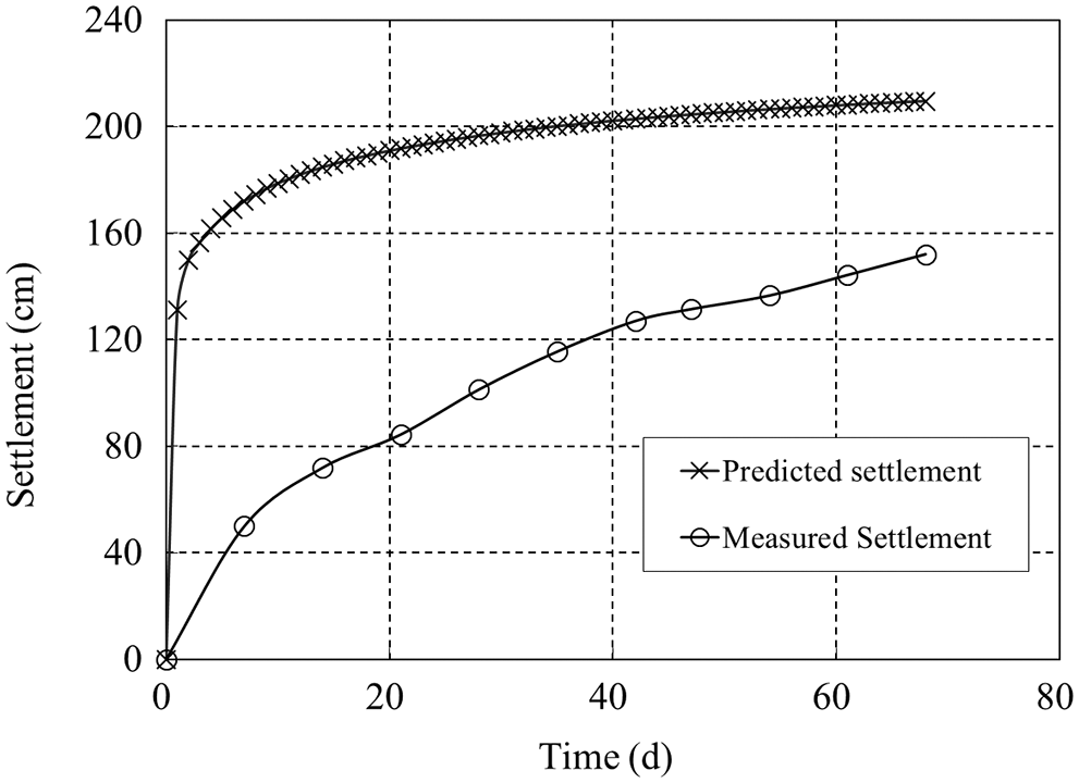
Figure 7: Comparison between the simulation and the measured results of the pilot test
Based on the results of the field test [19,29], the optimum ferric chloride addition was 7.5% and 5% for the depths of 0–3 and 3–7 m, respectively. The e–k curve of the conditioned sludge treated with 5% ferric chloride can be obtained directly from Fig. 2. On the other hand, the permeability coefficient k of the conditioned sludge with 7.5% ferric chloride can be obtained based on the compression characteristics from the average permeability coefficient of the conditioned sludge treated with 10% and 5% ferric chloride. The results of the vacuum test under a membrane revealed that the vacuum negative pressure in the prefabricated vertical drain was −60 kPa for 0–85 d and −20 kPa for 85–114 d. The prefabricated vertical drains were arranged in a square form with a spacing of 0.4 m, thus, the equivalent diameter of the processing unit of the prefabricated vertical drain is 0.45 m. The basic parameters for the numerical simulation analysis of the field test are listed in Table 3.

The numerical simulation results and the measured results are compared in Fig. 8.

Figure 8: Comparison between the numerical simulation results and the measured results
As shown in Figs. 7 and 8, the predicted settlement obtained based on the model developed is much higher than the corresponding measured settlement. This was attributed to the fact that the numerical simulation model based on equal strain assumed that the deformation of the radial grid is consistent. The changes in the water content and permeability coefficient of the sludge at different positions of the radial distance from the prefabricated vertical drain were the same. Although the developed model can better simulate the successive changes in the water content of the sludge around the prefabricated vertical drain as well as the “overall vertical deformation” of the sludge layer, it was assumed that there was a greater arch effect on the soil surface. The stress on each element around the prefabricated vertical drain was redistributed after deformation and that on each element near the prefabricated vertical drain decreases, whereas that on each element far away from the prefabricated vertical drain increases. Also, the deformation of each element was consistent but it was different from the actual deformation. In the actual vacuum preloading process, the sludge near the prefabricated vertical drain was consolidated first and the water content decreased, thereby forming a relatively low permeability layer, which slowed down the whole drainage consolidation process [32]. At the same time, due to the interaction between the sludge units, the sludge around the prefabricated vertical drain settled one after the other, and the actual deformation of the sludge layer was closer to that based on equal strain. Therefore, the model developed herein is also based on equal strain condition.
4.2 Numerical Simulation Considering Low Permeability Layer
By comparing the sludge vacuum preloading test and the numerical simulation results, a certain difference was observed between the numerical simulation results and the measured results. The reason for the difference was that in the actual vacuum preloading process, the sludge was first consolidated near the prefabricated vertical drain. The decrease in the water content resulted in a relatively low permeability layer. This phenomenon of low permeability layer was also observed in the vacuum preloading process of the dredged fill with high water content [32]. Due to the high water content of the conditioned sludge, the soil particles were in a fluid state. Then, a large hydraulic gradient was created between the prefabricated vertical drain and the sludge under the vacuum pressure and some of the fine particles formed a soil column around the prefabricated vertical drain.
To better simulate the effect of the relatively low permeability layer around the prefabricated vertical drain on the drainage consolidation during sludge preloading, the following simplified analysis is performed. It is assumed that the low permeability layer is rapidly formed in the preloading process, which is similar to the smeared area in sand well foundations. At the initial time, the radius of the permeability layer is rs, which is equal to the equivalent diameter of prefabricated vertical drain de, and the permeability coefficient of the sludge outside the layer kh is m times higher than the permeability coefficient of the sludge in the low permeability layer ks
To analyze the selection of the ratio of the permeability coefficient of the sludge outside the layer to that of the sludge in the low permeability layer, a numerical model for vacuum preloading of the conditioned sludge considering the low permeability layer was established using the finite difference method, and the pilot and field tests were simulated, respectively (as shown in Fig. 9).

Figure 9: Numerical model for vacuum preloading of the conditioned sludge for pilot and the field tests
In the model, the radius of the low permeability layer is three times the equivalent radius of the prefabricated vertical drain, and to more realistically simulate the consolidation process, the permeability coefficient changed based on the e–p and k–e curves for the Chengdu conditioned sludge during the simulation.
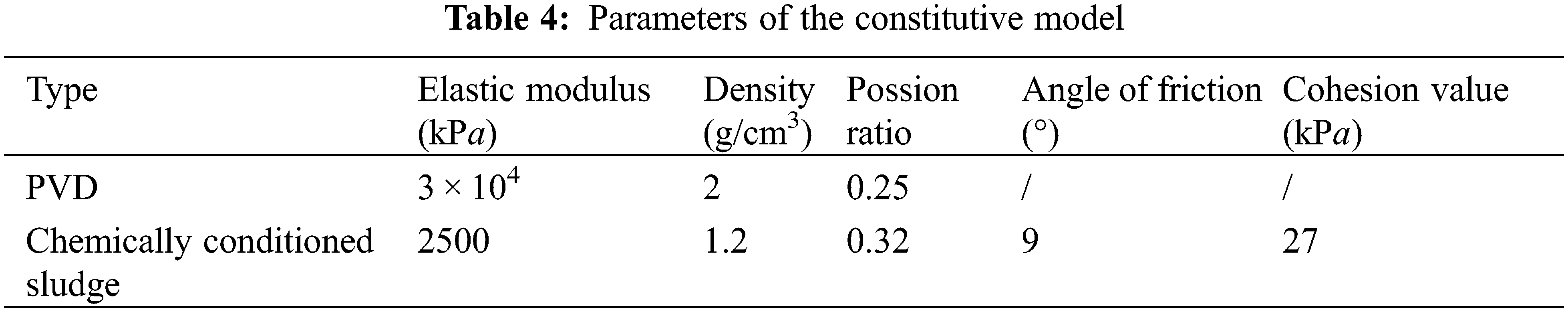
The constitutive model for the chemically conditioned sludge is the Drucker–Prager model and that of the PVD is the elastic–plastic model. Because the strength of sludge prior to solidification is low, the mechanical parameters cannot be obtained directly by strength tests. Therefore, the parameters of the constitutive model were obtained by inversion. The main parameters of the model are listed in Table 4.
The kh/ks ratios for the various numerical simulations were set at 10, 20, 30, and 40, respectively, and the settlement–time curves of the pilot and field tests at different ratios were compared with the measured results, as shown in Figs. 10 and 11.

Figure 10: Comparison between the measured settlement and the settlement predicted with different ratios in the pilot test

Figure 11: Comparison between the measured settlement and the settlement predicted with different ratios in the field test
As shown in Figs. 10 and 11, when the kh/ks ratio is less than 40, the values of the final settlement obtained from the simulation of the pilot and field tests are significantly higher than the measured value. When the ratio is 40, the values of the final settlement are in good agreement with the measured value, and the increasing trends are similar. Therefore, it can be assumed that the consolidation process of conditioned sludge can be better simulated at a ratio of 40.
4.3 Numerical Simulation Based on the Established Method
The permeability coefficient, void ratio, and water content of the Chengdu conditioned sludge are listed in Table 5. When the water content of the sludge was reduced from 860% to 435%, the permeability coefficient decreased by 15 times, and when it was further reduced to 380%, the permeability coefficient decreased by about 30 times. Hence, the permeability coefficient of sludge decreased significantly with a decrease in the water content. According to simulation results based on finite difference method, kh/ks = 40 was used for the back analysis of the consolidation process.

The setting of the numerical simulation is the same as that of the numerical simulation based on finite difference method. The back-analysis results of the numerical simulation are shown in Figs. 12 and 13. When rs/rw = 3 and kh/ks = 40, the measured results of the field and the pilot tests are in good agreement with those of the numerical simulation. This proves that the numerical simulation model based on the equal stain condition considering the relative low permeability layer can efficiently analyze the consolidation process of the conditioned sludge treated with ferric chloride during the vacuum preloading process.

Figure 12: Comparison between the measured settlement and the back analysis of numerical simulation in the pilot test
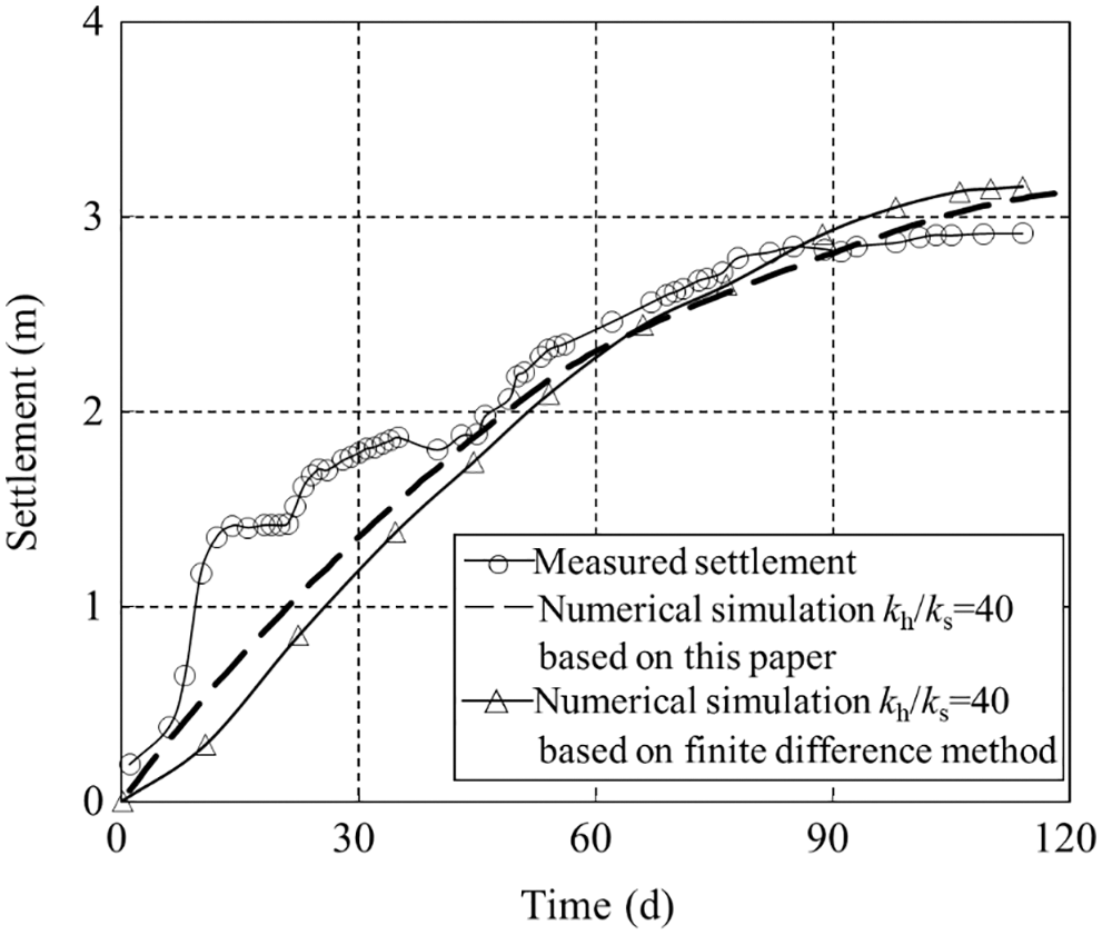
Figure 13: Comparison between the measured settlement and the back analysis of numerical simulation in the field test
Based on the ‘vacuum preloading combined with chemical conditioning’, a large-deformation consolidation analysis model was developed to simulate the consolidation settlement of the conditioned sludge in the pilot and field tests. The back analysis was also performed under the assumption of the low permeability layer. The main conclusions are as follows:
(1) Under the same condition, the predicted settlement simulated by the developed model is in good agreement with Barron’s solution as well as the nonlinear solution, which indicates that it is feasible to use the large-deformation theory to simulate the consolidation process of chemically conditioned sludge.
(2) The results of the pilot and field tests show that the settlements predicted by the numerical simulation model based on the equal strain condition are much higher than the measured values.
(3) During the vacuum preloading of sludge, the sludge near the prefabricated vertical drain was first consolidated and the water content decreased, thereby forming a relatively low permeability layer, and thus, the whole consolidation process is prolonged. Therefore, to better simulate the process of chemically conditioned sludge consolidation, the effect of the low permeability layer should be considered.
(4) The simulation of the vacuum preloading of conditioned sludge considering the low permeability layer was performed based on the finite difference method. It is concluded that a kh/ks ratio of 40 can better simulate the consolidation characteristics of conditioned sludge under vacuum preloading treatment.
(5) Considering the low permeability layer formed around the prefabricated vertical drain, the pilot and field tests for the vacuum preloading of conditioned sludge were analyzed using the numerical simulation model developed herein. The obtained results are in good agreement with the measured results as well as those simulated using the finite difference method.
Funding Statement: The authors would like to acknowledge the financial support from The National Natural Science Foundation No. Gk321002, Foundation of Nanjing Hydraulic Research Institute No. Y320012.
Conflicts of Interest:The authors declare that they have no conflicts of interest to report regarding the present study.
References
1. Wang, H., Xu, J., Liu, Y., Sheng, L. (2021). Preparation of ceramsite from municipal sludge and its application in water treatment: A review. Journal of Environmental Management, 287, 112374. DOI 10.1016/j.jenvman.2021.112374. [Google Scholar] [CrossRef]
2. Jiang, G., Xu, D., Hao, B., Liu, L., Wang, S. et al. (2021). Thermochemical methods for the treatment of municipal sludge. Journal of Cleaner Production, 311, 127811. DOI 10.1016/j.jclepro.2021.127811. [Google Scholar] [CrossRef]
3. Wu, Y., Zhang, X., Zhang, X., Xu, Y., Zhang, H. (2021). Novel insights into enhanced dewaterability and consolidation characteristics of landfill sludge and fresh sludge conditioned by Fe2+ activated sodium persulfate. Journal of Environmental Management, 296, 113196. DOI 10.1016/j.jenvman.2021.113196. [Google Scholar] [CrossRef]
4. Zhan, X. J., Zhan, L. T., Lin, W. A., Chen, Y. M. (2021). Moisture distribution in sewage sludge based on soil-water characteristic curve. Chinese Journal of Geotechnical Engineering, 43(11), 2112–2118. [Google Scholar]
5. Lo, M., Zhou, W. W., Lee, K. M. (2002). Geotechnical characterization of dewatered sewage sludge for landfill disposal. Canadian Geotechnical Journal, 39(5), 1139–1149. DOI 10.1139/t02-058. [Google Scholar] [CrossRef]
6. O’Kelly, B. C. (2018). Geotechnical laboratory testing and data interpretation for biosolids and sewage sludge. Geotechnical Research, 5(4), 247–261. DOI 10.1680/jgere.18.00009. [Google Scholar] [CrossRef]
7. Zhan, T. L., Zhan, X., Lin, W., Luo, X., Chen, Y. (2014). Field and laboratory investigation on geotechnical properties of sewage sludge disposed in a pit at Chang’an landfill, Chengdu, China. Engineering Geology, 170, 24–32. DOI 10.1016/j.enggeo.2013.12.006. [Google Scholar] [CrossRef]
8. Taki, K., Choudhary, S., Gupta, S., Kumar, M. (2020). Enhancement of geotechnical properties of municipal sewage sludge for sustainable utilization as engineering construction material. Journal of Cleaner Production, 251, 119723. DOI 10.1016/j.jclepro.2019.119723. [Google Scholar] [CrossRef]
9. Rafael, D. M. P., Costa, C. M. L., Costa, Y. D. J. (2017). Geotechnical study on the use of sanitized sewage sludge in cover layers of solid waste landfills. Applied Mechanics and Materials, 872, 143–148. DOI 10.4028/www.scientific.net/AMM.872.143. [Google Scholar] [CrossRef]
10. Chen, Y., He, X., Wang, P., Wan, Y., Tan, X. (2020). Experimental study of moisture content effect on geotechnical properties of solidified municipal sludge. Advances in Polymer Technology, 2020(6), 1–10. DOI 10.1155/2020/8794076. [Google Scholar] [CrossRef]
11. Wu, Y., Wang, Y., Zhang, X., Zhang, Y., Zhang, X. et al. (2022). Freeze-thaw vacuum treatment of landfill sludge: Mechanism of uneven frost heaving and dewatering performance. Science of the Total Environment, 815, 152930. DOI 10.1016/j.scitotenv.2022.152930. [Google Scholar] [CrossRef]
12. Ray, S., Mishra, A. K., Kalamdhad, A. S. (2022). Hydraulic performance, consolidation characteristics and shear strength analysis of bentonites in the presence of fly-ash, sewage sludge and paper-mill leachates for landfill application. Journal of Environmental Management, 302, 113977. DOI 10.1016/j.jenvman.2021.113977. [Google Scholar] [CrossRef]
13. López-Acosta, N. P., Espinosa-Santiago, A. L., Pineda-Núez, V. M., Ossa, A., Mendoza, M. J. et al. (2019). Performance of a test embankment on very soft clayey soil improved with drain-to-drain vacuum preloading technology. Geotextiles and Geomembranes, 47(5), 618–631. DOI 10.1016/j.geotexmem.2019.103459. [Google Scholar] [CrossRef]
14. Wang, J., Zhou, Z., Fu, H., Dong, Q. Y., Hu, X. Q. (2018). Influence of vacuum preloading on vertical bearing capacities of piles installed on coastal soft soil. Marine Georesources & Geotechnology, 37(1), 1–10. DOI 10.1080/1064119X.2018.1424971. [Google Scholar] [CrossRef]
15. Fu, H., Wang, J., Cai, Y., Jin, J. Q., Zhang, D. K. (2020). Field study of monotonic and cyclic lateral behaviour of piles in soft soils improved with and without vacuum preloading. Acta Geotechnica, 15(12), 3183–3192. DOI 10.1007/s11440-020-00935-7. [Google Scholar] [CrossRef]
16. Li, J., Chen, H., Yuan, X., Shan, W. (2020). Analysis of the effectiveness of the step vacuum preloading method: A case study on high clay content dredger fill in Tianjin, China. Journal of Marine Science and Engineering, 8(1), 38. DOI 10.3390/jmse8010038. [Google Scholar] [CrossRef]
17. Liu, F. Y., Wu, W. Q., Fu, H. T., Wang, J., Lou, X. M. (2019). Application of flocculation combined with vacuum preloading to reduce river-dredged sludge. Marine Georesources & Geotechnology, 38(10), 1–10. [Google Scholar]
18. Wu, Y. J., Lin, Z. X., Kong, G. Q., Hu, T. (2018). Treatment of municipal sludge by Fenton oxidation combined vacuum preloading. Environmental Science & Pollution Research, 25(4), 1–8. DOI 10.1007/s11356-018-1736-5. [Google Scholar] [CrossRef]
19. Lin, W., Zhan, X., Zhan, T. L., Chen, Y. M., Jin, Y. W. et al. (2014). Effect of FeCl3-conditioning on consolidation property of sewage sludge and vacuum preloading test with integrated PVDs at the Chang’an landfill, China. Geotextiles & Geomembranes, 42(3), 181–190. DOI 10.1016/j.geotexmem.2013.12.008. [Google Scholar] [CrossRef]
20. Barron, R. A. (1948). Consolidation of fine-grained soils by drain wells. Transactions of the American Society of Civil Engineers, 113(1), 718–742. DOI 10.1061/TACEAT.0006098. [Google Scholar] [CrossRef]
21. Hansbo, S. (1981). Consolidation of fine-grained soils by prefabricated drains. 10th International Conference on Soil Mechanics and Foundation Engineering, Stockholm, 3, 677–682. [Google Scholar]
22. Berry, P. L., Wilkinson, W. B. (1969). The radial consolidation of clay soils. Géotechnique, 19(2), 253–284. DOI 10.1680/geot.1969.19.2.253. [Google Scholar] [CrossRef]
23. Indraratna, B., Sathananthan, I., Rujikiatkamjorn, C., Balasubramaniam, A. S. (2005). Analytical and numerical modeling of soft soil stabilized by prefabricated vertical drains incorporating vacuum preloading. International Journal of Geomechanics, 5(2), 114–124. DOI 10.1061/(ASCE)1532-3641(2005)5:2(114). [Google Scholar] [CrossRef]
24. Tang, X. W., Onitsuka, K. (2001). Consolidation of double-layered ground with vertical drains. International Journal for Numerical & Analytical Methods in Geomechanics, 25(14), 1449–1465. DOI 10.1002/(ISSN)1096-9853. [Google Scholar] [CrossRef]
25. Ding, H. Y., Peng, Y. J., Zhang, P. Y., Nie, L. Y., Zhai, H. B. (2019). Numerical simulation of vacuum preloading for reinforcing soil inside composite bucket foundation for offshore wind turbines. Journal of Marine Science and Engineering, 7(8), 273. DOI 10.3390/jmse7080273. [Google Scholar] [CrossRef]
26. Cintolo, J. A., Tchou, J., Pryma, D. A. (2015). Numerical solutions for consolidation of under-consolidated dredger fill under vacuum preloading. Journal of Coastal Research, 73(10), 277–282. [Google Scholar]
27. Wang, L., Huang, P., Liu, S., Alonso, E. (2020). Analytical solution for nonlinear consolidation of combined electroosmosis-vacuum-surcharge preloading. Computers and Geotechnics, 121, 103484. DOI 10.1016/j.compgeo.2020.103484. [Google Scholar] [CrossRef]
28. Shen, Y., Feng, J. T., Qiu, C. C., Wu, J. W. (2020). Two-dimensional consolidation theory of vacuum preloading combined with electroosmosis considering the distribution of soil voltage. Soil Mechanics and Foundation Engineering, 57(1), 25–34. DOI 10.1007/s11204-020-09633-8. [Google Scholar] [CrossRef]
29. Zhan, X. J., Lin, W. A., Zhan, L. T., Chen, Y. M. (2015). Field implementation of fecl3-conditioning and vacuum preloading for sewage sludge disposed in a sludge lagoon: A case study. Geosynthetics International, 22(4), 327–338. DOI 10.1680/gein.15.00015. [Google Scholar] [CrossRef]
30. Myint Win, B. O., Sin, W. K., Victor, C., Lng, T. C. (2014). Compression tests of ultra-soft soil using an hydraulic consolidation cell. Geotechnical Testing Journal, 26(3), 310–319. [Google Scholar]
31. Fox, P. J., Nicola, M. D., Quigley, D. W. (2003). Piecewise-linear model for large strain radial consolidation. Journal of Geotechnical and Geoenvironmental Engineering, 129(10), 940–950. DOI 10.1061/(ASCE)1090-0241(2003)129:10(940). [Google Scholar] [CrossRef]
32. Xu, B. H., He, N., Jiang, Y. B., Zhou, Y. Z., Zhan, X. J. (2020). Experimental study on the clogging effect of dredged fill surrounding the PVD under vacuum preloading. Geotextiles and Geomembranes, 48(5), 614–624. DOI 10.1016/j.geotexmem.2020.03.007. [Google Scholar] [CrossRef]
