| Journal of Renewable Materials |
DOI: 10.32604/jrm.2022.021478
ARTICLE
Influence of Dowel Center Spacing on Chamfered-Joint Components Made by Cupressus funebris Wood
1College of Forestry, Sichuan Agricultural University, Chengdu, 611130, China
2Wood Industry and Furniture Engineering Key Laboratory of Sichuan Provincial Department of Education, Chengdu, 611130, China
3Sichuan Provincial Forestry Survey, Design and Research Institute, Chengdu, 610084, China
*Corresponding Author: Ming Chen. Email: chenming@sicau.edu.cn
#The authors contributed equally
Received: 16 January 2022; Accepted: 30 March 2022
Abstract: The traditional tenon and mortise joint has low processing efficiency and a weak theoretical basis, making the structure easy to deform and damage, reducing the safety, and increasing waste of resources. This study aims to determine the optimum dowel center spacing parameter for chamfered-joint components and the maximum value of the strength of joints loaded into bending strength and tensile strength. In this study, an integrated optimization method combining the single-factor test and one-way ANOVA analysis was proposed to study the influence of the dowel center spacing on the bending strength and the tensile strength of chamfered-joint components made by Cupressus funebris wood. The results revealed that the bending strength of chamfered-joint components decreases linearly with the increase of the dowel center spacing. In addition, the tensile strength of chamfered-joint components increases first and then decreases with the increase of the dowel center spacing, showing parabola change. The relational expression between dowel center spacing, the bending strength, dowel center spacing and the tensile strength were obtained.
Keywords: Dowel center spacing; chamfered-joint; bending strength; tensile strength; Cupressus funebris wood
Wood and bamboo are the most important natural and endless renewable sources of structural materials [1,2]. The chamfered-joint structure is improved from the most commonly used mortise-and-tenon joints and is widely used in the wood structure and furniture industry. The stability of wood structures depends significantly on the solidity and stability of the joints, and the bending strength and tensile strength are two common strength types of mortise-and-tenon joints [3,4]. Many factors affect the bending and tensile strength of mortise-and-tenon joints, such as moisture content, type of joint, type of adhesive, interference fit and clearance fit parameters between dowel and components, dowel spacing, dowel diameter, dowel insertion depth [5–9].
China is the country of origin of Cupressus funebris, and C. funebris wood is a good material for constructing buildings, ships, packing, and furniture. Several studies have focused on forest resource management, forest genetics and breeding, essential oils, and the main components of C. funebris. Few studies have investigated the joint performance of C. funebris wood parts connected by hardware connectors or mortise-and-tenon joints [10] and the physical and mechanical properties of C. funebris wood [11].
As early as the 1970s, some researchers studied the effect of structural parameters on the structural performance of solid wood mortise-and-tenon joints and found that structural parameters, including wood species, could affect structural properties [12–14]. Tankut et al. [15] found that joint geometry has a significant effect on the strength of particular joints, and rectangular end mortise-and-tenons were approximately 15% stronger than both round-end mortise-and-tenons, and rectangular end tenons fitting into round end mortise joints. Dourado et al. [16] developed a three-dimensional finite element model, which was applied in a larger range of possible combinations of distances to obtain global trends of the initial stiffness and moment-carrying capacity of L-shaped configuration joints formed by wood members and a thick metal plate fastened with steel dowels. Wang et al. [17] studied an accelerated decay test to explore the strength degradation of decaying wood members under long-term exposure to natural environments and found that the mechanical properties of the accelerated decay were highly correlated with those in the natural environment, both of which decreased in the same trend. Wu et al. [18] found that round rectangular-shaped mortise-and-tenon joints were comparable with traditional joints in terms of structural performance but were time-and labor-saving, which is a good way to combine the traditional joinery method with modern wood products and manufacturing technology.
Several researchers have studied the coupling effect of metal connectors, mortise, and tenon joints. Li et al. [19,20] adopted the reinforcement method of a flat steel clip to improve the mechanical properties of mortise-and-tenon joints, whereas Zhu [20] adopted the composite method of beech wood and tapping screws to improve the strength of wood structures. In the numerical optimization of components, Smardzewski [21] studied the mechanical properties of joints of tenon shoulders without compression and obtained the related equations when the tenon shoulders without compression were subjected to bending. Zhong et al. [22] studied three types of ellip mortise-and-tenon joints with different wood densities and obtained the optimal interference fit parameter of the ellip mortise-and-tenon joints of three types of wood through experiments. Wang studied mechanical properties such as bending strength, torsional strength, and stiffness of pine ellip mortise-and-tenon joints and obtained a quadratic equation to predict the strength of the joints [23]. Eckelman et al. [24] introduced the finite element theory into the analysis of wood product structures. Since then, other improved finite element models have been investigated by many researchers to analyze the mechanical properties of wood products by combining the geometric dimensions of the components and material properties [25,26].
Tenon geometry (length, width, and thickness) are the basic parameters of mortise-and-tenon joint structures, which directly affect joint strength. However, most mortise-and-tenon joint fitting parameter studies have focused on the joint performance of common structure components such as mortise-and-tenon joints, ellip tenon joints, and dowel joints, whereas few studies have focused on chamfered-joint components made by a specific wood species with dowels.
This study had three objectives. The first was to investigate the optimum dowel center spacing parameter for chamfered joint connections with C. funebris wood components. The second objective was to determine the effects of tension and compression bending failure load behavior of chamfered-joint connections with C. funebris wood components. The third objective was to provide rules and regulations for the design and processing of C. funebris-made wood products.
2.1 Essential Properties of Wood Material
The C. funebris wood used in this study was purchased from the same batch of Yulong Furniture Co., Ltd., Chengdu, Sichuan Province, China. The density, average moisture content, and modulus of elasticity (MOE) of the C. funebris wood were determined to be 0.69 g/cm3; 10.80% and 8100 MPa, respectively. Dowels with a size of 8 × 40 mm (diameter × length) were prepared from Eucalyptus robusta wood, which was purchased from Yingguxuan Hardware Products Co., Ltd., Shanwei, Guangdong Province, China. The density and average moisture content were 0.67 g/cm3 and 8.4%, respectively. All dowels were neat and clean, and no wood fibers were loose or torn on them. The two structural parts of the specimens were joined together by two dowels with 48.60% solid content polyvinyl acetate adhesive; the viscosity was 48.6% Pa·s, and the pH value was 6.70.
The C. funebris wood material was machined to a size of 20 mm × 70 mm × 200 mm (thickness × width × length) using a planar machine and sliding table saw by turn. In addition, 45° oblique angle was sawed cutting at the end of mortise specimen, two holes were arranged on the straight line at 1/2 of the thickness direction of the cut incline plane. The holes were located on both sides of the central point of the inclined plane of the cut. Therefore, the distances between the two holes and the center point are equal. The dowel was screw thread type, the clearance fit between the dowel length, and the depth of the mortise hole was 2 mm, and the gap between dowel diameter and mortise hole diameter was 0 mm; that is, the diameter of the mortise hole was 8 mm, and the depth of the mortise hole was 22 mm. The mortise hole center spacing or dowel center spacing was set as A, and five treatment levels in the test were designed; the values of dowel center spacing A: 20 mm, 24 mm, 28 mm, 32 mm, and 36 mm. All the components were numbered sequentially. An assembly scheme diagram of the dowel center-spacing specimen is shown in Fig. 1.
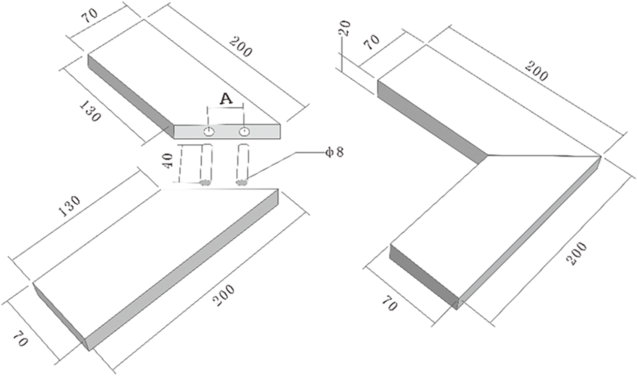
Figure 1: Assembly scheme diagram of dowel center spacing specimen (unit: mm)
Two structural parts were joined with dowels to test the influence of dowel center spacing on the bending and tensile strength of chamfered joints. Subsequently, the specimens were tested after two weeks of standing time. Tests were conducted using a Reger microcomputer-controlled electronic universal testing machine (Shenzhen Reger Instrument Co., Ltd., Shenzhen, China), displacement-loading curves were obtained as shown in the Fig. 2. Five groups were selected for the bending strength test using an electronic universal testing machine, and another five groups were selected for tensile strength testing using an electronic universal testing machine. The test setup is shown in Fig. 3.
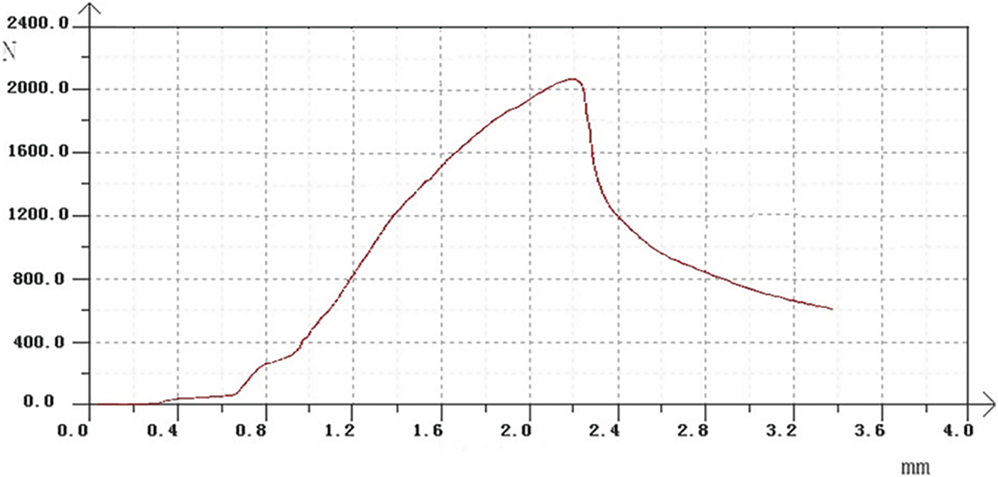
Figure 2: Typical displacement-loading curve
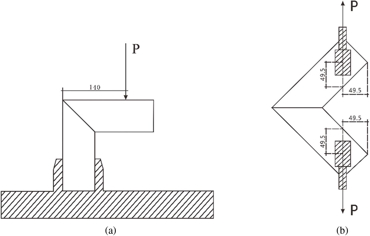
Figure 3: Setup of bending strength loading (a) and tensile strength loading (b) in chamfered-joint tests (unit: mm)
The general configuration of the specimens and the schematic diagram for chamfered joints in the bending strength tests are shown in Fig. 3a, and those for tensile strength tests are shown in Fig. 3b. Each specimen consisted of two structural members made of C. funebris wood and two dowels made of E. robusta wood.
3.1 Influence of Dowel Center Spacing on Bending Strength of Specimen
Failure mode analysis was performed, and the failure characteristics of the bending strength tests are shown in Fig. 4. Five treatment levels of dowel center spacing in the test were designed, and all level tests were repeated six times.
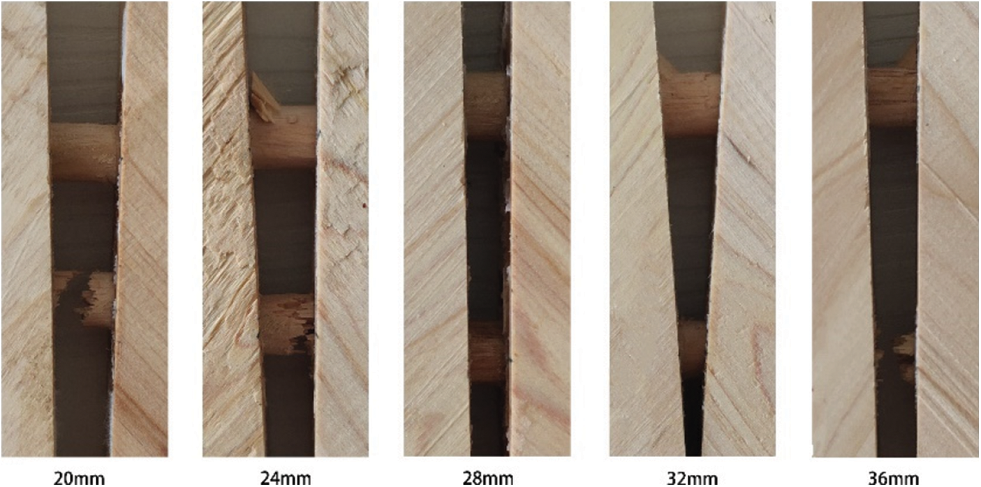
Figure 4: Failure modes of the specimens in bending strength tests of chamfered joints at different dowel center spacing
The top rows of the dowels were all near the outer-right angle of the chamfered joints, which were uniformly called outer dowels. In addition, the bottom row of the dowels were all near the inner right angle of the chamfered joints, which were uniformly called inner dowels.
Overall, the broken dowels were mainly concentrated on the side of the inner dowels, whereas the outer dowels were not broken or obviously torn, which was primarily due to different stresses on the inner and outer dowels when the bending strength was loaded.
The outer dowels are first affected by the external force exerted by the horizontal parts. The external force consists of the bending force that causes the outer dowels to bend and the pull-out force that causes the outer dowels to displace. Once the pull-out force of the outer dowels exceeded the bending force, the displacement degree of the outer dowels was greater than that of the inner dowels; however, the damage degree significantly exceeded that of the inner dowels.
When the displacement of the outer dowels reaches a certain point, the force is transmitted to the inner dowels, and a bending force is generated in the inner dowels. At this time, the pull-out force was relatively small and was mainly reflected in the bending deformation. When the bending force is greater than the strength of the inner dowels, the inner dowels bend or fracture.
The compressive stress on the inner wall of the mortise decreased with an increase in dowel center spacing, resulting in a decrease in the failure threshold of the specimens, which leads to a decrease in the bending strength with an increase in dowel center spacing.
The original data of the bending strength of the 30 specimens at five different dowel center spacing levels are shown in Table 1. As shown in Fig. 5, there is a positive linear correlation between dowel center spacing and bending strength for chamfered joints, which is dissimilar to those of other observations and studies on the influence of dowel center spacing on bending strength in two medium-density fiberboard structural members and two Japanese white birch dowels L-shaped joints [9,27], in which the structure is that two dowels side by side joined two structural members; however, the joint in this study was joined by the upper and lower dowels.
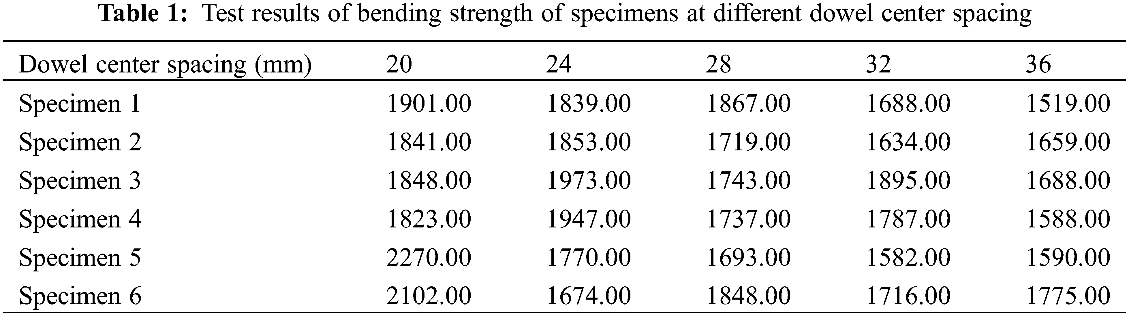
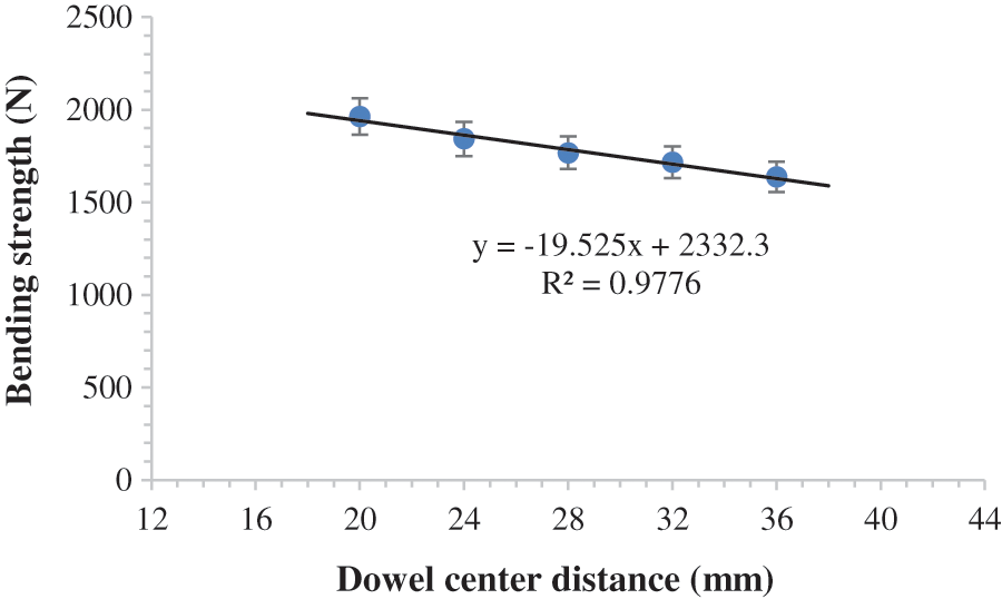
Figure 5: Linear fitting diagram for bending strength of dowel center spacing specimens
When the dowel center spacing was 20 mm, the values of bending strength reached a peak of 1964.17 N, which is also shown in Tables 1 and 2. As shown in Fig. 5, the regression equation was derived as follows: P = −19.525A + 2332.3, with 97.76% accuracy.
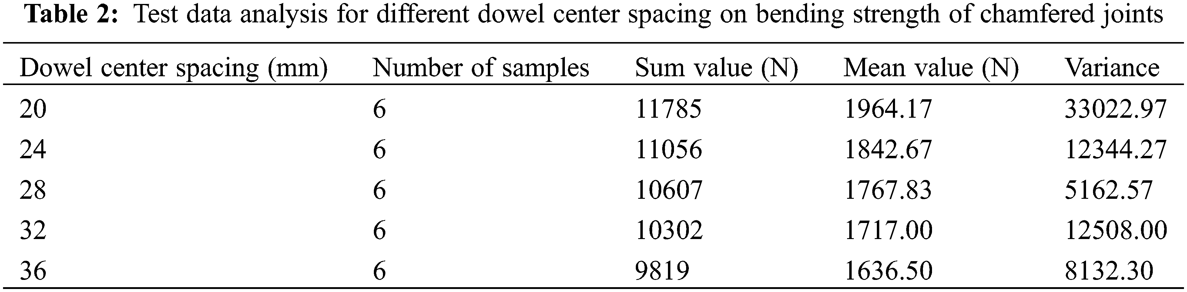
The preliminary analysis and calculation of the bending strength data of the specimens at different dowel center spacings are shown in Table 2. It can be observed from the average value that the bending strength decreases with increasing dowel center spacing. Further calculation and analysis show that the decrease in the value of each adjacent test level is approximately 120 N, and the extreme difference in the bending strength of the five test levels is 327.67 N.
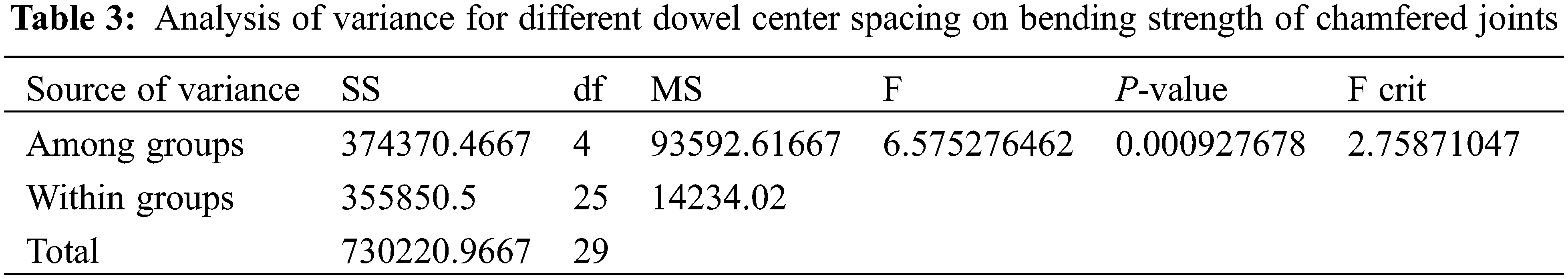
Table 3 shows ANOVA table of bending strength of specimens a different dowel center spacing, with a confidence level of 95%. P = 0.000927678, that is, P < 0.01, indicating that the bending strength of chamfered-jointed members is significantly affected by the dowel center spacing.
The mean value of the bending strength of chamfered joints ranged from 1600 to 2000 N at five experimental levels. It can be seen that the bending strength of chamfered joints decreases with an increase in dowel center spacing, indicating that dowel center spacing is negatively correlated with the bending strength of chamfered joints. It is suggested that the dowel center spacing between two dowels can be reduced properly in the actual machining process; thus, the bending strength of the chamfered joints can be higher.
3.2 Influence of Dowel Center Spacing on Tensile Strength of Specimen
Typical failure characteristics in the tensile strength of the dowel center spacing tests were obtained, as shown in Fig. 6. Thirty pairs of dowels in the dowel center-spacing specimen were tested at five experimental levels.
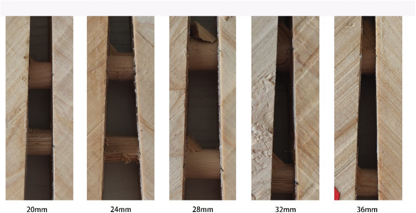
Figure 6: Failure modes of the specimens in tensile strength tests of chamfered joints at different dowel center spacing
Overall, the damage to the dowel center-spacing specimen was mainly concentrated on the two dowels, and the degree of damage of the outer dowels was slightly greater than that of the inner dowel. The main reason for this is that tensile loading has different effects on inner and outer dowels. First, displacement occurred on the inner dowel when tensile loads were applied. No bending strength is involved in this process, and the inner dowel does not bend. When the tensile strength is greater than the bonding force between the inner dowel and the mortise inner wall, the adhesive layer is damaged, accompanied by the tearing of wood fibers, and the connection between the inner dowel and C. funebris wood-chamfered joints fails. After the connection fails, the force begins to be transferred to the outer dowel. Because the inner dowel has been displaced for a distance, although the outer dowel has no displacement or the displacement degree is less than that of the inner dowel, the inner dowel will be subjected to bending force, and the bending axis is located at the right angle outside the miter plane; the outer dowel at this time is also affected by the pull-out force. When the dowel center spacing increases, the displacement gap between the inner and outer dowels increases, and the difference in the damage degree of the inner and outer dowels is greater. However, owing to the continuous increase in dowel center spacing, the mechanical properties around the location of the outer dowel will be weakened; thus, the damage degree of the outer dowel will be reduced, and it is obvious that when the dowel center spacing is 32–36 mm, the damage to the outer dowel is alleviated. When the dowel center spacing was between 20 mm and 32 mm, the damage degree of the chamfered joint test specimen gradually increased, whereas when the dowel center spacing was between 32 mm and 36 mm, the damage degree of the chamfered joint test specimen showed a decreasing tendency.
The original data of the tensile strength of 30 pairs of specimens with five different dowel center spacing levels are shown in Table 4. As shown in Fig. 7, there is a parabolic relationship between the dowel center spacing and the tensile strength of chamfered joints. It can be seen that when the dowel center spacing is 20 mm to 32 mm, the tensile strength of the chamfered joints increases continuously and peaked in 713.83 N at 32 mm. The tensile strength of the chamfered joints decreased when the dowel spacing was between 32 mm and 36 mm, as shown in Table 5 and Fig. 7. As shown in Fig. 7, the quadratic equation was derived as follows: P = −2.4732A2 + 145.75A-1445, with 95.75% accuracy.
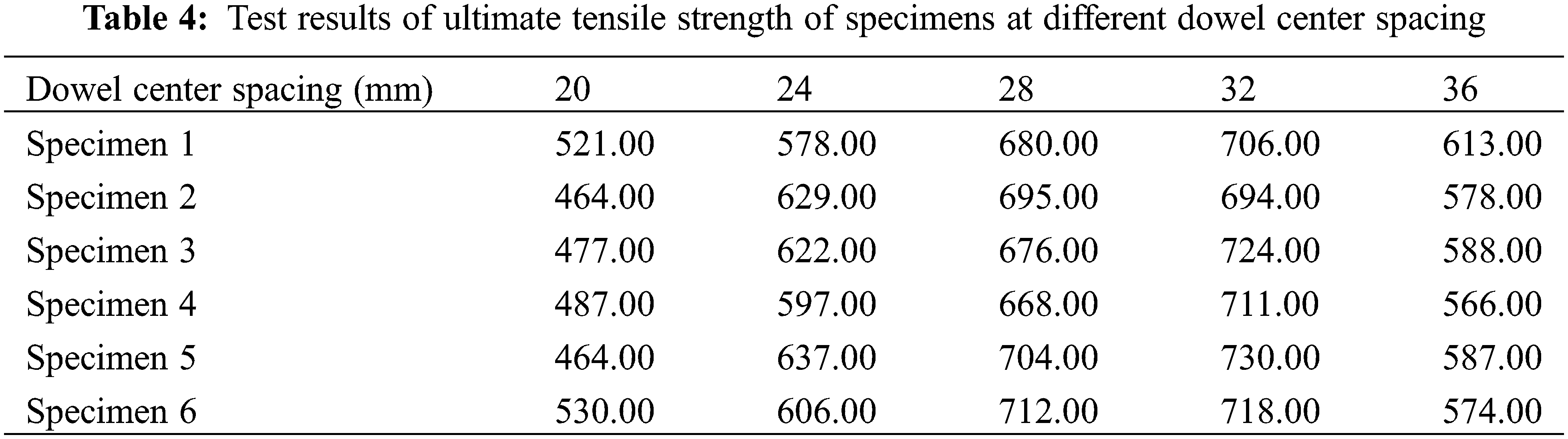
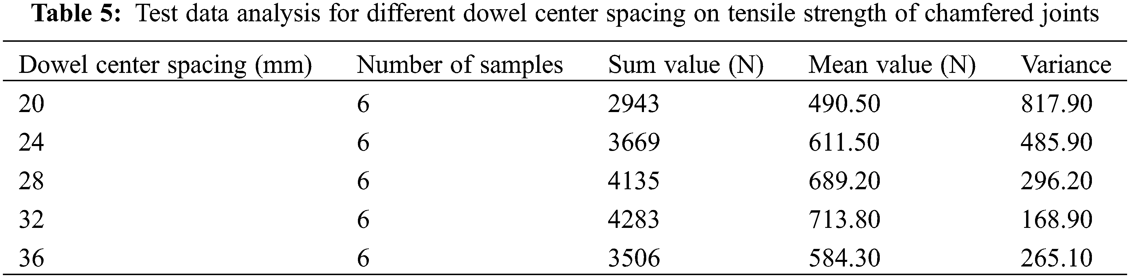
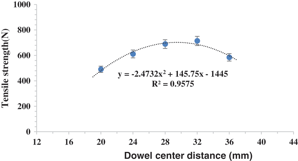
Figure 7: Linear fitting diagram for tensile strength of dowel center spacing specimens
The preliminary analysis and calculation of the tensile strength data of the specimens at different dowel center spacings are shown in Table 4. It can be seen from the average value that the tensile strength first increases and then decreases with increasing dowel center spacing, as shown in Fig. 7 and Table 5. Further calculation and analysis show that the extreme difference in the tensile strength of the five test levels is 223.33 N.
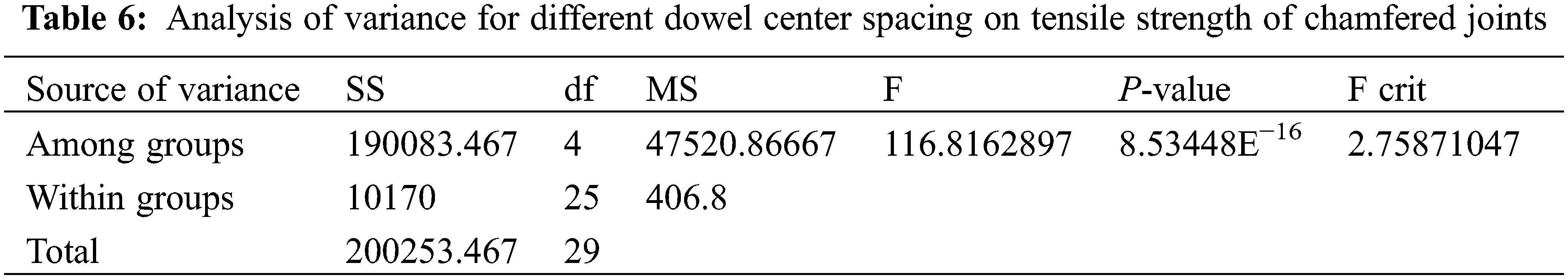
Table 6 shows ANOVA table of tensile strength of specimens with different dowel center spacing, with a confidence level of 95%. P = 8.53448E−16, that is, P < 0.01, indicating that the tensile strength of chamfered-jointed members is significantly affected by the dowel center spacing.
With an increase in dowel center spacing, the tensile strength of the chamfered joints changes in a parabola, first increasing and then decreasing. Specifically, when the dowel center spacing was from 20 mm to 32 mm, the tensile strength of the chamfered joints increased continuously. When the dowel center spacing was from 32 to 36 mm, the tensile strength of the chamfered joints decreased. When the dowel center spacing was 32 mm, the tensile strength of the chamfered joints reached a maximum value of 713.83 N. In the actual machining process, the dowel center spacing between two dowels is designed to be between 28 and 32 mm, making the C. funebris wood chamfered joints obtain the best tensile strength.
The bending strength and tensile strength regression equations were derived with dowel center spacing for C. funebris wood chamfered joints as follows: P1 = −19.525A + 2332.3 and P2 = −2.4732A2 + 145.75A-1445, with 97.76% and 95.75% accuracy, respectively.
The dowel center spacing had a significant effect on the bending and tensile strength of C. funebris wood chamfered joints (p < 0.01). Combined with the failure mode and test data analyses, the optimal dowel center spacing parameters for C. funebris wood chamfered joints in bending loading, and tensile loading were 20 mm and 32 mm, respectively.
In the production of C. funebris wood products, the bending strength of the C. funebris wood members joined with chamfered joints was significantly improved by decreasing the dowel center spacing within the allowable range of the specimen size. In addition, the optimum tensile strength of the C. funebris wood members joined with chamfered joints will be obtained by dowel center spacing values from 28 mm to 32 mm. To achieve the best match between theoretical calculation and practical application, the dowel center spacing in chamfered-joint components made of C. funebris wood should be 28 mm, considering the bending and tensile strength.
Acknowledgement: Any research results expressed in this paper are those of the writers and do not necessarily reflect the views of the foundations.
Funding Statement: The authors are grateful for the support of the Ministry of Education Humanities and Social Sciences Research Project of China (Grant No. 19YJC760009), the Key Research and Development Project of Sichuan Science and Technology Plan Projects (Grant No. 2020YFS0357) and the Project of Modern Design and Culture Research Centre (Grant No. MD18Z002).
Conflicts of Interest: The authors declare that they have no conflicts of interest to report regarding the present study.
References
1. Chen, C., Li, H., Dauletbek, A., Shen, F., Hui, D. et al. (2022). Properties and applications of bamboo fiber–A current-state-of-the art. Journal of Renewable Materials, 10(3), 605–624. DOI 10.32604/jrm.2022.018685. [Google Scholar] [CrossRef]
2. Dauletbek, A., Li, H., Lorenzo, R., Corbi, I., Corbi, O. et al. (2022). A review of basic mechanical behavior of laminated bamboo lumber. Journal of Renewable Materials, 10(2), 273–300. DOI 10.32604/jrm.2022.017805. [Google Scholar] [CrossRef]
3. Hu, W. G., Guan, H. Y. (2018). Numerical study on the bending strength of oval mortise and tenon joint. Journal of Northwest Forestry University, 33(5), 225–230 (in Chinese). DOI 10.3969/j.issn.1001-7461.2018.05.36. [Google Scholar] [CrossRef]
4. Zhang, X. Y. (2009). Study on mechanical properties of pine elliptical mortise joint (Master Thesis). Nanjing: Nanjing Forestry University (in Chinese). [Google Scholar]
5. Zhang, T., Hu, W. (2021). Numerical study on effects of tenon sizes on withdrawal load capacity of mortise and tenon joint. Wood Research, 66(2), 321–330. DOI 10.37763/wr.1336-4561/66.2.321330. [Google Scholar] [CrossRef]
6. Chen, M., Li, X. M., Lyu, J. H. (2018). Influence of dowel diameter and curing time on strength of double dowel joint. Wood Research, 63(4), 591–598. [Google Scholar]
7. Hu, W., Liu, N. (2020). Numerical and optimal study on bending moment capacity and stiffness of mortise-and-tenon joint for wood products. Forests, 11(5), 501. DOI 10.3390/f11050501. [Google Scholar] [CrossRef]
8. Hu, W., Liu, N., Guan, H. (2020). Experimental and numerical study on methods of testing withdrawal resistance of mortise-and-tenon joint for wood products. Forests, 11(3), 280. DOI 10.3390/f11030280. [Google Scholar] [CrossRef]
9. Chen, M., Lyu, J. H. (2018). Properties of double dowel joints constructed of medium density fiberboard. Maderas: Cienciay Tecnologia, 20(3), 369–380. DOI 10.4067/S0718-221X2018005003801. [Google Scholar] [CrossRef]
10. Chen, M., Li, S. G., Lyu, J. H. (2019). Effects of selected joint parameters on tensile strength of steel bolt-nut connections in Cupressus funebris wood. BioResources, 14(3), 5188–5211. DOI 10.15376/biores.14.3.5188-5211. [Google Scholar] [CrossRef]
11. Chen, M., Li, S. G., Lyu, J. H. (2019). Physical and mechanical properties of Cupressus funebris Endl. Wood. IOP Conference Series: Materials Science and Engineering, 493, 012105. DOI 10.1088/1757-899X/493/1/012105. [Google Scholar] [CrossRef]
12. Hill, M. D., Eckelman, C. A. (1973). Flexibility and bending strength of mortise and tenor joints. Furniture Design and Manufacturing, 45(1), 54–61. [Google Scholar]
13. Eckelman, C. A. (1979). Withdrawal strength of dowel joints: Effect of shear strength. Forest Products Journal, 29(1), 48–52. [Google Scholar]
14. Eckelman, C. A., Resheidat, M. (1984). Deflection analysis of shelves and case top and bottoms. Forest Products Journal, 34(6), 55–60. [Google Scholar]
15. Tankut, A. N., Tankut, N. (2005). The effects of joint forms(shape) and dimensions on the strengths of mortise and tenon joints. Turkish Journal of Agriculture & Forestry, 29(6), 493–498. [Google Scholar]
16. Dourado, N., Silva, F., Moura, M. D. (2018). Fracture behavior of wood-steel dowel joints under quasi-static loading. Construction and Building Materials, 176, 14–23. DOI 10.1016/j.conbuildmat.2018.04.230. [Google Scholar] [CrossRef]
17. Wang, X., Xu, Q., Wang, X., Guo, J., Cao, W. et al. (2020). Strength degradation of wood members based on the correlation of natural and accelerated decay experiments. Journal of Renewable Materials, 8(5), 565–577. DOI 10.32604/jrm.2020.09020. [Google Scholar] [CrossRef]
18. Wu, G., Zhong, Y., Gong, Y., Ren, H. (2019). Application of modern wood product glulam in timber frame with tenon-mortise joints and its structural behavior. Journal of Renewable Materials, 7(5), 451–461. DOI 10.32604/jrm.2019.06229. [Google Scholar] [CrossRef]
19. Li, H., Qiu, H., Wang, W. (2021). Experimental study on the mechanical performance of mortise-tenon joints reinforced with replaceable flat-steel jackets. Journal of Renewable Materials, 9(6), 1111–1125. DOI 10.32604/jrm.2021.014722. [Google Scholar] [CrossRef]
20. Zhu, X., Xue, Y., Zhang, X., Qi, P., Shen, J. et al. (2022). Study of the single shear performance of a joint with a new beech and self-tapping screw composite dowel. Journal of Renewable Materials, 10(2), 401–413. DOI 10.32604/jrm.2022.016464. [Google Scholar] [CrossRef]
21. Smardzewski, J. (2002). Strength of profile-adhesive joints. Wood Science and Technology, 36(2), 173–183. DOI 10.1007/s00226-001-0131-3. [Google Scholar] [CrossRef]
22. Zhong, S. L., Guan, H. Y. (2007). Relationship between optimal value of interference fit and wood density in oval-tenon joint. China Forestry Science and Technology, 21(2), 45–55 (in Chinese). DOI 10.3969/j.issn.1000-8101.2007.02.018. [Google Scholar] [CrossRef]
23. Wang, W. K. (2010). Study on the engagement parameters of pine elliptical tenon (Master Thesis). Nanjing: Nanjing Forestry University (in Chinese). [Google Scholar]
24. Eckelman, C. A., Suddarth, S. K. (1969). Analysis and design of furniture frames analysis. Wood Science and Technology, 3(3), 239–255. DOI 10.1007/BF00367215. [Google Scholar] [CrossRef]
25. Eckelman, C. A., Lin, F. C., Zhang, J. (2002). A technique for structural modeling of front rails for sofas. Holz als Roh- und Werkstoff, 60(1), 60–65. DOI 10.1007/s001070100244. [Google Scholar] [CrossRef]
26. Daudeville, L., Davenne, L., Yasumura, M. (1999). Prediction of load carrying capacity of bolted timber joint. Wood Science and Technology, 33(1), 15–29. DOI 10.1007/s002260050095. [Google Scholar] [CrossRef]
27. Dong, H. G., Shao, Z. P. (2007). Strength analysis of dowels in solid wood furniture. Wood Industry, 21(2), 38–40 (in Chinese). DOI 10.19455/j.mcgy.2007.02.013. [Google Scholar] [CrossRef]