| Journal of Renewable Materials |
DOI: 10.32604/jrm.2022.016464
ARTICLE
Study of the Single Shear Performance of a Joint with a New Beech and Self-Tapping Screw Composite Dowel
1College of Materials Science and Engineering, Nanjing Forestry University, Nanjing, 210037, China
2College of Civil Engineering, Yangzhou Polytechnic Institute, Yangzhou, 225127, China
3College of Architectural Science and Engineering, Yangzhou University, Yangzhou, 225127, China
*Corresponding Author: Changtong Mei. Email: mei@njfu.edu.cn
Received: 07 March 2021; Accepted: 30 April 2021
Abstract: A new beech and self-tapping screw composite dowel is proposed and studied, its performance being compared with that of beech dowels and self-tapping screws alone. The single shear performance of components connected by composite dowels was tested. Results show that the dowels are a good choice for components requiring high stiffness. Screws remain a good choice for components requiring excellent seismic performance. Combination group presents similar maximum load stiffness to those of composite dowels, but other ductility parameters are superior for composite dowels. The best connection mode was provided by two composite dowels. Based on connecting two points, structural elements with two composite dowels showed much better load bearing ability than when joined by two beech dowels or by two self-tapping screws separately. The structural element with two composite dowels not only presented better initial stiffness, but also exhibited a better ductility coefficient and less energy consumption. So, the composite dowels can be used for beam column connection, dowel laminated timber, and restoration or enhancement of ancient buildings.
Keywords: Composite dowel; beech dowel; self-tapping screw; single shear performance
With the development of wood-based engineering materials, especially laminated timber and cross-laminated timber (CLT), self-tapping screws (STSs) have been studied [1]. At the same time, traditional wood dowels are continuously used as a green and low-carbon alternative for connecting CLT [2–4]. A new wood dowel friction welding technology has also been attempted [5–8].
Teng found for the basic connection properties of STSs that as the angle decreased their withdrawal strength at first decreased and then increased. When pulling out the STSs driven in an end face, the damage was obvious brittle fracture [9]. A generic model approach was proposed by Brandner et al. [10,11] to calculate the withdrawal strength of axially-loaded STSs inserted in structural timber or glued to laminated timber products made of either coniferous or deciduous timber.
Several researchers have studied the performance of STS connection in glulam. For the difference between STS and nail connections, Sun found that a hex-head STS joint had stiffer and stronger lateral resistance performance, but lower deforming ability than a wire nail joint [12]. On the influence of thread, diameter and angle, the maximum load sustainable by screws with both double-threaded sections and fully threaded shanks were higher than those of single-threaded screws [13]. The screws with a diameter of 6 mm must be assigned to the lowest low-cycle ductility class [14]. All screws with diameter greater than or equal to 8 mm have the potential to be assigned to the highest low-cycle ductility class [14]. When Tomasi’s model was applied to the theoretical calculation of slip modulus of steel-wood joints with inclined screw connections, the agreement between theory and experiment for 45° to 90° angles was very good [15]. STSs were designed for use with steel plates and for glulam moment-resisting joints composed of inclined STSs with steel side plates. Agreements between predicted nonlinear behaviors and observed ones were good on the whole [16]. STSs have also been used in joining steel to timber, and for mass timber panel-concrete composite. Longer STSs can be used in a steel-to-timber composite joint with inclined screws to increase the embedded depth in the timber and thereby to obtain a higher shear capacity without causing a drop in shear stiffness. For joints with inclined screws, the use of tapper washers has been proposed [17]. STSs have also been used to connect mass timber panel-concrete composite to an insulation layer. The connections with screws at an insertion angle of 30° had a larger stiffness and strength than connections with screws inserted at a 45° angle [18–20]. Finite element analysis was used to analyze the mechanical characterization of STS connection. Based on experimental data and published analytical models, an extended parametric investigation has been presented, and a correlation formula proposed for the analysis of maximum resistance and stiffness variations [21,22].
The parameters for application of STSs in CLT have been studied in several papers. Sullivan determined strength and stiffness of shear connections with 8-mm and 10-mm diameter STSs by monotonic and cyclic tests [23]. Brown found that a ratio of one 90° STS for every two inclined STSs achieved significant increase in ductility and displacement capacity of approximately three times that of specimens with only inclined STSs [24]. With an increase of angle between the direction of STS insertion and the direction of wood texture, the phenomenon of wood surface tearing was more obvious. The stiffness and strength of specimens increased with an increase of angle [25]. Dong concluded that increasing length and diameter of STSs could significantly improve CLT shear strength. CLT shear strength with an STS at a 45° inclination angle was 28.3% higher than that when the CLT had a 30° STS inclination angle. A connection assembly with double fastener inclination showed a 50.7% greater shear strength than that of half-lapped joints [26]. On the other hand, Lin, by comparing STS to mortise-tenon connections, found that STS connections failed before the damage to the CLT material appeared, and the damage also occurred on the wood around connections, while mortise-tenon connections failed only after the damage to CLT appeared [27]. The group effect in STS shear connections between CLT panels has also been investigated. The group effect for the joint capacity can be expressed as 0.9n (where n is the number of the connection points) for all joints under static loading. In case of cyclic loading, a more pronounced group effect was observed that can be expressed as n0.9 [28]. Furthermore, by using finite element analysis, different types and widths of gaps, initial slip and delayed stiffening, as well as softening after exceeding the maximum load, can be considered. In addition, STSs have been used to connect wooden parallel chord trusses. Fatal pull-out of STSs occurred accompanying failures related to bending of bottom chords [29].
In the reinforcement field, STSs have been widely used in the crack of glulam and mortise-tenon joints. STS reinforcement improved the capacity of the beam in some cases up to 50% relative to unreinforced beams [30]. Another study showed that STS reinforced glulam connections manifested considerably more moment-carrying capacity than the respective unreinforced connections [31]. STS reinforcement leads to a more ductile, safer failure. It may not be worth using screws with partial threads for increased strength but it is worth using them to restore the ductility after cracks develop, to ensure a less brittle failure [32,33]. Thread lengths and screw-to-dowel distances have also been investigated. A screw with 33% thread on the point end can be as effective as a screw with 100% thread to control crack propagation under the same geometrical parameters of the connections [34]. Zuo et al. studied a new type of STS anchor depth, with screwing in different perspectives and screw spacing of glulam beams to study the effect on flexural performance. The recommended strengthening modes were: a 45° rotating beam bottom pin, a vertical anchor depth of 2/3 times the thickness of the high beam, and a screw spacing equal to the thickness of the high beam [35]. The compressive behavior increased substantially for the glulam specimens with STS reinforcement. The length, number and arrangement of the STSs had a great influence on the failure modes and the load-carrying capacities [36].
Working in the field of mortise-tenon joints for reinforcement, Li showed that the 5th percentile value of the capacity of beams with half-lap joints and with round dovetail joints reinforced by STSs could reach, respectively, 75.8%–76.7% and 75.9%–77.5% those of intact beams [37]. The maximum moment and failure rotation of plain round rod reinforcing connection were increased by 29% and 6%, respectively, relative to those with non-reinforced connections. In addition, those STS reinforcing connections increased by 86% and 145%, respectively [38]. Song studied the lateral performance of traditional heavy timber frames with mortise-tenon joints retrofitted using STS. The retrofitted frames exhibited smaller stiffness, larger deformability, higher damping ratio, and similar strength degradation from primary cycles to trailing cycles [39]. In the research of Sun, it is concluded that steel plates and STSs are suitable for the strengthening of mortise-tenon joints, the strength or rigidity of which is obviously inadequate [40].
As revealed in the studies outlined above, STS has been widely used for wooden structure. But two problems can arise in such applications. The first is the extrusion deformation caused by the STS pressed to the wood substrate. This phenomenon can reduce the stiffness of the joint. The second potential problem is that STSs and wood substrates have different drying shrinkage coefficients, which could lead to the appearance of cracks and gaps in the future. Wooden joints connected by wood dowels could avoid these two problems, but have a problem of their own, potential brittle failure.
In this study, a new beech and STS composite dowel is proposed. This composite dowel combines features of STS and a wood dowel. In Zhu’s study, a wood dowel could be broken by twisting [41,42]. On the other hand, Liu found that the twisting would be avoided when compressed wood was used, and the pullout resistance of compressed wooden dowel rotary friction welding could be increased [43]. Damage by twisting could be avoided by using beech dowels instead of birch dowels, and also by using the new composite dowel structural form proposed in this paper.
In the discussion below, we consider three connection styles. One style is two holes connected by just two STSs or wood dowels. The second connection style has four holes connected by both two STSs and wood dowels. The third style has two holes connected by composite dowels. The second and third styles are used to analyze the synergistic effects relative to the first style.
In this paper, we study the single shear performance of components connected by composite dowels.
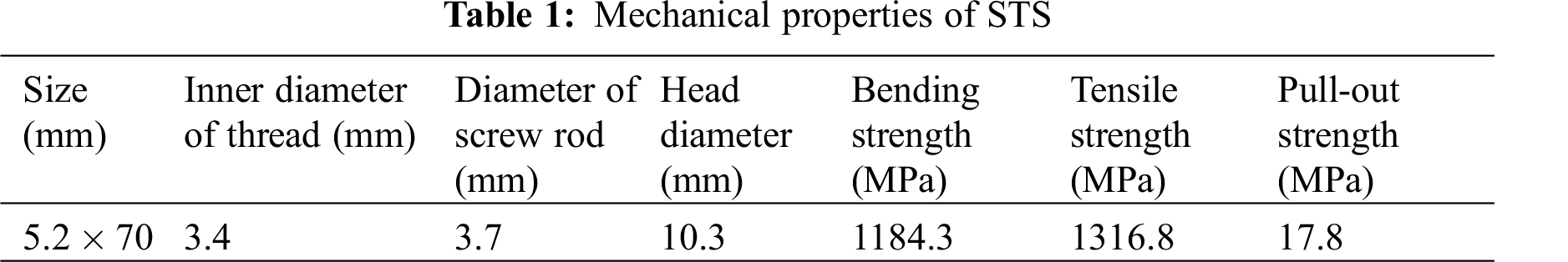
Wood dowels, 12 mm in diameter and 100 mm in length, were fabricated from beech wood (Zelkova schneideriana; Crownhomes, China). The dried density of the beech dowel at 2% moisture content was 703 kg/m3. The tensile force of these dowels was 6.31 kN. Their bending strength and elastic modulus were 93.68 MPa and 9862 MPa, respectively. STSs (Moregood, Shanghai, China), 5.2 mm in diameter and 70 mm in length, were galvanized. The STS mechanical properties are shown in Tab. 1. Spruce-Pine-Fir (SPF; material grade: II; Crownhomes, China) slats with width W = 89 mm, thickness T = 38 mm, and length L = 300–400 mm were used as substrates. The air-dried density of the larch at 9.7% MC was 495 kg/m3.
Wood dowels were welded into the pre-drilled holes in the substrates to create bonded joints at a high-speed rotation of 1500 rpm. The processing details of all the groups are listed in Tab. 2. Three specimens were prepared for Groups 1, 2, 3, and 4 (Figs. 1 and 2). For Group 3, the beech dowels of length 70 mm were pre-drilled with holes 3 mm in diameter and 70 mm in depth using a drilling machine. Then the STSs were screwed into the pre-drilled holes (Fig. 2). For Groups 1 and 4, 30 mm of beech dowels outside the substrates were cut after the welding process. And four holes were set in Group 4, two beech dowels and two STSs were combination arranged by row symmetry.
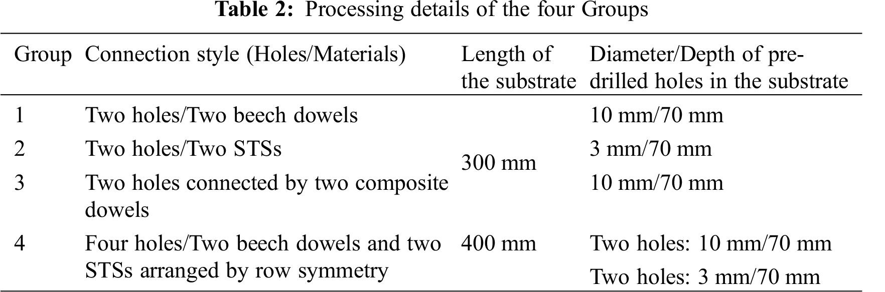
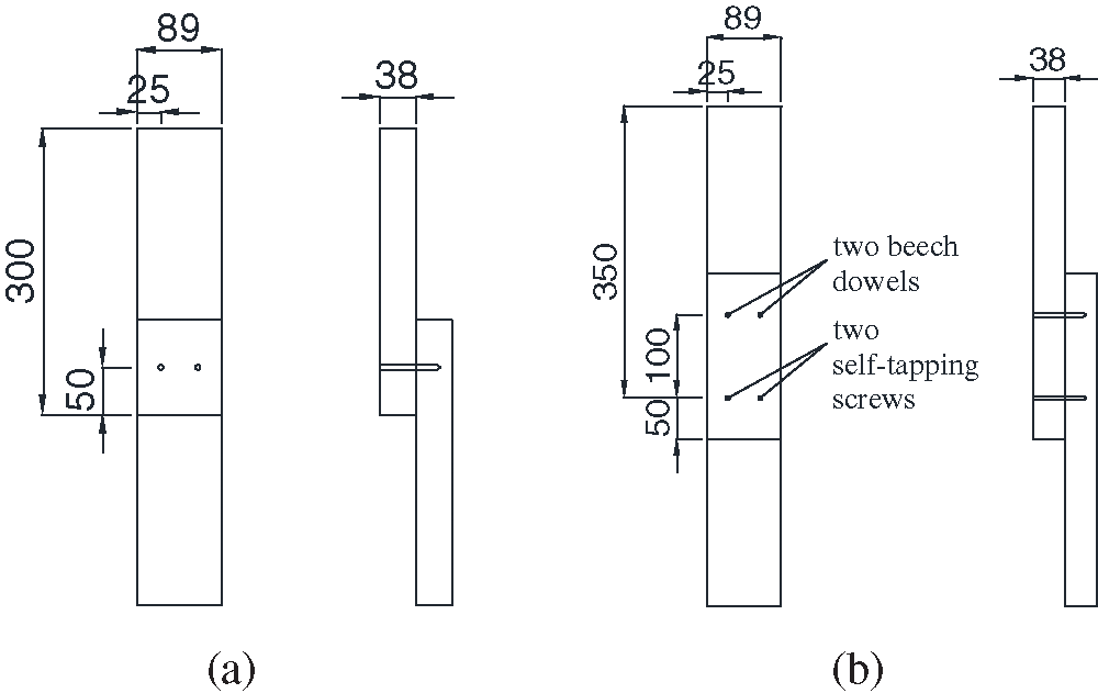
Figure 1: Single shear performance of samples from (a) Groups 1, 2, and 3, and (b) Group 4
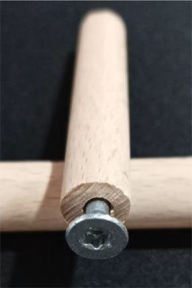
Figure 2: Composite dowel for Group 3
All the specimens were conditioned at 20°C and 60% relative humidity for 7 days before the tests were conducted. The single shear performances of the specimens were tested by traction, using a universal testing machine (Fig. 3, WDW-300E; Jinan Popwil, Jinan, China) at a speed of 5 mm/min.
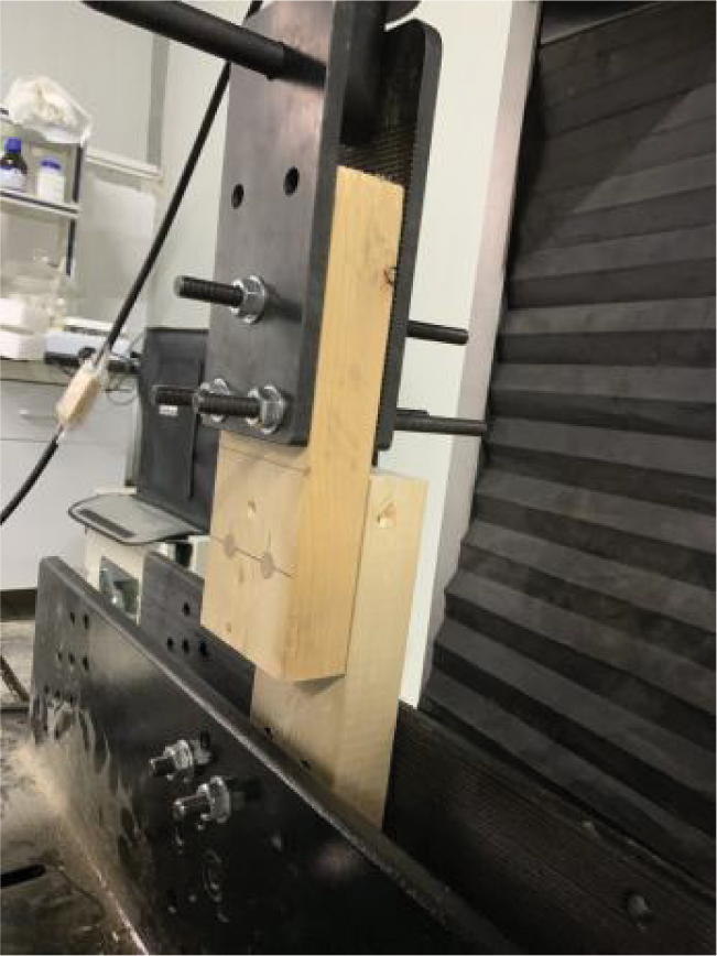
Figure 3: WDW-300E universal testing equipment
2.3 Analysis Method of Characteristic Value
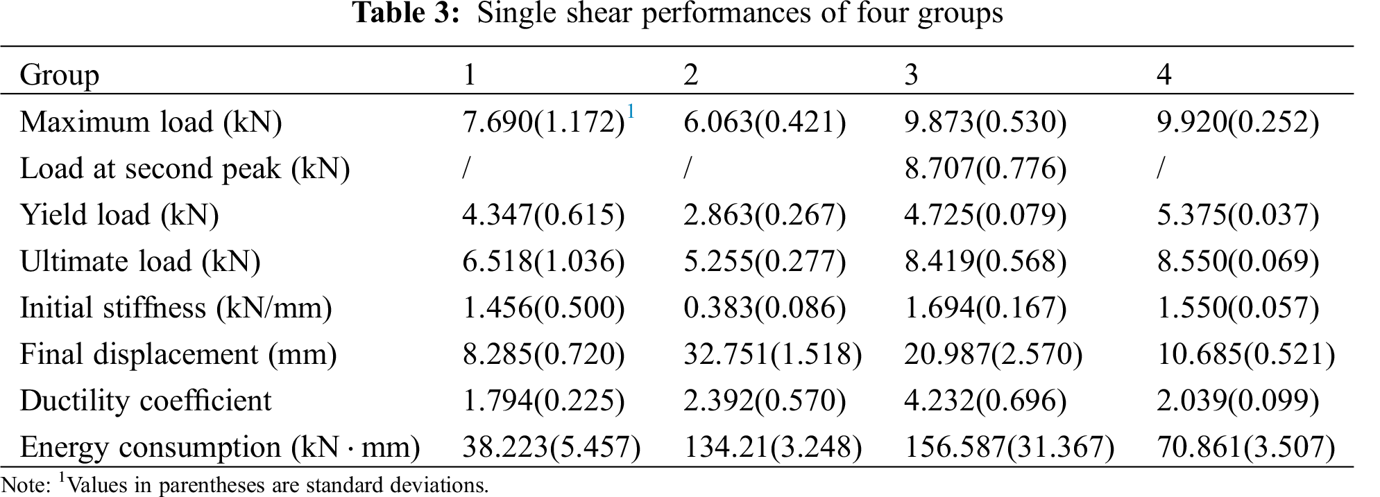
All the force-displacement curves were obtained from the single shear performance tests. Each force-displacement curve was eigenvalue analyzed by the characteristic value method (Fig. 4) [44]. The analysis allowed seven parameters to be calculated: maximum load (Pmax), ultimate load (Pu), yield load (Py), initial stiffness (Ki), ductility coefficient (μ), energy consumption (S), and final displacement (Du). These are shown for the four groups in Tab. 3. From Fig. 4, six lines can be found in the force-displacement diagram. The methodology is specified in the figure caption.
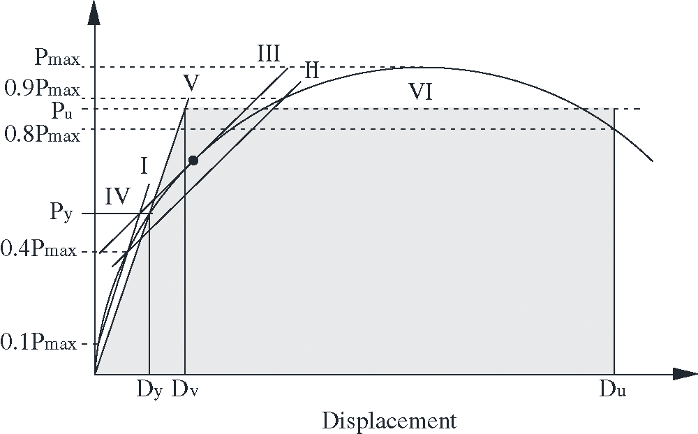
Figure 4: Force-displacement curve and methodology for finding characteristic values. I—Draw a line connecting points at 0.1 Pmax and 0.4 Pmax. II—Draw a line connecting points at 0.4 Pmax and 0.9 Pmax. III—Displace line II to be tangent to the force-displacement curve. IV—Draw a horizontal line through the intersection of lines I and III and extend this line to the force-displacement curve, where the ordinate value is Py and the abscissa value is Dy. V—Draw a line connecting the point (0, 0) and (Dy, Py). Its slope is the initial stiffness Ki. VI—Draw a line created the shadow area of Figure which was equal to the area created by the force-displacement curve, X-ray, and the line X = Du, the ratio of Du and Dv was ductility coefficient μ. The shadowed area (units force x distance) is the energy consumption of the entire single shear performance
3.1 The Difference between Groups 1, and 2
Typical force-displacement curves of Groups 1–4 are shown in Fig. 5. The maximum loads for Groups 1 and 2 appear near 7.5 mm and 25 mm displacement, respectively. Data in Tab. 3 show that the maximum load and ultimate load of Group 1 were, respectively, 26.83% and 24.03% higher than those of Group 2, while the yield load of Group 1 was 51.83% higher than that of Group 2. The curves in Fig. 5 help to explain this apparent anomaly. For Group 1, the inflection point is in the range of 4–5 kN, while it is at range of 2.5–3.5 kN for Group 2.
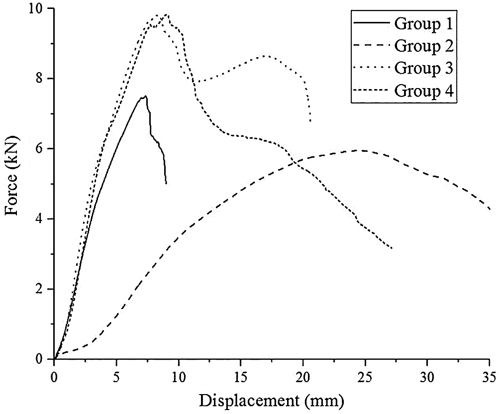
Figure 5: Force displacement curves of Groups 1, 2, 3, and 4
The initial stiffness of Group 1 was three times greater than that of Group 2 [45,46]. The dowels could be a selection for the high stiffness required by the component. According to the procedure during the test, the screws have been pulled out of the holes when the displacement exceeded 5 mm. At this time, the force was close to the yield load. The dowels had no obvious change when the force was close to the yield load. Based on the difference between the phenomena, the initial stiffness of Group 2 was much lower than that of Group 1. However, the final displacement of Group 2 was more than 3.95 times that of Group 1.
In the study of Hao et al. broken wood dowels were the main form of failure during the shear test [4,47]. Similar phenomena are shown in Fig. 6a for Group 1, where dowels show brittle fracture. The beech dowels broke suddenly when the shear force of the joint exceeded the carrying capacity of the beech dowels. But as shown in Fig. 6b for Group 2, the screws were bent during the final stage, because the STS showed good toughness. The failure modes of STSs were in accordance with Dong et al. [26,27]. On the other hand, the force-displacement curves for Group 1 descended sharply, while the curves of Group 2 descended slowly. Due to this difference, the ductility coefficient of Group 2 was higher than that of Group 1. Finally, the energy consumption of Group 2 was more than 3.5 times that of Group 1. Screws can be selected for components requiring excellent seismic performance.
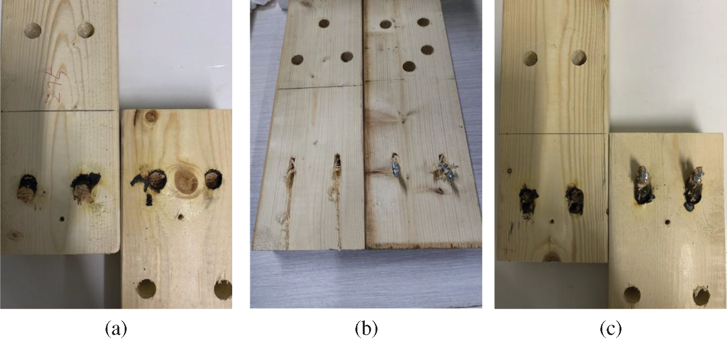
Figure 6: Failure modes of (a) Group 1, (b) Group 2, and (c) Group 3
3.2 The Relationships among Groups 1, 2, and 3
Fig. 5 shows that the force-displacement curves for Groups 1 and 2 each show only one peak, whereas there are two obvious peaks for Group 3. Fig. 6c, for Group 3, shows that the failure mode was a broken wood dowel and bent STS. The peak values for Groups 1 and 2 are in the range of displacement 7.5 mm and 25 mm, respectively. The peak values of Group 3 appear in the ranges of displacement around 7.5 mm and 17.5 mm. According to Tab. 3, the sum of the maximum load and the second peak value of Group 3 was 18.58 kN, while the sum of the maximum loads of Groups 1 and 2 was 13.753 kN. Both the maximum load and the second peak value of Group 3 were higher than the maximum load of either Groups 1 or 2.
The first peak values of Group 3 (the maximum loads) were 28.39% higher than those of Group 1. At this stage, the beech dowels bore most of the shear force, with the STSs in the beech dowels providing only a little. Before the first peak value, the curves of Groups 1 and 3 show the same tendency, with the initial stiffness of Group 3 being just 16.37% higher than that of Group 1. On the other hand, the curve of Group 3 shows a “V” after the first peak value, a result of the fact that the beech dowels were broken at this moment, while the STSs could not bear shear force alone due to the gap between STSs and beech dowels or substrates generated by the broken dowels. The second peak value of Group 3 was much higher than that of Group 2. The curves of Group 3 then declined sharply after the second peak values, while the curves of Group 2 declined slowly after the peak value. According to this phenomenon, the final displacement of Group 3 was much lower than that of Group 2 (see Tab. 3). But the ductility coefficient of Group 3 was equal to the sum of those coefficients of Groups 1 and 2. And the energy consumption of Group 3 was 16.67% and 309.67% higher than those of Groups 1 and 2, respectively.
Based on the discussion above, the properties of Group 3 were the best among Groups 1, 2, and 3. The better initial stiffness of Group 1 and better ductility and energy consumption of Group 2 could be found in Group 3. Obvious synergistic effect of wood dowel and STS could be found in Group 3. So, whether the component requires high stiffness or excellent seismic performance, the composite dowels should be an excellent choice.
3.3 The Differences among Groups 1, 2, and 4
As indicated in Fig. 5 and Tab. 3, the maximum load of combination Group 4 was higher than that of either Group 1 or Group 2 alone [28,48], but lower than the sum of the values for Groups 1 and 2. The same trend can be found in the yield load and ultimate load. As shown in Fig. 5, the first half of the curve of Group 4 is similar to the curve of Group 1, and the second half of the curve is similar to the curve of Group 2. When the load reaches the maximum load of Group 1, the trend of the curve of Group 4 keeps on increasing until it reaches the maximum load. Then the curve of Group 4 descends sharply to 6 kN at 15 mm, which was the maximum load point of Group 2. At this time, the decline slows. These curves show a downward trend similar to that of Group 2. The failure mode of Group 4 was observed during the test (Fig. 7). The two dowels were broken at the maximum load, and then the two STSs played an important role in the loading process. But as shown in the first half of the curve, the two STSs made little contribution to the loading process. So, the second half of the curve descends more sharply than that of Group 2. The initial stiffness of Group 4 was a little higher than that of Group 1 [48]. And the ductility of Group 4 was between that of Groups 1 and 2. But the final displacement and energy consumption of Group 4 were much lower than those of Group 2. This could be caused by the effect of the two dowels and two screws acting on the combination group independently. Based on the discussion above, the properties of Group 4 were better than those of Groups 1 and 2. But they were not as good as the sum of the corresponding properties of Groups 1 and 2. So, no obvious synergistic effect of wood dowel and STS could be found in Group 4.
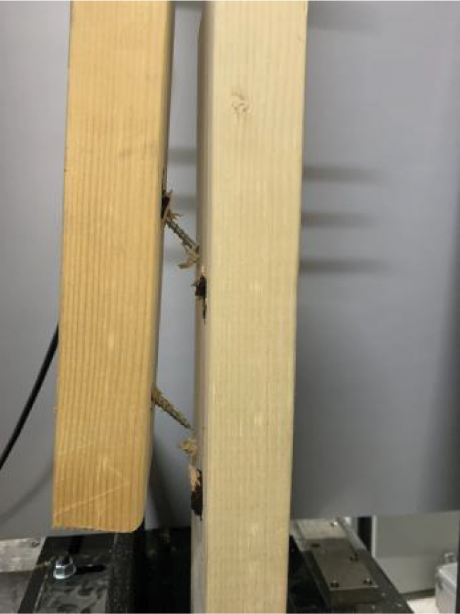
Figure 7: Failure mode of Group 4
3.4 The Difference between Groups 3 and 4
As shown in Tab. 3, the maximum load, yield load, ultimate load, and initial stiffness of Group 3 were similar to those of Group 4. But the final displacement, ductility coefficient, and energy consumption of Group 3 were twice as much as for Group 4. Fig. 5 shows that the curve of Group 3 is similar to that of Group 4 before the 10-mm displacement, after which a difference shows itself. For Group 4, the curve descends after 10 mm, while for Group 3, the curve increases again until it reaches a second peak. At the end stage, the displacement of Group 3 was around 20 mm and that of Group 4, 35 mm. So, unlike Group 4, Group 3 makes the two beech dowels and two STSs work together. Yet Group 3 bears a load better than does Group 4.
All of the groups were used to connect the components. Group 4 needed to connect four holes, while Group 3 needed to connect only two. Yet Group 3 showed better properties than did Group 4. So the composite dowels are recommended instead of beech dowels for connecting the components, or else STSs used alone, rather than the combination style mentioned above. For example, the composite dowels could be used in the field of beam column connection, dowel laminated timber, and restoration or enhancement of ancient buildings.
Dowels should be selected for component requiring high stiffness. Screws can be selected for components requiring excellent seismic performance. The connection mode using two composite dowels was found to be the best choice in this work. The components of two composite dowels showed much better load bearing than did two beech dowels or two STSs independently. Obvious synergistic effect of wood dowel and STS could be found in composite dowels. Whereas the combination group presents similar maximum load and stiffness to those presented by composite dowels, but the ductility parameters are far less than those of the composite dowels.
The components of two composite dowels not only presented better initial stiffness, but also exhibited a better ductility coefficient and energy consumption. So, composite dowels are good choices for use in beam column connection, dowel laminated timber, and restoration or enhancement of ancient buildings.
Acknowledgement: All authors contributed equally to this work. We thank TopEdit (https://www.topeditsci.com) for its linguistic assistance during the preparation of this manuscript.
Funding Statement: The authors are grateful for the support of the National Natural Science Foundation of China (Grant No. 31901252), the Natural Science Foundation of Jiangsu Province, China (Grant No. BK20180276), Jiangsu Planned Projects for Postdoctoral Research Funds (Grant No. 2020Z075), the Science and Technology Program of Jiangsu Housing and Construction Department (Grant Nos. 2018ZD118 and 2020ZD29), Qing Lan Project of Jiangsu, the Yangzhou Science and Technology Project (Grant No. SGH2020010040), and Yangzhou Polytechnic Institute Project (Grant No. 2019xjzk007).
Conflicts of Interest: The authors declare that they have no conflicts of interest to report regarding the present study.
1. Chen, H., Liu, Z. B., Li, S. Z., He, X. P. (2019). A summary of research on the connection performance of new self-tapping screws in wood structures. Shanxi Architecture, 45(1), 34–35. DOI 10.13719/j.cnki.cn14-1279/tu.2019.01.020. [Google Scholar] [CrossRef]
2. Hao, J. X., Xu, L., Wu, X. F., Li, X. J. (2020). Analysis and modeling of the dowel connection in wood T type joint for optimal performance. Composite Structures, 253, 1–11. DOI 10.1016/j.compstruct.2020.112754. [Google Scholar] [CrossRef]
3. Bui, T. A., Oudjene, M., Lardeur, P., Khelifa, M., Rogaume, Y. (2020). Towards experimental and numerical assessment of the vibrational serviceability. Engineering Structures, 216, 1–10. DOI 10.1016/j.engstruct.2020.110586. [Google Scholar] [CrossRef]
4. Li, Q., Song, H., Wang, Z. Q. (2020). Bending performance of timber composite beam fastened with bamboo/wood dowels. Journal of Northwest Forestry University, 35(2), 218–222. DOI 10.3969/j.issn.1001-7461.2020.02.33. [Google Scholar] [CrossRef]
5. Bocquet, J. F., Pizzi, A., Resch, L. (2007). Full-scale industrial wood floor assembly and structures by welded-through dowels. European Journal of Wood and Wood Products, 65(2), 149–155. DOI 10.1007/s00107-006-0170-4. [Google Scholar] [CrossRef]
6. Bocquet, J. F., Pizzi, A., Despres, A., Mansouri, H. R., Resch, L. et al. (2017). Wood joints and laminated wood beams assembled by mechanically-welded wood dowels. Journal of Adhesion Science and Technology, 21(3/4), 301–317. DOI 10.1163/156856107780684585. [Google Scholar] [CrossRef]
7. Girardon, S., Barthram, C., Resch, L., Bocquet, J. F., Triboulot, P. (2014). Determination of shearing stiffness parameters to design multi-layer spruce beams using welding-through wood dowels. European Journal of Wood and Wood Products, 72(6), 721–733. DOI 10.1007/s00107-014-0834-4. [Google Scholar] [CrossRef]
8. Satoshi, F., Keita, O., Masaki, N., Yamasaki, M., Sasaki, Y. (2017). Shear properties of metal-free wooden load-bearing walls using plywood jointed with a combination of adhesive tape and wood dowels. European Journal of Wood and Wood Products, 75(3), 429–437. DOI 10.1007/s00107-016-1084-4. [Google Scholar] [CrossRef]
9. Teng, Q. C., Wang, F. B., Que, Z. L., Zeng, N. (2019). Effects of angles on the screw and nail withdrawal strength in dimension lumber. Scientia Silvae Sinicae, 56(1), 154–161. DOI 10.11707/j.1001-7488.20200115. [Google Scholar]
10. Brandner, R. (2019). Properties of axially loaded self-tapping screws with focus on application in hardwood. Wood Materials Science and Engineering, 14(6), 1–15. DOI 10.1080/17480272.2019.1635204. [Google Scholar] [CrossRef]
11. Brandner, R., Ringhofer, A., Reichinger, T. (2019). Performance of axially-loaded self-tapping screws in hardwood properties and design. Engineering Structures, 188, 677–699. DOI 10.1016/j.engstruct.2019.03.018. [Google Scholar] [CrossRef]
12. Sun, Y. H., Jiang, Z. H., Zhang, X. B., Sun, Z. J., Liu, H. R. (2019). Behavior of glued laminated bamboo and bamboo-oriented strand board sheathing-to-framing connections. European Journal of Wood and Wood Products, 77, 1189–1199. DOI 10.1007/s00107-019-01454-3. [Google Scholar] [CrossRef]
13. Yeh, M. C., Lin, Y. L., Huang, G. P. (2014). Investigation of the structural performance of glulam beam connections using self-tapping screws. Journal of Wood Science, 60, 39–48. DOI 10.1007/s10086-013-1376-9. [Google Scholar] [CrossRef]
14. Izzi, M., Polastri, A. (2019). Low cycle ductile performance of screws used in timber structures. Construction and Building Materials, 217, 416–426. DOI 10.1016/j.conbuildmat.2019.05.087. [Google Scholar] [CrossRef]
15. Lu, X. R., Teng, Q. C., Li, Z. R., Zhang, X. L., Wang, X. M. et al. (2020). Study on shear property of spruce glulam and steel plate connected with inclined screw. Journal of Forestry Engineering, 5(3), 48–53. DOI 10.13360/j.issn.2096-1359.201906005. [Google Scholar]
16. Komatsu, K., Teng, Q. C., Li, Z. R., Zhang, X. L., Que, Z. L. (2019). Experimental and analytical investigation on the nonlinear behaviors of glulam moment-resisting joints composed of inclined self-tapping screws with steel side plates. Advances in Structural Engineering, 22(15), 3190–3206. DOI 10.1177/1369433219858722. [Google Scholar] [CrossRef]
17. Wang, C. L., Lyu, J. F., Zhao, J., Yang, H. F. (2020). Experimental investigation of the shear characteristics of steel-to-timber composite joints with inclined self-tapping screws. Engineering Structures, 215(15), 1–17. DOI 10.1016/j.engstruct.2020.110683. [Google Scholar]
18. Mirdad, M. A. H., Chui, Y. H. (2019). Load-slip performance of mass timber panel-concrete (MTPC) composite connection with self-tapping screws and insulation layer. Construction and Building Materials, 213, 696–708. DOI 10.1016/j.conbuildmat.2019.04.117. [Google Scholar] [CrossRef]
19. Mirdad, M. A. H., Chui, Y. H. (2020). Strength prediction of mass-timber panel concrete-composite connection with inclined screws and a gap. Journal of Structural Engineering, 146(8), 1–13. DOI 10.1016/j.engstruct.2020.110215. [Google Scholar]
20. Mirdad, M. A. H., Chui, Y. H. (2020). Stiffness prediction of mass timber panel-concrete (MTPC) composite connection with inclined screws and a gap. Engineering Structures, 207, 1–11. DOI 10.1016/j.engstruct.2020.110215. [Google Scholar] [CrossRef]
21. Bedon, C., Fragiacomo, M. (2019). Numerical analysis of timber-to-timber joints and composite beams with inclined self-tapping screws. Composite Structures, 207, 13–28. DOI 10.1016/j.compstruct.2018.09.008. [Google Scholar] [CrossRef]
22. Bedon, C., Sciomenta, M., Fragiacomo, M. (2020). Mechanical characterization of timber-to-timber composite (TTC) joints with self-tapping screws in a standard push-out setup. Applied Sciences, 10(18), 1–23. DOI 10.3390/app10186534. [Google Scholar] [CrossRef]
23. Sullivan, K., Miller, T. H., Gupta, R. (2018). Behavior of cross-laminated timber diaphragm connections with self-tapping screws. Composite Structures, 168, 505–524. DOI 10.1016/j.engstruct.2018.04.094. [Google Scholar] [CrossRef]
24. Brown, J. R., Li, M. H., Tannert, T., Moroder, D. (2020). Experimental study on orthogonal joints in cross-laminated timber with self-tapping screws installed with mixed angles. Engineering Structures, 228(1), 1–14. DOI 10.1016/j.engstruct.2020.111560. [Google Scholar]
25. Chang, C., Fang, Y. F., Liu, Y. F., Que, Z. L. (2019). Study on pull-out performance of tilted self-tapping screw in cross-laminated timber. Architecture Technology, 50(4), 416–418. DOI CNKI:SUN:JZJI.0.2019-04-009. [Google Scholar]
26. Dong, W. Q., Yao, Y., Song, H., Qi, Y. Y., Ren, H. Q. et al. (2018). Shear strength of cross-laminated timber connected with self-tapping screws. China Wood Industry, 32(5), 1–5. DOI 10.19455/j.mcgy.20180501. [Google Scholar]
27. Lin, Q. Y., Wen, C. S., Diao, Y., Yan, L. R., Gao, Y. (2019). Mechanical properties of CLT shear connections between self-tapping screws and mortise tenons. Journal of Beijing Forestry University, 41(11), 146–154. DOI 10.13332/j.1000-1522.20190209. [Google Scholar]
28. Hossain, A., Popovski, M., Tannert, T. (2019). Group effects for shear connections with self-tapping screws in CLT. Journal of Structural Engineering, 145(8), 1–9. DOI 10.1061/(ASCE)ST.1943-541X.0002357. [Google Scholar] [CrossRef]
29. Komatsu, K., Teng, Q. C., Li, Z. R., Zhang, X. L., Que, Z. L. (2018). Experimental and numerical analyses on nonlinear behaviour of wooden parallel chord trusses composed of self-tapping screws. Journal of Wood Science, 64(2), 776–793. DOI 10.1007/s10086-018-1774-0. [Google Scholar] [CrossRef]
30. Johan, J. (2005). Load carrying capacity of curved glulam beams reinforced with self-tapping screws. Holz als Roh-und Werkstoff, 63, 342–346. DOI 10.1007/s00107-005-0016-5. [Google Scholar] [CrossRef]
31. Petrycki, A., Salem, S. (2020). Structural integrity of bolted glulam frame connections reinforced with self-tapping screws in a column removal scenario. Journal of Structural Engineering, 146(10), 1–13. DOI 10.1061/(ASCE)ST.1943-541X.0002792. [Google Scholar] [CrossRef]
32. Zhang, C., Guo, H. B., Jung, K., Harris, R., Chang, W. S. (2019). Using self-tapping screw to reinforce dowel-type connection in a timber portal frame. Engineering Structures, 178, 656–664. DOI 10.1016/j.engstruct.2018.10.066. [Google Scholar] [CrossRef]
33. Zhang, C., Guo, H. B., Jung, K., Harris, R., Chang, W. S. (2019). Screw reinforcement on dowel-type moment-resisting connections with cracks. Construction and Building Materials, 215, 59–72. DOI 10.1016/j.conbuildmat.2019.04.160. [Google Scholar] [CrossRef]
34. Zhang, C., Harris, R., Chang, W. S. (2020). Strain distribution of dowel-type connections reinforced with self-tapping screws. Journal of Materials in Civil Engineering, 32(1), 1–13. DOI 10.1061/(ASCE)MT.1943-5533.0002883. [Google Scholar] [CrossRef]
35. Zuo, H. L., Liu, H. R., Lu, J. X. (2020). Effect of new self-tapping screw reinforcement measures on bending performance of glulam beams. Journal of Northeast Forestry University, 48(5), 112–116. DOI 10.13759/j.cnki.dlxb.2020.05.022. [Google Scholar]
36. Tang, L. Q., Xu, W., Yang, H. F., Tan, G. H., Chen, Y. (2021). Compressive strength tests perpendicular to the grain of glulam reinforced with self-tapping screws. Journal of Nanjing Technology University (Natural Science Edition), 43(1), 94–100. DOI 10.3969/j/issn.1671-7627.2021.01.014. [Google Scholar]
37. Li, H. M., Lam, F., Qiu, H. X. (2019). Comparison of glulam beam-to-beam connections with round dovetail and half-lap joints reinforced with self-tapping screws. Construction and Building Materials, 227, 1–11. DOI 10.1016/j.conbuildmat.2019.07.163. [Google Scholar] [CrossRef]
38. He, M. J., Liu, H. F. (2015). Comparison of glulam post-to-beam connections reinforced by two different dowel-type fasteners. Construction and Building Materials, 99, 99–108. DOI 10.1016/j.conbuildmat.2015.09.005. [Google Scholar] [CrossRef]
39. Song, X. B., Li, K., Crayssac, E., Wu, Y. J. (2018). Lateral performance of traditional heavy timber frames with mortise-tenon joints retrofitted using self-tapping screws. Journal of Structural Engineering, 144(10), 1–10. DOI 10.1061/(ASCE)ST.1943-541X.0002191. [Google Scholar] [CrossRef]
40. Sun, Z. Y., Cheng, X. W., Lu, W. D. (2018). Experimental study on seismic performance of damaged straight mortise-tenon joints of ancient timber buildings strengthened with steel plates and self-tapping screws. Structural Engineers, 34(5), 106–112. DOI 10.15935/j.cnki.jggcs.2018.05.015. [Google Scholar]
41. Zhu, X. D., Gao, Y., Yi, S., Ni, C., Zhang, J. et al. (2017). Mechanics and pyrolysis analyses of rotation welding with pretreated wood dowels. Journal of Wood Science, 63(3), 216–224. DOI 10.1007/s10086-017-1617-4. [Google Scholar] [CrossRef]
42. Zhu, X. D., Xue, Y. Y., Zhang, S. J., Zhang, J., Shen, J. et al. (2018). Mechanics and crystallinity/thermogravimetric investigation into the influence of the welding time and CuCl2 on wood dowel welding. BioResources, 13(1), 1329–1347. DOI 10.15376/biores.13.1.1329-1347. [Google Scholar] [CrossRef]
43. Liu, K. (2019). Study on pullout resistance of compressed wooden dowel rotary friction welding (Master Thesis). Dalian University of Technology, China. [Google Scholar]
44. Diao, Y., Jia, H. R., Meng, X. M., Gao, Y., Zhang, J. N. (2019). Comparison study on characteristic analysis methods of CLT wall-to-floor T connection under shear test. Journal of Beijing Forestry University, 41(8), 147–153. DOI 10.13332/j.1000-1522.20190161. [Google Scholar] [CrossRef]
45. Dong, W. B., Gao, Y., Yu, Z. M., Yuan, T. G. (2015). Experimental research on MIDPLY shear wall nail joints of light wood structures. Building Structure, 45(6), 54–57. DOI JournalArticle/5b3b898ac095d70f007be855. [Google Scholar]
46. Xiong, H. B., Pan, Z. F., Kang, J. H., Hua, M. X. (2011). Test study on behavior of stud-to-sheathing nail joints under monotonic load in light wood frame constructions. Structural Engineers, 6, 106–112. DOI 10.15935/j.cnki.jggcs.2011.06.025. [Google Scholar] [CrossRef]
47. Hao, J. X., Xu, L., Wu, X. F., Li, X. J. (2020). Analysis and modeling of the dowel connection in wood T type joint for optimal performance. Composite Structures, 253, 1–11. DOI 10.1016/j.compstruct.2020.112754. [Google Scholar] [CrossRef]
48. Liu, H. F., He, M. J. (2015). Effects of self-tapping screw on performance of glulam beam-to-column connections. Journal of Building Structures, 7, 148–156. DOI 10.14006/j.jzjgxb.2015.07.019. [Google Scholar]
 | This work is licensed under a Creative Commons Attribution 4.0 International License, which permits unrestricted use, distribution, and reproduction in any medium, provided the original work is properly cited. |