| Journal of Renewable Materials |
DOI: 10.32604/jrm.2022.020167
ARTICLE
Simulation Research on Performance of a Novel Heating and Cooling System with Thermoelectric Module
College of Mechanical and Electrical Engineering, Qingdao University, Qingdao, 266071, China
*Corresponding Author: Yihua Zheng. Email: yihua.zheng@qdu.edu.cn
Received: 08 November 2021; Accepted: 25 January 2022
Abstract: This work proposes a novel heating and cooling system, with incorporated thermoelectric module, that can achieve energy balance using a self-water supply heat exchange subsystem. The thermoelectric effect is used to achieve controlled and adjustable heating of the circulating water. Simulations were conducted to study the thermal performance of the system while it simultaneously produces hot and cold water, with different working conditions for the hot-and cold-side water outlets. The results show that the water temperature at the hot side outlet increases from 32°C to 75°C when the power increases from 4.5 to 50 W. Additionally, the use of thermoelectric modules to heat water and recover waste heat is 22% more efficient than ordinary electric water heating systems.
Keywords: Thermoelectric module; energy complementarity; waste heat recovery
Nomenclature
| DC | direct current |
| Sm | Seebeck coefficient of Thermoelectric module (VK−1) |
| Th0 | thermoelectric hot side temperature in supplier’s datasheet (°C) |
| Rm | electrical resistance of thermoelectric module (Ω) |
| V | voltage in volts (V) |
| Vmax | maximum voltage applied to the thermoelectric module (V) |
| I | current intensity in amperes (A) |
| Imax | maximum current intensity applied to the thermoelectric module (A) |
| Km | thermal conductance of thermoelectric generation module (WK−1) |
| Qc | power absorbed in cooling in watts (W) |
| Qh | power generated in heating in watts (W) |
| Th | hot side temperature of thermoelectric module (K) |
| Tc | cold side temperature of thermoelectric module (K) |
| ΔTmax | maximum temperature difference between faces (°C) |
| Qr | the heat absorbed by the hot water (W) |
| Qa | the heat absorbed by the cold water (W) |
| m | water mass |
| cp | water specific heat |
| ΔT | water temperature difference |
| We | electrical power consumed by the thermoelectric module (W) |
| Wh | hot water temperature (°C) |
| Wc | cold water temperature (°C) |
| Tw | water temperature (°C) |
A thermoelectric element is a solid-state system, composed of many alternating p-type and n-type semiconductor heat elements, that converts electrical energy into heat energy with a high heat flux [1]. The heat elements are connected in series with each other through metal and sandwiched between two electrically insulated and heat-conducting ceramic substrates. Thermoelectric systems follow the same laws of thermodynamics as mechanical heat pumps, steam compressors (such as those in traditional refrigerators), and other devices used to transfer energy [2]. Depending on the direction of the current, they can act as coolers, heaters, generators, or sensors. Thermoelectric devices have several advantages including their lack of moving parts or working fluids, compactness, low environmental impact, and long life [3]. As a results, they are used in a variety of applications such as aerospace [4], instrumentation [5,6], medical [7], industrial [8–10] and automotive [11,12].
Thermoelectric elements are widely used for both cooling and heating. Ahammed et al. [13] investigated the performance of a nanofluid-cooled multiport minichannel heat exchanger coupled with a thermoelectric cooler, designed for cooling an electronic device; results showed that cooling the thermoelectric module with nanofluid provided lower water cabin temperatures and higher COP values than cooling with pure water. Chein et al. [14] reported that a minimum water temperature could be obtained by increasing the electrical current input, decreasing the heat sink thermal resistance, or doing both simultaneously. Combining a thermoelectric module with a heat pipe and liquid circulation cooling, Çağlar [15] constructed a portable mini thermoelectric refrigerator driven by Peltier components, that can keep drinks, foods or medicines fresh and cool. As for heating applications, Zhang et al. [16] developed a solar thermoelectric co-generator that can perform both heating and electricity generation. Cai et al. [17] proposed an air source thermoelectric heat pump system that can provide cold air and hot water at the same time, with a total system efficiency of nearly 90%. Shen et al. [18] used the thermoelectric heater to enhance the fuel cell micro combined heat and power system’s heating capacity. The thermoelectric heater greatly enhances both the system’s water heating capacity in orders of over 2 times, the overall energy efficiency by up to 50% over directly utilizing the electrochemical waste heat. An open-type thermoelectric space heating system with multiple channels is developed by Liu et al. [19] with a heating COP of 1.3.
Despite of the fact that the unilateral studies of thermoelectric cooling and heating were reported, the simultaneous application of thermal and electric heating cooling still remains rare. The energy utilization efficiency was promoted and the pollutant emissions were reduced by the system consisting of the main heating device and heat recovery part [20–28]. Joshi et al. [20] developed a thermoelectric freshwater generator based on thermoelectric cooling effects to design and construct an effective thermoelectric distillation with an aim to generate drinking water. Wang et al. [21] proposed a novel system combined with cooling, heating and power function with an excellent thermodynamic performance. The thermal efficiency was increased by 0.3% compared with two different system structures. Shoeibi et al. [22] used a thermoelectric module to cool and heat water flow in the current solar stills, yielding 76.4% efficiency compared to conventional passive solar stills. At present, the application of electric heating film heating is more and more common. This heating method consumes a lot of electricity and the heating coefficient is less than 1. The feasibility analysis of the performance of semiconductor heat pump was carried out by Yealer et al. [23], who tested the optimized modular thermoelectric heat pump system for premature infant incubators, a heating of COP can reach around 1.4, the proposed system is economically feasible. Thermoelectric modules can also be used in heaters, and Lu [24] of Hunan University did research on the system. A thermoelectric heat pump heater was developed with a heating coefficient of 1.3, saving 30% more electricity than the normal electric heater. The performance tests and analysis were also performed. Taking middle and high-grade hotels as an example, based on building energy consumption and waste heat recovery analysis and recycling cooling water and domestic water for heating tap water, which has great energy-saving potential to eliminate the “heat” pollution for environment. A theoretical analysis of the thermal-electric heating system in the office was performed by Allouhi et al. [25] with a 64% reduction in energy consumption compared to conventional electric heaters. Daghigh et al. [26] proposed a PV (photovoltaic) thermal cooling/heating system to obtain both space cooling and hot water. The thermoelectric module operates in a combination of water cooling and heating modes. Hot and cold water is used to circulate water through the heat sink fixed together on both sides, and through hot and cold water tanks respectively, so the combination of electric heater and cooler is realized for the first time with a total COP (heating and cooling) of 4.5. However, in the conventional water dispenser system [27] the compressor and the resistor heater are used for cooling and heating the water in the cold water tank and the hot water tank respectively. Zhang et al. [28] placed the radiator which attached to the hot and cold surface of the Peltier module into the water cooler and hot water tank of the thermal water cooler. The experimental tests on the power consumption of water temperature and system heating and cooling performance showed that the thermal performance of polyethylene wall water tank is higher than that of glass wall water tank. The COP in heating is greatly improved compared with cooling. The greater cooling and heating rate can be obtained by achieving a better capacity of the thermoelectric module. In this study, a novel heating and cooling system with thermoelectric module was proposed, it can realize the functions of energy complementation and waste heat recovery. The heat recovery capability of this system was verified.
The effect of thermoelectric modules has been widely discussed [29]. The heat will be released or absorbed at the connection points when direct current (DC) passes through a pair of different metals or semiconductors, as illustrated in Fig. 1.
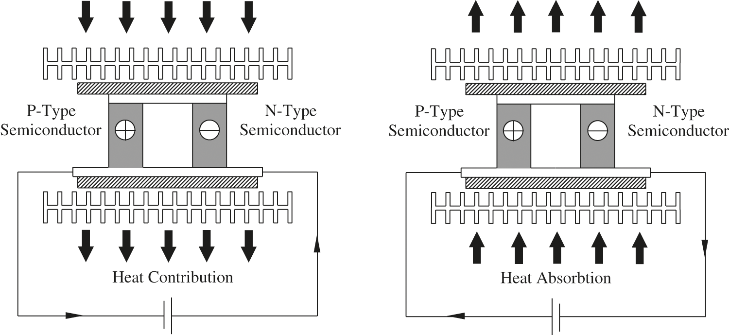
Figure 1: Peltier effect explained for both current directions
3 Modelling of Thermoelectric Self-Thermal Water System
In order to predict the performance of thermoelectric heating and cooling systems precisely, a proper modeling method is necessary. The thermodynamic model is simple and can predict the system performance precisely around the full load conditions.
4 Thermoelectric Self-Powered Water Supply System
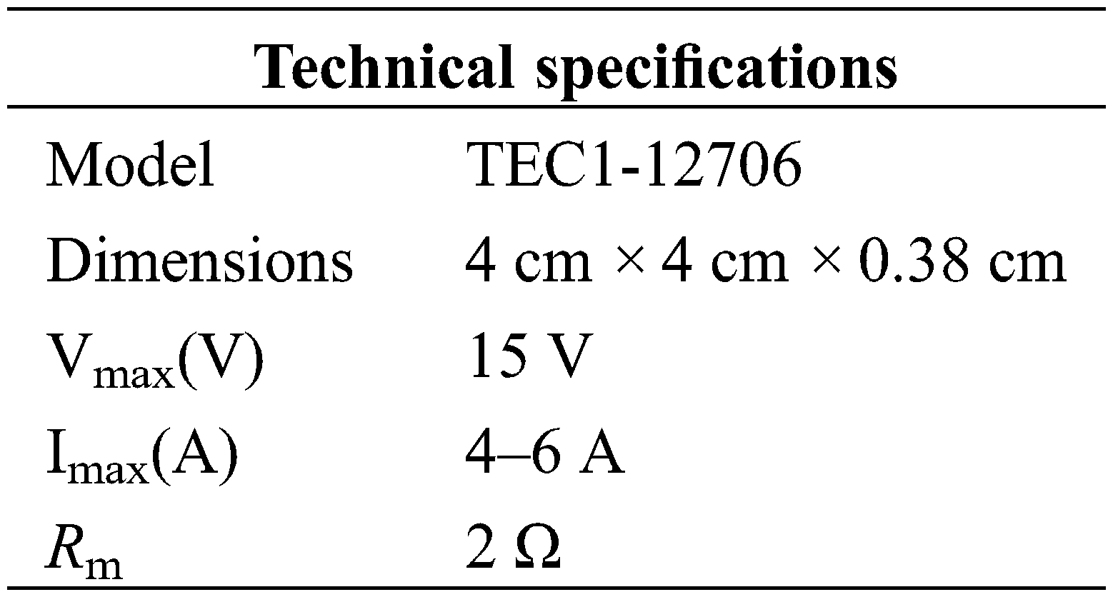
The thermoelectric self-powered water supply system is shown in Fig. 2. The system consists of circulating water tank, pumps, temperature, pressure and flow sensors, thermoelectric module, and heat exchangers. Two water channels from the tank containing room temperature water are heated in the casing heat exchanger through the thermoelectric module (semiconductor heat exchanger) to enter the shell and tube exchanger; the other way is then directly fed into the shell and tube heat exchanger at room temperature water. After the heat exchange in the shell tube heat exchanger, the cold fluid temperature increases, while the heated fluid temperature decreases. The lower temperature fluid return into the thermoelectric heat exchanger to recycle the low-grade energy and provide part of the energy for the heat production of the semiconductor heat exchanger. The cold fluid generated through the semiconductor heat pump is mixed with the low-temperature fluid flowing from the casing heat exchanger, flows into the tank, and further cooled with air to room temperature to maintain the smooth cycle. 12 V (max 6 A) 4 × 4 cm Peltier element is used in the system. The view and technical specifications of the Peltier element used are given in Fig. 3.
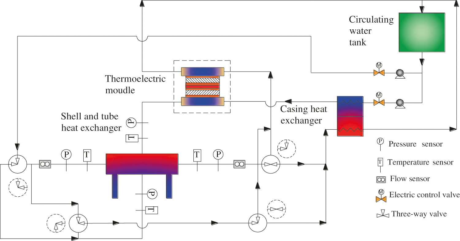
Figure 2: Flow chart of thermoelectric heating and cooling system
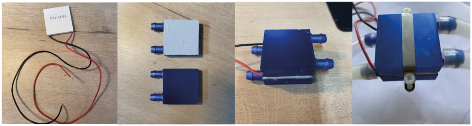
Figure 3: View and technical specifications of the peltier element
In this system, the laboratory design parameters were selected according to the local empirical values in Qingdao as follows: indoor ambient temperature T = 25°C in summer (T = 35°C when there is no air conditioner inside); ambient temperature T = 18°C in winter (T = 10°C when there is no air conditioner inside). What’s more, the temperature of water supply unit is adjustable between 5°C and 60°C; the volume of the circulating water tank is 0.2 L.
4.2 System Simulation in TRNSYS
The heating and cooling system with the thermoelectric module is mainly studied by simulation using the Transient System Simulation Program (TRNSYS), and the most distinctive feature of the system is the modular analysis approach. By modular analysis, it is considered that all heat transfer systems consist of several subsystems (i.e., modules). Every module implements a specific function, such as a water heater module, a single temperature field analysis module, and an output module, etc. Therefore, by calling the modules that implement these specific functions and given the input conditions, these module programs can simulate a particular heat transfer phenomenon and finally synthesize to perform transient simulation analysis of the whole system. As shown in Fig. 4, the gray block represents the component modules provided by the software, and the blue block represents the modules constructed in this study. All the TYP668 components in the system are the standard components which are featured below.
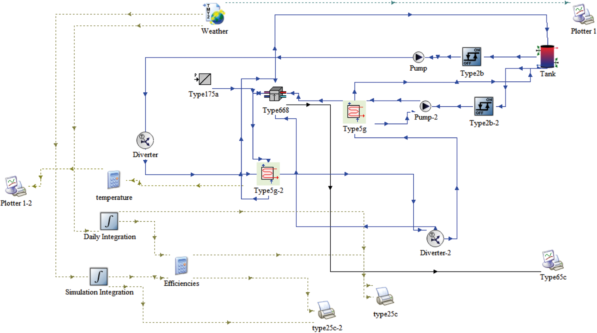
Figure 4: System simulation in TRNSYS
The weather data of the typical meteorological year in Qingdao are loaded in TYPE109-TMY2. The Qua calculator passes the input parameters directly to the output devices TYPE65d and TYPE25c. TYPE65d is used to determine whether the simulation can be interrupted immediately when the simulation is unreasonable.
The equation for the heat absorbed and released by Peltier can be found in [28], as in Eqs. (1)–(5).
where Sm, Rm, and Km are the Seebeck coefficient of the thermoelectric module, the electrical resistance of thermoelectric module total thermal conductance, and thermal conductance of thermoelectric generation module, respectively. I is the electrical current. Th and Tc are the hot and cold side temperatures, respectively. Because both the hot and cold sides of the thermoelectric module make contact and heat transfer with the water, the temperatures on two sides of the thermoelectric module can be regarded as the water temperatures when steady-state is reached. The rate of cooling and heating is determined by Eqs. (6) and (7).
Qr and Qa are the heat absorbed by the heat rejected to the hot water and cold water, respectively. Subscripts HW and CW denote the hot and cold water, respectively.
From an electrical point of view, the power generated by a thermoelectric unit can be calculated according to Eqs. (8)–(10).
Experimental results from Çağlar [27] for the simultaneous use of cooling and heating effects in the thermoelectric module to compare and verify the heat transfer temperature simulation in the proposed Trnsys model. For verification, the temperature difference between the cold and hot ends given by the experiment in case 1, when it reached at 1800 s, that is basically consistent with the conclusion of the model.
5.1 Temperature Effects from Varied Power Supply
The system was analyzed using software that simulates the system. The results are shown in Figs. 5 to 9 . The Wh and Wc are the temperature of the water on the hot and cold side, respectively.
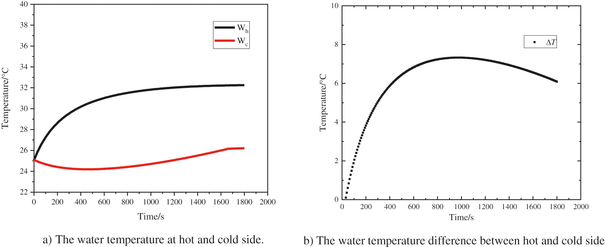
Figure 5: Temperature (a) and temperature difference (b) using 3 V, 1.5 A
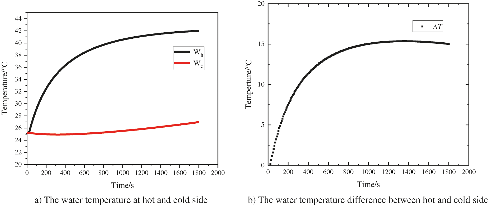
Figure 6: Temperature (a) and temperature difference (b) using 5 V, 3 A
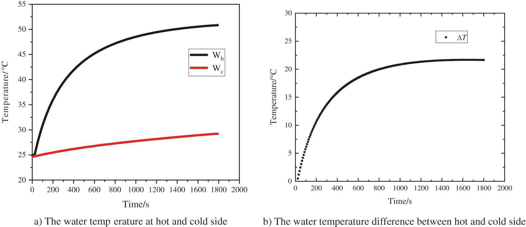
Figure 7: Temperature (a) and temperature difference (b) using 7 V, 3.5 A
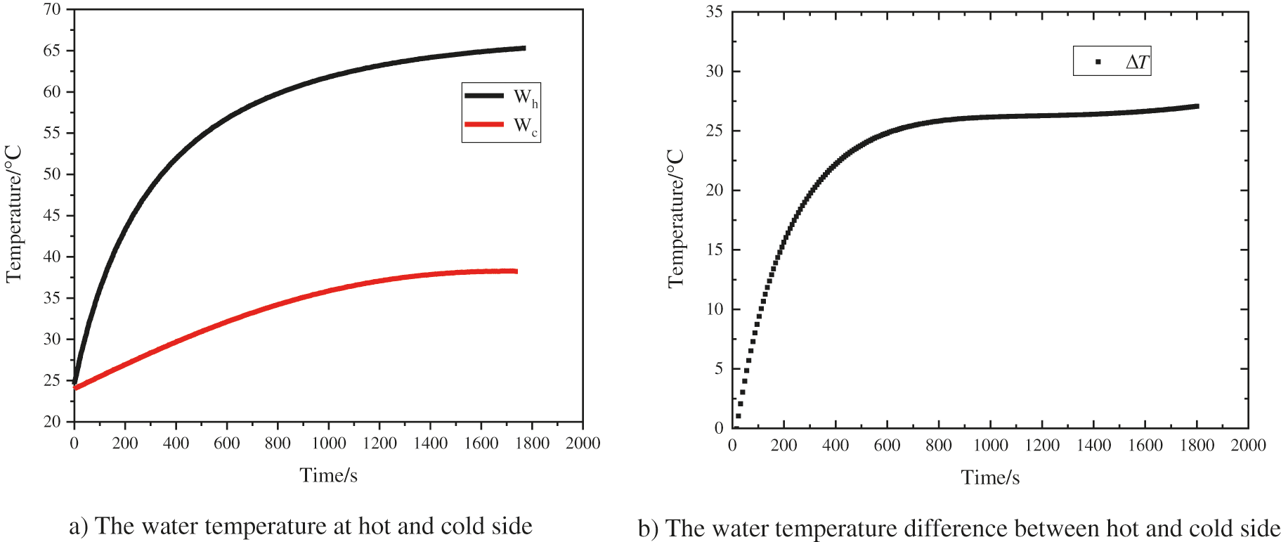
Figure 8: Temperature (a) and temperature (b) difference using 9 V, 4.5 A
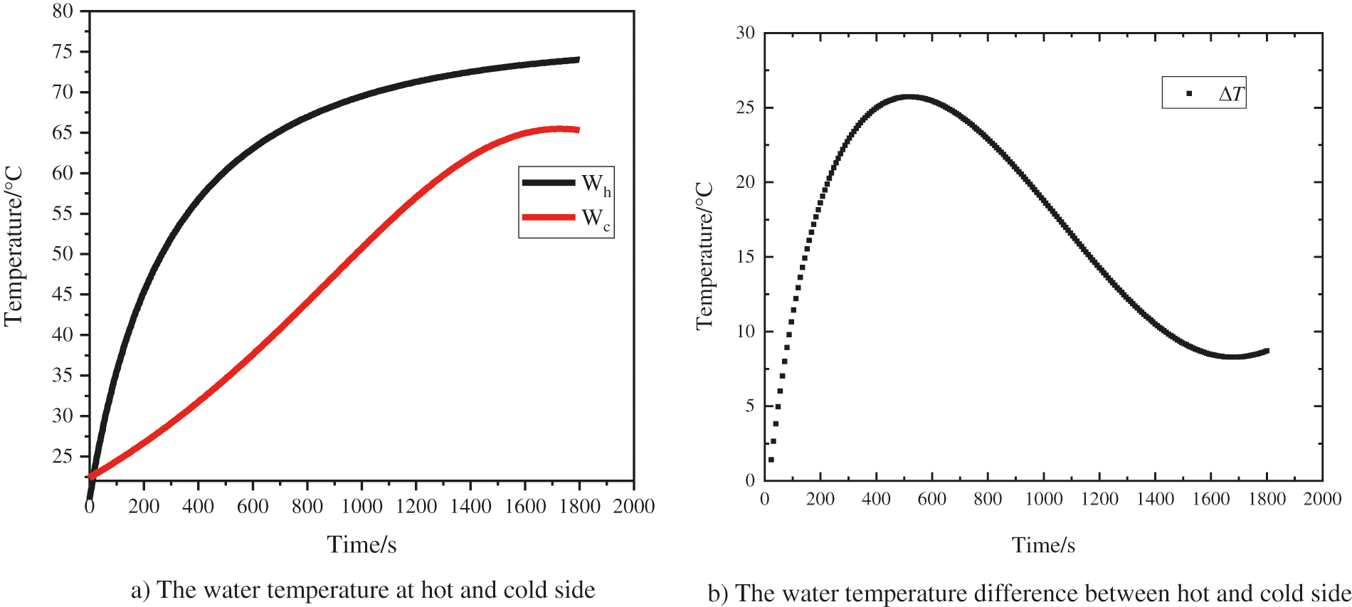
Figure 9: Temperature (a) and temperature difference (b) using 10 V, 5 A
The changing of water temperatures with time are plotted in Fig. 5, the thermoelectric module is provided with a voltage of 3 V and current of 1.5 A. At an initial temperature of 25°C, the water temperature presents different temperature changes in the two pipelines with true-time, demonstrating that two different operating conditions can be generated within the container using the thermoelectric module. However, maximum hot temperature only reached 32°C while the minimum cold temperature is 24°C with 3 V and 1.5 A (4.5 W). There is also a stable temperature difference between the hot and cold sides of water (ΔT) at 6°C–7.5°C around 10 min after the initiation of simulation and remains stable for the next 30 min. The heat generated by the thermoelectric module is not sufficient to produce a significant change in the gas-liquid equilibrium. Thus, it is required to increase the power supplied to the module.
The view of the second prototype of the system proposed is given in Fig. 6. The initial water temperature is still 25°C, while the power increases to 5 V and 3 A (15 W). After 30 min, the water temperature rises to about 42.5°C, which is expected to rise to a higher level. However, the thermal side temperature is higher and more applicable compared to the previous simulation. The temperature on cold side decreased in the first 10 min but increased over the remaining time. The temperature difference between the hot and cold sides was also increased to 14°C–15°C. It is shown that the thermal effect of thermoelectric module is more apparent with the power.
When the power is provided with 7 V, 3.5 A (24.5 W), the temperature change of the hot and cold current is shown in Fig. 7. The thermal side is more significant than that of 5 V, 3 A (15 W). However, at the same time, the temperature difference between hot and cold water is also further increasing. Fortunately, the hot temperature may rise and reach 52°C with a higher temperature difference at 22°C, but increased in the first 10 min grow with a faster rate. The cold side temperature showed a similar phenomenon while the speed of change is relatively slow.
This phenomenon has been occurred with a higher power supply, 9 V, 4.5 A (40.5 W) and 10 V, 5 A (50 W), as shown in Figs. 8 and 9. The temperature were higher on the hot side, 65°C and 75°C, and on the cold side, 37°Cand 63°C, respectively. Their temperature difference increased from 20°C to 27°C and decreased from 27°C to 25°C or even less.
A possible explanation of this phenomenon is the accumulation of heat and the design of the experimental device to obtain heat The ultimate aim is also to keep the thermal energy. On the other aspect, the energy supply to the thermoelectric module continues to provide external energy to the system. Although the thermoelectric module acts as a heat pump driving heat energy from one side to another side, additional heat accumulation requires more work and the module fails to provide more energy. Finally, heat flows from the cold side to the hot side by the law of thermodynamics. Even better, the thermoelectric module reaches 70°C and 75°C, for most composite vapor production by air-liquid balance (i.e., ethanol). However, it should be noted that there is still a problem with heat accumulation on the cold side, and it would be better if the cold side temperature, i.e., temperature of the ambient water is lower than 25°C.
5.2 Energy Conservation Analysis
The energy-saving effect of the system is reflected in two aspects, the energy saving of semiconductor power and the waste heat recovery of the system.
5.2.1 Energy Saving Analysis of Thermoelectric Module
This system is novel that the application of semiconductor modules in the water-water heat exchange experimental system can provide both cold and heat at the same time. By calculating the power consumption required by the system and comparing the energy required to heat the water to a specific temperature, 5 solutions are classified and discussed, namely case 1 (power supply 3 V, 1.5 A), case 2 (power supply 5 V, 3 A), case 3 (power supply 7 V, 3.5 A), case 4 (power supply 9 V, 4.5 A) and case 5 (power supply 10 V, 5 A). The water flow is controlled at 0.0005 kg/s.
This conclusion can also be gathered from Eqs. (8) and (12).
Firstly, the relationship between power consumption and heat transfer energy is analyzed. In Fig. 10, it can be found that when the heating reaches the same cold and hot temperature, the power of electric heating is always less than the required energy consumption. This also shows that under certain conditions, the use of electric heating makes the energy provided by semiconductors more energy-efficient than ordinary heating.
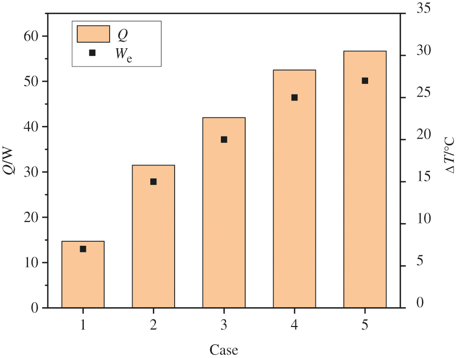
Figure 10: The relationship between We and Q under different conditions
5.2.2 System Waste Heat Recovery Analysis
The major advantage of this system is the design of the circulation channel, which avoids the need for water supply from the upper and lower sides, and makes great use of the waste heat recovery. Then, the thermodynamic performance of the energy flow of this system are analyzed.
Fig. 11 is a comparison of energy flow between ordinary electric water heaters and thermoelectric heat pump water heaters. It can be seen from Fig. 10 that there is a fundamental difference between the two pictures. In the figure, the meaning of each symbol is as follows: Q1, Q2, and Q3 represent the energy contained in the inlet water, the energy taken away by the drainage, and the heat dissipation loss of the system, respectively. We is the electric power consumed, Q4 is the energy of heat recovery. Analyze the energy flow, the definition of energy efficiency ratio (EER) can be calculated according to Eq. (12).
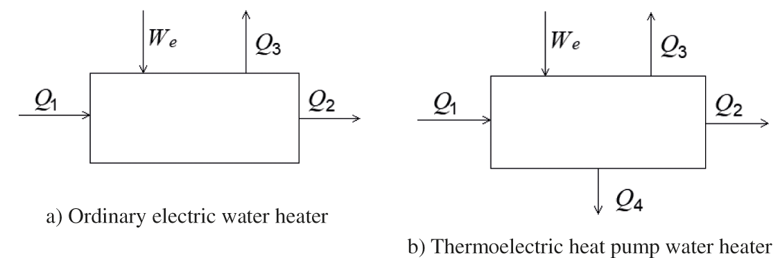
Figure 11: Comparison of energy flow between ordinary electric water heater and thermoelectric heat pump water heater
For an ordinary electric heating system, the EER can be calculated according to Eq. (13).
Because Q3 is always greater than 0, EER is less than or equal to 1. If all the electrical energy of an ordinary electric water heater is converted into heat energy, the energy efficiency depends on the heat loss of the water heater itself, mainly the heat loss Q3, so its energy efficiency is always less than 1.
For thermoelectric heat pump hot water system: the EER can be calculated according to Eq. (14).
For the thermoelectric heat pump hot water system, Q3 is mainly the heat dissipation loss of the hot water outlet pipe. Because the pipeline is short and the water temperature for self-powered heating is not too high, Q4 is greater than Q3, and EER > 1. So from the perspective of energy conservation, the energy conservation of heat pump water heaters depends on Q4 instead of Q3. Therefore, the drain temperature determines the energy-saving potential of the heat pump hot water system.
Studying the water system with thermoelectric module’s performance, the heat is sufficient to change the vapor-liquid equilibrium of most compounds from the thermal side. However, the problem lies on the cold side due to the heat build-up in the system, where the temperature is increased rather than lowered or kept at a lower temperature. Some of the proposed solutions to this problem are either by improving the performance of the thermoelectric module itself or by creating a mass and energy flow that removes excess heat from the system.
From the perspective of the entire system, the experimental system owns the advantage of small size, simple mechanical equipment and piping system, high-precision temperature control only by adjusting the input current. Based on the simulation results, some conclusions could be drawn as follows:
(1) After 30 min, the hot water temperature increased from 32°C to 75°C when the power increases from 4.5 to 50 W. The temperature rise was increased about 2 times.
(2) Under different test conditions, the power consumption of heating with thermoelectric modules is always about 22% less than the power consumption under the same conditions achieved by using electric heating alone.
(3) The waste heat recovery method is used to make the system more energy conservation to a certain extent.
(4) By increasing heat transferring stages, to solve the phenomenon that the temperature of the cold side gradually increases due to the heat accumulation in the system. The solution can be carried out in future studies, the results of which can be compared as further characterization studies of thermoelectric modules.
Data Availability Statement: The date that support the findings of this study are available from the corresponding author upon reasonable request.
Funding Statement: The authors received no specific funding for this study.
Conflicts of Interest: The authors declare that they have no conflicts of interest to report regarding the present study.
1. Luo, D., Wang, R., Yu, W., Zhou, W. (2021). A novel optimization method for thermoelectric module used in waste heat recovery. Energy Conversion and Management, 209, 112645. DOI 10.1016/j.enconman.2020.112645. [Google Scholar] [CrossRef]
2. Yu, Y., Zhu, W., Kong, X., Wang, Y., Zhu, P. et al. (2020). Recent development and application of thin-film thermoelectric cooler. Frontiers of Chemical Science and Engineering, 14(4), 492–503. DOI 10.1007/s11705-019-1829-9. [Google Scholar] [CrossRef]
3. Al-Nimr, M., Tashtoush, B., Jaradat, A. (2015). Modeling and simulation of thermoelectric device working as a heat pump and an electric generator under mediterranean climate. Energy, 90, 1239–1250. DOI 10.1016/j.energy.2015.06.090. [Google Scholar] [CrossRef]
4. Enescu, D., Virjoghe, E. (2014). A review on thermoelectric cooling parameters and performance. Renewable & Sustainable Energy Reviews, 38, 903–916. DOI 10.1016/j.rser.2014.07.045. [Google Scholar] [CrossRef]
5. Liu, Y., Lu, J., Wang, R., Wang, C., Jiang, J. (2020). Energy cooperation in quantum thermoelectric systems with multiple electric currents. Chinese Physics B, 29(4), 40504. DOI 10.1088/1674-1056/ab7da5. [Google Scholar] [CrossRef]
6. Khan, S., Kim, J., Acharya, S., Kim, W. (2021). Review on the operation of wearable sensors through body heat harvesting based on thermoelectric devices. Applied Physics Letters, 118(20), 200501. DOI 10.1063/5.0049347. [Google Scholar] [CrossRef]
7. Dargusch, M., Liu, W., Chen, Z. (2020). Thermoelectric generators: Alternative power supply for wearable electrocardiographic systems. Advanced Science, 7(18), 2001324. DOI 10.1002/advs.202001362. [Google Scholar] [CrossRef]
8. Goudarzi, A., Mozaffari, A., Samadian, P., Rezania, A., Rosendahl, L. (2014). Intelligent design of waste heat recovery systems using thermoelectric generators and optimization tools. Meccanica, 49(5), 1211–1223. DOI 10.1007/s11012-014-9878-0. [Google Scholar] [CrossRef]
9. Qing, S., Rezania, A., Rosendahl, L., Enkeshafi, A., Gou, X. (2018). Characteristics and parametric analysis of a novel flexible ink-based thermoelectric generator for human body sensor. Energy Conversion and Management, 156, 655–665. DOI 10.1016/j.enconman.2017.11.065. [Google Scholar] [CrossRef]
10. Kristiansen, N., Snyder, G., Nielsen, H., Rosendahl, L. (2012). Waste heat recovery from a marine waste incinerator using a thermoelectric generator. Journal of Electronic Materials, 41(6), 1024–1029. DOI 10.1007/s11664-012-2009-6. [Google Scholar] [CrossRef]
11. Elarusi, A., Attar, A., Lee, H. (2018). Analysis and experimental investigation of optimum design of thermoelectric cooling/heating system for car seat climate control (CSCC). Journal of Electronic Materials, 47(2), 1311–1321. DOI 10.1007/s11664-017-5854-5. [Google Scholar] [CrossRef]
12. Lim, H., Cheon, S., Jeong, J. (2018). Empirical analysis for the heat exchange effectiveness of a thermoelectric liquid cooling and heating unit. Energies, 11(3), 580. DOI 10.3390/en11030580. [Google Scholar] [CrossRef]
13. Ahammed, N., Asirvatham, L., Wongwises, S. (2016). Thermoelectric cooling of electronic devices with nanofluid in a multiport minichannel heat exchanger. Experimental Thermal and Fluid Science, 74, 81–90. DOI 10.1016/j.expthermflusci.2015.11.023. [Google Scholar] [CrossRef]
14. Chein, R., Chen, Y. (2005). Performances of thermoelectric cooler integrated with microchannel heat sinks. International Journal of Refrigeration, 28(6), 828–839. DOI 10.1016/j.ijrefrig.2005.02.001. [Google Scholar] [CrossRef]
15. Çağlar, A. (2018). Optimization of operational conditions for a thermoelectric refrigerator and its performance analysis at optimum conditions. International Journal of Refrigeration-Revue Internationale Du Froid, 96, 70–77. DOI 10.1016/j.ijrefrig.2018.09.014. [Google Scholar] [CrossRef]
16. Zhang, M., Miao, L., Kang, Y., Tanemura, S., Fisher, C. et al. (2013). Efficient, low-cost solar thermoelectric cogenerators comprising evacuated tubular solar collectors and thermoelectric modules. Applied Energy, 109, 51–59. DOI 10.1016/j.apenergy.2013.03.008. [Google Scholar] [CrossRef]
17. Cai, Y., Zhang, D., Liu, D., Zhao, F., Wang, H. (2019). Air source thermoelectric heat pump for simultaneous cold air delivery and hot water supply: Full modeling and performance evaluation. Renewable Energy, 130, 968–981. DOI 10.1016/j.renene.2018.07.007. [Google Scholar] [CrossRef]
18. Shen, Y., Zhao, B., Kwan, T., Yao, Q. (2020). Numerical analysis of combined air-cooled fuel cell waste heat and thermoelectric heating method for enhanced water heating. Energy Conversion and Management, 213, 112840. DOI 10.1016/j.enconman.2020.112840. [Google Scholar] [CrossRef]
19. Liu, D., Zhao, F., Yang, H., Tang, G. (2015). Theoretical and experimental investigations of thermoelectric heating system with multiple ventilation channels. Applied Energy, 159, 458–468. DOI 10.1016/j.apenergy.2015.08.125. [Google Scholar] [CrossRef]
20. Joshi, V., Joshi, V., Kothari, H., Mahajan, M., Chaudhari, M. et al. (2017). Experimental investigations on a portable fresh water generator using a thermoelectric cooler. International Conference on Recent Advancement in Air Conditioning and Refrigeration (RAAR), Bhubaneswar, India. DOI 10.1016/j.egypro.2017.03.085. [Google Scholar] [CrossRef]
21. Wang, S., Zhang, L., Liu, C., Liu, Z., Lan, S. et al. (2021). Techno-economic-environmental evaluation of a combined cooling heating and power system for gas turbine waste heat recovery. Energy, 231, 120956. DOI 10.1016/j.energy.2021.120956. [Google Scholar] [CrossRef]
22. Shoeibi, S., Rahbar, N., Esfahlani, A., Kargarsharifabad, H. (2020). Application of simultaneous thermoelectric cooling and heating to improve the performance of a solar still: An experimental study and exergy analysis. Applied Energy, 263, 114581. DOI 10.1016/j.apenergy.2020.114581. [Google Scholar] [CrossRef]
23. Yeler, O., Koseoglu, M. (2020). Optimization and experimental validation of a modular thermoelectric heat pump system for a premature baby Incubator. Journal of Electronic Materials, 49(6), 4053–4066. DOI 10.1007/s11664-020-08082-1. [Google Scholar] [CrossRef]
24. Lu, J. (2004). The development and performance analysis of thermoelectric heat pump heater, China (Master Thesis). College of Civil Engineering, Hunan University, China. [Google Scholar]
25. Allouhi, A., Boharb, A., Ratlamwala, T., Kousksou, T., Amine, M. et al. (2017). Dynamic analysis of a thermoelectric heating system for space heating in a continuous-occupancy office room. Applied Thermal Engineering, 113, 150–159. DOI 10.1016/j.applthermaleng.2016.11.001. [Google Scholar] [CrossRef]
26. Daghigh, R., Khaledian, Y. (2018). Effective design, theoretical and experimental assessment of a solar thermoelectric cooling-heating system. Solar Energy, 162, 561–572. DOI 10.1016/j.solener.2018.01.012. [Google Scholar] [CrossRef]
27. Çağlar, A. (2019). Design and experimental investigation of a novel thermoelectric water dispenser unit. Applied Thermal Engineering, 149, 822–828. DOI 10.1016/j.applthermaleng.2018.11.028. [Google Scholar] [CrossRef]
28. Zhang, H., Mui, Y., Tarin, M. (2010). Analysis of thermoelectric cooler performance for high power electronic packages. Applied Thermal Engineering, 30(6–7), 561–568. DOI 10.1016/j.applthermaleng.2009.10.020. [Google Scholar] [CrossRef]
29. Ibañez-Puy, M., Bermejo-Busto, J., Martín-Gómez, C., Vidaurre-Arbizu, M., Sacristán-Fernández, J. (2017). Thermoelectric cooling heating unit performance under real conditions. Applied Energy, 200, 303–314. DOI 10.1080/15435075.2013.829778. [Google Scholar] [CrossRef]
 | This work is licensed under a Creative Commons Attribution 4.0 International License, which permits unrestricted use, distribution, and reproduction in any medium, provided the original work is properly cited. |