

 | Journal of Renewable Materials |  |
DOI: 10.32604/jrm.2021.016304
ARTICLE
Improving the Dispersibility of Poly(urea-formaldehyde) Microcapsules for Self-Healing Coatings Using Preparation Process
College of Materials Science and Engineering, Nanjing Tech University, Nanjing, 211816, China
*Corresponding Author: Chengfei Zhu. Email: Njtechzhucf@163.com
Received: 24 February 2021; Accepted: 29 March 2021
Abstract: Poly(urea-formaldehyde) (PUF) microcapsules were prepared by in-situ polymerization with four different processes in this paper. The chemical composition, surface morphology, particle size distribution, and thermal stability were characterized by FTIR, SEM, particle size analyzer, and TGA, respectively. The results demonstrated that the agglomeration of the PUF microcapsules was related to the agglomeration of the emulsion particles caused by the changes of emulsion interface during the shell polymerization. Due to the slow deposition of the shell material, the PUF microcapsules with the core-shell structure prepared by the process with ammonium chloride as the last additive showed good dispersibility with an average diameter of 6.36 μm, high core content of 71.3 wt%, and high yield of 61.3 wt%. The PUF microcapsules had good thermal stability below 216°C. The PUF microcapsules could be uniformly dispersed in the epoxy coating in a single form. The epoxy coating with 2 wt% PUF microcapsules showed good self-healing property, and the service life of the coating was about doubled.
Keywords: In-situ polymerization; self-healing; microcapsules; anticorrosion; dispersibility; coatings
The life and performance of the polymer materials are usually improved by chemical modification [1–3] and additives. Microcapsule technology, by which solid, liquid and even gas can be encapsulated into micron particles, has attracted extensive attention of researchers [4]. The core material is separated from the environment by the shell and released under certain conditions. Using this mechanism, the material dispersed with microcapsules as additives can have certain self-healing properties. In 2001, White et al. [5] developed a kind of microcapsules containing dicyclopentadiene (DCPB) and added it to epoxy resin, which demonstrated that the microcapsules could heal the microcracks generated in the matrix and significantly restored the mechanical properties of the composite. After that, many microcapsule systems had been developed in decades [6,7]. The existing epoxy resin system had been confirmed to have good self-repairing abilities [8,9].
Urea-formaldehyde resin is the product of the polycondensation of urea and formaldehyde under acidic conditions and curing agent. Urea and formaldehyde are soluble but urea-formaldehyde resin is insoluble. Using this mechanism, urea-formaldehyde resin was widely used to encapsulate emulsion particles to form the poly(urea-formaldehyde) (PUF) microcapsules [8–16].
The PUF microcapsules were mainly synthesized via in-situ polymerization. The in-situ polymerization method, with the advantages of simple process, low cost, and easy industrialization, was first used as a microcapsule synthesis method in the 1980s and developed into industrial applications in the 1990s. But the particle size of the PUF microcapsules, usually reaching 100 μm [11–14,17,18], was too large for coatings. The particle size of the microcapsules had a great influence on the mechanical properties and self-healing abilities of the materials [19,20]. Excessively small and large microcapsules might be ineffective for healing the composites. Rule et al. [21] studied the effect of microcapsule size on the performance of self-healing polymers and demonstrated that the microcapsules with large particle size would have thick shell which adversely affected the self-healing properties for needing large local stress. Self-healing materials containing the microcapsules with smaller particle size could withstand greater loads. Considering the failure of the epoxy coating is caused by the breaking of the molecular bonds of the coating matrix, the coating could be repaired by the small microcapsules in the early stage of microcrack propagation.
The particle size and morphology of microcapsules prepared by in-situ polymerization depend not only on the type of core material and shell material but also on the reaction conditions such as the type of emulsifier, stirring speed, core/shell ratio, pH value, and reaction temperature [22]. Stacks of research papers had suggested that smaller emulsion particles could be obtained by increasing the emulsification rate [23–26]. In addition to the particle size, the dispersibility of the microcapsules was also an important factor in extending the life of the self-healing materials [10,11]. Agglomeration was a defect in the PUF microcapsules in our past study [8] and some related research [9,15,27]. Although the size of a single microcapsule was small, the actual size was large due to agglomeration, which was not conducive to the dispersion of microcapsules in the materials [28]. There are a few reports on the dispersion of microcapsules in recent years [10,29]. Some dispersants were used to improve the dispersion performance of microcapsules in materials. It was proven that better dispersion of microcapsules could improve the repair effect and reduce the amount of microcapsules. However, using dispersants was useless when the microcapsules could not be separated into individual particles, as shown in Fig. 1. Such problem often occurred in the PUF microcapsules with small particle size (less than 10 μm).
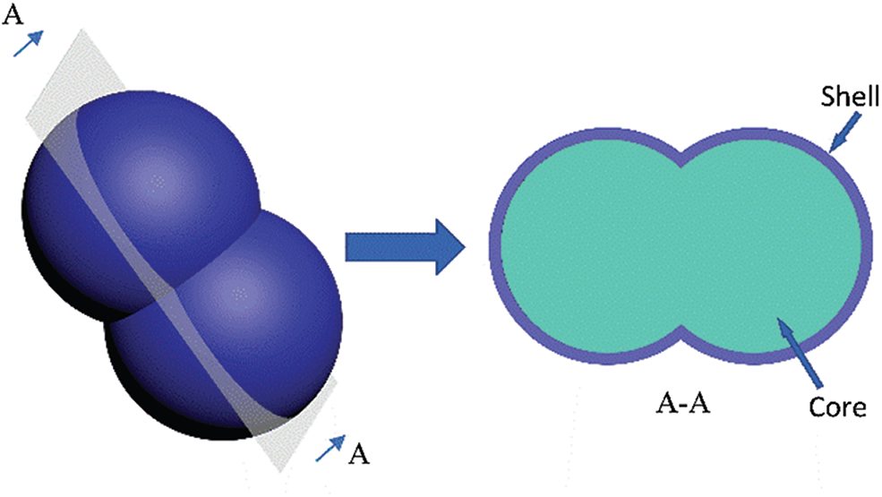
Figure 1: Schematic diagram of the agglomeration of the PUF microcapsules
In this paper, aimed at the agglomeration of the PUF microcapsules for coatings, Four processes were designed according to the order of the raw materials addition and studied the effect on the morphology of the PUF microcapsules, and successfully prepared PUF microcapsules with an average particle size of 6.36 μm. In addition, by observing the molding process of the shell and testing the pH in the process, the mechanism of the agglomeration was discussed.
2.1.1 Preparation of PUF Microcapsules
10.04 g urea (supplied by China Xilong Scientific Corporation, Shantou, China) was dissolved in 25.12 g 37 wt% formaldehyde solution (supplied by China Sinopharm Chemical Reagent Corporation, Beijing, China) and the pH was adjusted to 8.5 by triethanolamine (supplied by China Yonghua Chemical Technology Corporation, Shanghai, China). Then the solution was heated to 70°C for 1 h to transparent UF prepolymer.
The schematic diagram of the four preparation processes is shown in Fig. 2.
Step 1: 100 ml ultrapure water containing 1 wt% sodium dodecylbenzene sulfonate (SDBS, supplied by China Yonghua Chemical Technology Corporation, Shanghai, China) was prepared in a breaker, then 5 g epoxy resin (supplied by China Nantong Xingchen Synthetic Material Corporation, Nantong, China) was added and stirred at 1000 r/min for 1 h to obtain epoxy resin emulsion.1-octanol (0.1 g, supplied by China Sinopharm Chemical Reagent Corporation, Beijing, China) was added as a defoamer.
Step 2: Resorcinol (0.5 g, supplied by China Sinopharm Chemical Reagent Corporation), ammonium chloride (0.5 g, supplied by China Sinopharm Chemical Reagent Corporation, Beijing, China), and 9.26 g prepolymer were added, and the raw material addition sequences of the four different processes were shown in Tab. 1.
Step 3: The solution was added to a three-necked flask, then heated and maintained at 55°C. Meanwhile, one of resorcinol, ammonium chloride, and prepolymer was slowly added through a burette, and the pH was adjusted to about 3.5 by hydrochloric acid (supplied by China Sinopharm Chemical Reagent Corporation, Beijing, China). After four hours of reaction, the product could be obtained by filter and dry. All chemicals were used without further purification.
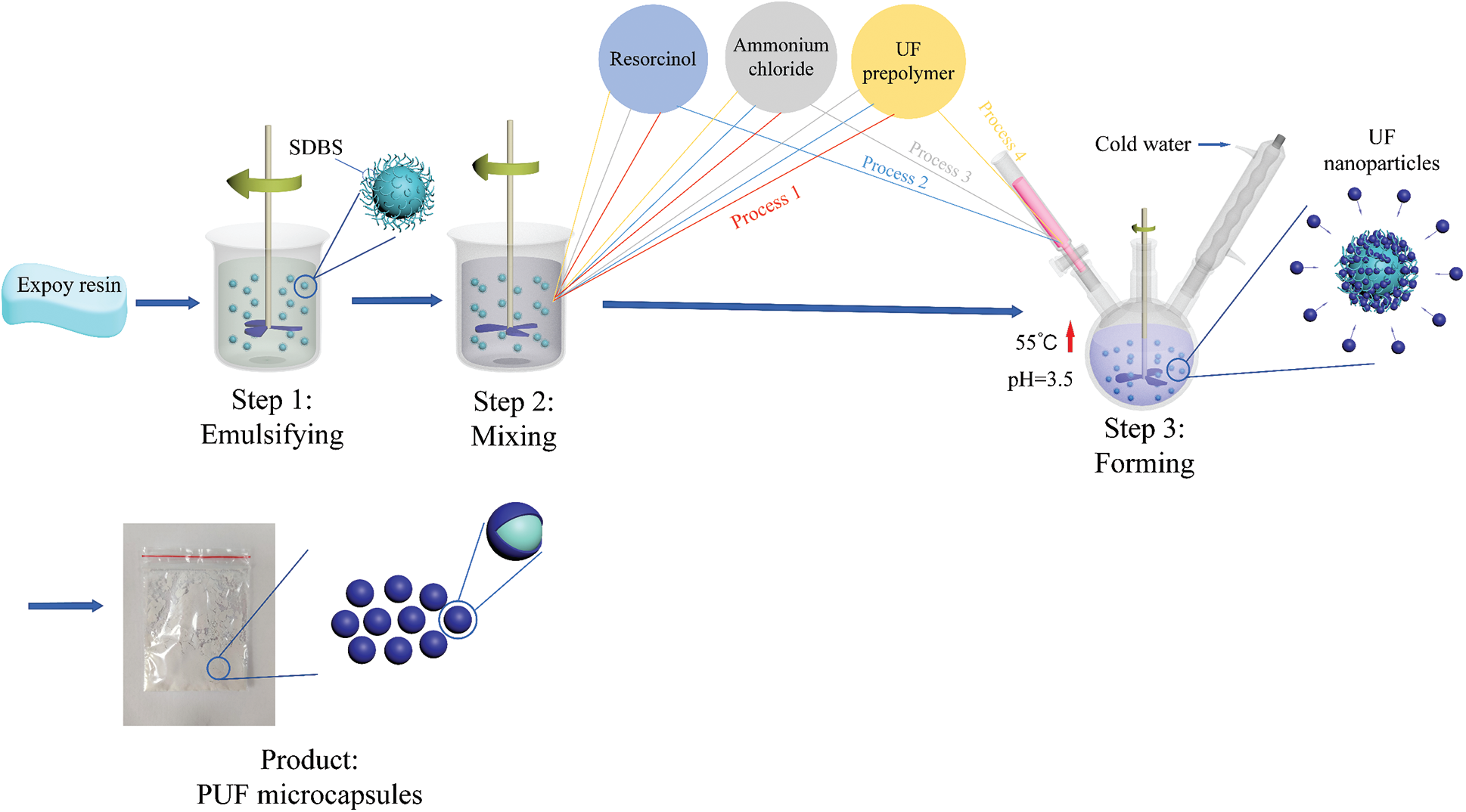
Figure 2: Schematic diagram of the four preparation processes of microcapsules

The PUF microcapsules (2 wt%, volume ratio: 8.2%) and 2-methylimidazole (1 wt%, China Sinopharm Chemical Reagent Corporation, Beijing, China) were added into HYDQ-01 coating (Jiujiang hengyu Painting Development Corporation, Jiujiang, China), and dispersed under ultrasonic wave. The microcapsule coating and the blank coating were coated on the surface of the carbon steel electrode, and were dried for two days. The thicknesses of the coatings were 80 ± 5 μm.
2.2.1 Characterization of PUF Microcapsules
The chemical structure of the microcapsules was characterized by Fourier transform infrared spectroscopy (FTIR, Thermo NIcolet AVATAR 600) with the wave range of 500∼4000 cm−1. The morphology was characterized by JSEM-6510 scanning electron microscope. The average particle sizes and particle size distribution were analyzed by Mastersizer 2000 Malvern laser particle size analyzer. The thermal stability was analyzed by NETZSCH STA 449C synchronous thermal analyzer, with the heating rate was maintained at 10°C/min in the temperature range of 40∼700°C. The pH of the emulsion was tested by PHS-3E pH meter manufactured by Thunder Magnetic.
The yield of the microcapsules was calculated through Eq. (1):
In the above equation, m1 and m2 were the quality of microcapsules product and the total solid content of the UF and the epoxy resin, respectively.
Some of the microcapsules were put into a mortar and fully ground, after cleaned and filtered with acetone, pure shell material could be obtained. The core content was calculated through Eq. (2):
In the above equation, m3 and m4 were the total mass of the microcapsules and the shell material quality.
2.2.2 Characterization of Coatings
The electrochemical impedance spectroscopy of the coatings was tested with an electrochemical workstation (Solartron 1287 and 1260). The frequency range was from 100 KHz to 0.01 Hz. The AC amplitude was 5 mV at the open-circuit potential.
The coating porosity (P) was calculated through Eq. (3) [30]:
In the above equation, Rc was the actual impedance of the coating, Ω•cm2; Rpt was the theoretical impedance of the coating with infinite porosity, Ω•cm2, usually calculated through Eq. (4) [30]:
In the above equation, d was the coating thickness, 80 μm; A was the coating area; 3.14 cm2; K was the dielectric conductivity, 3 × 10⁻² s/cm.
3.1 Characterization of Microcapsules
Fig. 3 shows the FTIR spectra of the PUF microcapsules prepared by the four processes. They were similar and the presence of strong peaks at 3375, 2970, 1650, 1560 cm−1 signified the stretching and vibrations of -O-H and -N-H groups, -C-H groups, -C=O groups, and -C-N groups, respectively, which were caused by the existence of PUF. The peaks of the epoxy group and benzene ring appeared at 912, 831 cm−1, and 1248, 1510 cm−1, which demonstrated the existence of the epoxy resin.
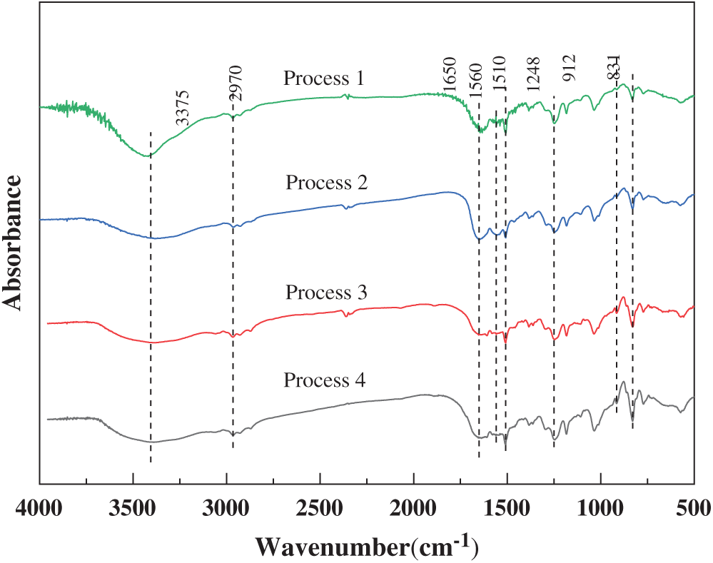
Figure 3: FTIR spectra of the PUF microcapsules prepared by the four processes
Fig. 4 shows the SEM micrographs of the PUF microcapsules prepared by the four processes. As shown in Fig. 4a, the PUF microcapsules were in the form of clusters and the diameter of an individual microcapsule was 1–4 μm. However, the PUF microcapsules stuck to each other to form PUF microcapsule clusters whose particle size far exceeded that of a single PUF microcapsule. According to the particle size distribution (Fig. 5a), the average particle size of the PUF microcapsule clusters was 42.3 μm. From Fig. 4b, the phenomenon of the agglomeration also existed. There was damage among the PUF microcapsules. There was a large number of PUF nano capsules with particle size of 500 nm. It could be seen that there were two small peaks at 0.7 and 7 μm in Fig. 5b and the D10 and D50 were 6.27, 52.9 μm, respectively. The PUF microcapsules prepared in Process 3 (Fig. 4c) were regular spherical with good dispersibility. Although there were still a few clusters formed, most PUF microcapsules had distinct, independent boundaries. Two peaks at 5 and 40 μm were obtained in Fig. 5c. The former corresponded to the SEM image and the latter illustrated the poor dispersion of some PUF microcapsules in the particle size test. The D10 and D50 were 6.36, 36.36 μm, respectively. The agglomeration of the PUF microcapsules prepared in Process 4 (Fig. 4d) was very serious. The size of the PUF microcapsule block was large according to Fig. 5d, and the average particle size was 114.8 μm.
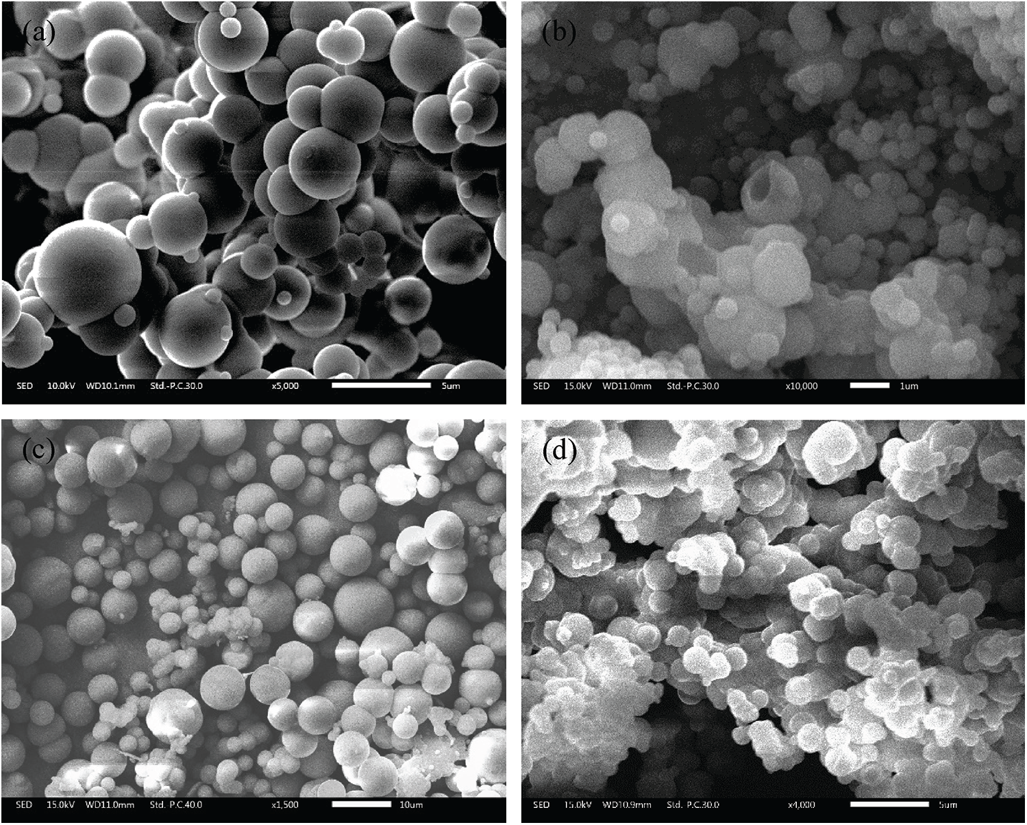
Figure 4: SEM micrographs of the PUF microcapsules prepared by the four processes: (a) Process 1; (b) Process 2; (c) Process 3; (d) Process 4
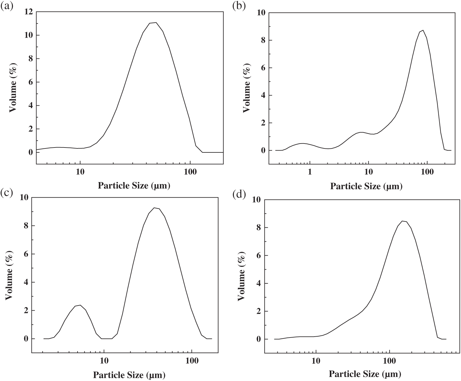
Figure 5: Particle size distribution of the PUF microcapsules prepared by the four processes: (a) Process 1;(b) Process 2; (c) Process 3; (d) Process 4
In the process of the four processes, we measured the pH value of the solution at each step, and the results are shown in Tab. 2. We found that the pH values were almost the same in Step 1 and Step 3, but different in Step 2 in the four processes. So we studied the effect of pH on the stability of the emulsion.

Fig. 6 is the morphology of the emulsion by an MR2000 optical microscope. As the value of pH dropped from 4.0 to 2.5, the density of the emulsion particles decreased. It was because the epoxy emulsion was a thermodynamically unstable multiphase dispersion system [31]. The short-term stability of the emulsion system was due to the interface between the emulsion particles and the water phase. The formation of this interface was related to the emulsifier (SDBS). The ionization reaction of SDBS in the water phase was shown in Eq. (5). R12 − Ph − was the lipophilic group which was dissolved in the epoxy, and

Figure 6: Effect of pH on the emulsion stability
The formation mechanism of the PUF microcapsules is as follows. When the pH decreased, the linear UF prepolymer began to polymerize and precipitated in the liquid phase, and subsequently deposited on the surface of the emulsion particles to form the shell [32]. Therefore, the stability of the emulsion was crucial during the formation process of PUF microcapsules. If the emulsion broke before the UF was deposited, the UF would not have enough emulsion particles to deposit. This would not only reduce the yield, but the UF precipitated in the system would also cause agglomeration of the PUF microcapsules.
In the raw materials for preparing the PUF microcapsules, the resorcinol was used as a modifier which could react with the hydroxyl in the methylolurea to increase the degree of adhesion of UF resin [33]. The water resistance of the shell was also improved because of the reduction in the number of hydroxyls. Ammonium chloride was used as a curing agent. It could react with the formaldehyde in the system (Eq. (7)). The polycondensation process of the UF prepolymer released formaldehyde, and the process was reversible. Therefore, the reduction of the formaldehyde promoted the polycondensation of the UF prepolymer. Additionally, the reaction and the hydrolysis of ammonium chloride (Eq. (8)) also produced HCl, which reduced the pH of the system and further drove the polycondensation of the prepolymer.
In Process 1, all the raw materials were mixed in Step 2. The prepolymer quickly deposited on the surface of the emulsion particles under the action of ammonium chloride, the stability of the interface was reduced, and the emulsion particles were coalesced. The prepolymer was further deposited on the surface of the aggregated particles, forming the PUF microcapsule clusters with poor dispersion. In Process 2, the cause of the agglomeration was the same as Process 1. Besides, the resorcinol did not react with the UF resin until the final stage, which reduced the strength of the shell. In Process 3, the ammonium chloride was added slowly in Step 3, the UF resin precipitated and slowly aggregated on the surface of the emulsion particles. The resorcinol in the system increased the degree of cross-linking of the shell material. Therefore, the microcapsules had better dispersibility and better integrity. In Process 4, the UF prepolymer added in Step 3 cured in a short time due to the ammonium chloride and the low pH, which caused lots of core material particles to be encapsulated together rapidly.
The PUF microcapsules obtained in Process 3 had good dispersibility. Based on the above pH analysis, the rate of decrease in pH value of the Process 3 was the slowest. The UF slowly deposited on the surface of the emulsion particles to form a UF film. Since the thin UF film had not yet solidified, the lipophilic groups in the emulsifier were adsorbed in it. The hydrophilic groups were adsorbed in the liquid phase to form a new negatively charged interface. The new interface prevented the collisions between the microcapsules. With the gradual curing of the UF film, the aggregation of microcapsules was prevented.
Fig. 7 shows the SEM image of the damaged PUF microcapsules prepared in Process 3 as well as the corresponding infrared spectrum. The PUF microcapsule with a diameter of 5.5 μm lost the epoxy resin inside and only left the outer shell with a thickness of 210 nm. And the corresponding FTIR spectrum shows the characteristic peak of the PUF but no related peaks of the epoxy resin. So the microcapsules had a core-shell structure with the shell of PUF, and the core of epoxy resin.
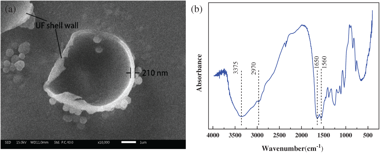
Figure 7: (a) SEM image and (b) FTIR spectrum of the PUF microcapsules shell (Process 3)
The yield and core content of the PUF microcapsules prepared by the four Processes are reported in Fig. 8. It was the highest yield of 61.3% and the highest core content of 71.9 wt% in Process 3. The lowest yield of only 32.6% and lowest core content of 53.6 wt% appeared in Process 4. The yield of the microcapsules depended on the reaction efficiency. Demulsification of the emulsion caused the epoxy to deposit on the bottom and could not be encapsulated into the PUF microcapsules, which led to the waste of the raw materials and reduced the yield. The core content was related to the shell thickness and the UF impurities in the microcapsules. When the particles reduced, the excess UF in the system became impurities and made the shell thicker. The thinner shell thickness and the lower impurity content resulted in the higher core content of the microcapsules. Therefore, the particle content was the highest and the PUF impurities was the least in Process 3.
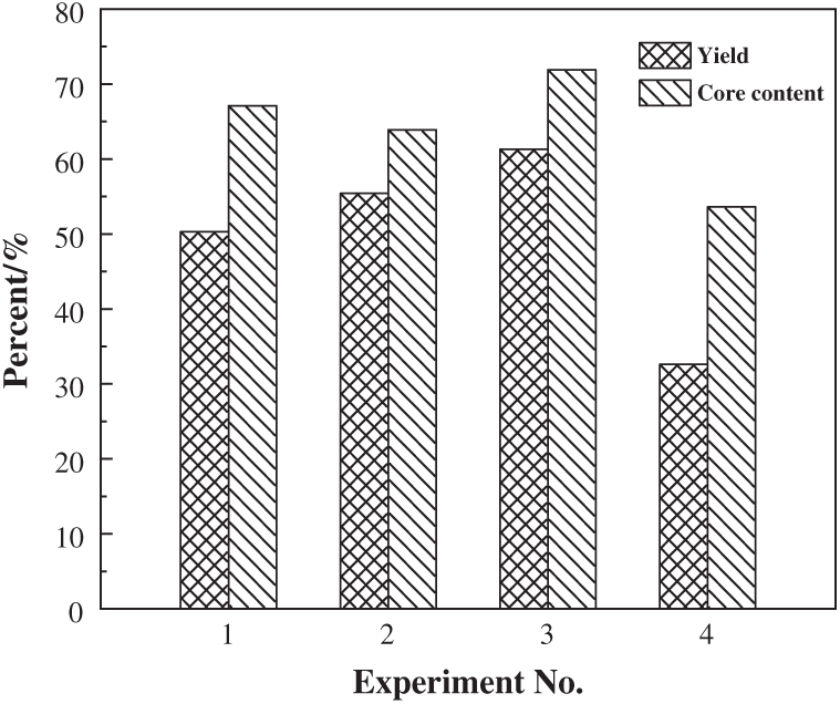
Figure 8: Yield and core content of the PUF microcapsules prepared by the four Processes
The TG curves for the PUF microcapsules of Process 3 and the corresponding UF shell is shown in Fig. 9. The PUF microcapsules and UF shell shows a mass loss of 7.8 wt% and 8.6 wt% at about 60°C, which was mainly caused by the evaporation of small molecules such as water, alcohol, formaldehyde and the decomposition of some impurities. The PUF microcapsules and the UF shell began to decompose at 216°C and 186°C. There was a characteristic peak at 350°C on the TG curve of the PUF microcapsules, which was caused by the decomposition of the core material. The microcapsules and UF shell lost approximately 76% and 95% of their total initial weight at the end of the thermal analysis. So, the PUF microcapsules showed good thermal stability with the thermal stability temperature of about 216°C.
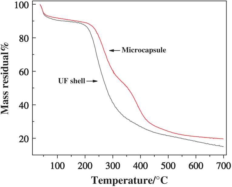
Figure 9: TG curves of the UF shell and the PUF microcapsules of Process 3
3.2 Characterization of Coatings
The PUF microcapsules prepared in Process 3 were used to prepare smart epoxy coatings, and the dispersibility in the coatings and self-repairing properties were tested. And the electrochemical impedance (EIS) test was used to evaluate the influence of the microcapsules on the life of the coatings.
The cross-sectional OM image of epoxy coating with 2 wt% microcapsules is shown in Fig. 10a. It could be seen that the PUF microcapsules were uniformly dispersed in the coating in the form of a single existence. The complete PUF microcapsules and the left UF shells after the broken of the PUF microcapsules could also be seen. Two artificial scratches on the surface of the blank epoxy coating and the microcapsules epoxy coating were observed. As shown in Fig. 10b and Fig. 10c, the scratch on the former was almost unchanged, but the scratch on the later was filled with the core material. When the scratch passed through the microcapsules in the matrix, the internal epoxy resin filled in the scratches under the action of the capillary effect and then cured. The reaction equation of the self-healing behavior is shown in Fig. 11.
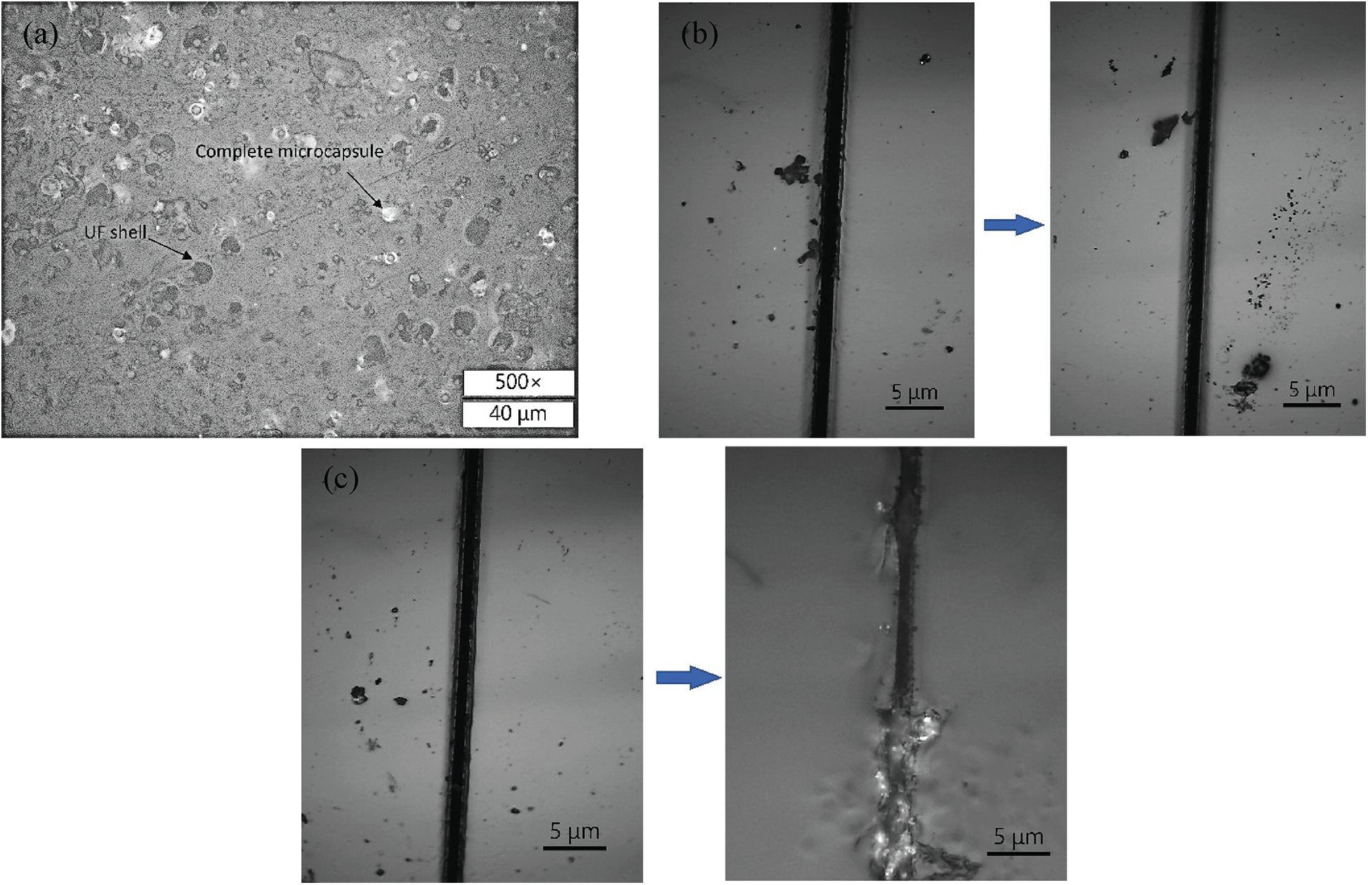
Figure 10: (a) Cross-sectional image of the epoxy coating with 2 wt% dispersed PUF microcapsules (Process 3); (b) Changes in the artificial scratch of the blank epoxy coating after 6 h; (c) Changes in the artificial scratch of the epoxy coating with 2 wt% dispersed PUF microcapsules after 6 h

Figure 11: The reaction equation of the self-healing behavior
From Fig. 12, the initial impedances of both the coatings had reached 108 Ω·cm2, which shows that the two coatings could effectively prevent the penetration of corrosive media in the initial stage of immersion [34]. With the extension of the experiment time, the impedance of both the coatings continued to decrease. During this period of time, a large number of micropores were generated on the surface of the coatings due to the swelling of the epoxy resin coating and the volatilization of the organic solvents [16]. The corrosive media penetrated from these micropores. As of 35 d, the impedance of the blank coating was reduced to 1.28 × 10⁵ Ω·cm2. Generally, when the impedance of the coating dropped below 106 Ω·cm2, the coating was considered to be invalid, and the corrosive medium had been in contact with the substrate [34,35]. The impedance of the coating with microcapsules dropped to 9.73 × 10⁵ Ω·cm2 at 70 d. The molecular bonds in the coating were broken and microcracks were gradually formed. The merging and propagation of the micro-cracks made the coating gradually fail. In the process of the microcapsule coating failure, when the microcracks contacted the microcapsules, the shell cracked under the action of the local stress. The core material started to fill the microcracks and cured under the action of the latent curing agent, which slowed the failure rate of the coating.
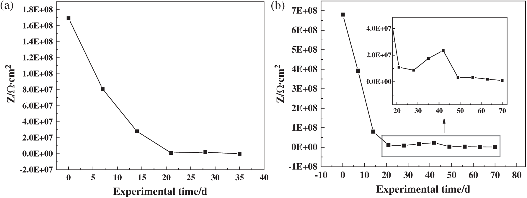
Figure 12: Curves of the impedance of the coatings/carbon steel systems in seawater with different immersion time: (a) blank epoxy coating; (b) epoxy coating with 2 wt% PUF microcapsules
In order to further study the influence of the microcapsules on the failure rate of the coatings, the porosity (P) during the failure process of the coating was calculated, and the logP-T fitting diagrams was made, as shown in Fig. 13. The intercept of the fitted line represented the initial impermeability of the coating. The coatings with smaller intercept had the better initial impermeability. The slope represented the failure rate. The intercepts of the blank coating and the microcapsule coating were 5.550 and 5.461, and the difference was less than 2%, indicating that the initial impermeability of the two coatings was basically the same. The slope of the epoxy coating was 0.037, which was smaller than that of the blank coating (0.108), indicating that the microcapsules could significantly reduce the failure rate of the epoxy coating.
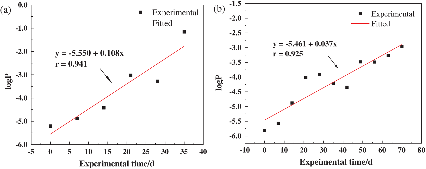
Figure 13: logP-t curves of the coating/carbon steel systems in seawater with different immersion time: (a) blank epoxy coating; (b) epoxy coating with 2 wt% PUF microcapsules
PUF microcapsules with good dispersibility for self-healing coatings were successfully prepared. When the ammonium chloride was used as the final additive, the pH of the emulsion system dropped most slowly during the synthesis of the PUF microcapsules, resulting in the slowest shell material deposition rate on the emulsion particles, and the PUF microcapsules had the best dispersibility, high yield of 61.3%, and high core content of 71.9 wt%. The core-shell structure of the PUF microcapsules was verified. The PUF microcapsules had good thermal stability below 216°C. Finally, the PUF microcapsules with the particle size of about 6.13 μm could be uniformly dispersed in the coating in a single form. The epoxy coating with 2 wt% PUF microcapsules showed good self-healing property, and the service life of the coating prolonged about double.
Funding Statement: This work was supported by the Jiangsu National Synergetic Innovation Center for Advanced Materials and the Priority Academic Program Development of Jiangsu Higher Education Institutions.
Conflicts of Interest: The authors declare that they have no conflicts of interest to report regarding the present study.
1. Jia, P. Y., Song, F., Li, Q. G., Xia, H. Y., Li, M. et al. (2019). Recent development of cardanol based polymer materials—A review. Journal of Renewable Materials, 7(7), 601–619. DOI 10.32604/jrm.2019.07011. [Google Scholar] [CrossRef]
2. Li, Q. G., Shu, X. G., Jia, P. Y., Zhou, Y. H. (2020). Preparation of biomass-based ester end-capped hyperbranched poly(ether)s via facile one-pot reaction and their performance as non-toxic plasticizers. Polymers, 12(4), 1–11. DOI 10.3390/polym12040913. [Google Scholar] [CrossRef]
3. Yang, X. X., Li, Q. G., Li, Z. S., Xu, X., Liu, H. et al. (2019). Preparation and characterization of room-temperature-vulcanized silicone rubber using acrylpimaric acid-modified aminopropyltriethoxysilane as a cross-linking agent. ACS Sustainable Chemistry & Engineering, 7(5), 4964–4974. DOI 10.1021/acssuschemeng.8b05597. [Google Scholar] [CrossRef]
4. Keller, M. W., White, S. R., Sottos, N. R. (2007). A self-healing poly(dimethyl siloxane) elastomer. Advanced Functional Materials, 17(14), 2399–2404. DOI 10.1002/adfm.200700086. [Google Scholar] [CrossRef]
5. White, S. R., Sottos, N. R., Geubelle, P. H., Moore, J. S., Kessler, M. R. et al. (2002). Autonomic healing of polymer composites, Nature, 409, 794–797. DOI 10.1038/415817a. [Google Scholar] [CrossRef]
6. Wool, R. P. (2008). Self-healing materials: A review. Soft Matter, 4(3), 400–418. DOI 10.1039/b711716g. [Google Scholar] [CrossRef]
7. An, S., Lee, M. W., Yarin, A. L., Yoon, S. S. (2018). A review on corrosion-protective extrinsic self-healing: Comparison of microcapsule-based systems and those based on core-shell vascular networks. Chemical Engineering Journal, 344, 206–220. DOI 10.1016/j.cej.2018.03.040. [Google Scholar] [CrossRef]
8. Yao, J. L., Yang, C. P., Zhu, C. F., Hou, B. Q. (2019). Preparation process of epoxy resin microcapsules for self-healing coatings. Progress in Organic Coatings, 132, 440–444. DOI 10.1016/j.porgcoat.2019.04.015. [Google Scholar] [CrossRef]
9. Cosco, S., Ambrogi, V., Musto, P., Carfagna, C. (2007). Properties of poly(urea-formaldheyde) microcapsules containing an epoxy resin. Journal of Applied Polymer Science, 105(3), 1400–1411. DOI 10.1002/(ISSN)1097-4628. [Google Scholar] [CrossRef]
10. Yu, H. C., Zhang, Y. T., Wang, M. J., Li, C. C. (2019). Dispersion of poly(urea-formaldehyde)-based microcapsules for self-healing and anticorrosion applications. Langmuir, 35(24), 7871–7878. DOI 10.1021/acs.langmuir.9b00526. [Google Scholar] [CrossRef]
11. Yan, X. X., Chang, Y. J., Qian, X. Y. (2019). Preparation and self-repairing properties of urea formaldehyde-coated epoxy resin microcapsules. International Journal of Polymer Science, 2019, 1–11. DOI 10.1155/2019/7215783. [Google Scholar] [CrossRef]
12. Tzavidi, S., Zotiadis, C., Porfyris, A., Korres, D. M., Vouyiouka, S. (2020). Epoxy loaded poly(urea-formaldehyde) microcapsules via in situ polymerization designated for self-healing coatings. Journal of Applied Polymer Science, 137(43), 1–11. DOI 10.1002/app.49323. [Google Scholar] [CrossRef]
13. Li, H. Y., Wang, R. G., Hu, H. L., Liu, W. B. (2008). Surface modification of self-healing poly(urea-formaldehyde) microcapsules using silane-coupling agent. Applied Surface Science, 255(5), 1894–1900. DOI 10.1016/j.apsusc.2008.06.170. [Google Scholar] [CrossRef]
14. Yuan, L., Gu, A. J., Liang, G. Z. (2008). Preparation and properties of poly(urea-formaldehyde) microcapsules filled with epoxy resins. Materials Chemistry and Physics, 110(2–3), 417–425. DOI 10.1016/j.matchemphys.2008.02.035. [Google Scholar] [CrossRef]
15. Yan, X. X., Wang, L., Qian, X. Y. (2019). Effect of urea-formaldehyde-coated epoxy microcapsule modification on gloss, toughness and chromatic distortion of acrylic copolymers waterborne coating. Toughness and Chromatic Distortion of Acrylic Copolymers Waterborne Coating, 9(4). DOI 10.3390/coatings9040239. [Google Scholar] [CrossRef]
16. Yuan, L., Liang, G. Z., Xie, J. Q., Li, L., Guo, J. (2006). Preparation and characterization of poly(urea-formaldehyde) microcapsules filled with epoxy resins. Polymer, 47(15), 5338–5349. DOI 10.1016/j.polymer.2006.05.051. [Google Scholar] [CrossRef]
17. Blaiszik, B. J., Caruso, M. M., McIlroy, D. A., Moore, J. S., White, S. R. et al. (2009). Microcapsules filled with reactive solutions for self-healing materials. Polymer, 50(4), 990–997. DOI 10.1016/j.polymer.2008.12.040. [Google Scholar] [CrossRef]
18. Vintila, I. S., Iovu, H., Alcea, A., Cucuruz, A., Mandoc, A. C. et al. (2020). The synthetization and analysis of dicyclopentadiene and ethylidene-norbornene microcapsule systems. Polymers (Basel12(5). DOI 10.3390/polym12051052. [Google Scholar] [CrossRef]
19. Su, J. F., Wang, X. Y., Dong, H. (2012). Micromechanical properties of melamine-formaldehyde microcapsules by nanoindentation: Effect of size and shell thickness. Materials Letters, 89, 1–4. DOI 10.1016/j.matlet.2012.08.072. [Google Scholar] [CrossRef]
20. Keller, M. W., Sottos, N. R. (2006). Mechanical properties of microcapsules used in a self-healing polymer. Experimental Mechanics, 46(6), 725–733. DOI 10.1007/s11340-006-9659-3. [Google Scholar] [CrossRef]
21. Rule, J. D., Sottos, N. R., White, S. R. (2007). Effect of microcapsule size on the performance of self-healing polymers. Polymer, 48(12), 3520–3529. DOI 10.1016/j.polymer.2007.04.008. [Google Scholar] [CrossRef]
22. Zhu, D. Y., Rong, M. Z., Zhang, M. Q. (2015). Self-healing polymeric materials based on microencapsulated healing agents: From design to preparation. Progress in Polymer Science, 49–50, 175–220. DOI 10.1016/j.progpolymsci.2015.07.002. [Google Scholar] [CrossRef]
23. Li, Q., Mishra, A. K., Kim, N. H., Kuila, T., Lau, K. T. et al. (2013). Effects of processing conditions of poly(methylmethacrylate) encapsulated liquid curing agent on the properties of self-healing composites. Composites Part B-Engineering, 49, 6–15. DOI 10.1016/j.compositesb.2013.01.011. [Google Scholar] [CrossRef]
24. Zhu, D. Y., Rong, M. Z., Zhang, M. Q. (2013). Preparation and characterization of multilayered microcapsule-like microreactor for self-healing polymers. Polymer, 54(16), 4227–4236. DOI 10.1016/j.polymer.2013.06.014. [Google Scholar] [CrossRef]
25. Meng, L. M., Yuan, Y. C., Rong, M. Z., Zhang, M. Q. (2010). A dual mechanism single-component self-healing strategy for polymers. Journal of Materials Chemistry, 20(29), 6030–6038. DOI 10.1039/c0jm00268b. [Google Scholar] [CrossRef]
26. Yuan, Y. C., Rong, M. Z., Zhang, M. Q. (2008). Preparation and characterization of microencapsulated polythiol. Polymer, 49(10), 2531–2541. DOI 10.1016/j.polymer.2008.03.044. [Google Scholar] [CrossRef]
27. Safaei, F., Khorasani, S. N., Rahnama, H., Neisiany, R. E., Koochaki, M. S. (2018). Single microcapsules containing epoxy healing agent used for development in the fabrication of cost efficient self-healing epoxy coating. Progress in Organic Coatings, 114, 40–46. DOI 10.1016/j.porgcoat.2017.09.019. [Google Scholar] [CrossRef]
28. Tezel, Ö., Çiğil, A. B., Kahraman, M. V. (2019). Design and development of self-healing coating based on thiol–epoxy reactions. Reactive and Functional Polymers, 142, 69–76. DOI 10.1016/j.reactfunctpolym.2019.06.004. [Google Scholar] [CrossRef]
29. Pedaballi, S., Li, C. C., Song, Y. J. (2019). Dispersion of microcapsules for the improved thermochromic performance of smart coatings. Rsc Advances, 9(42), 24175–24183. DOI 10.1039/C9RA04740A. [Google Scholar] [CrossRef]
30. Cao, C. (2008). Corrosion electrochemistry. China: Chemical Industry Press. [Google Scholar]
31. Liu, J. Y., Chen, G. M., Ren, X. H., Zhou, F. (2018). Analysis of emulsification effect of emulsifier on epoxy resin E51. Functional Materials, 5(49), 05202–05215. DOI 10.3969/j.issn.1001-9731.2018.05.035. [Google Scholar] [CrossRef]
32. Fan, C. J., Tang, J. T., Zhou, X. D. (2013). Role of ammonium chloride in preparing poly(urea-formaldehyde) microcapsules using one-step method. Journal of Applied Polymer Science, 129(5), 2848–2856. DOI 10.1002/app.39008. [Google Scholar] [CrossRef]
33. Wang, X. G., Xu, W., Xie, Y. H., Yao, H., Xia, L. (2019). Improving particle characteristic and encapsulated indicators of urea-formaldehyde/epoxy self-healing microcapsule by incorporating resorcinol. Materials Technology, 34(2), 51–58. DOI 10.1080/10667857.2018.1522474. [Google Scholar] [CrossRef]
34. Coniglio, N., Nguyen, K., Kurji, R., Gamboa, E. (2013). Characterizing water sorption in 100% solids epoxy coatings. Progress in Organic Coatings, 76(9), 1168–1177. DOI 10.1016/j.porgcoat.2013.03.011. [Google Scholar] [CrossRef]
35. Zhang, J. T., Hu, J. M., Zhang, J. Q., Cao, C. N. (2004). Studies of water transport behavior and impedance models of epoxy-coated metals in NaCl solution by EIS. Progress in Organic Coatings, 51(2), 145–151. DOI 10.1016/j.porgcoat.2004.08.001. [Google Scholar] [CrossRef]
 | This work is licensed under a Creative Commons Attribution 4.0 International License, which permits unrestricted use, distribution, and reproduction in any medium, provided the original work is properly cited. |