
 Submit a Paper
 Propose a Special lssue
 Open Access
ARTICLE

Synthesis and Characterization of CMC-Wrapped ZnONPs at Different Calcination Temperatures for Photocatalytic Degradation of Methylene Blue Dye under Sunlight
Department of Chemistry, Guru Ghasidas Vishwavidyalaya, Bilaspur, Chhattisgarh, 495009, India
* Corresponding Authors: Subhash Banerjee. Email: ; Arti Srivastava. Email:
Journal of Polymer Materials 2024, 41(2), 69-86. https://doi.org/10.32604/jpm.2024.052695
Received 11 April 2024; Accepted 10 July 2024; Issue published 09 August 2024
 View Full Text
 Download PDF
Abstract
This study aims to synthesize, characterize, and evaluate the photocatalytic efficiency of carboxymethyl cellulose (CMC) wrapped ZnONPs for the degradation of methylene blue (MB) dye under sunlight and also focuses on the effect of varying calcination temperatures on crystallite size of the synthesized ZnONPs@CMC. It focuses on developing biopolymer (CMC) wrapped ZnO nanoparticles (ZnONPs@CMC) at different calcination temperatures. ZnONPs@CMC are synthesized using zinc acetate dihydrate as a precursor under alkaline conditions, followed by adding capping agent CMC at various calcination temperatures ranging from 250°C to 650°C. The nanomaterials are characterized by UV-Vis, FTIR, and powder X-Ray Diffraction (XRD) studies. The presence of CMC as a capping agent facilitates the nucleation and growth of nanoparticles (NPs) and provides stability and functionalization to the NPs. The varying calcination temperature plays a significant role in influencing the size of NPs during the synthesis process. The crystallite size of ZnO-CMC NPs is 19.5959, 21.2518, 23.5000, 27.5930, and 34.9789 nm at 250°C, 350°C, 450°C, 550°C, and 650°C calcination temperature, respectively. With the increase in the calcination temperature from 250°C to 650°C, crystallite size increased significantly. The degradation of MB dye is studied using a UV-visible spectrophotometer, revealing that the synthesized ZnONPs@CMC are highly efficient in the photocatalytic degradation of MB under sunlight.Keywords
Due to their unique properties, smart materials have become crucial in many applied fields. Nanoparticles (NPs) are particularly notable for their enhanced physical, chemical, and biological capabilities, with applications in electronics, energy, medicine, environmental cleanup, and materials research. Nanoparticles are used in medicine for drug delivery, imaging, and diagnostics [1,2]. They are also employed in electronics and optoelectronics [3], environmental sensing and remediation, energy storage and conversion, and advanced materials [4,5].
Nanoparticles are especially suitable for targeted drug delivery and imaging, enhancing treatment efficacy while reducing side effects [6,7]. Their large surface area and reactivity make them ideal for environmental cleanup, where they degrade and remove contaminants from soil, water, and air [8,9]. Reinforcing materials with NPs can improve hardness, wear resistance, and mechanical strength [10]. In addition, NPs can enhance materials’ optical, thermal, and electrical properties, leading to advanced functional materials. In energy applications, NPs improve the performance of batteries and fuel cells [11] and are used in solar cells to increase efficiency.
Several treatments, such as physical, chemical, and biological, have been tested to remove dyes from the aquatic environment [12,13]. Physical adsorption, which requires minimal energy, is exceptionally effective, easy to use, and suited for a wide range of applications, has received the most attention [14–16]. Pollutants are moved from the liquid phase to the adsorbent’s exterior surface using the adsorption process, resulting in secondary pollution. Hence, contaminants cannot be entirely removed by the adsorption process. Other significant problems with this approach include its limited capacity for adsorption and the challenge of renewing the adsorbent for further usage. In this regard, a new trend in removing organic pollutants, particularly in degrading dyes, is the use of adsorption-photocatalysis technology. Under this method, the adsorbent absorbs the pollutants first, and the photocatalytic reaction transforms them into non-toxic or mineralized forms. Organic molecules can be selectively degraded by highly reactive free radicals that are the basis of photocatalytic degradation. Eliminating water pollutants is most successful using photocatalysts with excellent adsorption performance and high percentage photocatalytic destruction efficiency [17].
Metal oxide nanoparticles, such as ZnONPs, are valued for their superior properties compared to bulk materials and are also widely used in the photodegradation of dyes from polluted water. ZnONPs have antimicrobial and antifungal properties, making them suitable for medical applications such as wound healing and infection prevention [14]. They are also used in sunscreens and cosmetics for UV protection [15], gas sensors [16], catalysts in chemical processes [17], and devices like LEDs and solar cells [18]. In addition, zinc oxide nanoparticles (ZnONPs) are being extensively investigated for their potential anticancer effects. Their unique properties allow them to effectively target and kill cancer cells, offering a promising alternative to traditional cancer treatments. ZnONPs showed significant antibacterial activity, particularly against drug-resistant bacteria. This makes them a valuable tool in the fight against bacterial infections that do not respond to conventional antibiotics [19–24].
Carboxymethyl cellulose (CMC) (Fig. 1) is a water-soluble polymer derived from cellulose, known for its high water solubility, stability, and ability to form films. It is used as an emulsifier [25], thickening agent [26], stabilizer [27], and in biomedical applications due to its non-toxicity and biocompatibility [28,29]. CMC also stabilizes NPs in aqueous solutions, preventing aggregation [30]. The anionic CMC can remove methylene blue (MB) by electrostatic attraction [31], which impacts zinc oxide’s (ZnO) combination adsorption and photocatalytic properties. There are two ways in which this can happen. First, ZnO’s photocatalytic and crystallinity characteristics can be impacted by CMC. Based on research by Qin et al. [32], ZnO’s sensitivity to UV radiation increases when it is encapsulated in polyvinyl alcohol (PVA). During the process, free radicals are produced that can break down CMC, reducing the ability of ZnO coated with CMC to break down MB. Reactive oxygen species (ROS), triggered by UV-irradiated ZnO, are primarily responsible for the breakdown of MB. Examples of ROS include superoxide (·O2−) and hydroxyl (·OH) radicals [33].
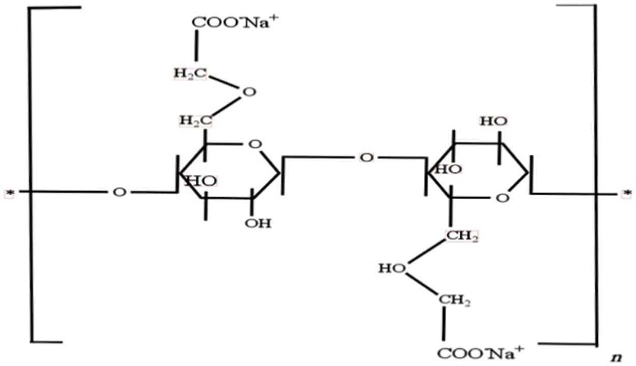
Figure 1: Structure of CMC
MB, a toxic and carcinogenic dye, contaminates industrial wastewater, posing significant environmental and health risks [34]. Developing effective methods to remove MB is essential. Various techniques for synthesizing ZnONPs include sol-gel processes [35], precipitation [36], hydrothermal synthesis [37], microwave-assisted methods [38], solvothermal synthesis [39], and electrochemical methods [40]. These methods enable the production of ZnONPs with properties suitable for applications such as photocatalytic degradation of pollutants, contributing to environmental cleanup and resource sustainability. Experiments using a UV-visible spectrophotometer indicated that synthesized ZnONPs coated with CMC are highly effective at breaking MB dye when exposed to natural sunlight. This study investigates the photocatalytic degradation of MB using CMC-wrapped ZnONPs under direct sunlight to better understand how different calcination temperatures affect this process.
The chemicals, zinc acetate dihydrate (Zn(CH3COO)22H2O), sodium hydroxide (NaOH), methylene blue (C16H18CIN3S), sodium carboxymethyl cellulose, and ethanol were purchased from Himedia Chemicals, Bilaspur, India, and are of analytical grade. All the chemicals were used without further purification, and their solutions were prepared in double distilled water.
2.2 Synthesis of Biopolymer CMC-Wrapped ZnO Nanoparticle
CMC-capped ZnO nanoparticles were synthesised by a precipitation technique. First, 6.58 g of zinc acetate dihydrate was dissolved in 100 mL of double-distilled water. NaOH solution (1.2 g in 100 ml of distilled water) was added dropwise while stirring continuously until a white Zn(OH)2 suspension formed. Separately, 1 g of CMC was dissolved in 100 mL of distilled water, added to the mixture dropwise, and stirred for 2 h. The product was rinsed with distilled water and ethanol before drying at 60°C. Calcination was performed for 3 h at 250°C, followed by cycles at 350°C, 450°C, 550°C, and 650°C (Fig. 2).
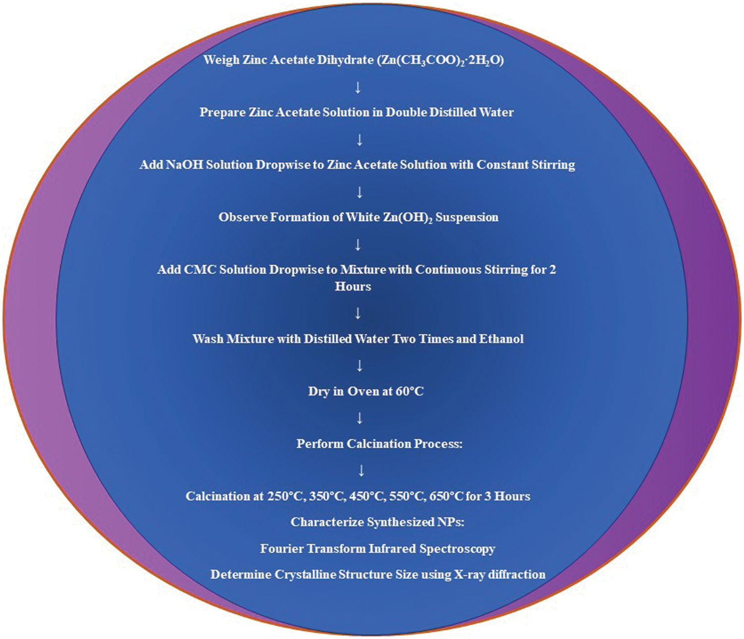
Figure 2: Flow chart showing the synthesis of CMC-wrapped ZnONPs
2.3 Reaction Involved in ZnONPs Formation
The overall reaction for the formation of ZnONPs from zinc acetate dihydrate and sodium hydroxide can be summarized as follows:
Different characterization techniques were employed to characterize the synthesized NPs using FTIR. The crystalline structure size was determined through XRD.
2.4 Method of Photodegradation
The 5 ppm MB dye solution was prepared by dissolving 0.0005 g of methylene blue in 100 mL of distilled water, and photocatalytic degradation of MB dye was performed on various ZnONPs @CMC samples calcinated at different temperatures. The specific amount, i.e., 0.02 g of the synthesized CMC-capped ZnONPs, was added to 5.0 mL MB solution and mixed thoroughly to ensure uniform dispersion. Then, the dye solution containing synthesized CMC-capped ZnONPs was exposed to sunlight for a particular duration. The sample was collected regularly during the exposure to monitor the degradation progress using a UV vis spectrophotometer.
2.5 Characterization Techniques
The FTIR spectra of all the samples were recorded using a model Bruker Alpha II FTIR spectrometer manufactured in Billerica, MA, USA to confirm the formation of ZnONPS using CMC. Peaks related to both ZnONPs and CMC components were observed.
XRD is a potent method for examining nanomaterials’ crystallographic characteristics and revealing details of their atomic structure and particle size. The finely powdered ZnO-CMC NP samples are subjected to X-ray radiation using a Bruker D8 Advance (Eco) XRD machine manufactured in Germany. Analyzing the positions, intensities, and width of the diffraction peaks of XRD spectra of the ZnONPs@CMC provides information about the average crystallite size of the ZnO NPs. The size of the ZnONPs@CMC is calculated using the Debye-Scherrer equation.
The UV-1800 model, Shimadzu, a UV spectrophotometer manufactured in Kyoto, Japan, was employed to analyze the photocatalytic degradation of dye.
The samples of ZnONPs@CMC synthesized at various calcination temperatures were represented in Fig. 3, and the FTIR spectra of synthesized ZnONPs@CMC at varying calcination temperatures viz. 250°C, 350°C, 450°C, 550°C, and 650°C are shown in Fig. 4. The peak between 560 and 680 cm−1 in all spectra is due to the formation of Zn-O, which becomes sharp at higher calcination temperatures, showing the transformation of Zn(OH)2 to ZnO [41]. The small peaks observed between 3500 to 3700 cm−1 are assigned to O-H stretching vibration, which signifies the hygroscopic nature of ZnO that becomes small with increasing calcination temperature and disappears at higher calcination temperatures, i.e., 650°C [42–45]. The peaks at 2800 cm−1 show the C-H stretching [43], which are sharper at higher calcination temperatures, and the peaks around 1600 to 1700 cm−1 indicate C=O stretching vibrations [44], and these peaks correspond to the presence of CMC as capping during synthesis of ZnONPs.
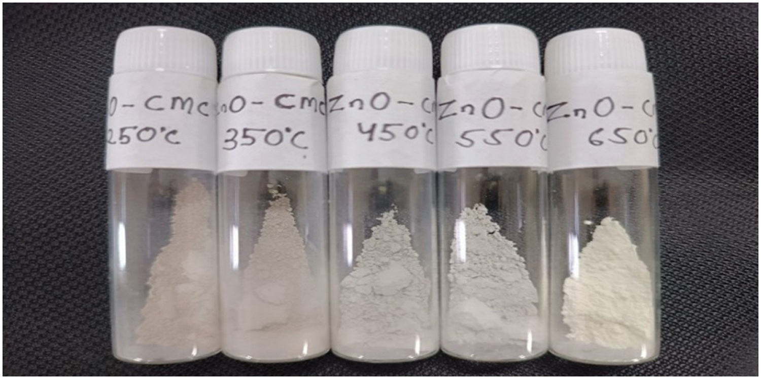
Figure 3: Synthesized ZnONPs @CMC samples at various calcination temperatures
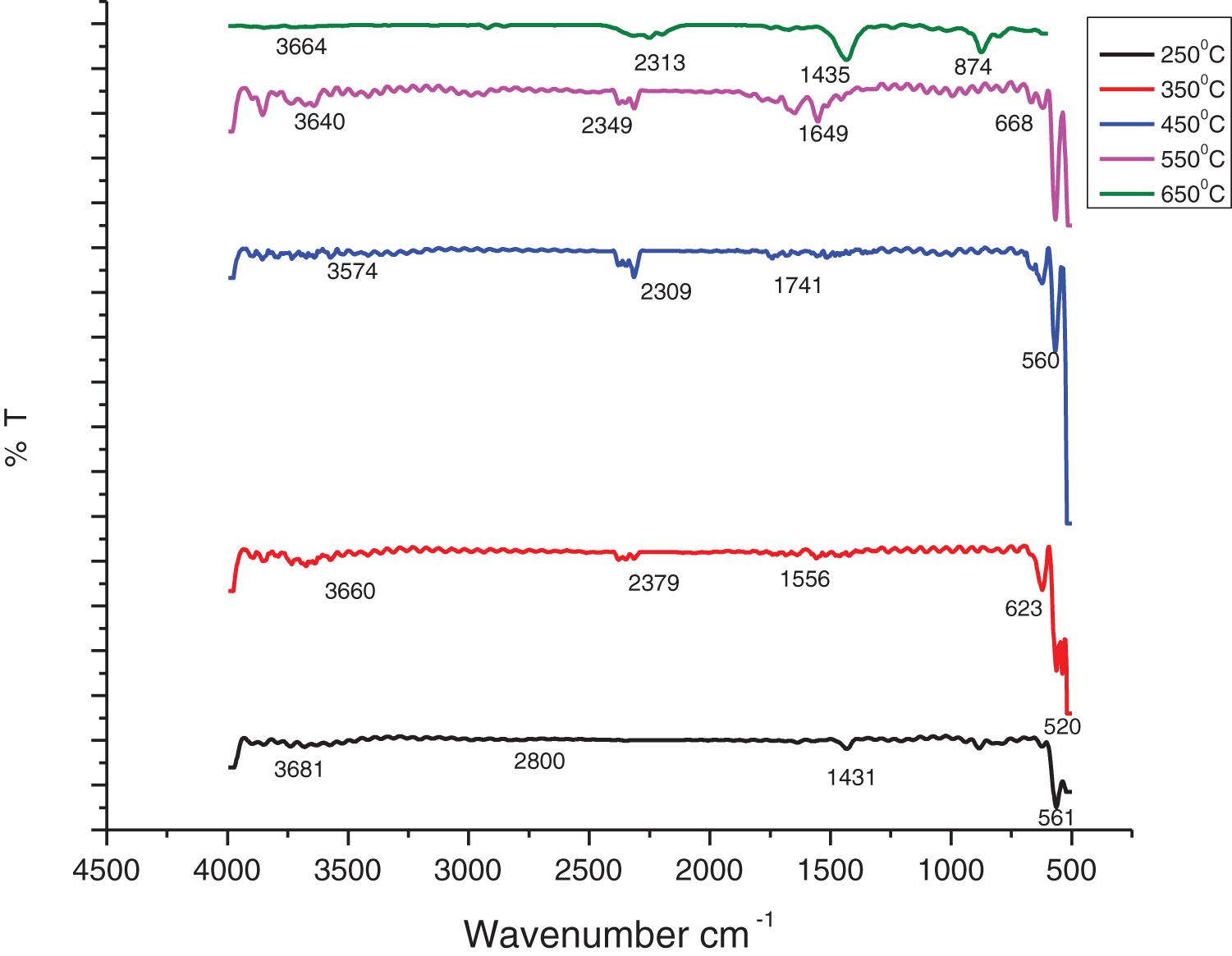
Figure 4: FTIR spectra of ZnONPs @CMC at different calcination temperatures
The XRD spectra pattern of the ZnONPs @CMC at different calcination temperaturesare shown in Figs. 5 through 9. The XRD data are utilized to calculate the average crystallite size of CMC-ZnO NPs. The Debye-Scherrer method was employed to estimate the size of crystallites. The Debye-Scherrer equation is described as follows:
where
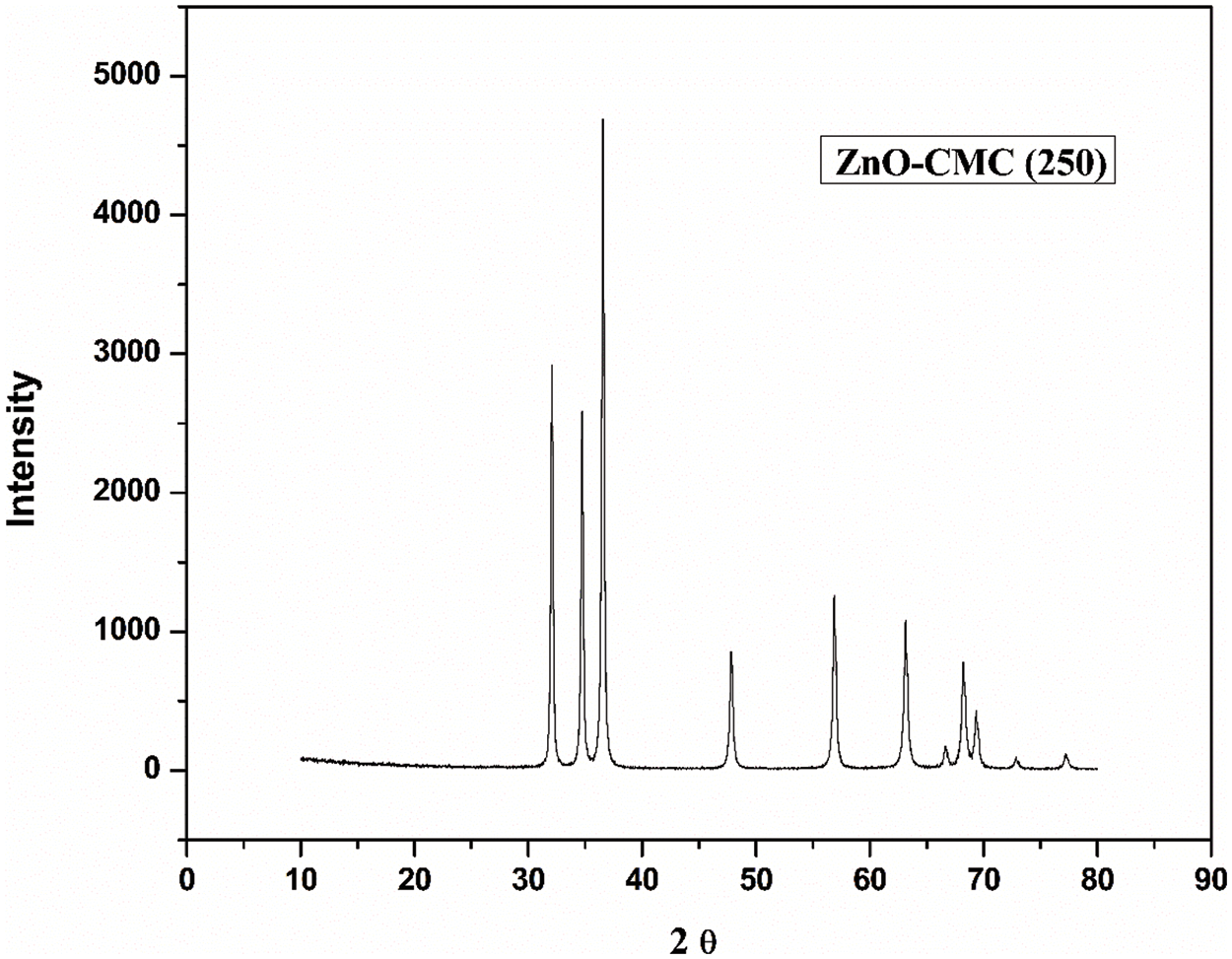
Figure 5: XRD spectra of ZnONPs@CMC calcinated at 250°C

Figure 6: XRD spectra of ZnONPs@CMC calcinated at 350°C
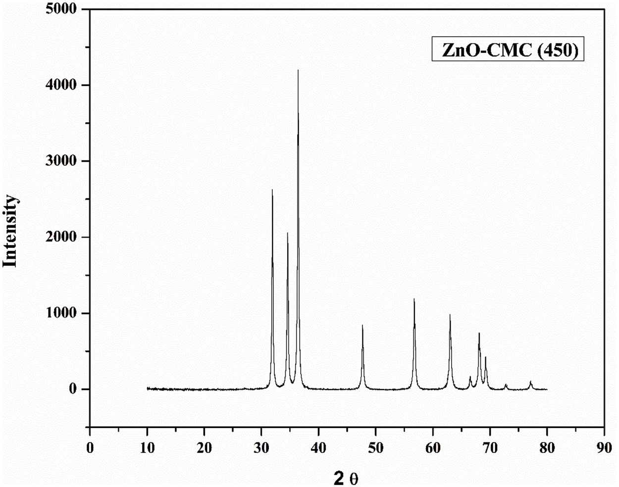
Figure 7: XRD spectra of ZnONPs@CMC calcinated at 450°C

Figure 8: XRD spectra of ZnONPs@CMC calcinated at 550°C
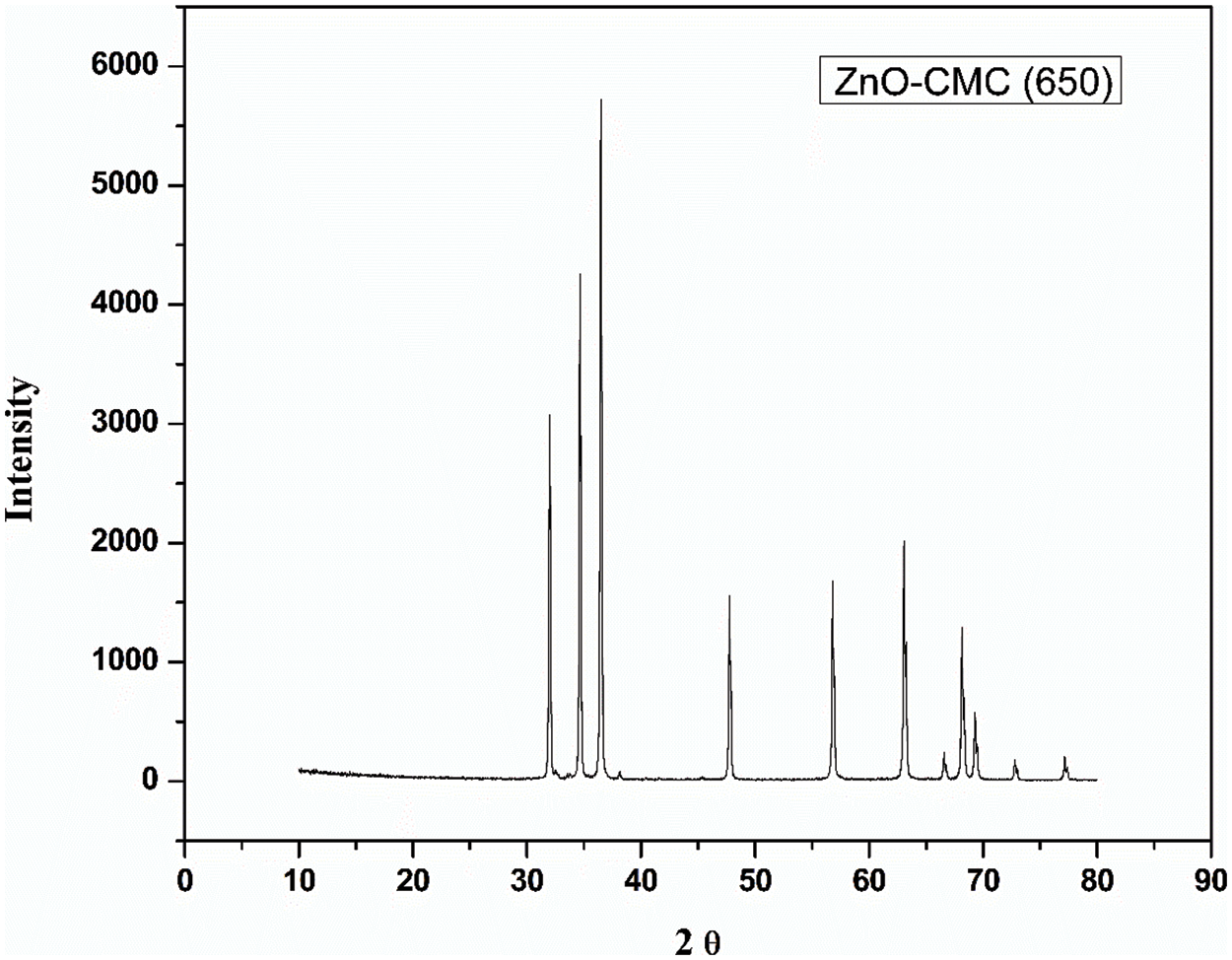
Figure 9: XRD spectra of ZnONPs@CMC calcinated at 650°C
D is the crystallite size in nm
K is the Scherrer constant (0.9)
β is the full-width half maximum (FWHM) of diffraction (in radians)
θ is the Bragg’s angle (in radians)
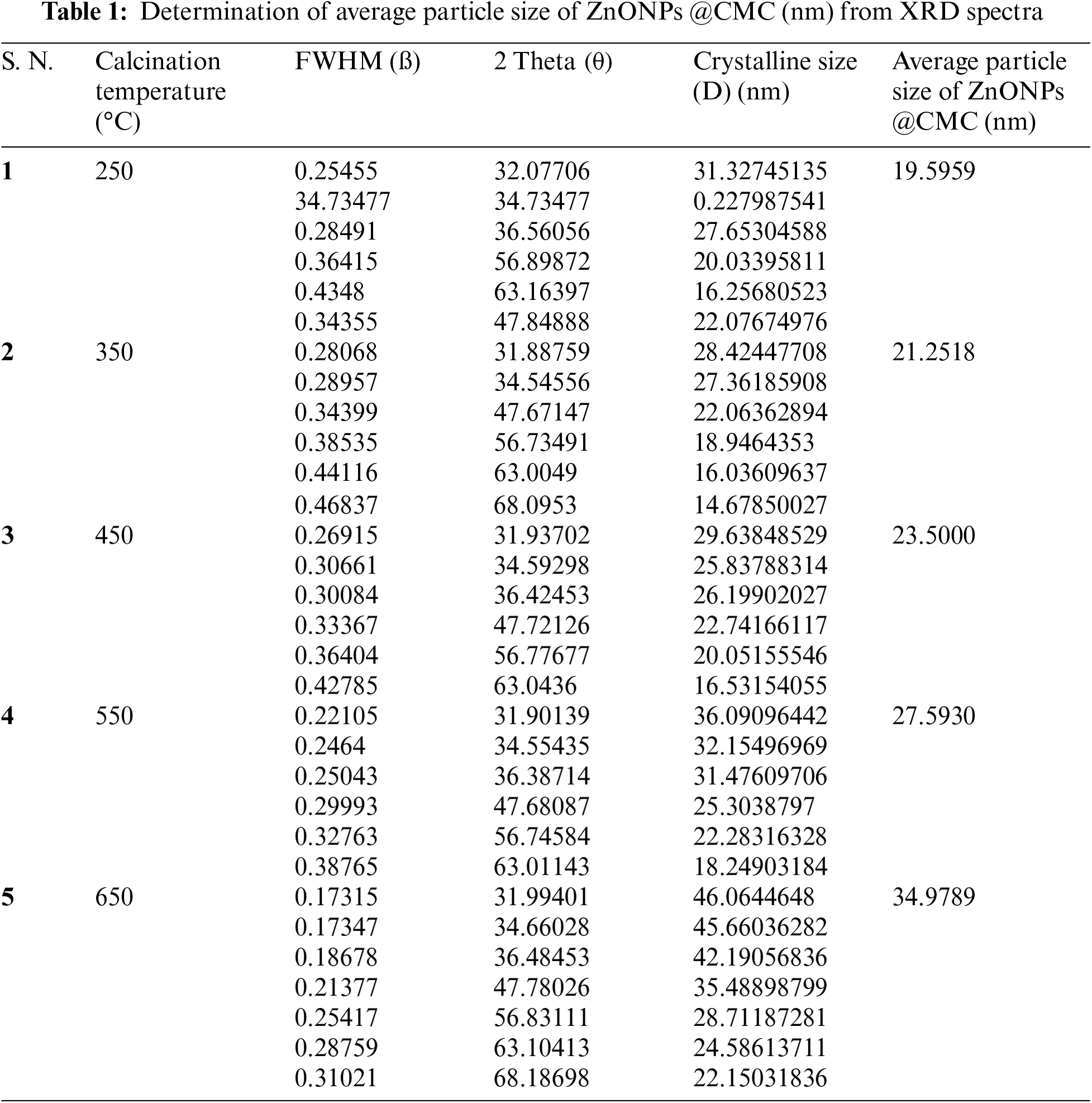
The crystallite size of ZnONPs @CMCcalcinated at 250°C, 350°C, 450°C, 550°C, and 650°C were 19.59, 21.25, 23.50, 27.59, and 34.97 nm, respectively. The details of values of all parameters used in the Debye-Scherrer equation are listed in Table 1. Accordingly, crystallite size rises slightly as the calcination temperature increases from 250°C to 450°C and further increase in calcination temperature increases crystallite size significantly because higher calcination temperatures can lead to particle growth and agglomeration and the process involve crystallization and sintering of the NPs, which can cause them to fuse and form larger particles [42]. Hence, increasing calcination temperature significantly affects the size of CMC-wrapped ZnONPs.
3.3 UV Vis Analysis of Photocatalytic Degradation of MB Dye
The UV-visible absorbance plot of photocatalytic degradation of MB dye by ZnO-CMC NPs at different calcination temperatures (250°C, 350°C, 450°C, 550°C, and 650°C) are depicted in Figs. 10–14. The degradation of MB dye by ZnONPs@CMC was observed for up to 3 h. The dye’s blue color faded and became colorless with time (Fig. 15), and this was confirmed by the decreasing absorbance with increasing the time duration under sunlight.
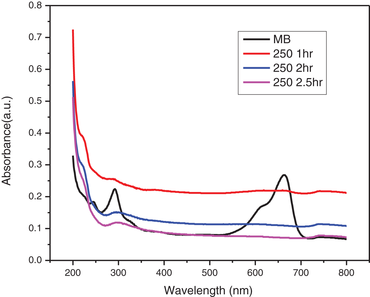
Figure 10: UV-visible absorbance plot of photocatalytic degradation of MB dye by ZnO-CMC NPs calcinated at 250°C
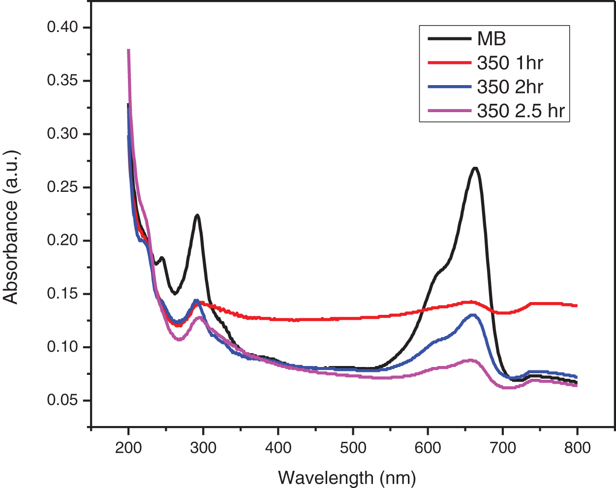
Figure 11: UV-visible absorbance plot of photocatalytic degradation of MB dye by ZnO-CMC NPs calcinated at 350°C
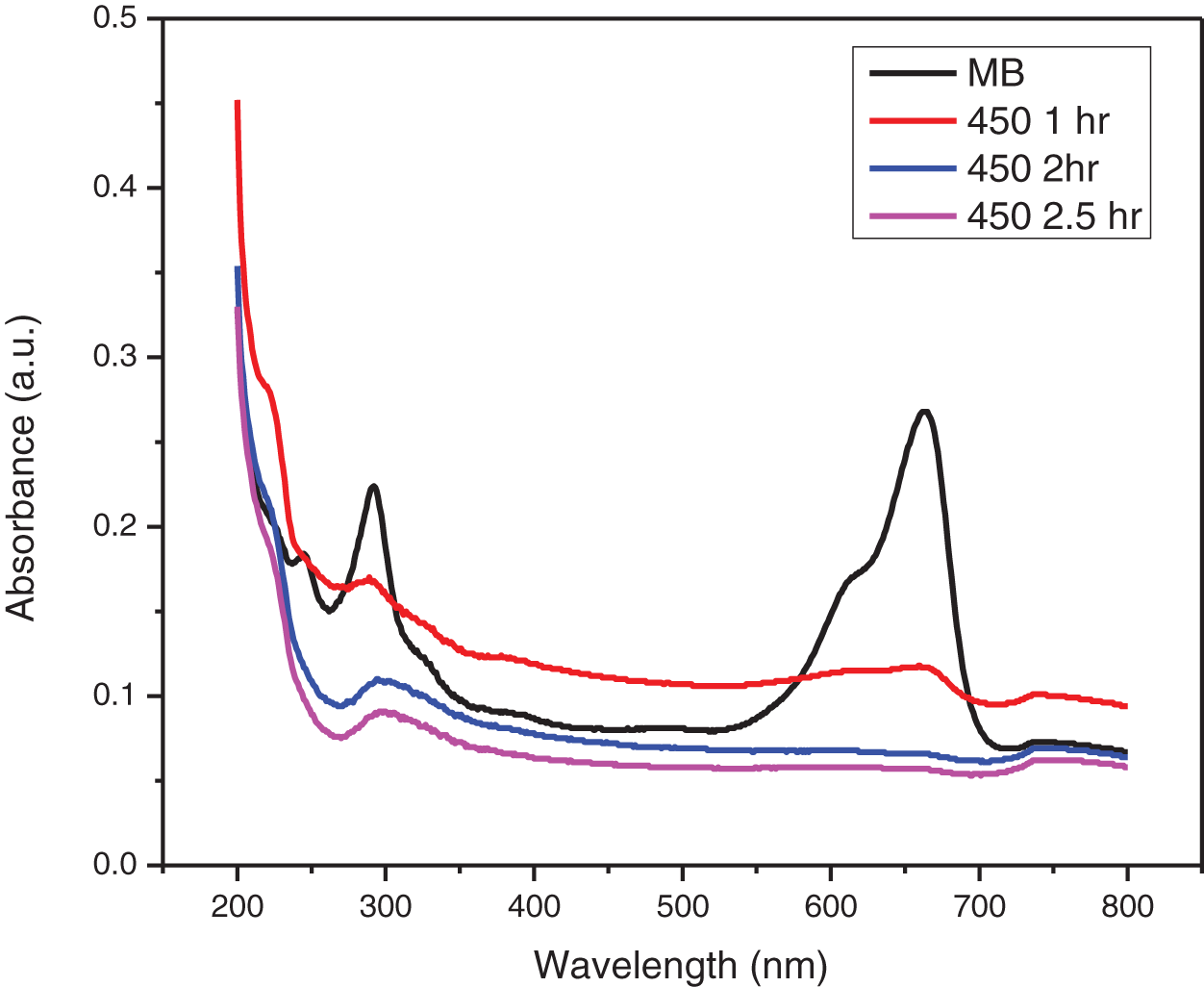
Figure 12: UV-visible absorbance plot of photocatalytic degradation of MB dye by ZnO-CMC NPs calcinated at 450°C

Figure 13: UV-visible absorbance plot of photocatalytic degradation of MB dye by ZnO-CMC NPs calcinated at 550°C
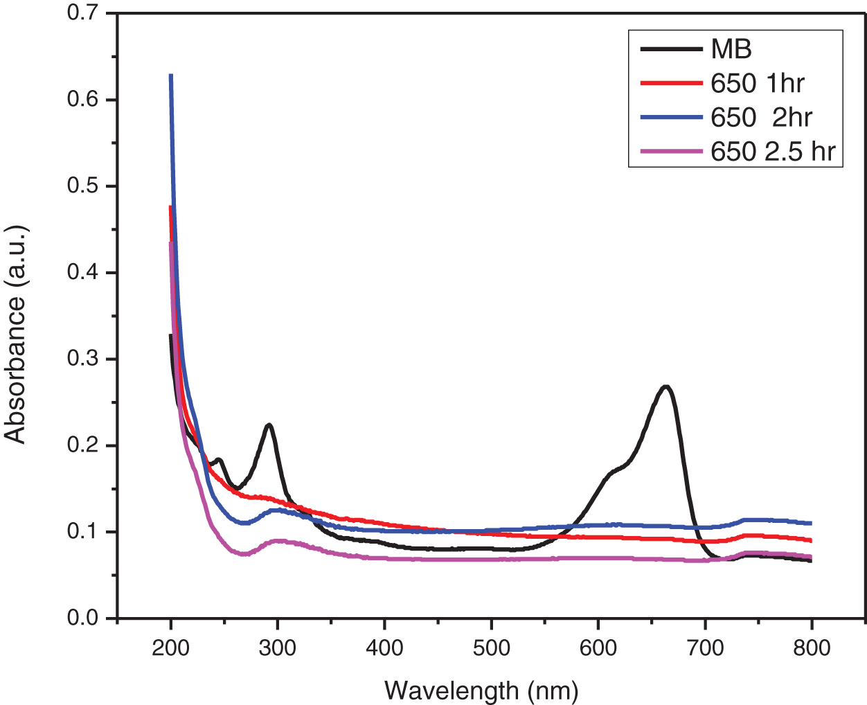
Figure 14: UV-visible absorbance plot of photocatalytic degradation of MB dye by ZnO-CMC NPs calcinated at 650°C

Figure 15: Photocatalytic degradation of MB dye by various ZnONPs@CMC samples calcinated at different temperatures
The UV-visible absorption spectra of MB dyes have the strongest absorption peak at about 664 nm due to MB monomer. An MB dimer is responsible for the shoulder peak, which is located at roughly 612 nm. Two more bands with maxima at 292 and 245 nm (linked to substituted benzene rings) emerge in the ultraviolet area. The absorbance peak’s strength steadily drops over time as the photocatalytic degradation occurs. The decrease in absorbance signifies that the number of MB dye molecules in the solution is diminishing due to its degradation. The change in the absorbance peak’s location and a drop in absorbance intensity are also observed. This shift is towards blueshift (shorter wavelengths) or redshift (longer wavelengths). As the MB dye molecules decompose, their chemical structures alter, causing the shift. The smaller fragments created during the degradation process or intermediate degradation products can correlate to these new peaks identified. This observation is consistent with the earlier study on MB that was conducted [34].
3.4 Mechanism of Photocatalytic Degradation
Electrostatic interactions draw the positively charged MB dye molecules to the negatively charged CMC layer on the ZnO NPs. The dye molecules are adsorbed onto their surface to prepare the nanoparticles for photocatalytic degradation. Electrons in the ZnO NPs’ valence band are promoted to move to the conduction band when exposed to UV light by absorbing the light’s energy by the CMC around the NPs. Pairs of electrons are produced. ZnO’s conduction band’s excited electrons react with nearby oxygen molecules (O2) to produce reactive oxygen species (ROS), including hydroxyl radicals (OH-) and superoxide radicals (O2-). Strongly reactive, these ROS can cause organic substances, such as the MB dye, to degrade. The produced reactive oxygen species (ROS) interact with the adsorbed MB dye molecules on the ZnO NPs wrapped in CMC. Dyes eventually deteriorate due to the ROS’s oxidation of the dye molecules and subsequent disintegration into simpler, less complicated molecules. The MB dye’s broken-down products are released into the surrounding solution from the surface of the CMC-wrapped ZnO NPs as the photocatalytic degradation process proceeds. The stepwise representation of the possible mechanism is given below and shown in Fig. 16.
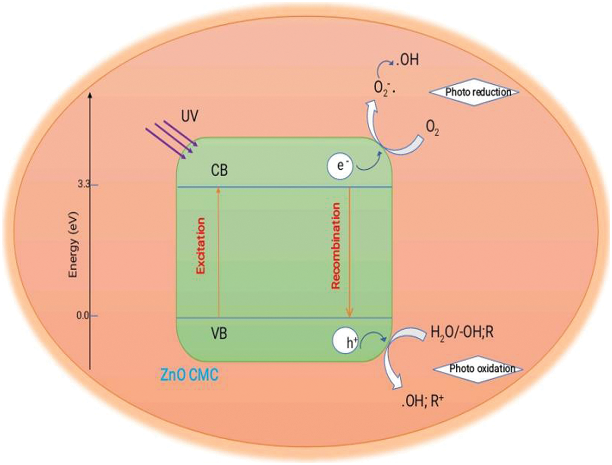
Figure 16: Mechanism of photocatalytic degradation of MB dye by ZnO-CMC NPs under sunlight
Step 1: Absorption of photons
ZnO NPs absorb photons from a light source, typically UV light, leading to the generation of electron-hole pairs (e−/h+)
Step 2: Generation of reactive oxygen species (ROS)
The excited electrons (e−) in ZnO-NPs transfer to molecular oxygen (O2), generating superoxide radicals (O2•−).
Step 3: Reaction with water
Superoxide radicals (O2•−) react with water (H2O) to form hydroperoxyl radicals (HO2•−).
Step 4: Degradation of MB dye
The hydroperoxyl radicals (HO2•−) generated in the previous step attack the methylene blue dye (MB) molecules, leading to their degradation.
Overall equation:
Degradation products are shown in Fig. 16.
This study presents the successful synthesis of CMC-wrapped ZnO NPs using zinc acetate dihydrate and sodium hydroxide, with CMC as a capping agent at different calcination temperatures. The formation of ZnO nanoparticles is confirmed by FTIR, UV-vis, and XRD characterization techniques. The calcination temperature significantly impacts the crystallite size, which increases from 19.59 to 34.97 nm as the calcination temperature rises from 250°C to 650°C. Higher calcination temperatures result in better degradation efficiency from UV-vis spectra of the MB degradation process. The photocatalytic degradation of MB dye under sunlight showed that ZnONPs@CMC is an efficient photo nanocatalyst that can be used in dye-contaminated wastewater treatment for environmental cleanup and, hence, is helpful in water pollution control.
Acknowledgement: We are thankfully acknowledged to the Department of Chemistry, Institute of Science, Banaras Hindu University, India, for XRD analysis of nanoparticle samples and the Department of Chemistry, Guru Ghasidas Vishwavidyalaya, for FTIR analysis and other facilities.
Funding Statement: This research was funded by UGC New Delhi/MRP Project No. 42-387/2013 (SR).
Author Contributions: Abhishek Kumar Patel: Conceptualization, Methodology, Data Collection, Writing—Original Draft. Ashlesha P. Kawale: Data Analysis, Software, Writing—Review & Editing. Neeru Sharma: Software, Validation, Visualization. Nishant Shekhar: Data Analysis, Editing. Arti Srivastava: Review & Editing, Supervision. Subhash Banerjee: Review & Editing, Supervision. All authors reviewed the results and approved the final version of the manuscript.
Availability of Data and Materials: The datasets generated during and/or analyzed during the current study are available from the corresponding author on reasonable request.
Ethics Approval: Not applicable.
Conflicts of Interest: The authors declare that they have no conflicts of interest to report regarding the present study.
References
1. Altammar KA. A review on nanoparticles: characteristics, synthesis, applications, and challenges. Front Microbiol. 2023;14:1155622. [Google Scholar] [PubMed]
2. Gelperina S, Kisich K, Iseman MD, Heifets L. The potential advantages of nanoparticle drug delivery systems in chemotherapy of tuberculosis. Am J Respir Crit Care Med. 2005;172(12):1487–90. doi:10.1164/rccm.200504-613PP. [Google Scholar] [PubMed] [CrossRef]
3. Tan HW, An J, Chua CK, Tran T. Metallic nanoparticle inks for 3D printing of electronics. Adv Electron Mater. 2019;5(5):1800831. doi:10.1002/aelm.201800831. [Google Scholar] [CrossRef]
4. Das PK, Mohanty C, Purohit GK, Mishra S, Palo S. Nanoparticle assisted environmental remediation: applications, toxicological implications and recommendations for a sustainable environment. Environ Nanotechnol, Monit Manage. 2022;1:100679. doi:10.1016/j.enmm.2022.100679. [Google Scholar] [CrossRef]
5. Ghule K, Ghule AV, Chen BJ, Ling YC. Preparation and characterization of ZnO nanoparticles coated paper and its antibacterial activity study. Green Chem. 2006;8(12):1034–41. doi:10.1039/B605623G. [Google Scholar] [CrossRef]
6. Rasmussen JW, Martinez E, Louka P, Wingett DG. Zinc oxide nanoparticles for selective destruction of tumor cells and potential for drug delivery applications. Expert Opin Drug Deliv. 2010;7(9):1063–77. doi:10.1517/17425247.2010.502560. [Google Scholar] [PubMed] [CrossRef]
7. Roy A, Sharma A, Yadav S, Jule LT, Krishnaraj R. Nanomaterials for remediation of environmental pollutants. Bioinorg Chem Appl, 2021;2021(1):1–17. doi:10.1155/2021/1764647. [Google Scholar] [PubMed] [CrossRef]
8. Cheng N, Tian J, Liu Q, Ge C, Qusti AH, Asiri AM, et al. Au-nanoparticle-loaded graphitic carbon nitride nanosheets: green photocatalytic synthesis and application toward the degradation of organic pollutants. ACS Appl Mat Interfaces. 2013;5(15):6815–9. doi:10.1021/am401802r. [Google Scholar] [PubMed] [CrossRef]
9. Bindhu MR, Saranya P, Sheeba M, Vijilvani C, Rejiniemon TS, Al-Mohaimeed, et al. Functionalization of gold nanoparticles by β-cyclodextrin as a probe for the detection of heavy metals in water and photocatalytic degradation of textile dye. Environ Res. 2021;201:111628. doi:10.1016/j.envres.2021.111628. [Google Scholar] [PubMed] [CrossRef]
10. Zhang Z, Chen D. Consideration of Orowan strengthening effect in particulate-reinforced metal matrix nanocomposites: a model for predicting their yield strength. Scr Mater. 2006;54(7):1321–6. doi:10.1016/j.scriptamat.2005.12.017. [Google Scholar] [CrossRef]
11. Wang H, Liang Y, Gong M, Li Y, Chang W, Mefford T, et al. An ultrafast nickel-iron battery from strongly coupled inorganic nanoparticle/nanocarbon hybrid materials. Nat Commun. 2012;3(1):917. doi:10.1038/ncomms1921. [Google Scholar] [PubMed] [CrossRef]
12. Liu T, Wang Z, Wang X, Yang G, Liu Y. Adsorption-photocatalysis performance of polyaniline/dicarboxyl acid cellulose@graphene oxide for dye removal. Int J Biol Macromol. 2021;182:492–501. doi:10.1016/j.ijbiomac.2021.04.038. [Google Scholar] [PubMed] [CrossRef]
13. Chen Y, Xiang Z, Wang D, Kang J, Qi H. Effective photocatalytic degradation and physical adsorption of methylene blue using cellulose/GO/TiO2 hydrogels. RSC Adv. 2020;10(40):23936–43. doi:10.1039/d0ra04509h. [Google Scholar] [PubMed] [CrossRef]
14. Meneses IP, Novaes SD, Dezotti RS, Oliveira PV, Petri DFS. CTAB-modified carboxymethyl cellulose/bagasse cryogels for the efficient removal of bisphenol A, methylene blue and Cr(VI) ions: batch and column adsorption studies. J Hazard Mater. 2022;421:126804. doi:10.1016/j.jhazmat.2021.126804. [Google Scholar] [PubMed] [CrossRef]
15. Qasem KMA, Khan S, Chinnam S, Saleh HAM, Mantasha I, Zeeshan M, et al. Sustainable fabrication of Co-MOF@CNT nano-composite for efficient adsorption and removal of organic dyes and selective sensing of Cr(VI) in aqueous phase. Mater Chem Phys. 2022;291:126748. doi:10.1016/j.matchemphys.2022.126748. [Google Scholar] [CrossRef]
16. Jawad AH, Saber SEM, Abdulhameed AS, Reghioua A, Othman ZAAL, Wilson LD. Mesoporous activated carbon from mangosteen (Garcinia mangostana) peels by H3PO4 assisted microwave: optimization, characterization, and adsorption mechanism for methylene blue dye removal. Diam Relat Mater. 2022;129:109389. doi:10.1016/j.diamond.2022.109389. [Google Scholar] [CrossRef]
17. Sharma D, Rajput J, Kaith BS, Kaur M, Sharma S. Synthesis of ZnO nanoparticles and study of their antibacterial and antifungal properties. Thin Solid Films. 2010;519(3):1224–9. doi:10.1016/j.tsf.2010.08.073. [Google Scholar] [CrossRef]
18. Osmond MJ, Mccall MJ. Zinc oxide nanoparticles in modern sunscreens: an analysis of potential exposure and hazard. Nanotoxicology. 2010;4(1):15–41. doi:10.3109/17435390903502028. [Google Scholar] [PubMed] [CrossRef]
19. Ha NH, Thinh DD, Huong NT, Phuong NH, Thach PD, Hong HS. Fast response of carbon monoxide gas sensors using a highly porous network of ZnO nanoparticles decorated on 3D reduced graphene oxide. Appl Surface Sci. 2018;434:1048–54. doi:10.1016/j.apsusc.2017.11.047. [Google Scholar] [CrossRef]
20. Strunk J, Kähler K, Xia X, Muhler M. The surface chemistry of ZnO nanoparticles applied as heterogeneous catalysts in methanol synthesis. Surf Sci. 2009;603(10–12):1776–83. doi:10.1016/j.susc.2008.09.063. [Google Scholar] [CrossRef]
21. Uthirakumar P, Kim HG, Hong CH. Zinc oxide nanostructures derived from a simple solution method for solar cells and LEDs. Chem Eng J. 2009;155(3):910–5. doi:10.1016/j.cej.2009.09.025. [Google Scholar] [CrossRef]
22. Pradeeswari K, Venkatesan A, Pandi P, Karthik K, Krishna KH, Kumar RM. Study on the electrochemical performance of ZnO nanoparticles synthesized via non-aqueous sol-gel route for supercapacitor applications. Mater Res Express. 2019;6(10):105525. doi:10.1088/2053-1591/ab3cae. [Google Scholar] [CrossRef]
23. Bisht G, Rayamajhi S. ZnO nanoparticles: a promising anticancer agent. Nanobiomedicine. 2016;3:9. doi:10.5772/63437. [Google Scholar] [PubMed] [CrossRef]
24. Singh A, Gautam PK, Verma A, Singh V, Shivapriya PM, Shivalkar S, et al. Green synthesis of metallic nanoparticles as effective alternatives to treat antibiotics resistant bacterial infections: a review. Biotechnology Reports. 2020;25:e00427. doi:10.1016/j.btre.2020.e00427. [Google Scholar] [PubMed] [CrossRef]
25. Ghanbarzadeh B, Almasi H. Physical properties of edible emulsified films based on carboxymethyl cellulose and oleic acid. Int J Biol Macromol. 2011;48(1):44–9. doi:10.1016/j.ijbiomac.2010.09.014. [Google Scholar] [PubMed] [CrossRef]
26. Alam K, Ahmed M, Akter S, Islam N, Eun JB. Effect of carboxymethylcellulose and starch as thickening agents on the quality of tomato ketchup. Pak J Nutr. 2009;8(8):1144–9. [Google Scholar]
27. Cai Z, Wu J, Du B, Zhang H. Impact of distribution of carboxymethyl substituents in the stabilizer of carboxymethyl cellulose on the stability of acidified milk drinks. Food Hydrocoll. 2018;76:150–7. doi:10.1016/j.foodhyd.2016.12.034. [Google Scholar] [CrossRef]
28. Butun S, Ince FG, Erdugan H, Sahiner N. One-step fabrication of biocompatible carboxymethyl cellulose polymeric particles for drug delivery systems. Carbohydrate Polym. 2021;86(2):636–43. doi:10.1016/j.carbpol.2011.05.001. [Google Scholar] [CrossRef]
29. Zennifer A, Senthilvelan P, Sethuraman S, Sundaramurth D. Key advances of carboxymethyl cellulose in tissue engineering & 3D bioprinting applications. Carbohydr Polym. 2021;256:117561. doi:10.1016/j.carbpol.2020.117561. [Google Scholar] [PubMed] [CrossRef]
30. He F, Zhao D, Liu J, Roberts CB. Stabilization of Fe−Pd nanoparticles with sodium carboxymethyl cellulose for enhanced transport and dechlorination of trichloroethylene in soil and groundwater. Ind Eng Chem Res. 2007;46(1):29–34. doi:10.1021/ie0610896. [Google Scholar] [CrossRef]
31. Yan H, Zhang W, Kan X, Dong L, Jiang Z, Li H, et al. Sorption of methylene blue by carboxymethyl cellulose and reuse process in a secondary sorption. Colloid Surf A: Physicochem Eng Aspects. 2011;380(1–3):143–51. doi:10.1016/j.colsurfa.2011.02.045. [Google Scholar] [CrossRef]
32. Qin L, Shing C, Sawyer S, Dutta PS. Enhanced ultraviolet sensitivity of zinc oxide nanoparticle photoconductors by surface passivation. Opt Mater. 2011;33(2):359–62. doi:10.1016/j.optmat.2010.09.020. [Google Scholar] [CrossRef]
33. Houas A, Lachheb H, Ksibi M, Elaloui E, Guillard C, Herrmann J-M. Photocatalytic degradation pathway of methylene blue in water. Appl Catal B: Environ. 2001;31(2):145–57. doi:10.1016/S0926-3373(00)00276-9. [Google Scholar] [CrossRef]
34. Khan I, Saeed K, Zekker I, Zhang B, Hendi AH, Ahmad A, et al. Review on methylene blue: its properties, uses, toxicity and photodegradation. Water. 2022;14(2):242. doi:10.3390/w14020242. [Google Scholar] [CrossRef]
35. Alwan RM, Kadhim QA, Sahan KM, Ali RA, Mahdi RJ, Kassim NA, et al. Synthesis of zinc oxide nanoparticles via sol-gel route and their characterization. Nanosci Nanotechnol. 2015;5(1):1–6. doi:10.5923/j.nn.20150501.01. [Google Scholar] [CrossRef]
36. RaoufiD. Synthesis and microstructural properties of ZnO nanoparticles prepared by precipitation method. Renew Energy. 2013;50:932–7. doi:10.1016/j.renene.2012.08.076. [Google Scholar] [CrossRef]
37. Madathil ANP, Vanaja KA, Jayaraj MK. Synthesis of ZnO nanoparticles by hydrothermal method. In: Nanophotonic materials IV; 2007. vol. 6639, p. 47–55. doi:10.1117/12.730364. [Google Scholar] [CrossRef]
38. Hasanpoor M, Aliofkhazraei M, Delavari HJPMS. Microwave-assisted synthesis of zinc oxide nanoparticles. Procedia Mater Sci. 2015;11:320–5. doi:10.1016/j.mspro.2015.11.101. [Google Scholar] [CrossRef]
39. Bai X, Li L, Liu H, Tan L, Liu T, Meng X. Solvothermal synthesis of ZnO nanoparticles andanti-infection application in vivo. ACS Appl Mat Interfaces. 2015;7(2):1308–17. doi:10.1021/am507532p. [Google Scholar] [PubMed] [CrossRef]
40. Anand V, Srivastava VC. Zinc oxide nanoparticles synthesis by electrochemical method: optimization of parameters for maximization of productivity and characterization. J Alloys Comp. 2015;636:288–92. doi:10.1016/j.jallcom.2015.02.189. [Google Scholar] [CrossRef]
41. Safeera TA, Anila EI. Synthesis and characterization of ZnO nanophosphor by microwave combustion technique. Int J Recent Innov Eng Res. 2017;2:21–5. [Google Scholar]
42. Kayani ZN, Saleemi F, Batool I. Effect of calcination temperature on the properties of ZnO nanoparticles. Appl Phys A Mater Sci Process. 2015;12(2):75–80. doi:10.1007/s00339-015-9019-1. [Google Scholar] [CrossRef]
43. Xiong G, Pal U, Serrano JG, Ucer KB, Williams RT. Photoluminesence and FTIR study of ZnO nanoparticles: the impurity and defect perspective. Physica Status Solidi C. 2006;3(10):3577–81. doi:10.1002/pssc.200672164. [Google Scholar] [CrossRef]
44. Kołodziejczak-Radzimska A, Markiewicz E, Jesionowski T. Structural characterization of ZnO particles obtained by the emulsion precipitation method. J Nanomat. 2012;2012:15–5. doi:10.1155/2012/656353. [Google Scholar] [CrossRef]
45. Ibrahim NA, Nada AA, Hassabo AG, Eid BM, Noor El-Deen AM, Abou-Zeid NY. Effect of different capping agents on physicochemical and antimicrobial properties of ZnO nanoparticles. Chem Pap. 2017;71:1365–75. doi:10.1007/s11696-017-0132-9. [Google Scholar] [CrossRef]
Cite This Article
 Copyright © 2024 The Author(s). Published by Tech Science Press.
This work is licensed under a Creative Commons Attribution 4.0 International License , which permits unrestricted use, distribution, and reproduction in any medium, provided the original work is properly cited.
 Downloads
 Citation Tools