 Open Access
ARTICLE
Mathematical Modelling and Simulations of Active Direct Methanol Fuel Cell
a
Department of Chemical Engineering, Jadavpur University, Kolkata, West Bengal, India.
b
Department of Chemical Engineering, Indira Gandhi Institute of Technology, Sarang,
Dhenkanal, Odisha, India.
* Corresponding Author: e-mail:
Journal of Polymer Materials 2023, 40(3-4), 125-139. https://doi.org/10.32381/JPM.2023.40.3-4.1
Abstract
A one dimensional isothermal model is proposed by modelling the kinetics of methanol transport at anode flow channel (AFC), membrane and cathode catalyst layer of direct methanol fuel cell (DMFC). Analytical model is proposed to predict methanol cross-over rate through the electrolyte membrane and cell performance. The model presented in this paper considered methanol diffusion and electrochemical oxidation at the anode and cathode channels. The analytical solution of the proposed model was simulated in a MATLAB environment to obtain the polarization curve and leakage current. The effect of methanol concentration on cell voltage and leakage current is studied. The methanol cross-over has the significant impact on cell performance. The presented model predicts higher leakage current with the increase of methanol feed concentration. The cell performance was predicted at 70°C and various methanol feed concentration. The proposed model was validated with the experimental polarization curve of active DMFC.Keywords
Fuel cell is considered to be a potential candidate for portable and stationary applications. It becomes widely popular due to its higher fuel conversion efficiency, low pollutant emissions and high power density[1]. In near future, it has the potential to replace internal combustion (IC) engine in vehicles. The development of high performance fuel cell is crucial to replace IC engine. A significant amount of work has been done in recent years to develop a high energy conversion efficient fuel cells with higher power density to replace IC engines. The direct methanol fuel cell is considered to be a potential candidate to replace conventional IC engine in vehicles[2, 3]. It produces electricity by electrochemical oxidation of methanol at anode and has higher fuel conversion efficiency. Moreover, the higher energy density of fuel and its low temperature operation favours potential applications in vehicles[4]. The schematic representation of a typical DMFC is shown in fig. 1. The DMFC is categorized in to two types i.e. active and passive DMFC based on the modes of fuel supply to the AFC[5]. In active DMFC, liquid fuel is supplied whereas in case of passive DMFC, vapour fuel is supplied. The benefit of passive DMFC is that it is designed at low cost and deliver high power density. However, it is more convenient to control the fuel cell parameters like methanol concentration and its flow rate, temperature, etc. in active DMFC[6].
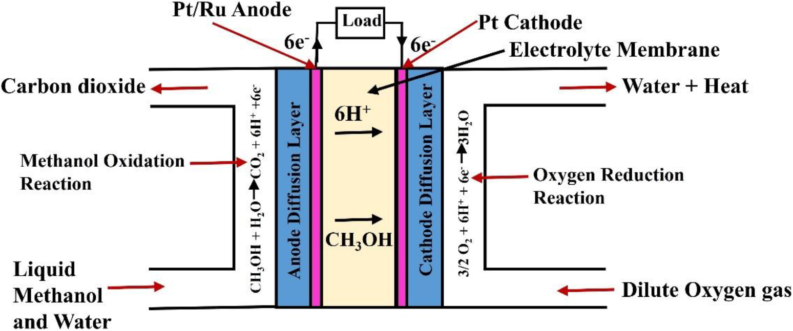
Fig. 1: Schematic representation of a DMFC
The major concern of active DMFC is fuel cross-over which resulted higher fuel loss and generating leakage current. The leakage current was produced at cathode due to the oxidation of methanol. The oxidation of methanol at cathode flow channel produces water which affects cell performance[7-10]. The lack of water management at cathode resulted flooding of baking and catalyst layer thereby reducing cell performance. The cell voltage and fuel conversion efficiency was drastically reduced due to fuel cross-over. Another factor which affects the fuel cell performance is slow kinetics of electrochemical reaction at anode[11]. Meyers and Newman et al.,[12] proposed the electrochemical oxidation of methanol in three steps as given below.
The several model has been proposed to investigate the effect of methanol cross-over flux on cell performance. The analytical model of the DMFC is considered to be more effective due its following features like easy to implement, low computational cost and most suited for the parametric and optimization purpose[13]. There are several numerical model was proposed by the investigators for active and passive DMFC[10-13]. The effect of electro-osmotic drag during the transport of methanol through the membrane is studied by Ren et al.,[14]. They assumed that the diluted water molecules dragged methanol through the membrane and diffusion was controlled by convection effect. The effect of cell temperature on methanol cross-over was analysed by Narayan et al.,[15]. In their study, they confirmed that the rate of fuel cross-over increases with the temperature. They also studied the effect of membrane thickness on methanol cross-over flux. They confirmed that the rate of methanol cross-over reduces with the increase of membrane thickness. The rate of methanol transport was controlled by diffusion. The effect of methanol feed concentration on cell performance was investigated by Ravikumar and Shukla[16]. They found that the cell performance was affected by methanol feed concentration and significant impact was observed at more than 2M methanol feed. The effect of mixed potential on cell performance was studied by Wang et al., In their study, they analysed the methanol oxidation along with oxygen reduction at cathode. They found that the permeated methanol is completely oxidized at cathode layer to form carbon dioxide. The oxidation of methanol at cathode produces leakage current which reduces cell performance.
The different mathematical model was developed to study the effect of methanol feed concentration and leakage current on cell performance. Baxter et al., has developed a 1D mathematical model of anode catalyst layer[17]. In their study, they assumed that the oxidation of methanol is on liquid phase. Moreover, they assumed that the CO2 gas produced by oxidation reaction has higher solubility to water. Hence, they considered CO2 as a liquid phase in their mathematical model. However, they ignored the methanol oxidation at cathode layer. Scott et al. has developed a simplistic 1D liquid phase mathematical model of anode flow channel with methanol oxidation at cathode[18]. They found that the slow kinetic of methanol oxidation limits cell performance. The effect of methanol cross-over on cell performance was investigated by Garcia et al., In their study, they included the electrochemical oxidation of methanol at cathode and predicted leakage current.
In this work, the kinetics of methanol transport at anode flow channel (AFC), membrane and cathode catalyst layer is considered to develop a theoretical model. The model considers the kinetics of methanol diffusion and its electrochemical oxidation at AFC and cathode catalyst layer. The effect of methanol concentration on the fuel cell performance is studied. Moreover, the effect of methanol feed concentration on the generation of leakage current is also predicted. The proposed model is validated with the experimental polarization results.
The experimental studies was performed in a fabricated membrane electrode assembly (MEA) which is reported in our earlier work[4, 19, 22]. The test membrane (5cm×5cm) was fixed between the catalyst layer and test was conducted for different methanol feed concentrations. We have used chitosan based hybrid membrane as a test membrane for experimental studies. The main ingredients of the hybrid membrane are chitosan, polyvinyl alcohol, hygroscopic zirconia and ionic liquid. The fabrication procedure and the properties of test membrane was reported in our earlier work[19, 22]. MEA was fabricated by assembling the anode and cathode catalyst. The catalyst layer was prepared by thermal pressing of catalyst power on carbon cloth. The anode catalyst was prepared by thermally pasting the Pt/Ru catalyst powder on carbon cloth @4mg/cm2. The cathode catalyst was prepared by thermally pasting the Platinum catalyst powder on carbon cloth @2mg/cm2. The DMFC stack was prepared by assembling the MEA. The MEA was assembled between two graphite plates and feed flow channel was introduced. The liquid methanol and dilute oxygen gas is supplied to the anode and cathode side of DMFC. The flow rate of methanol and dilute oxygen gas was controlled by Rotameter. The liquid methanol is supplied to the anode side of cell at a flow rate of 1ml/min. The dilute oxygen flow rate is maintained at 100ml/min. During the test, cell temperature was maintained at 70°C. The cell potential was recorded by externally connected EIS workstation.
The simulated environment was developed by modelling the methanol flow on AFC and membrane. During modelling, oxidation reaction of methanol at anode and cathode flow channel is also considered. The polarization curve obtained from the simulation environment is compared with the experimental results.
A theoretical model of DMFC is developed by considering the diffusion kinetics of methanol at anode and cathode flow channel. The electrochemical reaction of methanol and dilute oxygen gas at AFC and cathode catalyst layer is considered. During modelling, following assumptions are considered for developing simulation environment.
1. All components transported in AFC, membrane and cathode flow channel are considered to be in single phase (liquid phase). During electrochemical oxidation of methanol, carbon dioxide vapour is produced which is also considered to be a liquid state. We are assuming that the solubility of CO2 vapour in water is very high and will remains in liquid phase.
2. The electrochemical oxidation of methanol in anode flow channel and cathode obeys Tafel kinetic.
3. Temperature remains constant throughout the electrochemical reaction.
4. Proton conductivity through the membrane remains constant.
5. The anode catalyst layer is considered to be homogeneous porous electrode and the reaction in catalyst layer is assumed to be homogeneous.
6. Methanol diffusivity through the membrane remains constant.
7. One dimensional approach of the cell including anode flow channel, membrane and cathode flow channel.
8. Liquid is flowing in one direction i.e. plug flow and there is no back mixing.
The electrochemical reaction between fuel (methanol) and O2 gas produces heat and electrical energy in DMFC. The electrical energy produced in a single cell of DMFC is called open circuit voltage, Voc. The electrochemical reaction of DMFC is represented in Fig. 1. In DMFC, loss of voltage is occurred due to polarization loss. The polarization loss is categorized in to three type i.e. active, ohmic and concentration polarization loss. In most cases, ohmic loss was dominated over the other and it has significant effect on cell voltage. The cell voltage (Vcell) is defined as the net amount of electrical energy produced in a DMFC. The theoretical cell voltage (Vcell) of the cell is predicted by using following the expression[11].
Here, Vcell is the cell voltage in volt, UU2 and UMeOH are the potential of oxygen reduction and ethanol oxidation respectively, ηA and ηC are the anode and cathode over potentials respectively. The last term in the expression represents ohmic drop across the membrane.
The simplified one dimensional approach of anode flow channel (AFC) in DMFC is represented in fig. 2. The anode flow channel is modelled to predict the methanol cross-over rate through the membrane and anode overpotential. The concentration distribution and flow direction of methanol in AFC is shown in the fig. The model considered the AFC in to three partition layer i.e. anode diffusion layer (ADL), anode catalyst layer (ACL) and membrane. The methanol concentration and thickness of each partition layer is represented.The liquid methanol is transported in X- direction and the boundary conditions for each partition layer is given below:
ADL: Thickness (Ib); At X=0: c=cb; At X=X1: c=
ACL: Thickness (Ia); At X=XI: c=aI; At X=XII: c=
Membrane: Thickness (Im); At X=
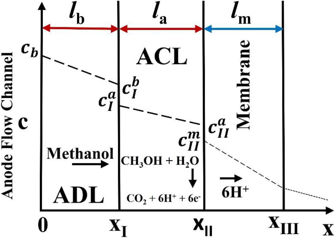
Fig. 2: A simplistic one dimensional approach of anode flow channel in a DMFC
The kinetics of methanol transport in AFC is modelled to propose methanol cross-over rate and anode side over-potential. The methanol transport in ADL is assumed to be controlled by first order fickian diffusion. The methanol molar flux through the ADL is expressed by fickian diffusion law. The diffusion of methanol in ADL is expressed by first order fickian law as given below:
Here, NMeOH,X is the methanol molar flux in ADL (mol./cm2.s), cMeOH, is the concentration of methanol in ADL and is the diffusivity of methanol in the ADL (cm2/s.).
The molar flux of methanol transported through the membrane is assumed to be controlled by the combined effect of diffusion and electro-osmotic drag.
The equation (6) is solved by using boundary conditions at membrane interface. The boundary conditions at membrane interface is mentioned earlier. The above equation was m analytically solved by considering the boundary conditions at interfaces. The equation was solved to get the general expression of methanol molar flux through the membrane. The general expression of methanol molar flux through the membrane was proposed by A.A. Kulikovsky[20]. The expression of methanol molar flux proposed by A.A. Kulikovsky was modified as per the boundary conditions presented in our model which is schematically shown in Fig. 2. The general expression for predicting the methanol molar flux though the membrane is given below:
Here,
Here,
A.A. Kulikovsky numerically solved the kinetics of methanol diffusion and electrochemical reaction of fuel cell and proposed a theoretical model to predict the anode side over-potential[20]. The kinetic of methanol oxidation and oxygen reduction at AFC and cathode catalyst layer is considered. The model equation proposed for predicting the anode over-potential (ηA) is given below
Here,
The equation (8) is used to predict the anode side over-potential.
The oxygen reduction reaction was occurred in the catalyst layer. The oxygen reduction reaction is shown in Fig. 1. The reduction reaction produces water in the cathode diffusion layer. The permeated methanol is also oxidized in the catalyst layer leaving out electric current (leakage current) and heat. Garcia et al.,[11] proposed a theoretical model to relate leakage current with cathode over-potential. In their model, kinetics of oxygen reduction was considered. The kinetics of oxygen reduction reaction was modelled. The proposed theoretical model is given below:
Here, Ileak is the leakage current generated by oxidation of methanol at cathode (A/cm2), is the charge transfer at cathode interface and is the cathode side over potential in volt.
The leakage current is also related with the methanol cross-over flux through the membrane. The expression of leakage current is given below:
The equation (9) is further simplified to get the expression of cathode over potential (ηc). The general expression for calculating cathode over potential is
Here, j=ICell, I=Ileak,
The expression of anode and cathode side over-potential is substituted in equation (4) to predict cell voltage. The simplified I-D model of active DMFC was developed to predict the cell voltage at different current density. The proposed model of active DMFC was simultaneously solved at different current density to predict polarization curve. The model equations were solved in MATLAB workspace for different methanol feed concentration. The model parameter used for predicting the polarization curve is given in Table 1. The leakage current of the DMFC was predicted by using the equation (10). For predicting leakage current, methanol molar flux was calculated from equation (7). The leakage current was calculated at different methanol feed concentrations. The model equations was simultaneously solved in a MATLAB environment at different current density and predicts the leakage current.
The effect of methanol concentrations on leakage current of an active DMFC is shown in Fig. 3. The leakage current gradually increases with the increase of methanol molar feed at ADL. With the increase of methanol feed concentration at anode side, more amount of methanol is crossing the membrane from anode to cathode side and taking part for methanol oxidation reaction. The maximum leakage current was observed for 2M methanol feed supply at anode side. The leakage current produces has no useful work in the cell. Hence, leakage current should be minimized to enhance cell performance. The increase of methanol molar feed concentration on anode side increases methanol cross-over and generating more leakage current. The similar type of results was predicted by Wang et al.,[8] and Garcia et al.,[11] in their study. It was also observed that the leakage current was decreases at higher current density. Therefore, it is suggested that DMFC should be operated at lower methanol feed concentration and higher current density to minimize leakage current. The effect of methanol molar flux through the membrane was predicted and shown in Fig. 4. The increase of methanol feed concentration on feed side of DMFC increases methanol cross-over rate. It was believed that the poor electrochemical oxidation kinetics of methanol at anode side causes higher methanol cross-over rate. The catalytic activity of Platinum/Ruthenium catalyst towards the oxidation of methanol was slow. Due to slow kinetics, less amount of methanol was oxidized and rest were transported through the membrane via diffusion. Hence, higher methanol cross-over rate was observed when highly concentrated methanol was fed to the anode flow channel. For better performance and improve fuel efficiency, methanol cross-over rate through the membrane should be reduced. Fuel cross-over can be reduced by developing the highly performance anode catalyst to fastening the oxidation reaction.
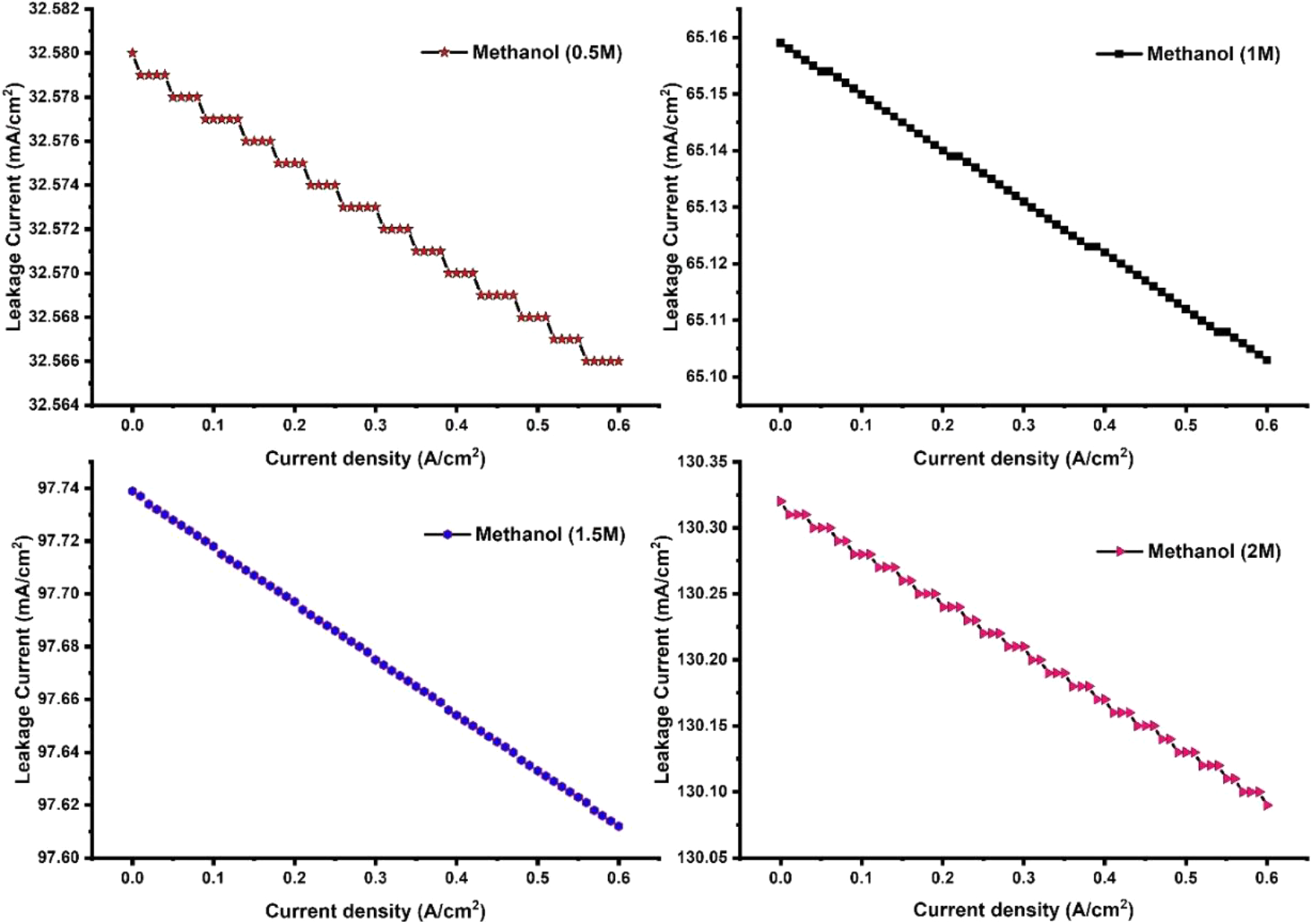
Fig. 3: Effect of methanol feed concentration on the generation of leakage current in a DMFC
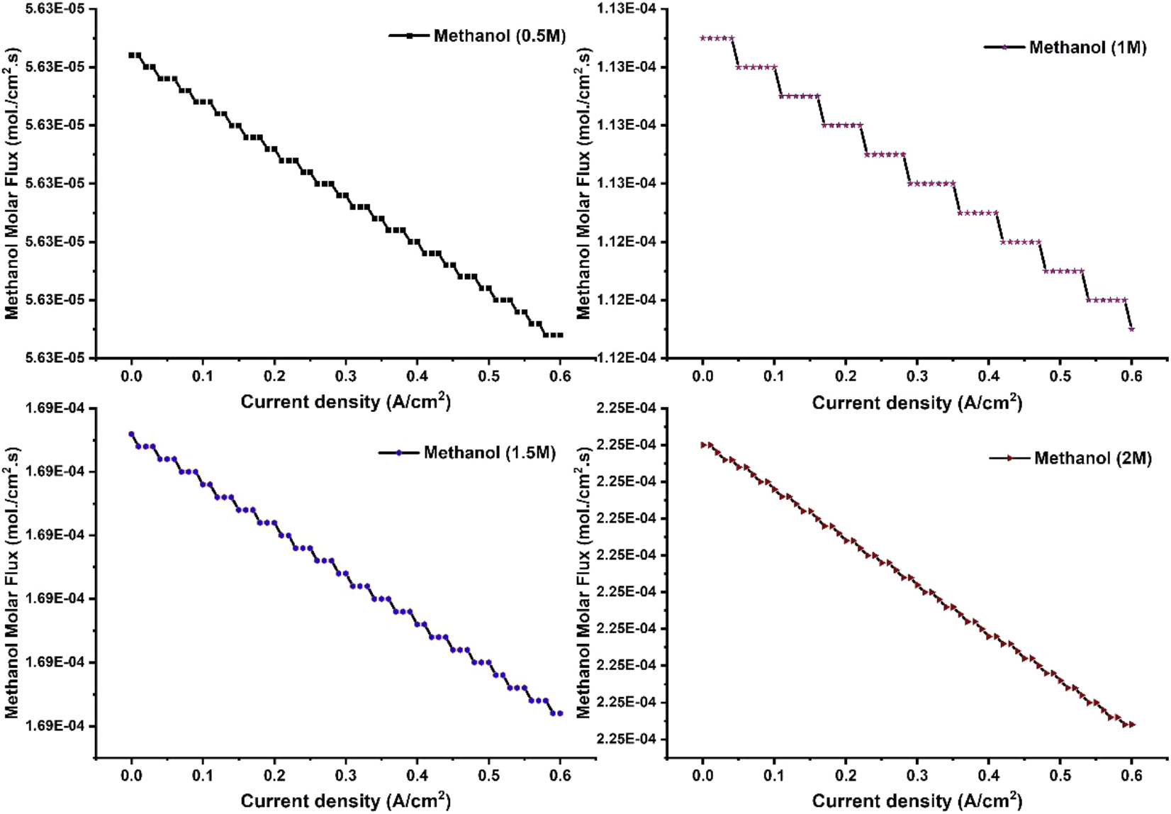
Fig. 4: Predicted molar flux rate of methanol through the membrane. Effect of methanol feed concentration on the fuel cross-over rate
The proposed model was simultaneously solved in a simulated environment and predicted the cell voltage at different methanol feed concentration. The polarization curve of the DMFC predicted at different methanol feed concentration is shown in Fig. 5. The cell voltage increases with the increase of methanol feed concentration. With the increase of methanol concentration in feed side, more amount of methanol is oxidized at anode side. The oxidation of methanol at anode produces more electric current. The electric current is collected by a current collector and stored in an external load. The generation of more electric current enhances cell voltage. The maximum cell voltage was predicted for 2M methanol feed at anode side. However, it was also observed that the increase of methanol feed concentration produces more leakage current. Hence, the methanol feed concentration should be optimized to reduce leakage current. To reduce leakage current, methanol cross-over through the membrane should be minimized. The methanol cross-over through the membrane can be controlled by membrane architectures. The membrane considered in this paper should be modified to enhance its methanol blocking ability. It was also observed that the cell voltage gradually decreases with the increase of current density. With the increase of current density, cell voltage was reduces due to polarization loss. At higher current density, polarization loss was dominated by ohmic loss. To avoid higher voltage loss, cell should be operated at low current density region. However, at lower current density region, cell produces lower power density. It is desirable to operate fuel cell at higher current density region to provide higher power density. Hence, ohmic loss should be minimized to reduce polarization loss at higher current density region. The ohmic loss was caused by the electrolyte resistance of the membrane. The electrolyte membrane with higher proton conductivity reduces electrolyte resistance. Therefore, it is desirable to develop a high proton conducting membrane to reduce electrolyte resistance. Fuel cell operated at a higher current density region as well as methanol feed concentration provides more power density. For better cell performance, fuel cell should be operated at low current density and higher methanol feed concentration. Moreover, it is suggested that the proton conductivity of the membrane should be enhanced to a higher level.
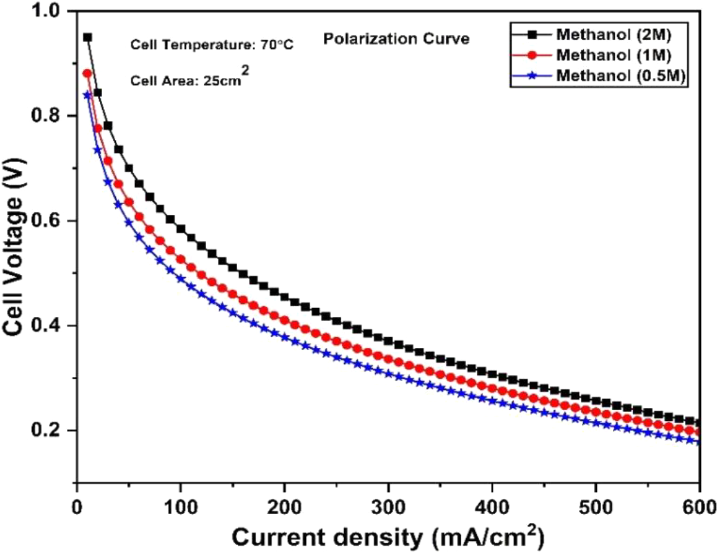
Fig. 5: Prediction of polarization curve for different methanol feed concentration in DMFC
The polarization curve predicted by the proposed model is validated with the experimental data. The experiment was conducted at 70°C and 2M methanol feed at anode side. The validation of model with the experimental data is shown in Fig. 6. The proposed model strongly agreed with the experimental data. The proposed model can be used to predict the polarization curve. The advantage of the proposed model is that it can be used efficiently at a less time.
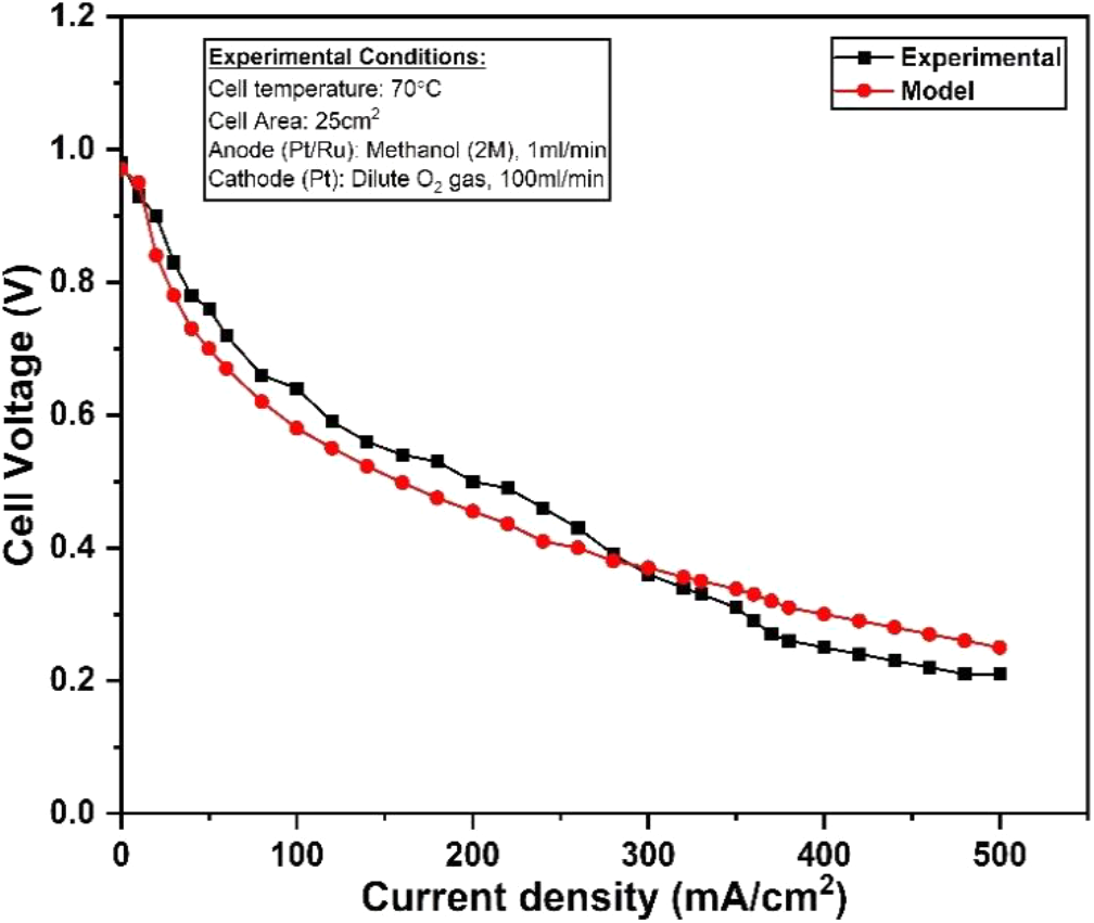
Fig. 6: Validation of model polarization curve with the experimental data for a DMFC operating at 70°C and 2M methanol feed
The experimental data of our work was fitted to a well suited analytical model proposed by the researchers. In a literature, we have found the various modelling approach to predict the cell performance of active DMFC. However, there was a limited work for the analytical modelling of active DMFC. The analytical model proposed by the team of Srivastava et al., and Deng et al., were best suited for our experimental results. The model equation proposed by them were more relevant to our experimental conditions. Therefore, we have considered their analytical model to predict the cell performance of active DMFC. The experimental parameters were fitted to their analytical model and polarization curve was predicted. The polarization curve obtained by fitting the experimental parameters to a various analytical model is shown in Fig. 7. The polarization curve obtained from our proposed model was strongly agreed with the experimental results. It was observed that the model equation proposed in this study is more effective to predict the cell performance with higher accuracy. However, the polarization curve obtained from the proposed model of Srivastava et al., and Deng et al., was not satisfactorily fitted with the experimental results. The model equation proposed by Deng et al., was partially fitted with our experimental results.
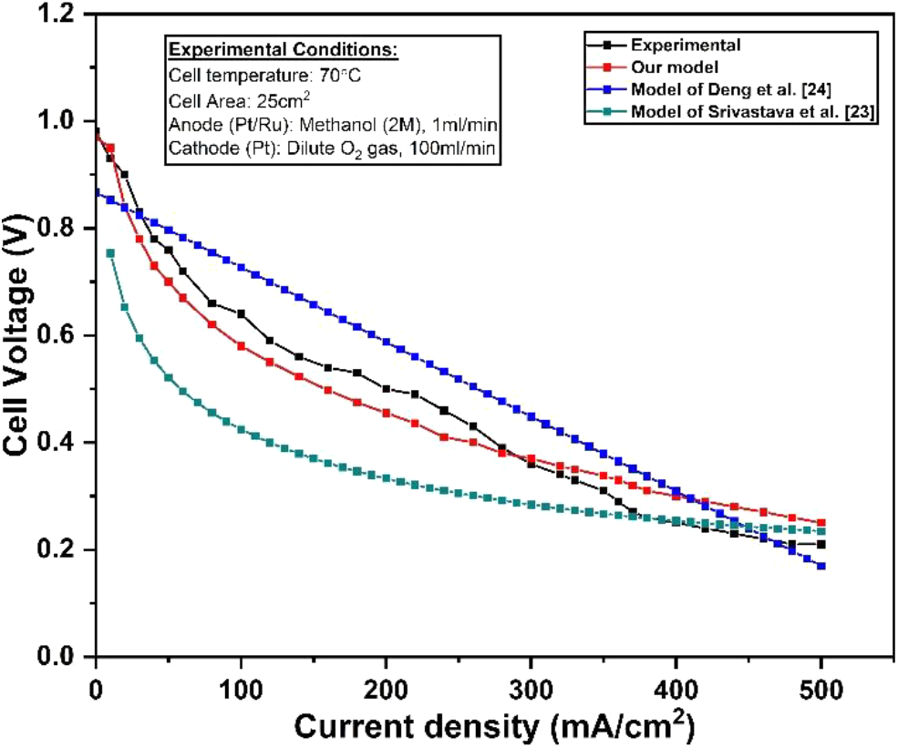
Fig. 7: Comparison of experimental polarization curve with the various models
The analytical model of the active DMFC was proposed to predict the leakage current and polarization curve of the cell. The kinetics of methanol transport and its electrochemical oxidation at AFC was modelled to predict the methanol cross-over rate and leakage current. The methanol molar flux rate increases with the increase of methanol feed concentration in a DMFC. The leakage current of the cell was predicted from the methanol cross-over rate. The supply of highly concentrated methanol at anode side produces more leakage current. The leakage current of the cell was controlled by membrane architecture. The membrane with lower methanol cross-over produces less leakage current. The membrane with lower methanol cross-over is desirable for improving fuel cell performance. The fuel cell operated at higher current density produces less leakage current. However, at a higher current density region; cell voltage degraded due to polarization loss. The polarization loss should be minimized to reduce voltage degradation and improves power density. Fuel cell operated at higher methanol feed concentration and current density region provides higher power density. The proposed model was simultaneously solved to predict the polarization curve of the cell with high accuracy and in a less time. The proposed model strongly agreed with the experimental results and can be used to predict DMFC performance.
1. K. Saikia, BK Kakati, B Boro, A Verma. (2018). Current Advances and Applications of Fuel Cell Technologies, Recent Advancements in Biofuels and Bioenergy Utilization, Singapore: Springer, 303-337. [Google Scholar]
2. R. Murmu, D. Roy, SC Patra, H. Sutar, Senapati. (2022). Preparation and characterization of the SPEEK/PVA/Silica hybrid membrane for direct methanol fuel cell (DMFC), Polymer Bulletin, 79: 2061-2087. DOI: https://doi.org/10.1007/s00289-02103602-3 [Google Scholar] [CrossRef]
3. J. Divisek, J. Fubrmann, K. Gartner, R. Jung. (2003). Environmental aspects of direct methanol fuel cell: Experimental detection of methanol electro oxidation product. Journal of Electrochemical Sources, 150: A811-825. [Google Scholar]
4. R. Murmu, D. Roy, S. Jena, H. Sutar. (2022). Development of Chitosan based hybrid membrane modified with Ionic-Liquid and Carbon Nanotubes for direct methanol fuel cell operating at moderate temperature. Polymer Bulletin. DOI: https://doi.org/10.1007/s00289-022-04246-7 [Google Scholar] [CrossRef]
5. NFI Fauzi, UA Hasran and SK Kamarudin. (2013). Review on utilization of the pervaporation membrane for passive vapor feed direct methanol fuel cell, IOP Conf. Series: Materials Science and Engineering, 50: 012056. DOI: https://doi.org/10.1088/1757-899X/50/1/012056 [Google Scholar] [CrossRef]
6. SK Kamarudin, F. Achmad and WRW Daud. (2009). Overview on the application of direct methanol fuel cell (DMFC) for portable electronic devices. International Journal of Hydrogen Energy, 34(16): 6902-16. [Google Scholar]
7. F. Lufrano, V. Baglio, P. Staiti, V. Antonucci, AS Arico. (2013). Performance analysis of polymer electrolyte membranes for direct methanol fuel cells. Journal of Power Sources, 243: 519–534. [Google Scholar]
8. ZH Wang and CY Wang. (2003). Mathematical Modelling of Liquid-Feed Direct Methanol Fuel Cells. Journal of Electrochemical Society, 150 (4): A508–A519. [Google Scholar]
9. G. Gwak, D. Kim, S. Lee, H. Ju. (2018). Studies of the methanol crossover and cell performance behaviors of high temperature-direct methanol fuel cells (HT-DMFCs). International Journal of Hydrogen Energy, 43(30): 13999-14011. [Google Scholar]
10. M. Zago, A. Casalegno, F. Bresciani, R. Marchesi. (2014). Effect of anode MPL on water and methanol transport in DMFC: Experimental and modelling analyses. International Journal of Hydrogen Energy, 39(36): 21620-21630. [Google Scholar]
11. BL Garciìa, VA Sethuraman, JW Weidner, RE White & R. Dougal. (2004). Mathematical Model of a Direct Methanol Fuel Cell. Journal of Fuel Cell Science and Technology, 1(1): 43. DOI: https://doi.org/10.1115/1.1782927 [Google Scholar] [CrossRef]
12. JP Meyers and J. Newman. (2002). Simulation of the Direct Methanol Fuel Cell - Ii. Modelling and Data Analysis of Transport and Kinetic Phenomena. Journal of Electrochemical Society, 149 (6): A718-A728. [Google Scholar]
13. G. Giacoppo, F. Cipitý and O. Barbera. (2020). Mathematical modelling approaches in direct methanol fuel cells, Direct Methanol Fuel Cell Technology, Book Chapter, 423-441. DOI: https://doi.org/10.1016/B978-0-12-819158-3.00014-8 [Google Scholar] [CrossRef]
14. X. Ren, TA Zawodzinski and S. Gottesfeld. (2000). Methanol transport through Nation Membranes. Electro osmotic Drag Effects on Potential Step Measurements. Journal of Electrochemical Society, 147: 466. [Google Scholar]
15. SR Narayanan, A. Kindler, B. Jeffries-Nakamura, W. Chun, H. Frank, M. Smart, S. Surampudi, G. Halpert. (1995). Performance of PEM liquid feed direct methanol-air fuel cells. The Electrochemical Society Proceedings Series, Pennington, 261-266. [Google Scholar]
16. MK Ravikumar and AK Shukla. (1996). Effect of Methanol Crossover in a Liquid Feed Polymer Electrolyte Direct Methanol Fuel Cell. Journal of Electrochemical Society, 143: 2601. [Google Scholar]
17. SF Baxter, VS Battaglia and RE White. (1999). Methanol Fuel Cell Model: Anode. Journal of Electrochemical Society, 146 (2): 437-447. [Google Scholar]
18. K. Scott, P. Argyropoulos and K. Sundmacher. (1999). A model for the liquid feed direct methanol fuel cell. Journal of Electro Analytical Chemistry, 477: 97-110. [Google Scholar]
19. R. Murmu, D. Roy, H. Sutar, P. Senapati, SC Patra. (2022). Development of the highly performed chitosan based thin film towards the sustainability of direct methanol fuel cell. Polymer-Plastics Technology and materials, 1-24. DOI: https://doi.org/10.1080/25740881.2022.2133616 [Google Scholar] [CrossRef]
20. A.A. Kulikovsky. (2007). Analytical Models of a Direct Methanol Fuel Cell. Advances in Fuel Cell, 1: 337-417. DOI: https://doi.org/10.1016/S1752-301X(07)80011-1 [Google Scholar] [CrossRef]
21. S. Patrabansh. (2013). Dynamic modelling and simulation of a DMFC/UC based hybrid vehicular system, IEEE. DOI: https://doi.org/10.1109/IAS.2013.6682525 [Google Scholar] [CrossRef]
22. R. Murmu, D. Roy, SC Patra, H. Sutar, Choudhary B. (2023). Preparation and characterization of red mu modified chitosan-pva composite membrane for direct methanol fuel cell. Journal of Electrochemical Energy Conversion and Storage, 20(3): 031008. DOI: https://doi.org/10.1115/1.4055693 [Google Scholar] [CrossRef]
23. NK Shrivastava, RB Chadge and SL Bankar. (2017). Modelling and simulation of passive feed direct methanol fuel cell. International Journal of Energy Technology and Policy, 13: 4-8. [Google Scholar]
24. Hao Deng, Jixin Chen, Kui Jiao, Xuri Huang. (2014). An analytical model for alkaline membrane direct methanol fuel cell, International Journal of Heat and Mass Transfer, 74: 376-390. [Google Scholar]
Cite This Article
 Copyright © 2023 The Author(s). Published by Tech Science Press.
This work is licensed under a Creative Commons Attribution 4.0 International License , which permits unrestricted use, distribution, and reproduction in any medium, provided the original work is properly cited.


 Submit a Paper
 Propose a Special lssue
 View Full Text
 Download PDF
 Downloads
 Citation Tools