 Open Access
ARTICLE
Separation Characteristics of Surface Modified Polysulfone Ultrafiltration Membrane using Oxidative Catalytic Polymerization of Aniline
1 University School of Chemical Technology, Guru Gobind Singh Indraprastha University,
Sector 16 C, Dwarka, New Delhi- 110078, India.
2 Department of Polymer Technology, G.N.D. DSEU, Rohini Campus, Rohini,
Delhi-110089, India.
* Corresponding Author: e-mail:
Journal of Polymer Materials 2022, 39(3-4), 283-305. https://doi.org/10.32381/JPM.2022.39.3-4.8
Abstract
The commercially available Polysulfone (PSF) membrane surface was modified by solution polymerization of aniline using different oxidation catalysts i.e., FeCl3, CuCl2, and APS. Modified membranes were then characterized with respect to physio-chemical properties like surface chemistry, porosity, wettability, surface roughness, morphology, etc. It was observed that the hydrophilicity/ wettability of membranes was increased upon surface modification by polyaniline which again depended on the nature of the oxidation catalyst used. Membranes developed using FeCl3 and CuCl2 as oxidants exhibit improved permeation, protein rejection, and antifouling properties, whereas decrement was observed in modified membrane performance using APS as an oxidant. Among all modified membranes, PSF/PANI-CuCl2 membrane demonstrates the most promising performance in terms of higher pure water flux and protein solution permeation flux i.e., 453.3 L/m2 .h and 122.3 L/m2 .h respectively. The PSF/PANI-CuCl2 membrane unveils superior resistance towards bio-fouling in comparison to the other modified membranes. Analytical techniques were used for the characterization of the modified membranes such as ATR, XPS, FESEM, and AFM. Contact angle measurement also supports the fact that PSF/PANI-CuCl2 membrane has a better chemical and physiological attachment to the polysulfone membrane surface.Keywords
Safe and affordable drinking water is crucial to human survival as well as socioeconomic development in society. Therefore, it becomes a global challenge for researchers to provide safe and affordable drinking water to every household. New technologies are emerging regularly to overcome the scarcity of fresh and drinkable water. Membrane technology has evolved during these years as a sustainable alternative to purifying and treating waste water [1-5]. Reverse osmosis, microfiltration, ultrafiltration, and nano-filtration membranes are widely used in industries to get the desired products and for the treatment of wastes [6-9].
Fouling is the most common and major issue that affects the membrane's performance and reduces its operating life. Studies have demonstrated that severe fouling phenomena are observed with the membranes having hydrophobic surfaces which deteriorate the separation efficiency and membrane life[10-15]. Several strategies and methods have been tried to reduce the hydrophobic nature of membrane surfaces for better performance as well as fouling resistance. The most commonly adopted methods are surface grafting, electro-spinning, polymer blending, UV-photo-grafting, surface coating, dynamic forming, and incorporation of hydrophilic agents in the casting solution [16-20].
Tao Wu et al.[21] show enhanced selectivity and fouling resistance of membranes prepared by blending PS-b-PEO and PS-b-PEO-b-PS copolymers. Zhu, L. P. et al. [22] employed poly (DOPA) & heparin, and D'Arcy, J. M. et al [23] used poly (MPC-co- BMA) and MPC to enhance the hydrophilicity of PVDF membrane surfaces using simple dip coating method. Peng, J. et al. [24] reported a significant increase in the hydrophilic nature of the PES membrane surface when poly (ether glycol) methyl ether methacrylate (PEGMA) was grafted on the membrane surface. UV-ozone pretreatment with subsequent grafting and interfacial polymerization for the modification of the PES membrane surface was reported by Liu, S. X. et al. [25]. To improve the surface properties of the PES membrane, Sun, M.et al. [26] added silica-PVP nano-composites into the membrane casting solution. Rana H.et al.[27] modified TFC-RO membrane surfaces via graft polymerization mediated rapidly in the presence of Ce (IV)/PVA redox system.
Polysulfone (PSF) ultrafiltration membranes are extensively employed in various industrial applications like; wastewater treatment, oil-water separation, food processing, dairy, biotechnology, and textile industries [28-32]. Besides separation, purification, and concentration, ultrafiltration membranes are actively found in its applications in removing biological entities such as; bacteria, algae, and pyrogens as well as recovering high-end products from chemical, pharmaceutical, and food industries [33, 34]. Polysulfone membranes have been commonly used in the fabrication of ultrafiltration membranes due to their outstanding chemical stability, heat resistance, mechanical properties, and stability over a wide range of pH [35, 36]. However, the intrinsic hydrophobic nature of polysulfone membranes limits its application for practical industrial operations.
Recent reports [28, 29, 31, 32, 37, 38] reveal an interesting fact that around the globe researchers beautifully incorporate polyaniline with membranes to improve their wettability character. Tunable morphologies of polyaniline enable researchers to explore the new directions of its uses. In the present era, polyaniline is prepared by incorporating metal nanoparticles to increase its application span. Typical synthesis route which integrates Ammonium persulfate as an oxidant has been replaced with many new methods which provide better morphological structures[39-41]. Iron, Copper, Silver, and Gold nanoparticles are immensely adopted as an oxidant in the synthesis of multi-functional polyaniline [42-45]. Some exciting properties such as; low-cost scalable synthesis, corrosion resistance, and excellent thermal and chemical stability enable the researchers to avail this opportunity and use polyaniline in fabricating membranes for large industrial applications [46]. It has been reported that the addition of polyaniline enhances membrane porosity and thus results in higher permeability and better anti-fouling properties [6, 7, 28, 29].
Many researchers [31,37,47-49] added polyaniline at the time of membrane manufacturing via phase inversion and immersion precipitation methods and a significant increase in membrane surface hydrophilicity, as well as an improved anti-fouling feature, was recorded. Whereas researchers like Liu, M. et al. and Fan, Z. et al. modified the surface properties of commercially available membranes using polyaniline by facial polymerization and through the filtration of polyaniline nano-fibers using polysulfone as substrate membrane, respectively [32, 38].
In the present work, surface-initiated polymerization and chemical oxidation polymerization of aniline has been used to alter the surface properties of pure polysulfone membrane. Iron (III) chloride (anhydrous), copper (II) chloride dehydrate, and ammonium persulfate is used as oxidants in the reaction system. The attachment mechanism of the polyaniline layer on the membrane surface and how they influence the performance of modified membranes are thoroughly discussed in the presented manuscript.
Polysulfone UF membrane (MWCO 100 KDa) supplied by Alfa Laval India Private Limited, India. Aniline (99.5%, ACS Reagent), Sodium Hypochlorite Solution with available Chlorine (4-4.99%, RG), Ammonium persulfate (APS) (≥ 98.0%, ACS Reagent), Iron (III) Chloride (Anhydrous ≥ 98.0 %, EG), Copper (II) Chloride dihydrate (CuCl2.2H2O ≥ 99.0%, ACS Reagent) and Methanol (≥ 99.9%) was procured from Merck Germany. Bovine Serum Albumin (BSA) used as a model pollutant was purchased from SRL Pvt. Ltd., India. Hydrochloric Acid (ACS plus Grade) was provided by Thermo Fisher Scientific, India.
Preparation of PSF/PANI-FeCl3 Modified Membrane
In the first procedure, the polysulfone membrane surface was modified via chemical oxidation polymerization of aniline in presence of excess Iron (III) chloride solution and magnetically stirred for about 15 minutes. Subsequently, aniline was added in the molar ratio to Iron (III) chloride (1: 2). The moment aniline is added into the system, the solution changes its color from dark yellow to dark green indicating that the polymerization reaction started. For uniform mixing of reactants, the solution was magnetically stirred for 10 minutes. The pre-compacted membrane is then immersed into this polymer solution and the whole assembly was delicately placed in an orbital shaker with shaking at around 110 rpm at room temperature. The polymerization reaction was continued for 48 hours to complete the reaction.
Preparation of PSF/PANI-CuCl2 Modified Membrane
In this procedure, the polysulfone membrane was dipped into copper (II) chloride dihydrate solution about 1 hour before the polymerization reaction of aniline for the absorption of copper (Cu++) ions on the surface of the membrane. Later, aniline was added into the system in the molar ratio to copper (II) chloride (1:3). Florescent green color of the copper solution immediately changes to dark red as aniline is added into the reaction system due to the initialization of the polymerization reaction. The reaction was continued for 20 hours in an orbital shaker at around 110 rpm for about 20 hours at room temperature. At the end of the polymerization reaction, the reactant solution becomes dark brownish to green.
Preparation of PSF/PANI-APS Modified Membrane
In this polymerization process, APS is dissolved thoroughly in 1N hydrochloric acid (HCl) and then aniline was added into the system with a molar ratio of aniline to APS as 1:0.6. As oxidant and monomer were uniformly mixed, sodium hypochlorite solution (NaOCl) (Aniline to NaOCl = 1:0.55) was incorporated as an activator to speed up the rate of reaction. As soon as NaOCl was added the color of the solution changed from yellowish to dark green. At this stage, the polysulfone membrane was placed into the polymer solution and kept for about 6 hours in an orbital shaker at around110 rpm at 3-4°C to achieve maximum polymerization.
Measurement and Characterization
All the membranes including PSF, PSF/PANI-FeCl3, PSF/PANI-CuCl2 and PSF/PANI-APS embranes are characterized by using different analytical techniques. Before characterization, all membrane samples were kept at 45°C in a vacuum oven for the vaporization of excess moisture for 24 hours. Attenuated Total Reflectance-Fourier Transformed Infrared spectroscopy; ATR-FTIR, is employed to confirm polyaniline attachment on polysulfone membrane surfaces. Spectra for each membrane are collected over the range of 400- 5000 cm-1 by using Bruker-3000 Hyperion Microscope with Vertex 80 FTIR System, Germany. X-ray photoelectron spectroscopy (XPS), is used to analyze the chemical state of elements present in the surfaces of PSF, PSF/PANI-FeCl3, PSF/PANI-CuCl2, and PSF/PANI-APS membranes. Omicron ESCA (Electron Spectroscope for Chemical Analysis), from Oxford Instrument Germany, is employed to get spectra, and an Al anode having 1486.7 eV energy is used for samples. The angle between the analyzer and the source was kept at approximately 85 degrees. The elemental composition and their distribution on the membrane surfaces are recorded by Ziess Model EVO40 scanning electron microscope equipped with an energy-dispersive X-ray spectrophotometer. The extent of water-loving nature of membrane surfaces is estimated by measuring Contact Angle. The sessile drop method is used for the calculation of static contact angles of the membrane & all the results are recorded on Kruss Drop Shape Analyzer DSA25. An average of five contact angles are reported that were taken from different positions on the membrane surface. The effect of polyaniline incorporation, using different polymerization techniques, on the PSF membrane surface is analyzed via estimation of surface roughness. Atomic Force Microscopy; AFM is used to get the surface roughness parameters like, average roughness and route mean square roughness. Visualization of surface roughness is obtained in 3-D view images. Structural morphological changes occurring due to different oxidation polymerization techniques are recorded via FESEM analysis by using Nova Nano FE-SEM 450 (FEI) having resolution: 1.4 nm at 1 kV (TLD-SE) & 1 nm at 15 kV (TLD-SE). Surface and cross-sectional view images of PSF, PSF/PANI-FeCl3, PSF/PANI-CuCl2, and PSF/PANI-APS are taken and the value of average pore sizes and pore size distribution curves are obtained. For capturing a cross-sectional view of membranes, each membrane sample was cracked by using liquid nitrogen.
To evaluate the performances of polysulfone and membranes modified with different polymerization techniques, a batch-cell membrane filtration unit was employed. The setup allows a disc shape flat-sheet membrane of a diameter of 7.5 cm which provides an effective filtration area of approximately 33 cm2. The feed chamber has a total capacity of 500 ml & is provided with a stirrer for the uniform mixing of solutes and to reduce the chances of agglomeration of foulants near the membrane surface. Transmembrane pressure was maintained via nitrogen. Each membrane was soaked in double distilled water before use. All the permeability experiments were conducted with pre-compacted membranes to stabilize the membrane thickness. Pre-compaction was done at a pressure of 50 psi i.e., higher than the operating pressure.
Pure water flux was calculated for PSF, PSF/PANI-FeCl3, PSF/PANI-CuCl2, and PSF/PANI-APS membranes to evaluate the effect of surface modification. All permeability experiments were carried out at room temperature and maintained trans-membrane pressure of 20 psi. The formula used for calculating pure water flux:
Where J denotes the pure water flux having SI units L/m2.h, V is the volume collected over a specific period of time in L, S is the effective membrane surface area available for filtration in m2 and t denotes the time taken for collecting a sample in hours.
The fouling analysis is conducted for the estimation of the rejection ability and anti-fouling properties of polysulfone membranes along with the membranes developed by adopting different schemes. Bovine Serum Albumin (BSA) is a standard protein that is commonly used by researchers for fouling studies and we have also chosen BSA as a fouling agent. For fouling experiments, the pure water feed is changed to a protein solution having a strength of 0.5 gm/L and the pH was maintained at 4. UV-spectrophotometer estimated the concentrations of protein present in feed and permeate. BSA shows a sharp absorption peak at a wavelength of 478 nm. Rejection can be calculated as:
Where R is the rejection in percentage (%), CF and CP are the concentrations of protein in the feed and permeate; respectively.
The anti-fouling ability for each membrane can be defined by Flux Recovery Ratio (FRR), Irreversible Flux Decline Ratio (IFR), and Relative Flux Reduction Ratio (RFR) and can be calculated as:
Where J, Jf, and Jp denote the pure water flux, pure water flux after fouling, and flux during protein permeation in L/m2.h; respectively.
Preparation and Structural Characteristics of the Membrane
The polysulfone membranes have been modified by in-situ polymerization of aniline at different molar ratios in DD water at different temperatures depending on the type of oxidant used in the reaction process. The oxidative polymerization of aniline is a complex dynamic process where the pH of the reaction medium as well as the oxidative potential of reactants plays an important role in the reaction process. The oxidative polymerization reaction process described by Wei et al.[50] where oxidation of the monomer nitrogen atom first takes place followed by oxidation of the end nitrogen atom of oligomer and polymer.
The polymerization reaction proceeded on the surface of the membrane for 48 hours to complete the reaction process. In this process, the monomer aniline was oxidized to form radical cations which then form a dimer and ultimately form a linear polyaniline structure in the subsequent oxidation reaction. During the reaction process, the changing of color indicates the confirmation of the polymerization reaction. The color of the membrane successively changes from white to dark blue then black depending on the amount of monomer present in the feed composition which is increased from 0% to 10%.
To ensure the attachment of polyaniline on the polysulfone membrane surface, attenuated total reflectance-Fourier transmitted spectra were taken for PSF, PSF/PANI-FeCl3, PSF/PANI-CuCl2 and PSF/PANI-APS membranes, Figure 1. For pure polysulfone (PSF) membrane, the characteristic absorption band appeared at 1106 cm-1 corresponds to strong C-O stretching, bands developed at 1293 cm-1 and 1150 cm-1 are due to the strong asymmetric and symmetric S=O stretching, while absorption bands found at 1585 cm-1 and 1487cm-1 indicate aromatic (in-ring) C-C stretching and finally, band at 1660 cm-1 is due to the vibrational stretch of C=O[52, 53]. Absorption bands obtained at 1600 cm-1, 1550 cm-1, and 1450 cm-1 show the stretching vibrations of quinonoid and benzenoid rings. Absorption bands appearing around 1300 cm-1 and 1250 cm-1 are due to the vibrations of the C-N bond. The intense peak present at 831 cm-1 in PSF/PANI-FeCl3 spectrum corresponds to aromatic C-H deformation in linear polymer backbone [39, 45]. In PSF/PANI-APS membrane's spectrum, the existence of a very strong and sharp peak around 1120 cm-1 indicates the presence of electronic charge in the quinonoid structure of the polymer chain [41]. The presence of copper ions in the case of PSF/PANI-CuCl2 influences the amino and imino bonds in the polymer matrix and it is indicated by the lower energy shift of the at peak 1362 cm-1[54]. A strong vibrational band at 1414 cm-1 and a shoulder peak at 1680 cm-1 is observed due to the stretching of Phenazine-type segments. During oxidative cyclization (intermolecular) of branched oligoaniline and polyaniline, Phenazine type segments are formed [43, 44]. A strong band consisting of sharp peaks around 1150 cm-1 for each membrane can be assigned to the stretching of charged polymer units -B-NH+=Q- and/or B-NH+o-B and is related to the electron delocalization in the polymer chain [44]. The conversion of monomer into the polymer was characterized by ATR-FTIR spectra and modification of the surface membrane was observed by chemical interaction of the oxygen atom of O=S=O group present in polysulfone film with hydrogen atom of HN-group present in polyaniline through hydrogen bonds. The coating of polyaniline on the surface of the polysulfone membrane was confirmed by shifting of symmetrical and asymmetrical O=S=O stretching band of polysulfone film from 1148cm-1, 1238cm-1 into 1150cm-1, 1241cm-1 respectively as shown in Figure 1.
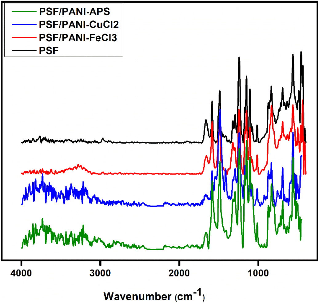
Figure 1. ATR Spectra of PSF, PSF/PANI-FeCl3, PSF/PANI-CuCl2 and PSF/PANI-APS membranes.
Based on the FTIR analysis, the Schematic illustration of the synthesis process of surface modification of polysulfone membrane by polyaniline is shown in Figure 2. During the polymerization of aniline using copper chloride as an oxidizing agent, every step is associated with a release electron thereby reducing the Cu2+ ion to Cu+ ion and producing PANI-emeraldine salt (PANI-ES), as shown in Figure 2(b). The Cu+ ion present in the reaction medium binds with the chain nitrogen of the polyaniline to form a copper complex. The presence of copper ions in modified PSF/PANI-CuCl2 membrane has also been confirmed by Elemental mapping results and EDX spectra in Figure 8 and 9. Polymerization of aniline using ammonium persulfate as a strong oxidizing agent with oxidation potential 2.01V is capable of oxidizing all intermediates of PANI during polymerization reaction at lower pH. The polymerization reaction of polyaniline is shown in Figure 2(c) under temperatures 3-4°C. In an acidic medium and at low temperatures the monomers are added by electrophilic substitution accompanied by the release of two protons. Initially, polyaniline forms PANI-Emeraldine salt (PANI-ES), which is unstable and converted to PANI-Emeraldine base (PANI-EB) upon washing with an appropriate amount of base solvent, which is stable at room temperature [51].
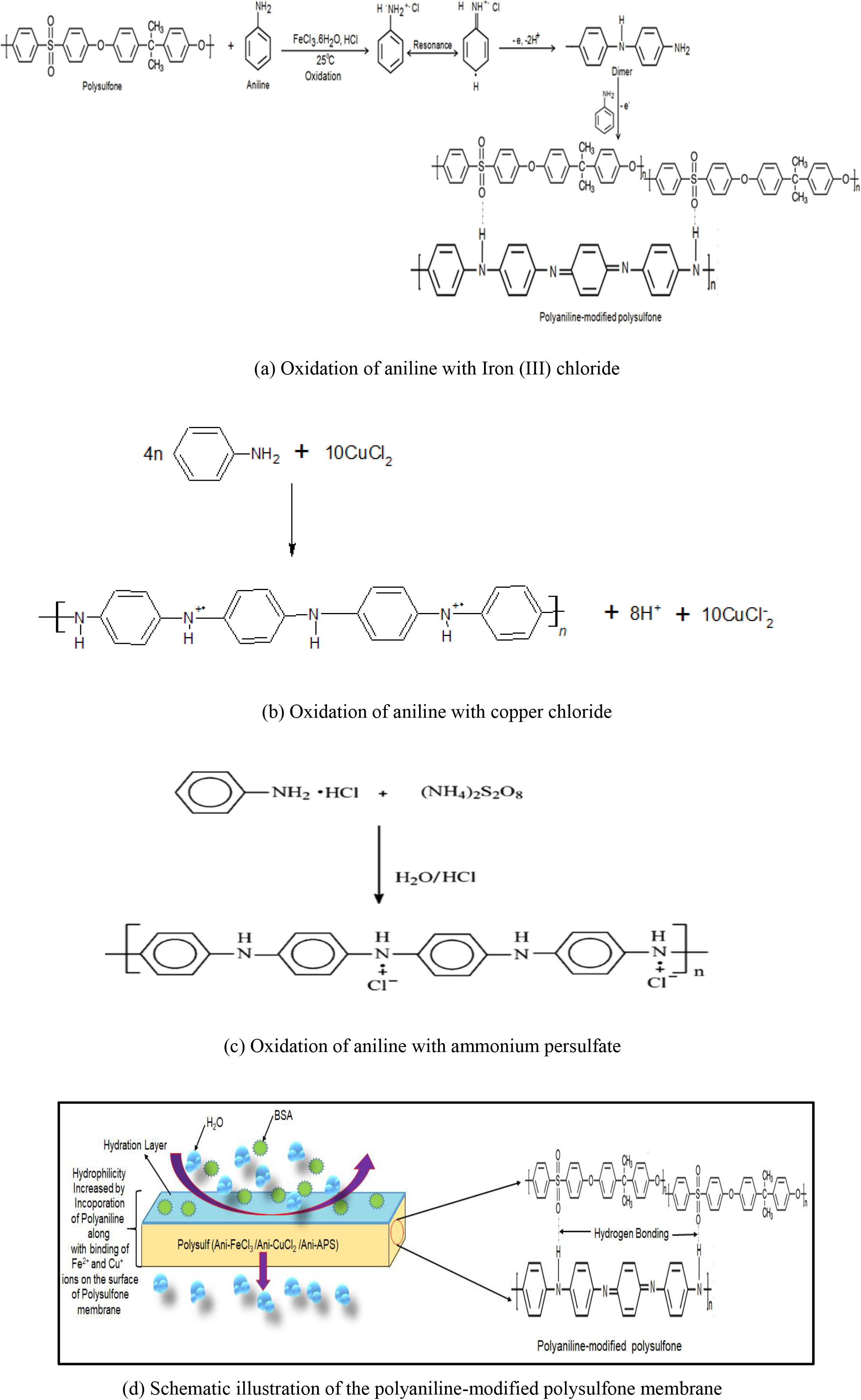
Figure 2. The polymerization schemes and schematic illustration for the modification of the polysulfone membrane
The surface chemical composition is determined by XPS for all developed membranes as it has a great effect on the wettability feature of the membrane. Figure 3 displays the XPS spectra taken for pure PSF and all modified membranes. The wide scan XPS spectra of pure polysulfone (PSF) membrane revealed three prevailing peaks centered at 283.7eV, 166.9 eV, and 530.3 eV, which are endorsed to carbon (C 1s), sulfur (S 2p), and oxygen (O 1s), correspondingly[18, 36, 55]. The XPS spectrum of PSF/PANI-FeCl3, PSF/PANI-CuCl2, and PSF/PANI-APS membranes have similar spectra to the PSF membrane except for the characteristic peak of polyaniline. The polyaniline coating over the modified membrane surfaces can be depicted by the N 1s spectra as displayed in Figure 3 (a). It can be resolved into three dissimilar peaks of nitrogen forms that are present in polyaniline. The centered crest at 397.24 eV may be due to a slight surface contact amongst nitrogen/ligand ions, the diffused peak allocated at 398.35 eV owing to pyridinic-N and a feeble peak at 400.09 eV may be due to pyrrolic-N interactions present there in polyaniline basic structure[41]. In the case of PSF/PANI-CuCl2 membrane, the binding energies at 933.1 eV and 198.9 eV in the spectrum correspond to Cu 2p3/2 and Cl 2p, which are characteristic features of the zero valent copper (Cu0) and divalent chloride ions (Cl2-)[43]. Whereas, PSF/PANI-FeCl3 membrane's spectrum displayed the narrow and sharp characteristic peaks of carbon and oxygen, as well as the frail signal of nitrogen and iron (Fe 2p). The binding energies at 710.56 eV, 532.46 eV, 397.24 eV, and 284.2 eV are allocated to iron (Fe 2p), oxygen (O 1s), nitrogen (N 1s), and carbon (C 1s) spectra peaks, in that order [39, 45]. XPS spectrum of PSF/PANI-APS membrane displayed the existence of N 1s peak which can be resolved into three different components originated at 399.6 eV, 400.8 eV, and 402.3 eV, the foremost peak accredited to -NH- and the other crests attributed to positively charged nitrogen ion [56-58]. As the membrane has been polymerized in 1 M HCl solution, polyaniline is predictable to be in its positive charge stage. When comparing the oxygen spectrum of the PSF membrane to the O 1s spectra of the polyaniline-modified membranes, a shift in binding energy is observed toward higher values in the presence of polyaniline. The higher binding values suggest the interactions between the -SO3- and -NH2+ functional groups[59-61]. Also, the intensity of sulfur peak in the PSF/PANI-FeCl3 membrane is diffused owing to the occurrence of the thicker polyaniline coating over its surface. These spectroscopic results verified that the polyaniline layer had been efficiently incorporated into the surface of modified membranes. The presented XPS results are supported by ATR-FTIR results as well.
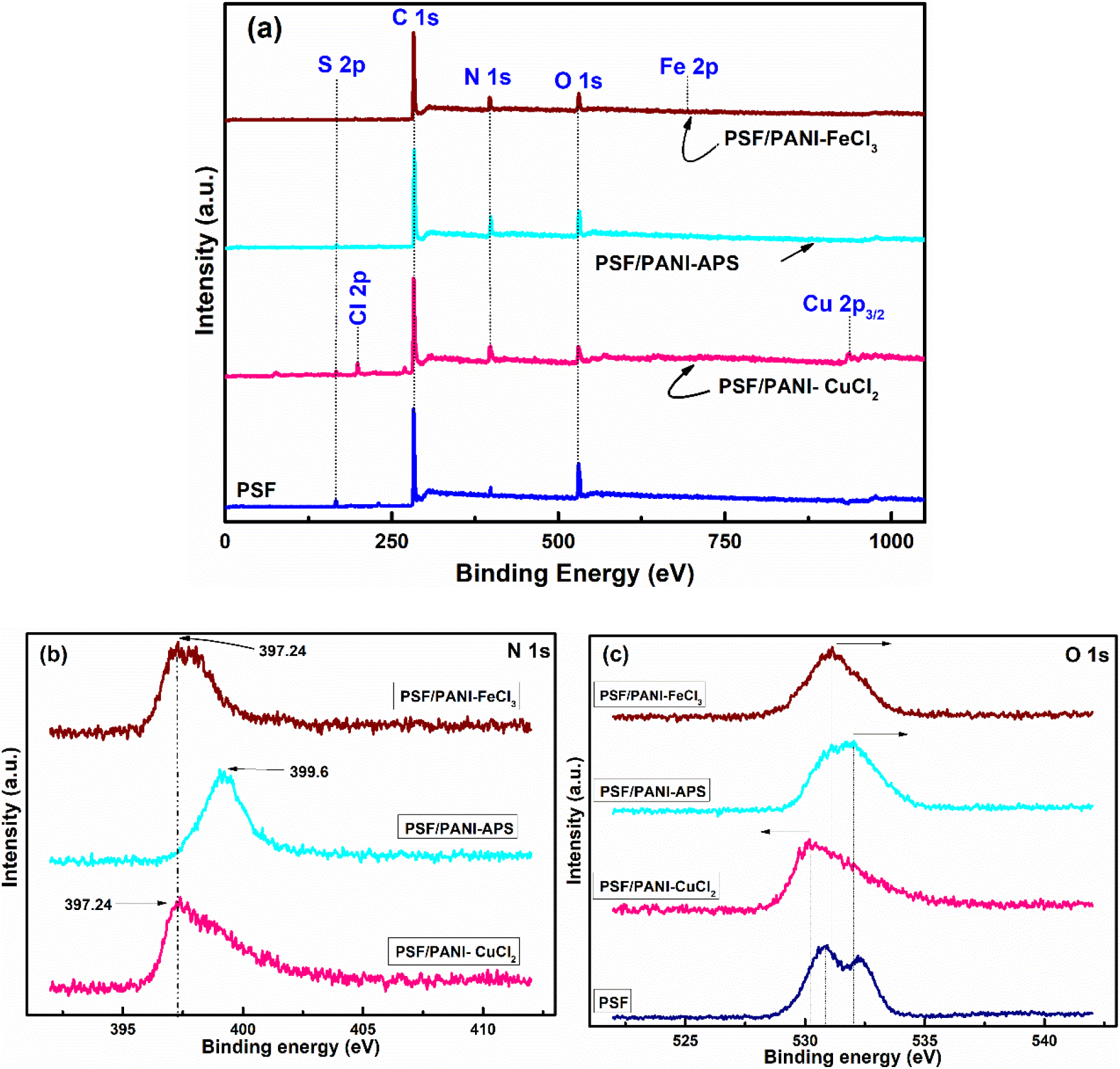
Figure 3. (a) Survey spectra, (b) N 1s spectra, and (c) O 1s spectra for PSF, PSF/PANI-FeCl3, PSF/PANI-CuCl2 and PSF/PANI-APS membranes.
Hydrophilic Properties of the Membrane
The main objective of decorating polysulfone membranes with polyaniline is to alter its hydrophobic surface [6]. Contact angle values of PSF, PSF/PANI-FeCl3, PSF/PANI-CuCl2, and PSF/PANI-APS membranes give an idea about the differences that appeared in the wettability feature of each membrane. Figure 4 represents that the incorporation of polyaniline lowers the contact angle of the membrane surface and can be directly correlated with hydrophilicity and flux enhancement[62]. Among the three procedures adopted, PSF/PANI-CuCl2 membrane shows the least value of contact angle, which is 41.98°, while for the PSF/PANI-FeCl3 and PSF/PANI-APS membranes, the values are 43° and 51.97° respectively. Although in comparison to PSF, the membrane contact angle is significantly lowered but in-spite of having a similar dose of monomer, there is a comparable difference in the values of contact angle for each modified membrane. If we observe closely, the reaction involved in preparing PSF/PANI-FeCl3 and PSF/PANI-CuCl2 membranes were completed in 48 hours and 24 hours; respectively [63,64]. While in the case of the PSF/PANI-APS membrane, the polymerization reaction was completed in only 6 hours due to the presence of NaOCl as an activator/initiator. The wettability of modified membranes enhances due to the presence of polyaniline on the membrane surface but the interaction of the developed polyaniline layer with the pores of a pristine membrane can be revealed only by FESEM analysis. The uniformity of polyaniline attachment plays a vital role in the overall performance of modified membranes and that was thoroughly analyzed and discussed via FESEM results presented in the later part of the manuscript.
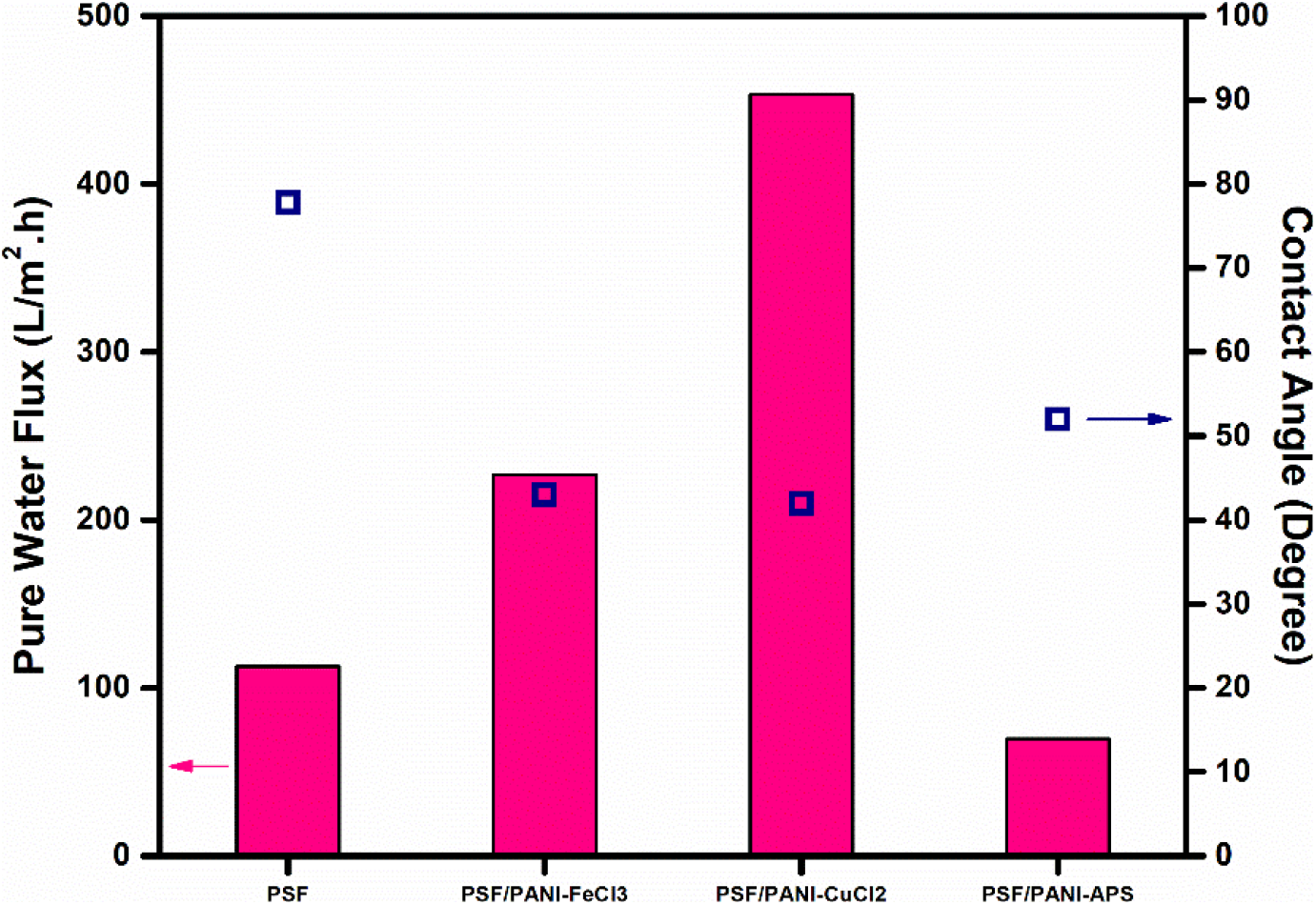
Figure 4. Average pure water flux and Contact angle.
Morphology on Membrane Characteristics
In this study, polysulfone membranes were in-situ polymerized with aniline to improve the membrane's structure and surface morphology. The 3-D AFM images membrane was shown in Figure 5. The image consisting bright points (peaks/bulges) and dark points (valleys), for PSF, PSF/PANI-FeCl3, PSF/PANI-CuCl2, and PSF/PANI-APS membranes. The addition of polyaniline on the polysulfone membrane surely increases the surface roughness of pristine membrane and which is visible from AFM images. Table 1 represents the roughness data for all the membranes in terms of average roughness (Ra) and root mean square roughness (Rq), all in the nanometer range. Membrane surface roughness attributes its effect in terms of permeation flux and fouling properties of the membrane[65, 66]. Higher surface roughness values indicate that the effective filtration area is enhanced and will assist more water to permeate during filtration[7, 67]. Higher membrane permeability decorated with polyaniline will result from improved surface roughness. Another aspect related to higher membrane surface roughness is the effect of membrane-solute interaction that governs the anti-fouling resistance of the membrane[68-69].
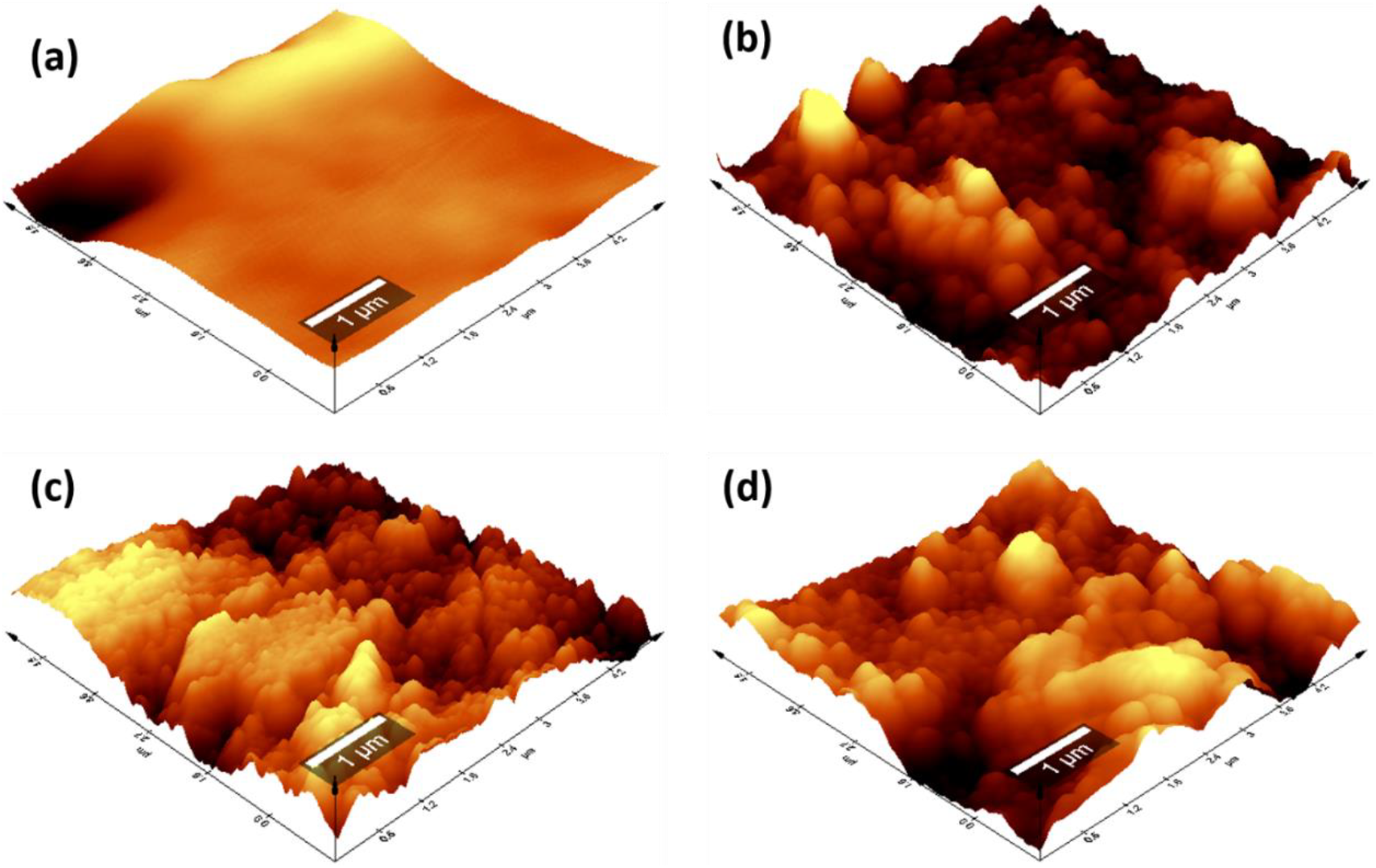
Figure 5. 3-D AFM images: (a) PSF, (b) PSF/PANI-FeCl3, (c) PSF/PANI-CuCl2, and (d) PSF/PANI-APS membranes.

The incorporation of hydrophilic modifiers not only increases surface roughness but also reduces the interaction between solute particles and the membrane surface and improves membrane resistance toward fouling[70].
FESEM surface view images of PSF, PSF/PANI-FeCl3 PSF/PANI-CuCl2, and PSF/PANI-APS are presented in Figure 6. Membranes developed via different polymerization methods have fibrous structures on their surface while in the case of pure polysulfone membrane, there is no sign of fibers. Reported literature suggested that the incorporation of polyaniline increases the surface hydrophilicity of membrane surfaces[7]. Physical morphology is clearly shown in surface view images of all membranes and confirms that polyaniline is attached to the surface of polysulfone membranes in form of a thin porous layer. The existence of this porous layer enhances the surface roughness Figure 5 and also improves the membrane surface hydrophilicity Figure 4 and these results provide the basis for higher flux values and better rejection ability of modified membranes. A cross-sectional view of all membranes was captured for the estimation of the distribution of pores and the average pore size is shown in Figure 7. Data presented in Table 2 shows the average pore size of pristine membranes modified with different polymerization schemes. As we can see, PSF/PANI-FeCl3 and PSF/PANI-CuCl2 membranes have a surface with an average pore size that is greater than the pore size of the PSF membrane, while for PSF/PANI-APS membrane the developed polyaniline layer has comparatively lower pore size. Cross-sectional images of polyaniline-modified membranes demonstrate that PSF/PANI-FeCl3 and PSF/PANI-CuCl2 membranes have a thin clear porous layer while a comparatively denser layer is seen in the case of PSF/PANI-APS membrane. he presence of sodium hypochlorite solution accelerates the polymerization rate and the reaction is completed in very less time. Lower pore size and denser layer of polyaniline may result due to the rapid polymerisation which influences its wettability and separation performance.While in the case of PSF/PANI-FeCl3 and PSF/PANI-CuCl2 membranes, the polymerization reactions proceed at a very slow rate providing proper adsorption of oxidants and anchoring uniform porous polyaniline layer on the surface of the pristine membrane[63, 64]. Elemental mapping results and EDX spectra in Figure 8 and 9, also confirm the presence of metal ions (Fe and Cu) on the surface of the modified membranes.
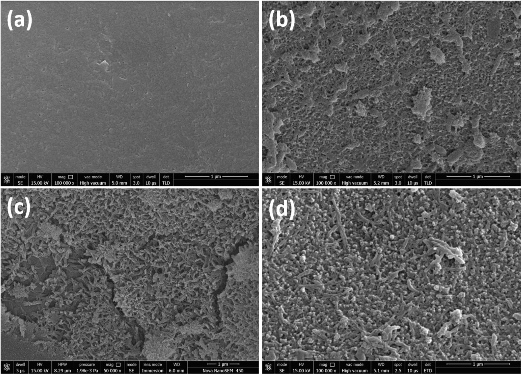
Figure 6. FESEM surface view of (a) PSF, (b) PSF/PANI-FeCl3, (c) PSF/PANI-CuCl2, and (d) PSF/PANI-APS membranes.
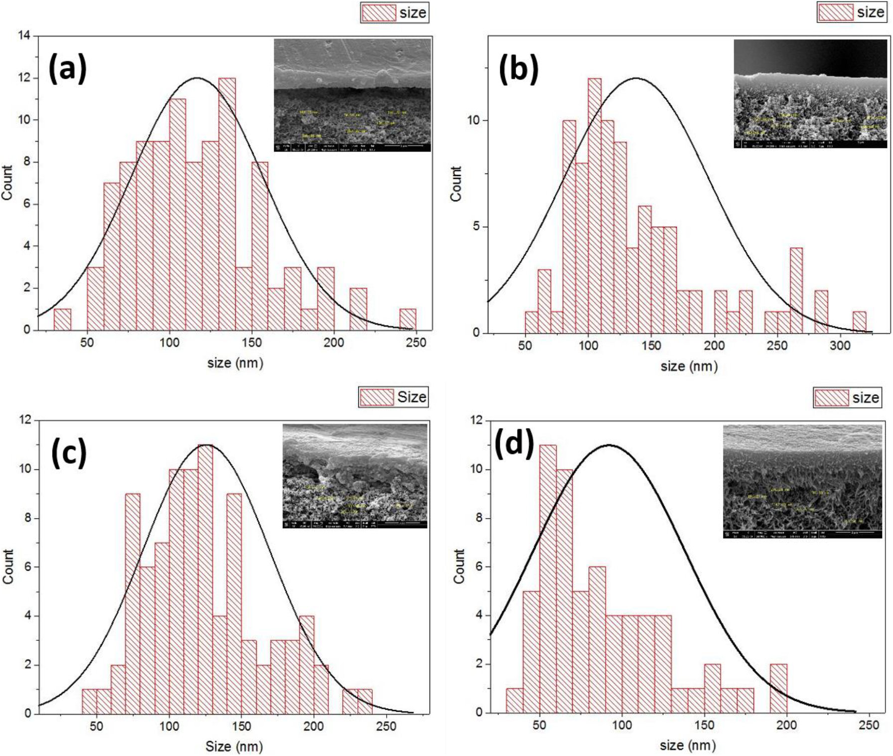
Figure 7. FESEM cross-sectional view & pore size distribution curves of (a) PSF, (b) PSF/PANI-FeCl3, (c) PSF/PANI-CuCl2 and (d) PSF/PANI-APS membranes.

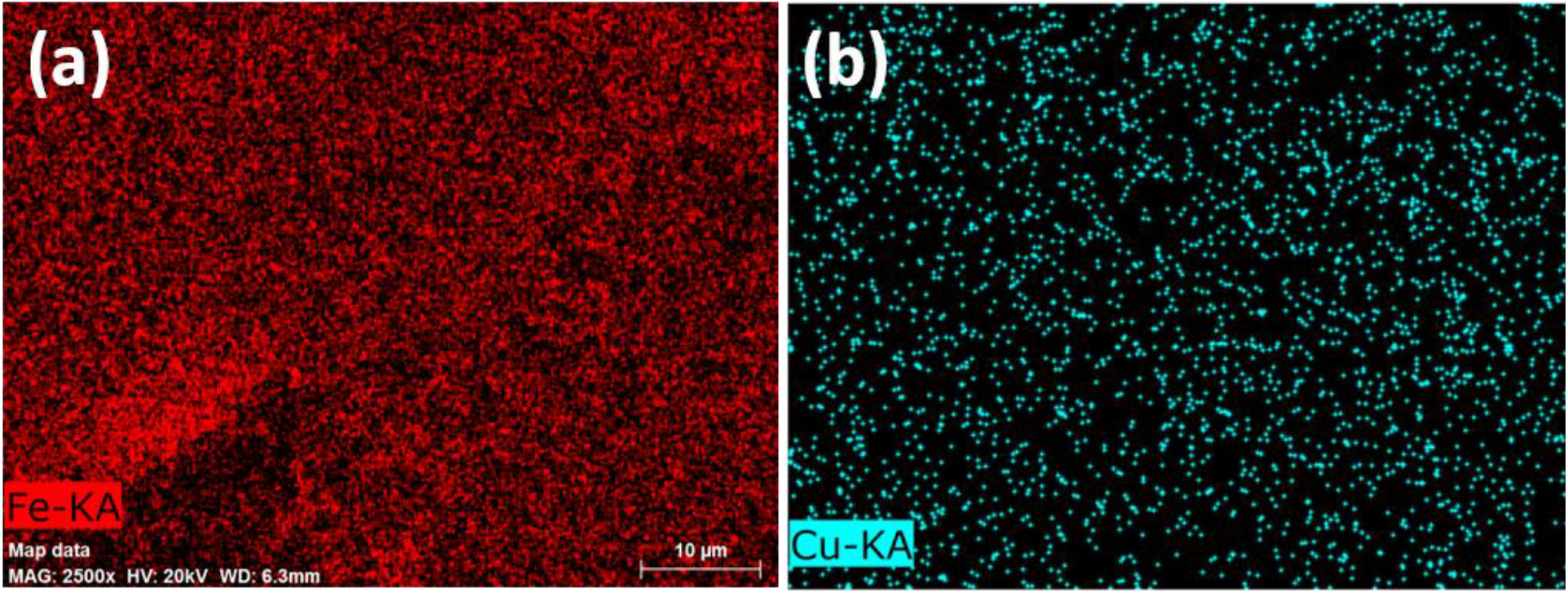
Figure 8. Elemental mapping images; (a) Iron distribution & (b) Copper distribution for PSF/PANI-FeCl3 and PSF/PANI-CuCl2 membranes; respectively.
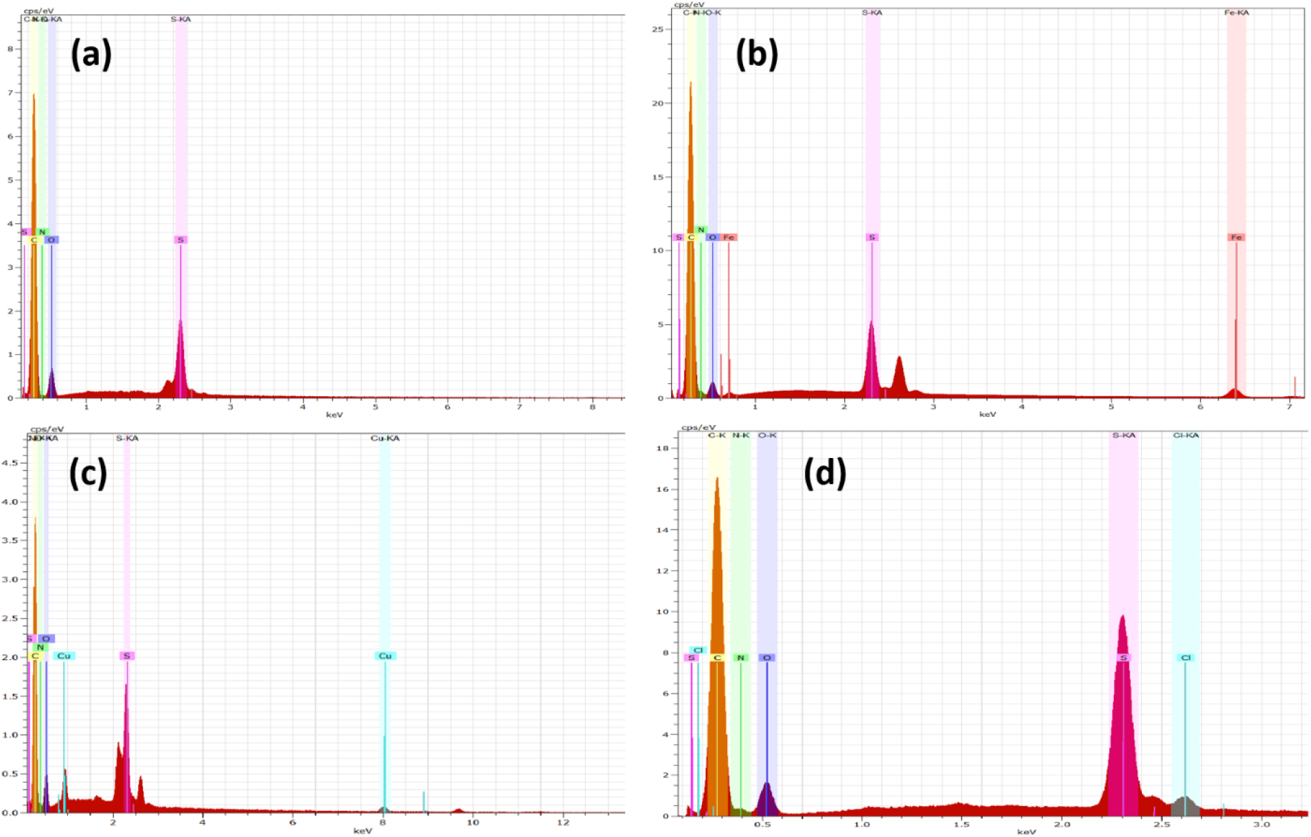
Figure 9. EDAX Spectra for (a) PSF, (b) PSF/PANI-FeCl3, (c) PSF/PANI-CuCl2, and (d) PSF/PANI-APS membranes.
Assessing the Permeability and Protein Resistance on the Membranes
Figure 10 shows time-dependent pure water flux trends for pure polysulfone as well as each membrane modified with polyaniline. PSF/PANI-FeCl3 and PSF/PANI-CuCl2 membranes show much higher values of pure water fluxes. While in the case of the PSF/PANI-APS membrane, pure water flux decreased significantly over the period of 60 minutes. In a fact, the observed flux was lower than the pure water flux of the PSF membrane. Despite improved wettability and increased surface roughness, PSF/PANI-APS membrane shows lower permeability due to the slight difference in the preparation method. PSF/PANI-FeCl3 and PSF/PANI-CuCl2 membranes were developed in the presence of excess amount of oxidants and the rate of polymerization is quite low. Excess amounts of oxidants provide more adsorption of metal ions on the membrane surface and hence properly interlinked pore structures and the uniform coating was obtained[63, 64]. While PSF/PANI-APS membrane was prepared by rapid polymerization of aniline using NaOCl as an activator/initiator. As a result of rapid polymerization, a comparatively non-uniform polyaniline layer is attached to the polysulfone membrane surface which causes an unintentional pore blockage and causes significant flux decline. Permeate flux during protein filtration is presented in Figure 11. Each membrane shows a sudden decrease in permeate flux for an initial 10 minutes span, but after that, a gradual decline in flux was noted. PSF/PANI-CuCl2 membrane maintained higher permeability even for protein filtration while PSF/PANI-FeCl3 and PSF/PANI/APS membranes have significantly reduced flux values.
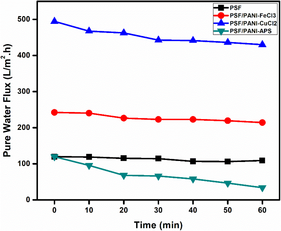
Figure 10. Time-dependent pure water fluxes (@20 Psi) for (a) PSF, (b) PSF/PANI-FeCl3, (c) PSF/PANI-CuCl2 and (d) PSF/PANI-APS membranes.
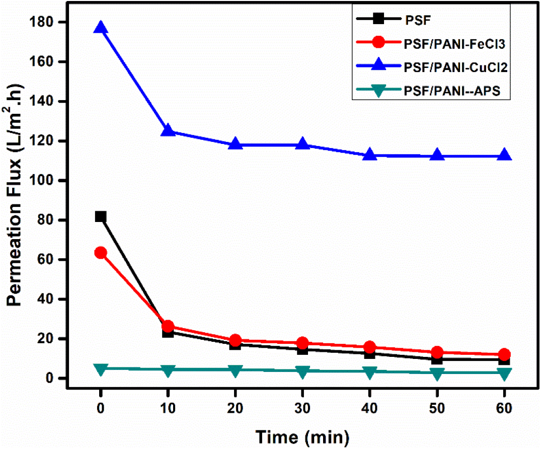
Figure 11. Time-dependent permeate fluxes (@20 Psi) for (a) PSF, (b) PSF/PANI-FeCl3, (c) PSF/PANI-CuCl2 and (d) PSF/PANI-APS membranes; BSA concentration 0.5 gm/L.
In Figure 12, PSF/PANI-FeCl3 and PSF/PANI-APS membranes show better protein rejection values due to their improved surface properties but the average permeate flux values are almost similar and lower than that of pure membrane; respectively. The amount of oxidant absorbed on the surface of the membrane becomes the most prominent cause behind the better performance of PSF/PANI-CuCl2 membrane in terms of rejection percentage and average permeate flux while protein filtration. EDAX results presented in Table 2, confirm that PSF/PANI-CuCl2 membrane surface has more copper content in comparison to the iron content present in PSF/PANI-FeCl3 membrane and this enables the membrane surface to develop a more uniform and porous layer of polyaniline.
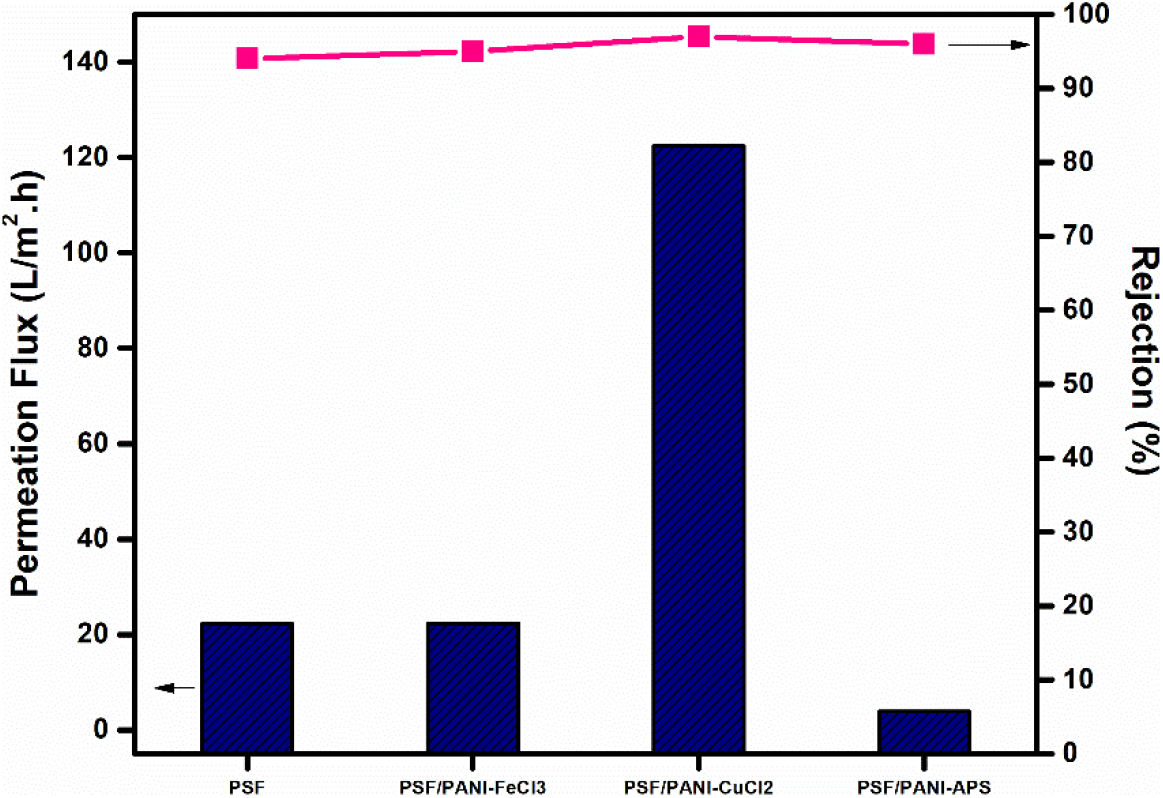
Figure 12. Average permeation flux during protein filtration and Rejection comparison.
Normalized flux curve; Figure 13, obtained for each membrane shows that a sharp and significant reduction in flux values is obtained for PSF and PSF/PANI-FeCl3 membranes but comparatively more subtle behavior in flux declining trends are recorded for PSF/PANI-CuCl2 & PSF/PANI-APS membranes. Figure 14, Anti-fouling studies reveal that PSF/PANI-CuCl2 membrane shows superior results in terms of irreversible flux decline ratio and relative flux reduction ratio. While in the case of the PSF/PANI-FeCl3 membrane, only IFR values are slightly lowered and PSF/PANI-APS membrane shows poor anti-fouling properties. The existence of more copper ions on the membrane surface in the case of PSF/PANI-CuCl2 membrane provides a basis for better and uniform attachment of polyaniline on the surface of the pristine membrane and due to this much higher permeability, better rejection ability, and superior anti-fouling properties are gained.
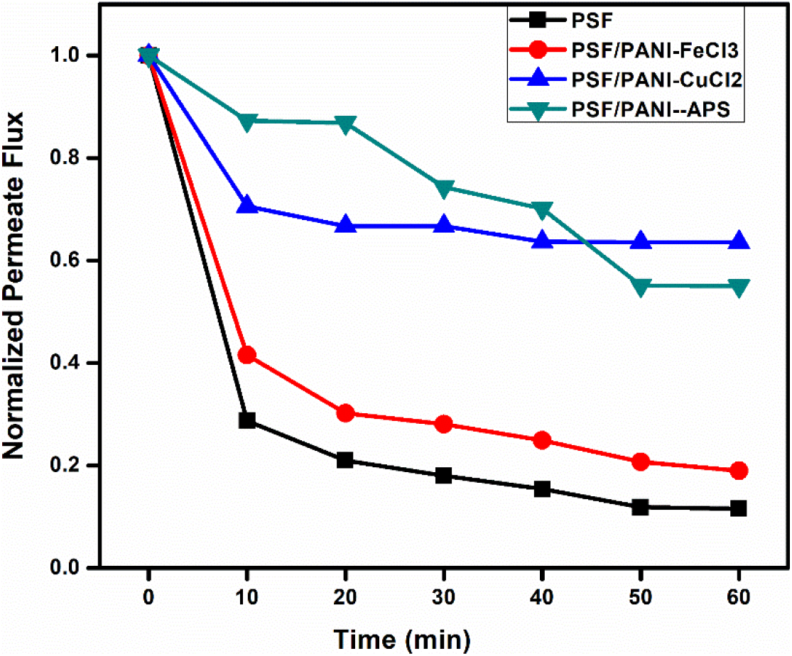
Figure 13. Normalized fluxes for (a) PSF, (b) PSF/PANI-FeCl3, (c) PSF/PANI-CuCl2, and (d) PSF/PANI-APS membranes.
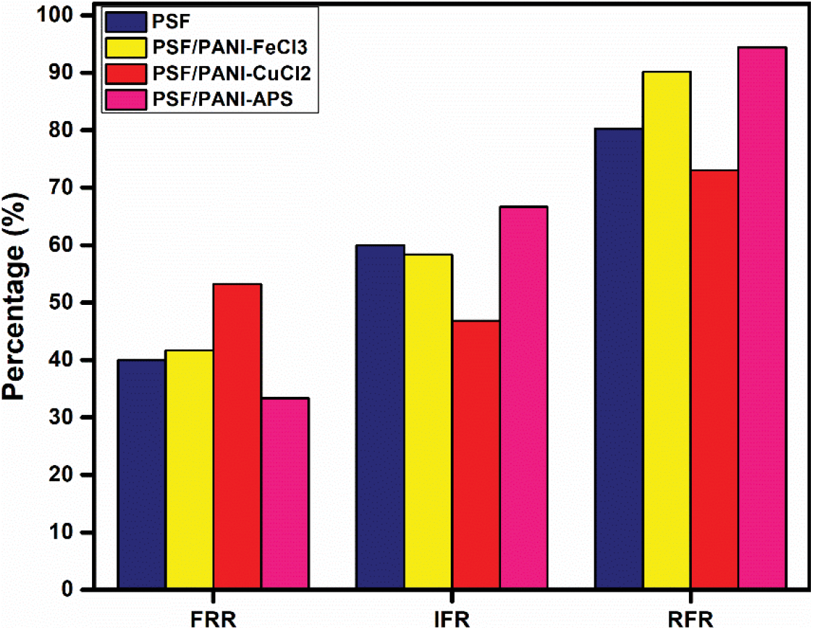
Figure 14. Anti-fouling performance of (a) PSF, (b) PSF/PANI-FeCl3, (c) PSF/PANI-CuCl2,and (d) PSF/PANI-APS membranes.
The properties of pure polysulfone membranes are successfully modified by incorporating polyaniline; using different oxidants, on the surface of the membrane. Characterization and experimental results confirm that the hydrophilicity of the membrane surface is significantly improved with the addition of polyaniline. Larger pore size and enhanced surface roughness provide the basis for higher values of pure water flux for PSF/PANI-FeCl3 and PSF/PANI-CuCl2 membranes with improved rejection ability. While in the case of the PSF/PANI-APS membrane, a decreased average pore size and comparatively denser layer is obtained which contributes to the deteriorated performance of the membrane. Despite improved wettability (lower contact angle), PSF/PANI-APS membrane exhibits lower pure water flux and poor permeate flux for protein filtration. Superior permeability, hydrophilicity, rejection, and fouling-resisting ability most encouraging results are recorded for PSF/PANI-CuCl2 membrane. The conclusion drawn with the present study can be illustrated as, incorporating polyaniline via in-situ surface-initiated polymerization; using oxidants having metal ions, provides better distribution of porous layer on pure polysulfone membrane and thus show better membrane performance in comparison to membrane modified by polyaniline via using APS as an oxidant.
Acknowledgement: The authors deeply value the financial support provided by the Guru Gobind Singh Indraprastha University, Delhi, India (IPRF No. GGSIPU/DRC/Ph.D./Adm./2017/253 and GGSIPU/DRC/FRGS/2019/1553/43).
Conflict of interest: There are no relevant financial or non-financial competing interests to report.
References
1. L Gao, K Su, T Fan, Z Li, Polymer, 176 (2019): 274. [Google Scholar]
2. C Kahrs, J Schwellenbach, Polymer, 186(2020): 122071. [Google Scholar]
3. ST Kassa, CC Hu, YC Liao, JK Chen, JP Chu, Surface and Coatings Technology, 368(2019): 33. [Google Scholar]
4. M. Arjmandi, M. Pourafshari Chenar, M. Peyravi, & M. Jahanshahi, Journal of Applied Polymer Science, 137(2020): 48672. [Google Scholar]
5. S. Muchtar, M.Y. Wahab, L.F. Fang, S. Jeon, S. Rajabzadeh, R. Takagi, S. Mulyati, N. Arahman, M. Riza & H. Matsuyama, Journal of Applied Polymer Science, 136(2019): 47312. [Google Scholar]
6. X. Huang, B. T. McVerry, C. Marambio-Jones, M. C. Wong, E. M. Hoek & R. B.Kaner, Journal of Materials Chemistry A, 3(2015): 8725. [Google Scholar]
7. R. Mukherjee, R. Sharma, P. Saini & S. De, Environmental Science: Water Research & Technology, 1(2015): 893. [Google Scholar]
8. L. Eykens, K. De Sitter, L. Stoops, C. Dotremont, L. Pinoy, & B. Van der Bruggen, Journal of Applied Polymer Science, 134(2017): 45516. [Google Scholar]
9. M. A. Imran, G. He, X. Wu, X. Yan, T. Li & A. S. Khan, Journal of Applied Polymer Science, 136(2019): 47892. [Google Scholar]
10. N. K. Saha, M. Balakrishnan & M. Ulbricht, Journal of Membrane Science, 306 (2007): 287. [Google Scholar]
11. H Susanto, H. Arafat, E. M. Janssen & M. Ulbricht, Separation and Purification Technology, 63(2008): 558. [Google Scholar]
12. L. Palacio, C. C. Ho, P. Prádanos, A. Hernández & A. L. Zydney, Journal of Membrane Science, 222(2003): 41. [Google Scholar]
13. C. C. Ho & A. L. Zydney, Journal of colloid and interface science, 232(2000): 389. [Google Scholar]
14. N. K.Saha, M. Balakrishnan & M. Ulbricht, Desalination, 189(2006): 59. [Google Scholar]
15. A. Xie, J. Cui, Y. Chen, J. Lang, C. Li, Y. Yan, & J. Dai, Surface and Coatings Technology, 361(2019): 19. [Google Scholar]
16. Z. Wei, J. Gu, Y. Ye, M. Fang, J. Lang, D. Yang & Z. Pan, Surface and Coatings Technology, 381(2020): 125147. [Google Scholar]
17. E.Velayi, & R. Norouzbeigi, Surface and Coatings Technology, 385(2020): 125394. [Google Scholar]
18. Y. Q. Song, J. Sheng, M. Wei & X. B. Yuan, Journal of applied polymer science, 78(2000): 979. [Google Scholar]
19. S. Gupta, D. Bhatiya, C. N. Murthy, Separation Science and Technology, 50(2015): 421. [Google Scholar]
20. M. Saxena, S.G. Chaudhri, A.K. Das, P.S. Singh, A. Bhattacharya, Separation Science and Technology, 54(2019): 343. [Google Scholar]
21. T. Wu, Y. Liu, G. D. Zhu, Z. N. Li, Z. Yi, L. F. Liu, & C. J. Gao, Polymer, 185(2019): 121949. [Google Scholar]
22. L. P. Zhu, J. Z. Yu, Y. Y. Xu, Z. Y. Xi, & B. K. Zhu, Colloids and Surfaces B: Biointerfaces, 69(2009): 152. [Google Scholar]
23. J. M. D'Arcy, H. D. Tran, V. C. Tung, A. K. Tucker-Schwartz, R. P. Wong, Y. Yang, & R. B.Kaner, Proceedings of the National Academy of Sciences, 107(2010): 19673. [Google Scholar]
24. J. Peng, Y. Su, Q. Shi, W. Chen & Z. Jiang, Bioresource Technology, 102(2011): 2289. [Google Scholar]
25. S. X. Liu & J. T. Kim, Journal of adhesion science and technology, 25(2011): 193. [Google Scholar]
26. M. Sun, Y. Su, C. Mu & Z. Jiang, Industrial & Engineering Chemistry Research, 49(2010): 790. [Google Scholar]
27. H. H. Rana, N. K.Saha, S. K. Jewrajka & A. V. R. Reddy, Desalination, 357(2015): 93. [Google Scholar]
28. S. Zhao, Z. Wang, J. Wang & S. Wang, Industrial & Engineering Chemistry Research, 53(2014): 11468. [Google Scholar]
29. S. Zhao, Z. Wang, X. Wei, B. Zhao, J. Wang, S. Yang & S. Wang, Industrial & engineering chemistry research, 51(2012): 4661. [Google Scholar]
30. H. Shi, Y. He, Y. Pan, H. Di, G. Zeng, L. Zhang & C. Zhang, Journal of Membrane Science, 506(2016): 60. [Google Scholar]
31. Z. Fan, Z. Wang, N. Sun, J. Wan & S. Wang, Journal of Membrane Science, 320(2008): 363. [Google Scholar]
32. Z. Fan, Z. Wang, M. Duan, J. Wang & S. Wang, Journal of Membrane Science, 310(2008): 402. [Google Scholar]
33. J. Chen, J. Li, Z. P. Zhao, D. Wang & C. X. Chen, Surface and Coatings Technology, 201(2007): 6789. [Google Scholar]
34. T. Chittrakarn, Y. Tirawanichakul, S. Sirijarukul & C. Yuenyao, Surface and Coatings Technology, 296 (2016): 157. [Google Scholar]
35. D. S. Wavhal & E. R. Fisher, Desalination, 172(2005): 189. [Google Scholar]
36. T. Hasegawa, Y. Iwasaki & K. Ishihara, Biomaterials, 22 (2001): 243. [Google Scholar]
37. B. T. McVerry, J. A. Temple, X. Huang, K. L. Marsh, E. M. Hoek & R. B. Kaner, Chemistry of Materials,25(2013): 3597. [Google Scholar]
38. M. Liu, J. Li & Z. Guo, Journal of colloid and interface science, 467(2016): 261. [Google Scholar]
39. Z. Zhang, J. Deng & M. Wan, Materials Chemistry and Physics, 115(2009): 275. [Google Scholar]
40. L. Zhang, M. Wan & Y. Wei, Macromolecular rapid communications, 27(2006): 366. [Google Scholar]
41. A. Pant, R. Tanwar, B. Kaur & U. K. Mandal, Scientific Reports, 8(2018): 1. [Google Scholar]
42. U. Bogdanovi, V. V. Vodnik, S. P. Ahrenkiel, M. Stoiljkovi, GiriMarjanovi & J. M. Nedeljkovi, Synthetic metals, 195(2014): 122. [Google Scholar]
43. U. Bogdanovic, V. Vodnik, M. Mitric, S. Dimitrijevic, S.D. Skapin, V. Zunic, M. Budimir & M. Stoiljkovic, ACS applied materials & interfaces, 7(2015): 1955. [Google Scholar]
44. U. Bogdanovic, I. Pasti, G. Ciric-Marjanovic, M. Mitric, S. P. Ahrenkiel & V. Vodnik, ACS Applied Materials & Interfaces, 7(2015): 28393. [Google Scholar]
45. S. H. Piao, M. Bhaumik, A. Maity & H. J. Choi, Journal of Materials Chemistry C, 3(2015): 1861. [Google Scholar]
46. P. Dallas, D. Stamopoulos, N. Boukos, V. Tzitzios, D. Niarchos & D. Petridis, Polymer, 48(2007): 3162. [Google Scholar]
47. S. B. Teli, S. Molina, A. Sotto, E. G. Calvo & J. D. Abajob, Industrial & Engineering Chemistry Research, 52(2013): 9470. [Google Scholar]
48. G. R. Guillen, T. P. Farrell, R. B. Kaner & E. M. Hoek, Journal of Materials Chemistry, 20(2010): 4621. [Google Scholar]
49. P. Daraei, S. S. Madani, N. Ghaemi, E. Salehi, M. A., Khadivi, R. Moradian & B. Astinchap, Journal of Membrane Science, 415(2012): 250. [Google Scholar]
50. Y. Wei, X. Tang, Y. Sun & W. Focke, J. Polym. Sci., Part A: Polym. Chem. 27(1989): 2385. [Google Scholar]
51. N. Kumari Jangid, S. Jadoun, N. Kaur, Eur. Polym. J. 125(2020): 109485. [Google Scholar]
52. D. Ficai, A. Ficai, G. Voicu, B. S. Vasile, C. Guran & E. Andronescu, Matr Plastice, 47(2010): 24. [Google Scholar]
53. A. L. inares & J. L. Acosta, Journal of applied polymer science, 92(2004): 3030. [Google Scholar]
54. E. T. Kang, K. G. Neoh & K. L. Tan, Progress in polymer science, 23(1998): 277. [Google Scholar]
55. G. Han, S. Zhang, X. Li, N. & Chung, T. S. Chemical Engineering Science, 80(2012): 219. [Google Scholar]
56. S. Tan, J. H. Tieu & D. Bélanger, The Journal of Physical Chemistry B, 109 (2005): 14085. [Google Scholar]
57. Y. Chen, E. T. Kang, K. G. Neoh, S. L. Lim, Z. H. Ma & K. L. Tan, Colloid and polymer Science, 279(2001): 73. [Google Scholar]
58. K. G. Neoh, E. T. Kang & K. L. Tan, The Journal of Physical Chemistry B, 101(1997): 726. [Google Scholar]
59. S. Tan, A. Laforgue & D. Bélanger, Langmuir, 19(2003): 744. [Google Scholar]
60. X. L. Wei, M. Fahlman & A. J. Epstein, Macromolecules, 32(1999): 3114. [Google Scholar]
61. S. H. Goh, S. Y. Lee, X. Zhou & K. L. Tan, Macromolecules, 31(1998): 4260. [Google Scholar]
62. Y. T. Chung, E. Mahmoudi, A. W. Mohammad, A. Benamor, D. Johnso & N. Hilal, Desalination, 402(2017): 123. [Google Scholar]
63. V. Goel & U. K. Mandal, Korean Journal of Chemical Engineering, 36(2019): 573. [Google Scholar]
64. V. Goel, R. Tanwar & U. K. Mandal, Journal of Chemical Technology & Biotechnology, 96(2021): 502. [Google Scholar]
65. R. N. Wenzel, Industrial & Engineering Chemistry, 28(1936): 988. [Google Scholar]
66. D. Rana & T. Matsuura, Chemical reviews, 110(2010): 2448. [Google Scholar]
67. M. Hirose, H. Ito & Y. Kamiyama, Journal of Membrane Science, 121 (1996): 209. [Google Scholar]
68. L. Yan, Y. S. Li, C. B. Xiang & S. Xianda, Journal of Membrane Science, 276(2006): 162. [Google Scholar]
69. E. M. Vrijenhoek, S. Hong & M. Elimelech, Journal of Membrane Science, 188(2001): 115. [Google Scholar]
70. I. H. Huisman, P. Prádanos & A. Hernández, Journal of Membrane Science, 179(2000): 79. [Google Scholar]
Cite This Article
 Copyright © 2022 The Author(s). Published by Tech Science Press.
This work is licensed under a Creative Commons Attribution 4.0 International License , which permits unrestricted use, distribution, and reproduction in any medium, provided the original work is properly cited.


 Submit a Paper
 Propose a Special lssue
 View Full Text
 Download PDF
 Downloads
 Citation Tools