 Open Access
ARTICLE
Preparation of Polysulfone Capillary Ultrafiltration Membranes for Pre-treatment of Sea Water Reverse Osmosis and Studies on its Fouling behavior after Turbidity Removal from Sea Water
Membrane Development Section, Chemical Engineering Group, Bhabha Atomic Research Centre, Trombay, Mumbai, India.
* Corresponding Author: e-mail:
Journal of Polymer Materials 2022, 39(1-2), 137-149. https://doi.org/10.32381/JPM.2022.39.1-2.9
Abstract
In this study, polysulfone based capillary ultrafiltration membranes with desired characteristics were indigenously developed and their performance was evaluated with respect to turbidity removal from raw sea water. Capillary membranes were spun with in-house fabricated spinneret using polymer casting solution (dope solution) of different compositions having different viscosity using polyvinyl pyrrolidone (PVP) as pore-forming agent. Different experimental conditions namely dope pressure, bore fluid flow rate and air gap distance are optimized to get membranes of desired properties. Test results of individual capillaries in terms of pure water permeability (PWP), separation of single uncharged solutes like polyethylene glycol (PEG) and mechanical strength were discussed. Increase in dope pressure and air gap decreases PWP but increases the strength of the capillary membranes whereas addition of PVP in dope solution and increase in bore fluid flow rate has opposite effect on PWP and strength of the membrane. The optimum range of dope feed pressure was found 1-1.25 kg/cm2 with bore fluid flow rate of 25-30 ml/min and air gap of 12-15 cm. Selected membranes were tested for removal of turbidity from raw sea water with turbidity upto 120 NTU and the extent of turbidity removal was studied as a function of turbidity loading of sea water. The membranes were able to remove turbidity by more than 97.5%. After sea water filtration, the pure water flux recovery was evaluated on cleaning by backwashing using DI water.Keywords
In last few decades, membranes have gained wide acceptance and made significant in roads against competing technologies in many areas because of flexibility and performance reliability of membrane system, cost competitiveness, increasing demand and environmental awareness[1]. One such application of membrane is pre-treatment of sea water reverse osmosis in place of conventional treatment process consists coagulation, flocculation, sedimentation, and media filtration. Recent years, ultrafiltration (UF) membranes are used as pretreatment to reverse osmosis process as it is a simple, easy to use and robust alternative to conventional treatments which is known to be complex, labour intensive and space consuming[2]. The benefits of UF pretreatment of feed sea water in terms of capital investment cost and operating cost for affective and cost-effective desalination is discussed in literature[3]. However, UF membranes are found to fouled with time and the extent of fouling depends on membranes morphology with its chemical nature, the membrane assembling configuration and also the operating conditions like the pressure difference across the membrane during filtration, the cross-flow velocity, the hydraulic retention time etc. To predict and prevent membrane fouling in UF process, the understanding on the effect of various factors influenced membrane fouling is essential. Very recently, a comprehensive review was published on mechanism, impact, and control of membrane fouling[4].
Regarding membranes morphology and the chemical nature of membrane materials, commonly used UF membranes are mainly categorized into organic polymeric membranes, inorganic ceramic membranes, metal membranes and most of these are prepared in asymmetric form. The most widely used are from organic polymeric membranes including polypropylene (PP), polysulfone (PSf), polyethersulfone (PES), polyacrylonitrile (PAN) and polyvinylidene fluoride (PVDF)[5]. Even though various combinations of blended and nanocomposite membranes were studied[6-8] but in actual practice, PSf and PES based UF membranes are mostly used in sea water pre- treatment[9]. Due to the balanced hydrophilic- hydrophobic properties, PSf membrane not only wets out quickly and results in fast filtration with better flow rates but also has less fouling tendency than some of the common polymeric membranes. Fouling of UF membranes on filtration of raw sea water and fouling by other organic foulants has been studied and reported in the literatures[10-15]. Regarding membrane assembly configurations, UF membranes are used in spiral-wound, tubular and capillary/hollow fibre modules. The extremely high packing density and special design of channels conferred the capillary/hollow fiber membrane module excellent mass-transfer properties and higher water permeability suitable for numerous commercial applications. The other important characteristics of capillary based modules which make it more favorable than all other membrane assembly configurations are its lowest energy consumption, operation at relatively high liquid velocity in laminar flow mode, having very high shear rates at the membrane surface which reduces susceptibility to fouling, self-supporting structure for better backwashing than fabric supported sheet membranes, flexibility in operation by using it in ‘inside-out’, ‘outside-in’ or ‘dead-end’ mode[16]. With respect to better control of flow and more uniform flow distribution, an inside-out mode of operation is preferable than an outside-in flow. However, for sea water pre-treatment, capillary/ hollow fibre based UF membranes are used mostly outside-in flow configuration[17-20]. Typically, the internal diameter of the membrane fibres used is in the range of 0.4 to 1.5 mm[21].
In membrane-based pre-treatment, polysulfone or polyethersulfone capillary UF back-washable elements are used in both dead-end and cross- flow mode in most of the practical cases. Fouling is controlled by proper pre-treatment of the feed sea water and later backwashing in regular interval during operation. However, very few selected varieties of UF membranes having defined pore sizes and surface characteristics are available commercially which cannot give complete ideas on how fouling of membrane by sea water is influenced by membrane properties.
So, objective of the present study, is to prepare capillary membranes with different properties like pore size, porosity, mechanical strength, etc. Capillary membranes were spun by changing spinning parameters namely, polymer casting solution (called dope) composition, dope pressure during spinning, bore fluid flow rate, air gap between the spinneret and water bath etc. in order to get UF membranes with varied porosity, pore sizes and mechanical strengths. Capillary membranes (1 to 2 mm dia) and modules are developed by aiming at reducing energy requirements for ultrafiltration for turbidity reduction and can be used in pre-treatment of seawater.
Polysulfone (molecular weight = 50-60 KDa, Solvay make), N-methyl pyrrolidone (NMP; 99.0% pure, Sigma- Aldrich make), Polyvinyl pyrrolidone (PVP; molecular weight = 40KDa, Sisco Research Laboratory, SRL weight = 40KDa, Sisco Research Laboratory, SRL make), polyethylene glycol (PEG; molecular weight = 100 KDa and 300 KDa; make: SRL make), glycerol (Sisco Research Laboratory make) is used directly without further purification. Feed sea water/backwater available from Trombay Jetty, BARC, Mumbai was used for turbidity removal studies.
The casting solutions (dope) were prepared using PSf, PVP and NMP at different compositions as given in Table 1. The dope solution was pressurized under Nitrogen pressure of 0.75 kg/cm2, 1.00 kg/cm2, 1.25 kg/cm2 and 1.50 kg/cm2 above atmospheric pressure along the annular gap in the spinneret for different sets of experiments. The bore fluid which is UF treated water was pumped through the axial bore of spinneret using peristaltic metering pump with bore fluid flow rate of 20ml/min, 25ml/min, 30ml/min and 35ml/min. The polymer dope solution and the non-solvent water mixes at the outlet of spinneret (outer diameter = 2 mm and inner diameter = 1 mm) causing non solvent induced phase inversion and capillary membrane formation. The nascent capillary fibre coming out from the spinnerets is passed into water bath (external coagulant) where solvent is exchanged with water and the polymer precipitates out as membrane. The air gap maintained between the spinneret and water bath was 9 cm., 12 cm., 15 cm. and 18 cm. respectively for different sets of experiments. During the membrane preparation, dope was used at ambient temperature in the range of 24-26°C; humidity was in the range 45-51%; bore fluid and external coagulant was UF filtered water. The air gap between spinneret and external coagulant bath was maintained in the range of 10-12 cms. The membrane thus obtained were treated with UF filtered water to remove solvent and subsequently treated with 10% v/ v glycerol solution for 24 hours and then air dried for 24 hours before carrying out further evaluation of membrane properties.

Characterizations of the capillary membranes
Screw gauge was used to obtain capillary membrane outer diameter (OD) and thickness (t) to obtain inner diameter (ID). Universal testing machine (Instron 5540 Series Single Column Testing Systems; Instron, Norwood, Massachusetts, USA) was used to obtain tensile strength (TS) of the fibres by following ASTM D638 M standards for polymers. Electron microscopic (SEM) images of the capillary membranes were taken using SEM machine (Model: CamScan3200LV) after making the membrane samples electrically conductive by coating the surface with gold-palladium using sputter coater. Total organic carbon (TOC) Analyser instrument (make: ANATOC) was used to obtain organic carbon concentration to evaluate % rejection of PEG. Turbidity meter (make: Hanna Instruments) was used to find the turbidity of feed seawater and permeate water in terms of Nephlometric Turbidity Unit (NTU).
Performance evaluation and fouling studies of the membranes
Pure water permeability (PWP) & Solute Rejection studies: Electro de-ionized water was pressurized at 1kg/cm2 to the PSf capillary membranes to obtain PWP and expressed in the unit- liter/(square meter, hour) (lmh). PEG of molecular weight 100 KDa and 300 KDa were used to study solute rejection of PSf capillary membrane by preparing PEG solute solution of 200 ppm in UF filtered water which was pressurized at 1kg/cm2 to the PSf capillary membranes. The feed and permeate water were analyzed to obtain % solute rejection using TOC analyser.
Turbidity Removal studies: Turbidity removal of feed seawater, availed from in-house desalination plant, was used as feed and pumped at 1 kg/cm2 to the PSf UF capillary membrane module (1" dia. and 10" long) consisting of 15 numbers of PSf capillary fibers (7" active length). The turbidity of feed and product water was obtained using Turbidity meter.
Fouling Studies: Fouling studies was carried out using seawater as feed to PSf capillary membrane module with same effective area. The operation was carried out in cross-flow condition and in recirculation mode using 50 liters of batch solution. At first, deionized (DI) water is passed through the membrane at 4 Bar pressure until the flux remained constant over more than 30 mins. The end of the stabilization period is taken as the zero-time point in the filtration plots. Then the raw sea water is passed in all the membranes. Sample of permeate is collected in regular interval of filtration operation. After 8-10 hrs. of operation, DI water is used as a feed to determine the reversibility of fouling. Fouling studies are carried out at constant initial flux (25 lmh) for proper comparison of fouling tendency on change in type of the membrane.
Both the surface and bulk properties of capillary membranes varied on variation of spinning parameters. The dope feed pressure, air gap and bore fluid flow rate were varied and its effect on membrane performance in terms of water permeation rate as well as the mechanical strength were evaluated. Single uncharged solute, PEG rejection data is an indication of relative pore sizes i.e. higher rejection corresponds to smaller pore sizes and vice-versa. SEM images indicate the homogeneity in pores formation without defects. Turbidity removal and fouling studies were also carried out.
SEM analysis of the capillary membrane
The membranes structure for the membrane prepared with dope composition S4 at dope feed pressure of 1 kg/cm2, bore fluid flow rate of 25 ml/min and air gap of 25 cm, was visualized using SEM (Figure 1). It was found that the membranes have an asymmetric structure with the thin selective layer both at the inside and outside of membrane whereas highly porous finger like macro-voids are present in between.
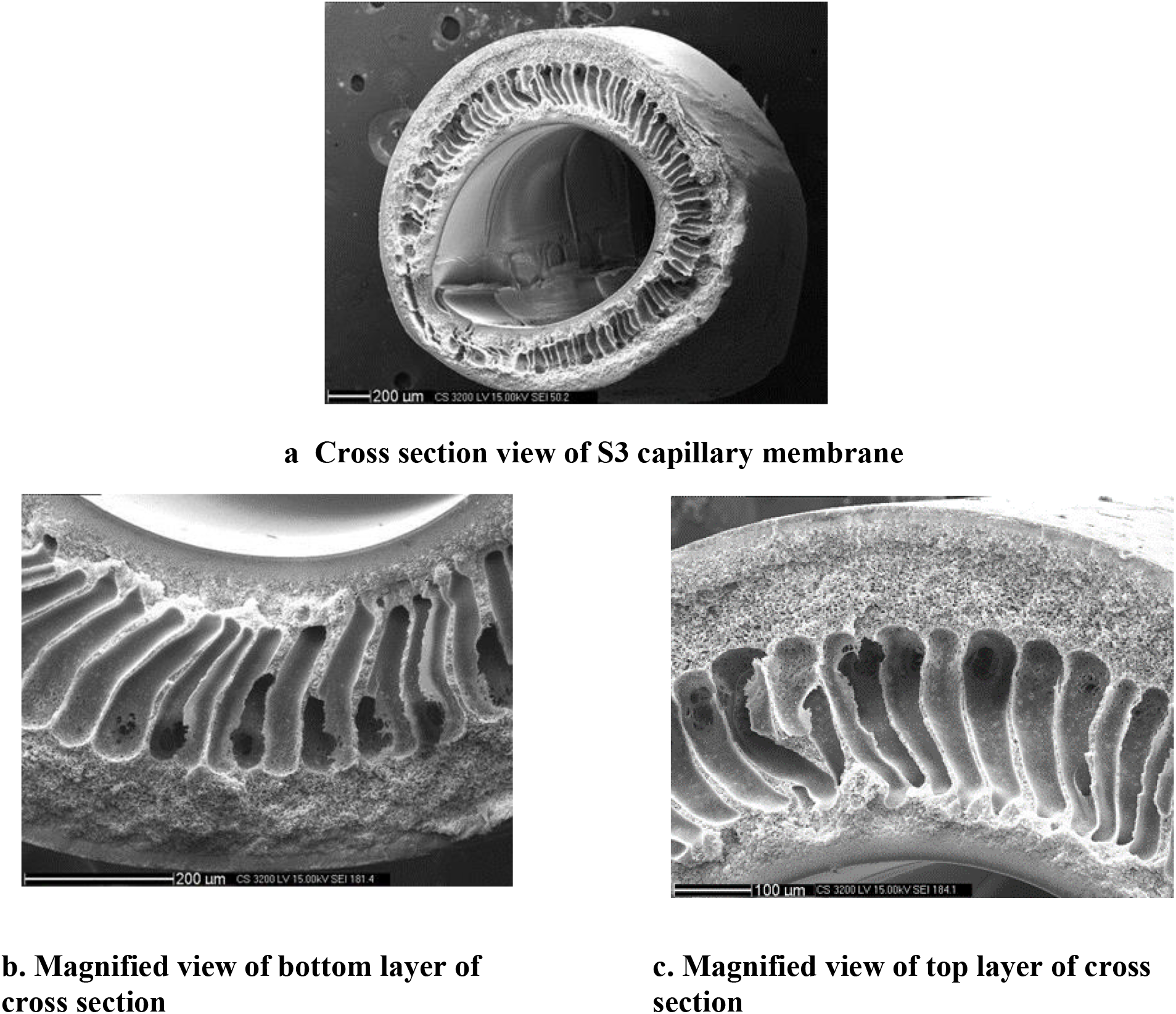
Figure 1.: SEM images of capillary membranes from formulation S4
The outer and inner thin selective layer may be attributed to the immediate sliding of the polymer at the outer and inner surface that reduces the rate of leaching of solvent (NMP) and subsequent filling up of pores by the non-solvent (water) is slow leading to thick inner and outer surface. The finger like macro-void structure may have been formed due to strong non-solvent in the bore fluid and coagulation bath that promotes aggressive exchange between the solvent and non-solvent.
Effect of PVP on performance and mechanical strength of the capillary membranes
In general, PVP acts as a pore former. With increase in concentration of PVP, the large pores are formed. Further the migration of PVP, due to its hydrophilic property leads to the merger of pores and further increasing in pore size. Low concentration of PVP increases the rate of phase inversion process wherein outer and inner skin solidifies quickly leading to small pores. High concentration of PVP increases the viscosity of the dope solution which slows down the phase inversion process. During the solidification process of the membrane, high viscosity hinders the movement of PVP and solvent out from the dope solution into the bore fluid during dry phase inversion. Membrane starts to solidify, PVP and solvent leached out from the membrane at slower rate. This increases the number of pores and the pore size, thus increasing PWP, decrease in solute rejection. The increase in pore size decreases strength of the fiber. Thus, PWP and % solute rejection decreases from samples S1 to S4 while tensile strength increases from samples S1 to S4.
Effect of Dope Pressure on performance & mechanical strength of capillary membranes
The dope pressure was varied from 0.75 kg/ cm2 to 1.50 kg/cm2 as shown Figures 2 & 3, to obtain PWP & TS of the PSf capillary membrane fiber. The air gap of 12 cm was maintained between spinneret and water bath and bore fluid flow rate was maintained at 25 ml/min.
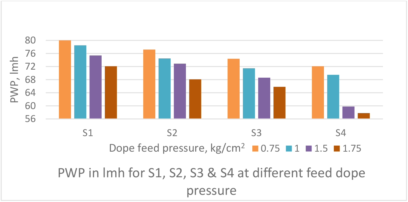
Figure 2.: Effect of dope feed pressure on PWP of PSf capillary membranes
The PWP decreases with increase in dope feed pressure (Figure 2). The TS increases with increase in dope feed pressure (Figure 3). It may be attributed to increase in shear forces in the annular orifice. It is known that polymer molecules under shear flow tend to align themselves in the direction of flow. This increases molecular orientation and thus the strength.
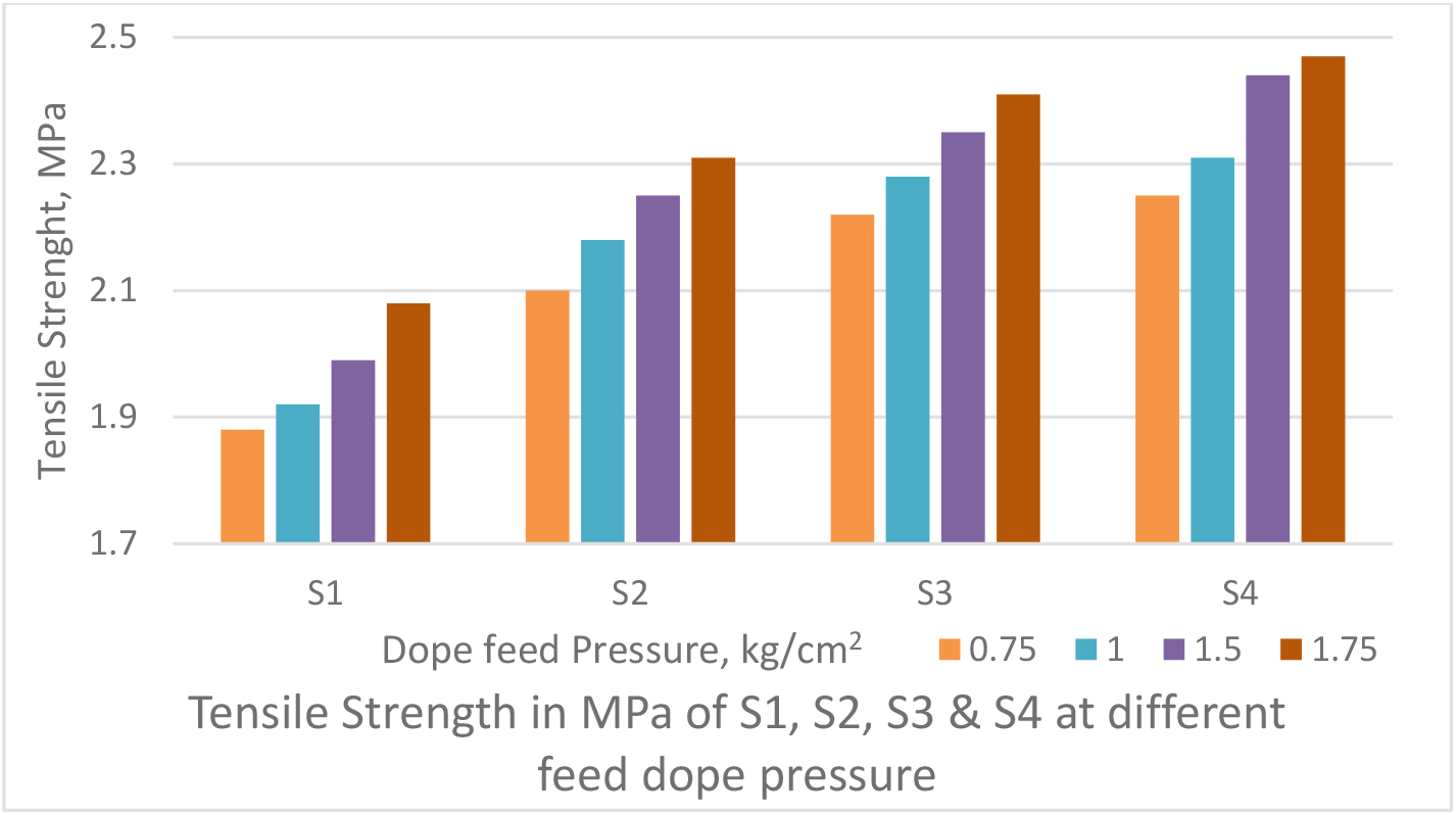
Figure 3.: Effect of dope feed pressure on Tensile Strength of PSf capillary membranes
Since the internal wall of the fibre precipitates immediately upon contact with the coagulant after emerging from the spinneret, the alignment of polymer chains freezes in place in the solid skin. As a consequence, the pores in the skin (which control retention and permeability) will be elongated. If the kinetics of gelation remains unchanged, rectangular pores of the same area as circular pores will show retention for smaller molecules and a lower permeability. Thus, increase in dope pressure decreases PWP whereas increases the strength of fibre.
It is observed that PWP decreased from S1 to S4. That is addition of PVP in the dope solution increased pure water permeability. The increase PWP is sharp when no PVP is present (S4) to 9.91% PVP concentration (S3) which increases PWP by 14.1% to 15.5%. While further increasing the concentration of PVP in dope solution from 9.91% (S3) to 17.1% (S1) increases PWP by 7.6% to 9.8%, suggesting optimum range of PVP from 0- 9.91% in dope solution.
Effect of air gap on performance and mechanical strength of the capillary membranes
The air gap between spinneret and water bath was varied from 9 cm to 18 cm as shown Figures 4 & 5 to obtain PWP & TS of the PSf capillary membrane fibre. The dope feed pressure of 1 kg/cm2 was maintained between spinneret and water bath and bore fluid flow rate was maintained at 25 ml/min.
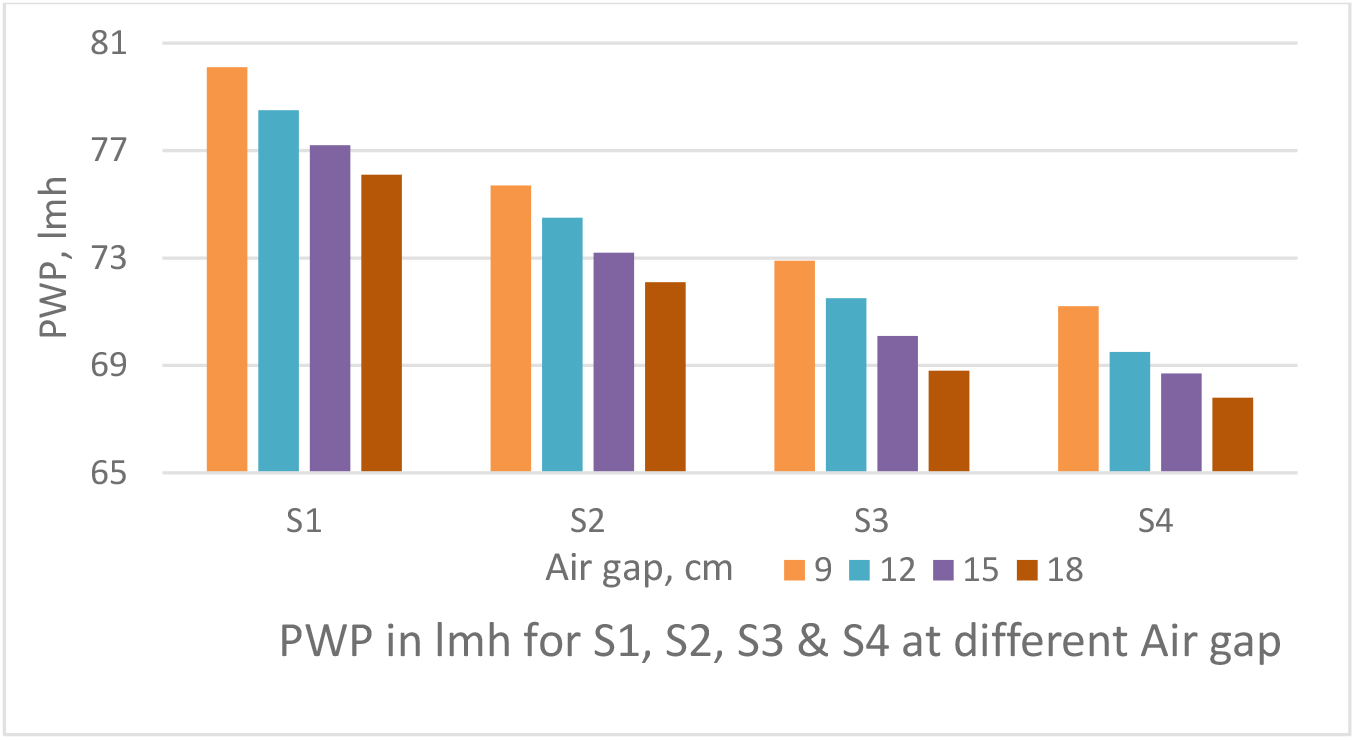
Figure 4.: Effect of air gap on PWP of PSf capillary membranes
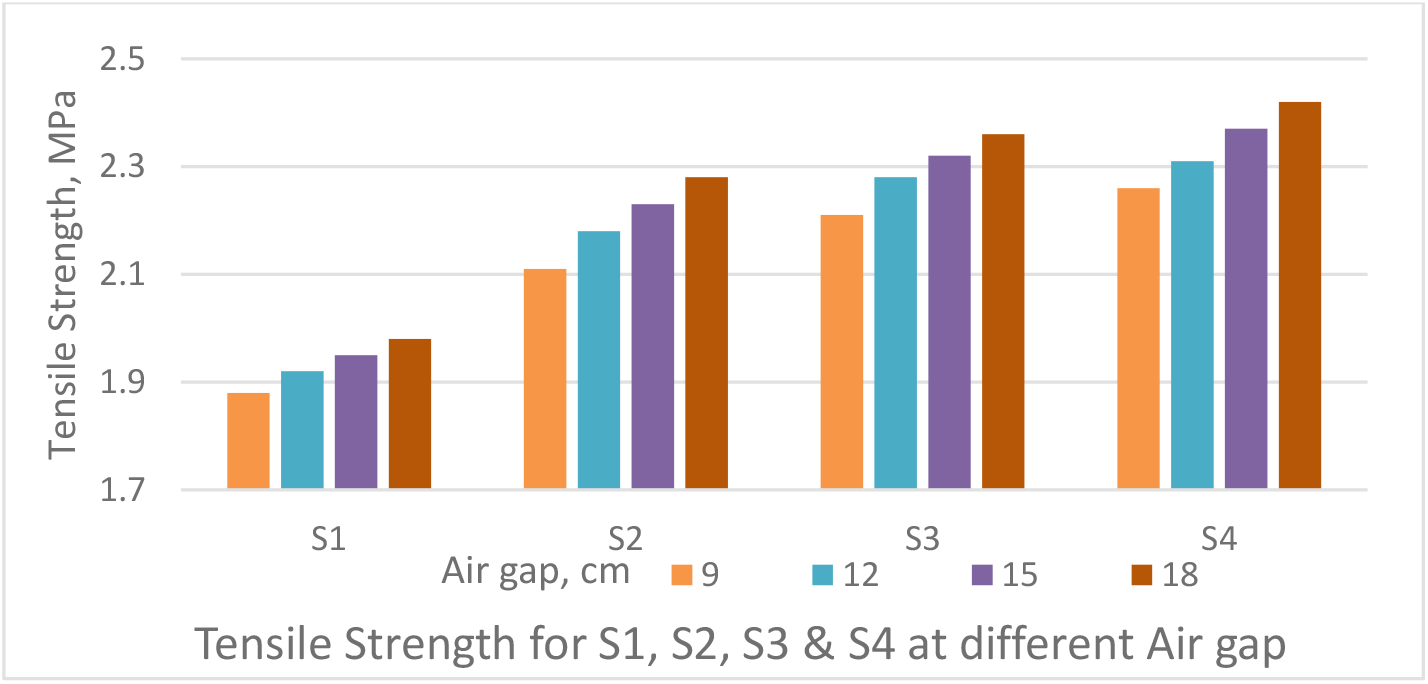
Figure 5.: Effect of air gap on Tensile Strength of PSf capillary membranes
The PWP decreases with increase in air gap as depicted in Figure 4. The TS increases with increase in air gap as shown in Figure 5. An increase in the air-gap, extends the polymer chains as they pass through the spinneret because of the added weight of the fibre below. Any tendency towards relaxation of the polymer chains after emerging from the spinneret and before gelation is alleviated by this weight tending to stretch, the fibre. Thus, an increase in the air-gap will only increase the degree of orientation resulting in tighter fibres. Thus, reducing the PWP and increasing the strength.
Effect of bore fluid flow rate performance and mechanical strength of the capillary membranes
The bore fluid flow rate was varied from 20 ml/ min to 35 ml/min as shown Figures 6 & 7, to obtain PWP & TS of the PSf capillary membrane fibre. The air gap of 12 cm was maintained between spinneret and water bath and dope feed pressure was maintained at 1 kg/cm2.
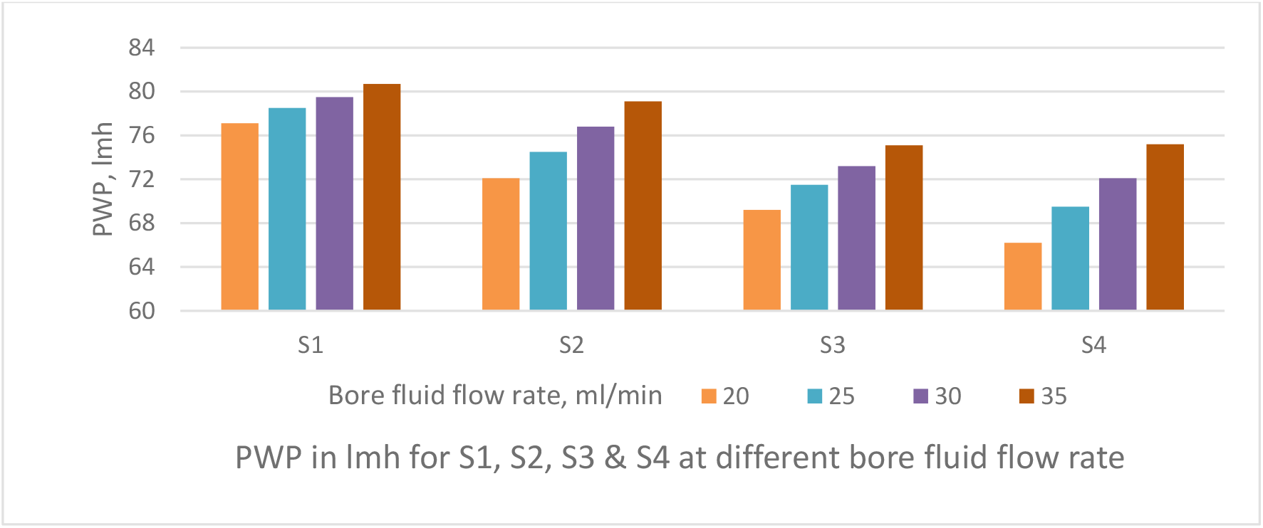
Figure 6.: Effect of bore fluid flow rate on pure water permeability of PSf capillary membranes
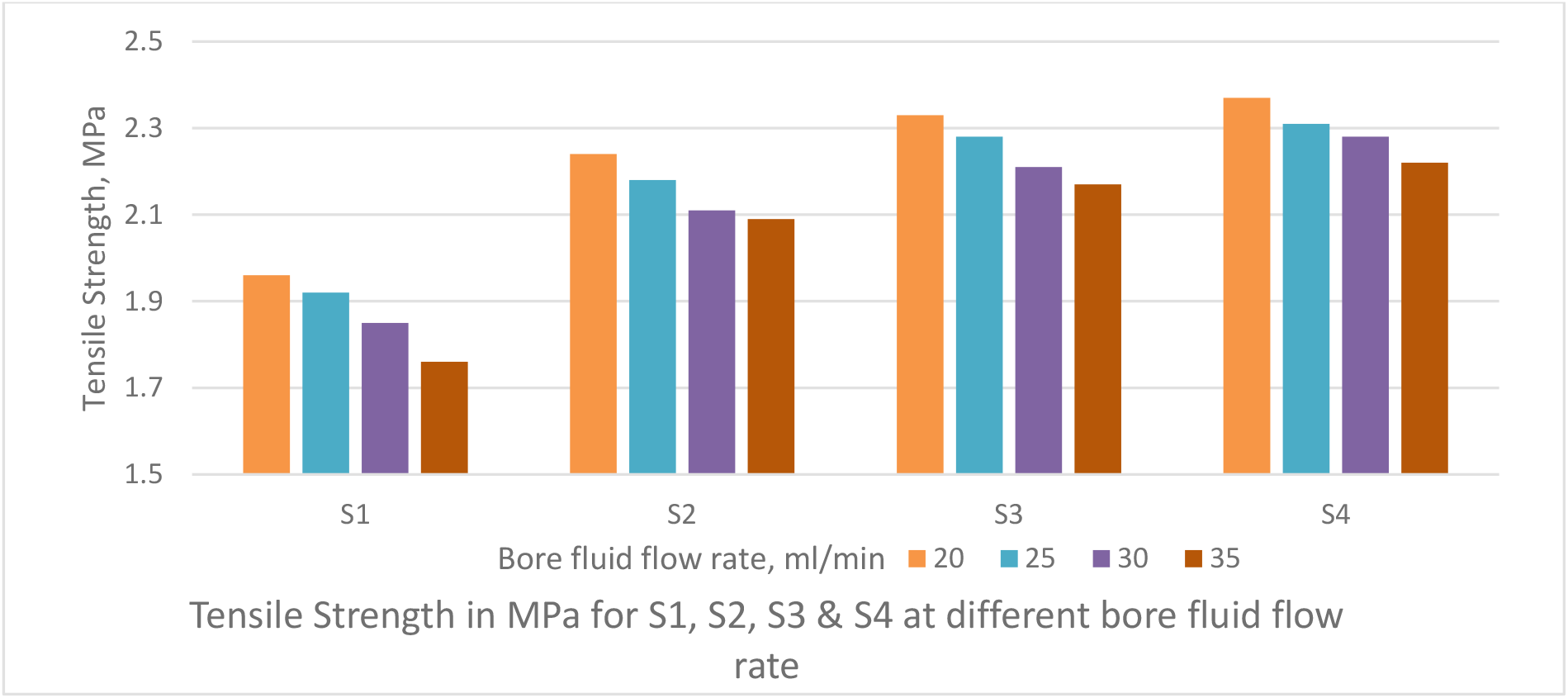
Figure 7.: Effect of bore fluid flow rate on Tensile Strength of PSf capillary membranes
The PWP decreases with increase in bore fluid flow rate as depicted in Figure 6. The TS increases with increase in bore fluid flow rate as shown in Figure 7. Bore fluid flow rate increase causes the coagulating fluid through the inner tube to counteract the elongation of pores in the skin; the increased pressure in the fiber lumen tends to expand its diameter and thereby enlarge the width of the elongated pores. The result is a more open fiber with increased permeability, decreased strength and decreased solute rejection. Figure 8 depicts the solute rejection of 100 KDa PEG, which decreases with increase in bore fluid flow rate and with increase in PVP concentration from S4 to S1 as pore size increases with bore fluid flow rate and PVP addition in dope solution.
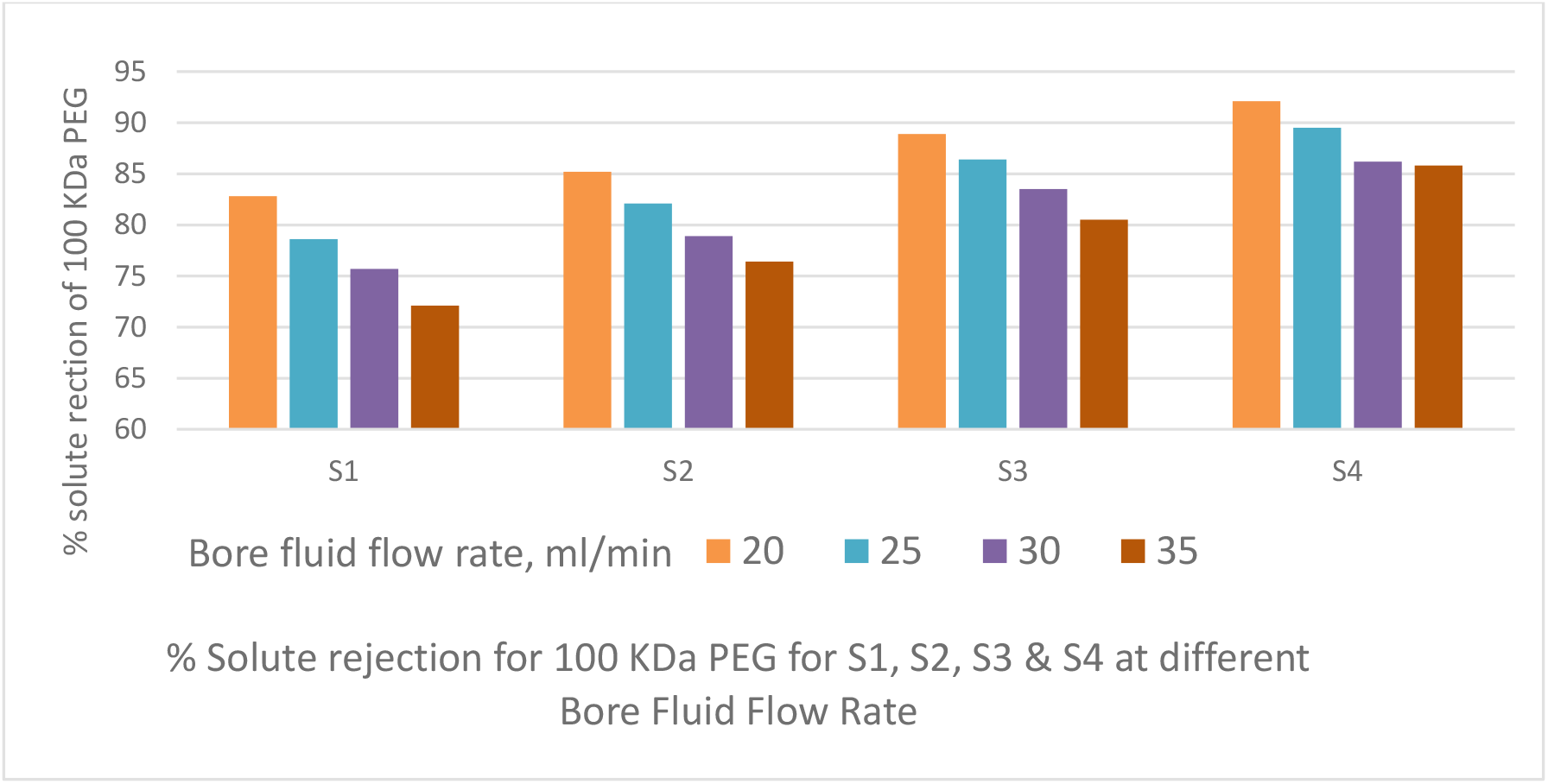
Figure 8.: Effect of bore fluid flow rate on % solute rejection of PEG 100 KDa by PSf capillary membranes
Turbidity Removal & Fouling Studies of the capillary membranes
PES capillary membrane fibers prepared using S3 & S4 dope compositions were used for turbidity removal of feed seawater and for fouling studies. The characteristics values (average of 5 random samples) of these PSf fibers are tabulated in Table 2. The percentage of turbidity removal as a function of feed turbidity of sea water is given in Figure 9. The turbid seawater with turbidity upto 120 NTU was treated and the product turbidity of less than 1.0 NTU was found by both the membranes with more than 97.5% turbidity removal. S4 membrane shows more turbidity removal than S3 which is in line with their solute rejection properties for single uncharged solutes, PEG.

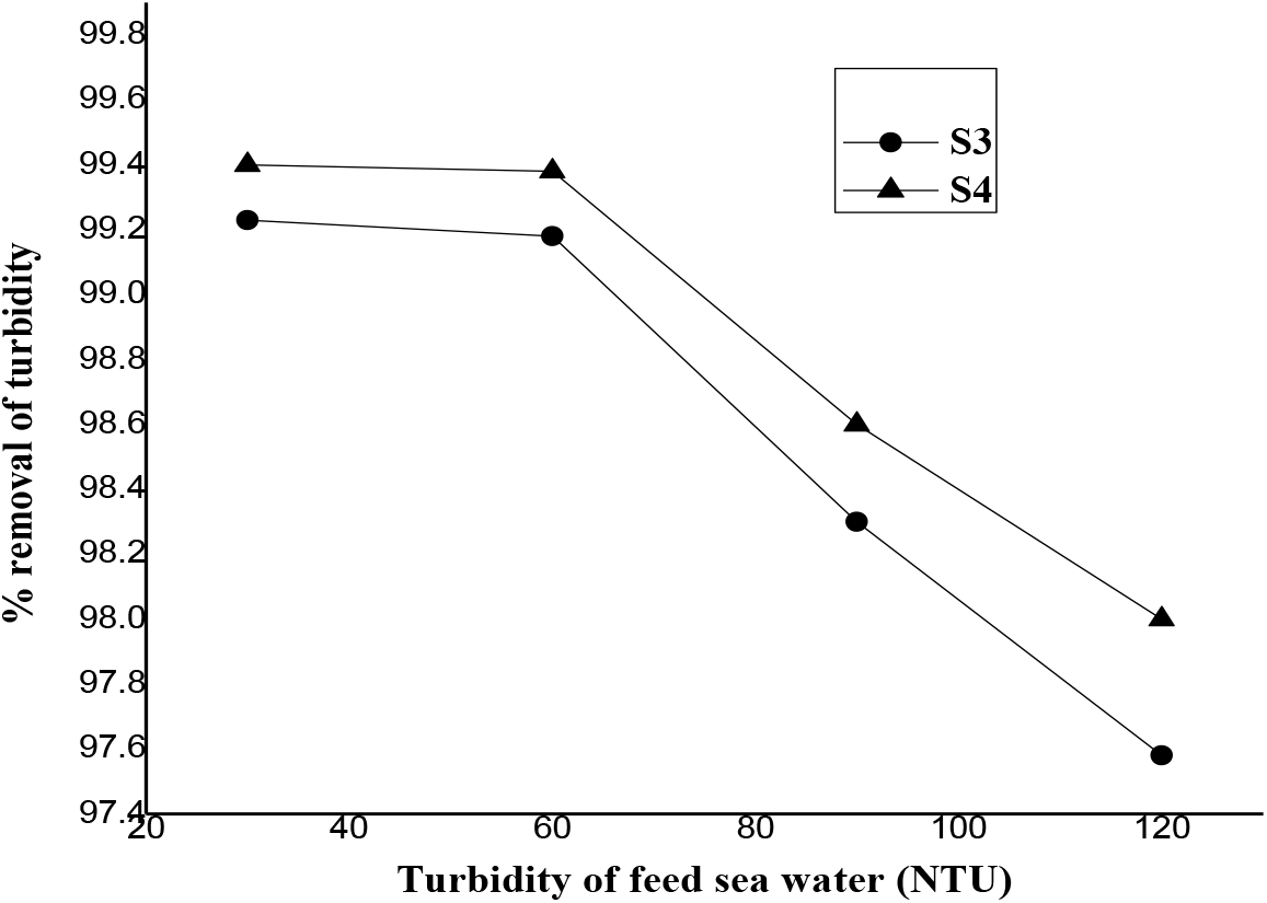
Figure 9.: Plot of the percentage of turbidity removal as a function of feed turbidity of sea water
Fouling studies was carried out with S3 & S4 based PSf capillary membrane fibers. The sea water fouling studies are carried out at initial flux of 25lmh for both the membranes. The plot of normalized flux (defined as ratio of instant flux to pure water flux at the end of the compaction i.e. 25 lmh) as a function of time of operation is given in Figure 10. In this case, the reversibility of fouling is determined by backwashing the fouled membranes in backward flow direction (permeate to feed side) using DI water as a feed at only 0.5kg/cm2 pressure. S4 capillary membranes with better solute rejecting properties shows slightly more flux decline (end constant flux on sea water permeation) than that of S3 membranes. This indicates that membranes with better solute rejection properties are more fouled than the relatively less solute rejecting ability. Better solute rejection can be consequences of either smaller sizes pores or formation of thicker gel layer by the foulants present in sea water.
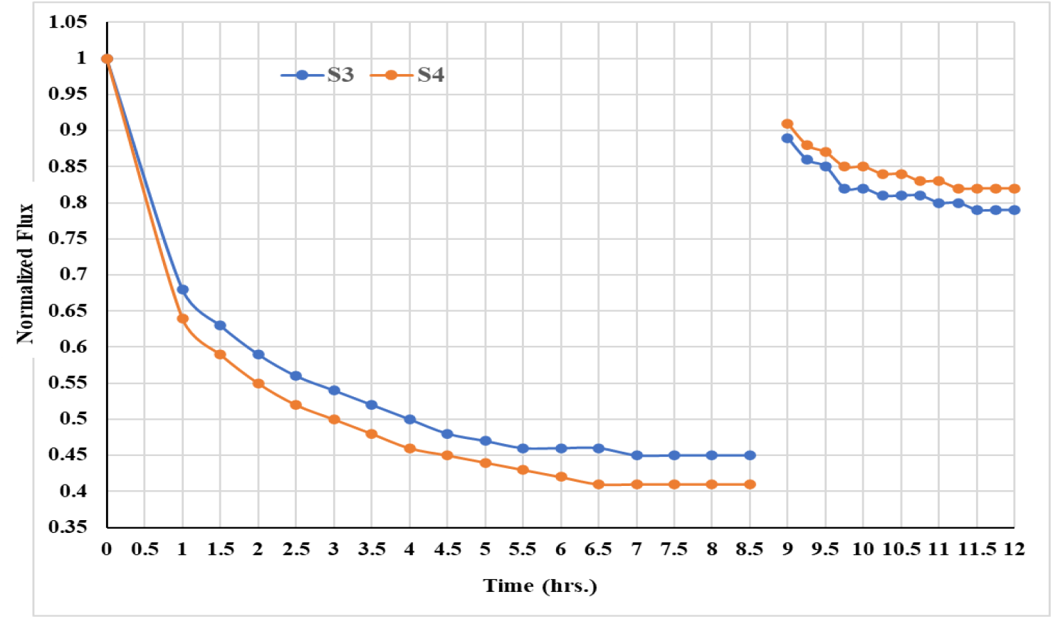
Figure 10.: Flux decline and recovery for capillary membranes on removal of turbidity from sea water
Interestingly, S4 membrane recovered 82.0% of its initial flux and S3 membranes recovered 79.0% of initial pure water flux after backwashing. This indicates that during filtration, more pores are blocked by the foulants results more flux decline with time which gets cleaned during the backwashing to give more flux recovery.
Polysulfone capillary membranes were tailor- made by varying dope composition (with and without additive), dope pressure, air gap, bore fluid flow rate. Capillary membranes prepared using additive (polyvinyl pyrrolidone) in the dope solution increases the pure water permeability due to increase of porosity of the membrane. The optimum range of capillary membrane preparation parameters such as dope feed pressure, bore fluid flow rate and air gap were found as 1–1.25 kg/cm2, 25–30 ml/min and 12-15 cm respectively to obtained membranes capable of giving pure water permeability of 68.7 to 79.5 liters.m-2.h-1 (LMH) with tensile strength in the range of 1.85 to 2.37 MPa. Increase in dope pressure and air gap results tighter membranes but the strength of the capillary membranes increases. Increase in concentration of additives in dope solution and increase of bore fluid flow rate results membranes with bigger pore size but the strength of the capillary membranes decreases. Polysulfone fibers prepared in-house with optimum performances were used to demonstrate the pre-treatment of sea water with turbidity upto 60 NTU to give product turbidity less than 1 NTU which is desired for desalination via reverse osmosis process. Backwashing of sea water fouled membrane is must for recovery of water flux in regular interval.
1. W. Eykamp, in “Microfiltration and ultrafiltration”, R.D. Noble, S.A. Stern (Eds.), Elsevier Science: Amsterdam, 1995, Ch.1, p.1-40. [Google Scholar]
2. N. Voutchkov, in “Pretreatment for Reverse Osmosis Desalination”; Anita Koch and Amy M. Clark (Eds.), Elsevier: Amsterdam, 2017, Ch. 9, p. 187. [Google Scholar]
3. O. Lorain, B. Hersant, F. Persin, A. Grasmick, N.Brunard and J.M. Espenan, Desalination 203 (2007): 277. [Google Scholar]
4. X. Du, Y. Shi, V. Jegatheesan and I. Haq, Membranes, 10(2) (2020): 24. [Google Scholar]
5. G. Fan, Z. Su, R. Lin, X. Lin, R. Xu and W. Chen, International Journal of Polymer Science, Article ID 6895235 (2016): 1-8. [Google Scholar]
6. V. Polisetti and P. Ray, International Journal of Advance Research in Engineering, Science & Technology, 4(9) (2017):10. [Google Scholar]
7. N. H. W. Hazmo, R. Naim, A. F. Ismail, W.J. Lau, I. Wan Azelee and M. K. N. Ramli, International Journal of Engineering Transactions B: Applications, 31 (2018): 1446. [Google Scholar]
8. A.K. Ghosh and P.K. Tewari, in ‘Nanocomposite-Recent Trends, Emerging Issues and Future Directions’, Nazrul Islam (Ed.Nova Science Publishers: New York, 2014, Ch. 15, p.349. [Google Scholar]
9. W.J. Lau, P.S. Goh, A.F. Ismail and S.O. Lai, Membrane Water Treatment, 5 (2014): 15. [Google Scholar]
10. S. Prabhakar, A.K. Ghosh, R.C. Bindal and P.K. Tewari, Desalination and Water Treatment, 27 (2011): 231. [Google Scholar]
11. A.K. Ghosh, B.Ghosh, V.S. Mamtani, R.C. Bindal and P.K. Tewari, Desalination and Water Treatment, 72 (2017216. [Google Scholar]
12. Y. T. Chung, E. Mahmoudi, A. Mohammad, A. Benamor, D. Johnson and N. Hilal, Desalination, 402 (2017): 123. [Google Scholar]
13. A. Resosudarmo, Y. Ye, P. Le-Clech and V. Chen, Water Research, 47 (2013): 911. [Google Scholar]
14. M. Anthony, A. Oumnia, S. Véronique, J. Pascal, P. Maxime, S. Nour-Eddine and P. Séverine, Separation and Purification Technology, 156 (2015): 512. [Google Scholar]
15. A.K. Ghosh, R.C. Bindal and P.K. Tewari, Journal of Macromolecular Science, Part A: Pure & Applied Chemistry 52 (2015): 299. [Google Scholar]
16. Z.F. Cui, Y. Jiang and R.W. Field, in “Membrane Technology: A Practical Guide to Membrane Technology and Applications in Food and Bioprocessing”, Z. F. Cui and H.S. Muralidhara (Eds.), Elsevier: Amsterdam, 2010, Ch. 1, p.1. [Google Scholar]
17. P. Glueckstern and M. Priel, M. Wilf, Desalination 147 (2002): 55. [Google Scholar]
18. S. C. Van Hoof, A. Hashim and A.J. Kordes, Desalination 124 (1999): 231. [Google Scholar]
19. C.V. Vedavyasan, Desalination 203 (2007): 296. [Google Scholar]
20. G.K. Pearce, Desalination 203 (2007): 286. [Google Scholar]
21. M. Badruzzaman, N. Voutchkov, L. Weinrich and J. G. Jacangelo, Desalination, 449 (2019): 78 [Google Scholar]
Cite This Article
 Copyright © 2022 The Author(s). Published by Tech Science Press.
This work is licensed under a Creative Commons Attribution 4.0 International License , which permits unrestricted use, distribution, and reproduction in any medium, provided the original work is properly cited.


 Submit a Paper
 Propose a Special lssue
 View Full Text
 Download PDF
 Downloads
 Citation Tools