
 Submit a Paper
 Propose a Special lssue
 Open Access
ARTICLE
Pairwise Reversible Data Hiding for Medical Images with Contrast Enhancement
1 Engineering Research Center of Digital Forensics, Ministry of Education, Nanjing University of Information Science & Technology, Nanjing, 210044, China
2 School of Computer and Software, Nanjing University of Information Science & Technology, Nanjing, 210044, China
3 School of Electronic and Information Engineering, Nanjing University of Information Science and Technology, Nanjing, 210044, China
* Corresponding Author: Isaac Asare Boateng. Email:
Journal of Information Hiding and Privacy Protection 2024, 6, 1-19. https://doi.org/10.32604/jihpp.2024.051354
Received 03 March 2024; Accepted 24 May 2024; Issue published 24 June 2024
 View Full Text
 Download PDF
Abstract
Contrast enhancement in medical images has been vital since the prevalence of image representations in healthcare. In this research, the PRDHMCE (pairwise reversible data hiding for medical images with contrast enhancement) algorithm is proposed as an automatic contrast enhancement (CE) method for medical images based on region of interest (ROI) and non-region of interest (NROI). The PRDHMCE algorithm strategically enhances the ROI after segmentation using histogram stretching and data embedding. An initial histogram evaluation compares histogram bins with their neighbours to select the bin with the maximum pixel count. The selected bin is set as the point for contrast stretching with enhancement and secret data embedding in the ROI. The remaining data is embedded in the NROI while reducing image distortions. Experimental results show the effectiveness of PRDHMCE in optimally improving image contrast and increasing embedding capacity compared with existing methods based on qualitative and objective metrics such as peak signal-to-noise ratio (PSNR), structural similarity index (SSIM), relative contrast error (RCE), relative mean brightness error (RMBE) and mean opinion score (MOS). Additionally, PRDHMCE recovers medical images fully without data loss.Keywords
The this paper focuses on enhancing the method used in [1] by using target histogram stretching and paired bin comparison of ROI histogram in embedding secret data for grayscale medical images to achieve contrast enhancement (CE). In this paper, the proposed scheme substitutes the stretching of the histogram bin of ROI medical images used in [1] to enhance the contrast of medical images for health prognosis and increase the data embedding rate. To preserve the integrity and visual quality of the primary subject matter within the image (ROI), additional data is embedded into the (NROI) seen in [2]. This approach ensures that the embedded data does not compromise the diagnostic or aesthetic value of the image’s focal area, making it a strategic choice for applications where maintaining the clarity and detail of the ROI is critical. Previously, methods of histogram modification used in the enhancement of grayscale medical images based on reversible data hiding (RDH) in [3–7] show efficiency in the method by improving the contrast in marked images. The approach described in [8] pairs each peak bin with a lower bin and applies Bi-histogram shifting (BHS) in the opposite direction to accomplish histogram equalization (HE) while simultaneously embedding secret data in designated gray images.
Traditionally, histogram equalization (HE) is one of the fundamental approaches to enhancing the contrast of grayscale images [9]. Histogram bins are manipulated according to set standards to maintain the originality and integrity of the images and avoid errors like overflow and underflow [10]. The reversibility of image CE has been the focus of recent research and proposals [11–14]. Information loss can be avoided during the process by using the (RDH) method, for example, to conceal the information needed for image recovery used in [15–19]. The fundamental criterion for RDH is the minimal deterioration of image quality following the embedding of data. The Reversibility function in RDH facilitates the extraction of concealed data from the image, resulting in the restoration of the original image [20]. The techniques used to recover medical images and extract lossless data are mostly similar in their methods, e.g., in [21,22]. Reversible data hiding (RDH) is a novel class of data hiding techniques that allows precise retrieval of embedded data as well as cover media [23]. The proposed algorithm demonstrates effective recovery and extraction methods used in [1].
Methods for the stretching of region of interest histogram bins for grayscale medical images [1], unlike stretching the bins using the pixel value as described in [1] using a set value for their pixel concentration rate (PCR), the proposed method finds the bin with the most pixel value and sets it as a pivot for stretching the remaining bin on the left and right of the pivot bin. This enables an even distribution of pixels, improving contrast and creating more space for embedding.
This paper proposes a pairwise histogram bin comparison of the region of interest of medical images in embedding secret data, prioritizing the higher bin and empty space available in the stretched grayscale image in each iteration of embedding.
The main contributions include:
1. The proposed method stretches the ROI histogram bins which achieves better visual quality through CE and histogram equalization HE.
2. The proposed method achieves higher embedding capacity for ROI grayscale medical images by performing pairwise histogram embedding procedure.
The remainder of this paper is organized as follows. Section 2 describes the proposed automatic CE with RDH using pairwise histogram embedding method comprehensively. Experiment results are shown in Section 3, and Section 4 presents the conclusion of this paper.
The flowchart of the proposed method (Fig. 1) elaborates the processes from the segmentation of original medical image, stretching of ROI histogram, embedding secret data into ROI and NROI respectively, and subsequently recovering of the original image.
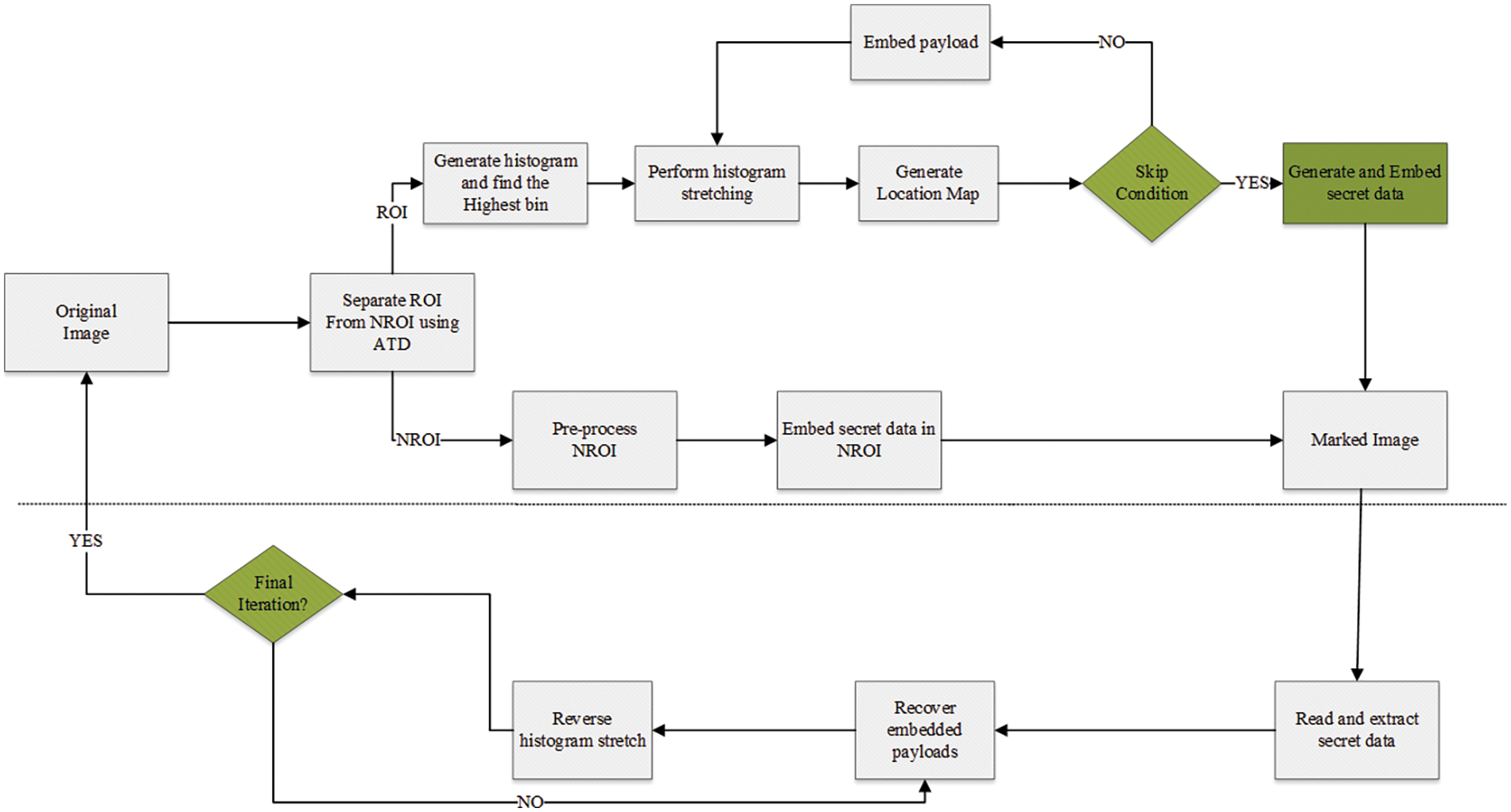
Figure 1: Diagram depicting the proposed algorithm
This section will initially delve into the contrast enhancement for medical images (RDHACEM) in [1], preceded by the proposed pairwise reversible data hiding for medical images with contrast enhancement based on target shifting of histogram bins of the region of interest (ROI) of medical images.
2.1 Thresholding (Segmentation of ROI and NROI)
RDHACEM proposed a more flexible approach to threshold selection by the use of adaptive threshold selection (ATD), which strikes a balance between a class’s class interval, data size, and standard deviation by adjusting two parameter values [1]. Pixel values that are below the threshold will remain at 255, while those that are beyond it will be changed to zero, as shown in Eqs. (1) and (2) in segmentation. Eq. (1) illustrates the thresholding process, denoting the initial pixel and the altered pixel following thresholding. Pixel values that are below the threshold will remain at 255, while those that are over the threshold will be changed to zero. Eq. (1) illustrates the thresholding process, denoting the initial pixel and the altered pixel following thresholding. Pixel values that are below the threshold will remain at 255, while those that are over the threshold will be changed to zero.
Using the threshold image used by Eq. (1), the original image is then segmented into ROI and NROI using Eq. (2), where and represent the pixels in the first and last columns of a row, denoted as and respectively, where the pixel values are 0, and represents the column number of the current pixel, to undergo modification. Specifically, the pixels located between the column indices and within a row is set to zero, while the remaining pixels will remain unchanged.
The histogram represented in Fig. 2 shows a typical distribution of an images ROI of grayscale images, where bins in histogram are clustered in a particular region of intensity (luminance).
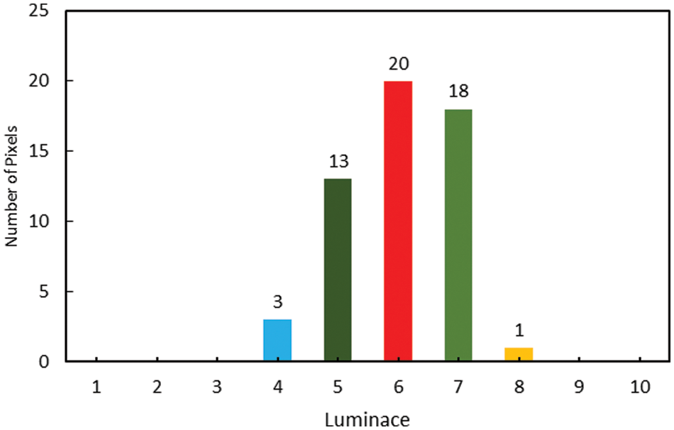
Figure 2: Example of histogram with ROI
The condition applies to pixels whose column index is between
This paper proposes a pairwise RDH for medical images with contrast enhancement (CE) based on target histogram stretching of ROI histogram bins. The proposed method ultimately applies an equalized number of iterations in embedding secret data into the ROI of medical images but delivers an enhanced contrast medical images than the method used in [1] in enhancing the ROI of medical images. The proposed method performs stretching by focusing on the bin with the maximum number of pixels in the histogram of the ROI medical image. Outlines for performing target stretching are listed below and illustrated in Eqs. (3)–(9).
1. Identify the pivot bin
2. On the left side, find the bin with the lowest intensity value
3. Move the pixels from the bins at the extreme ends toward 0 on the left and 255 on the right. As each bin is shifted, the subsequent bin assumes it previous position.
Here, the target stretching of the histogram method is used where the bins to the left of the pivotal bin (the bin with the highest number of pixels) are stretched towards the start of the histogram, and the bins to the right are stretched towards the end. The selection of the pivotal or highest bin is implied in Eq. (3), as shown below. Let
where
The position
When histogram bins are moved as part of the histogram stretching process, the subsequent bins must be adjusted to maintain the continuity of the histogram. For both the low and high-intensity stretches, this can be defined in mathematical expressions in Eqs. (6) and (7) as shown below. For low-intensity stretch, after moving the pixels from a bin to a new position, the subsequent bins need to shift to the left to fill the gap. This can be expressed in Eq. (6), assuming position for the preceding bins after the shifting bin to
The expression in Eq. (6), states that for every bin index
Eq. (7) implies that for every bin index
This implies that bins between the leftmost non-empty bin and the pivot are sequentially moved one bin towards the leftmost position, for
Eq. (8) implies that after L is moved to
This implies that bins are being shifted one position to the right, up to the position R.
Eq. (9) implies that after R is moved to
Fig. 3, depicting the pivot bin, can be defined as the one with the highest pixel value, which in the histogram is bin 6 with a pixel value of 20. From Eq. (8), bins to the left of the pivot
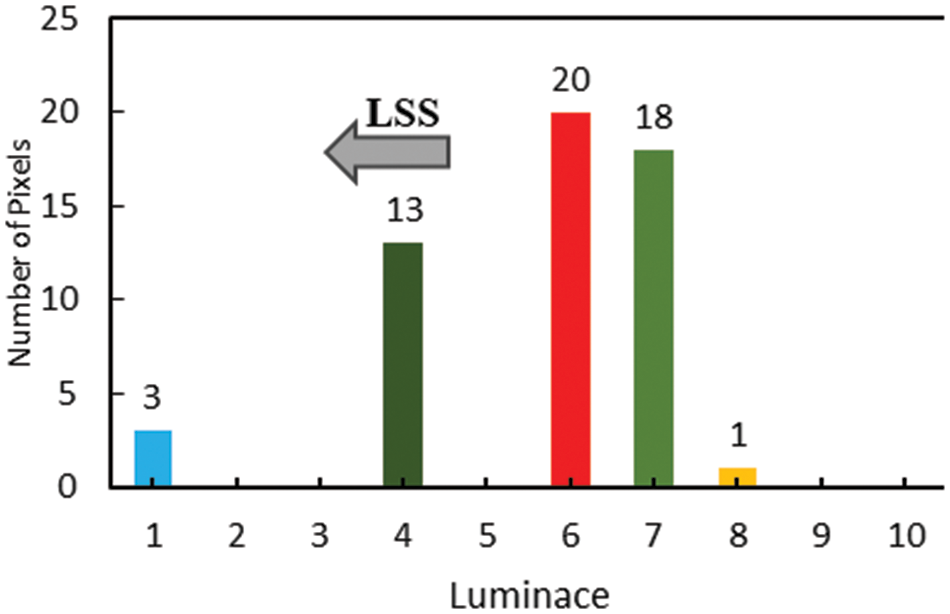
Figure 3: Left side stretching
Fig. 4 identifies the bin with the highest pixel value less than the maximum index, which is bin 8 with a pixel value of 1. Find the nearest extreme empty bin to the right of bin 8, which is index 10, and shift the pixel value of bin 8 into index 10, shift each bin value between bin 7 and bin 8 to the right by one position; creating a new empty index where bin 8 used to be (which is index 7). By repeating these steps, histogram bins of the region of interest will be stretched, creating space for data embedding. The empty spaces (or zero-value bins) that results from stretching process is to be used to embed the data bits.

Figure 4: Right side stretching
2.2.1 Skip Condition for Target Stretching
Left side stretch (condition): If there is no index

In the proposed method, data are embedded using a novel approach which compares histogram bins in pairs from left to right with three detailed conditions: Bin comparison: From Figs. 4 and 5, histogram of the ROI illustrated in Fig. 2 is stretched us evenly a target histogram stretching as discussed earlier.

Figure 5: Embedding processes of ROI image histogram
Fig. 5 shows the embedding processes after the ROI image is stretched to increase embedding capacity. Fig. 5a: compares bins in 1 with that of 4 to select the bins with the greater number of pixels to embed. It can be expressed as Let denote the number of pixels in bin i. To determine which bin to select for embedding based on a comparison between any two bins, as shown in Eq. (11) below:
Available space checks: It then checks for empty space(s) on the left and right side of the bin with the greatest number of pixels to direct the movement of the data being embedded. Here, bin 1 with 3 pixels and bin 4 with 13 pixels indicate that bin 4 with 13 pixels is greater than bin 1. Therefore, data is embedded in bin 4; while comparing the number of empty spaces available on the right and left of bin 4 again to direct data embedding direction: On the left side of bin 4, 2 and 3 are empty on the left whilst 5 is empty on the right. Therefore, we embed it on the left; this will be the first iteration. It can be represented as: For the left side of the selected bin:
For the right side of the select bin p;
Embedding direction: This is done to employ the existing empty space efficiently and to minimize any potential distortion in the image’s histogram that might occur due to the embedding process. Compare
Count the number of empty bins to the right of the selected bin for embedding: denoted as
Fig. 5 illustrates the embedding criteria of the proposed method, applying condition from Eqs. (11)–(15). This process occurs after target stretching is deployed, creating enough space for embedding while enhancing contrast of medical images.

2.4 Embedding Data into Non-Region of Interest (NROI)
1. Preprocessing of NROI: The minimum gray value of the NROI region is identified and set to zero to prevent underflow during high embedding rates [7]. This is expressed in Eqs. (16) and (17).
2. Embedding of additional information: The information embedding process involves utilizing the least significant bits (LSBs) of pixels situated along the four edges of the image, where typically non-critical data is stored. Denoted as
where
3. Embedding data into NROI region: Histogram of the preprocessed NROI region is calculated while the peak bin is identified for data embedding. Data bits are embedded into the peak bin by incrementing the gray value of the peak bin to encode a bit of 1or leaving it unchanged to encode a bit of 0. Here,
While
Update the histogram to show the change:
Choose the new peak bin after the histogram update:
Increment
The above processes describe the iterative procedure in which each time a bit is embedded, the peak bin is chosen again and the histogram is updated for the subsequent bit. Until all n bits of secret data are implanted into the medical image’s NROI region. The updated pixel value after data embedding can be represented as
where g is current pixel of gray value in the NROI, gv is the gray value of the peak bin in the NROI histogram and s is the secret data bit to be embedded (either 0 or 1).

2.5 Difference Expansion, Prediction Error-Based Approach
1. Difference Expansion involving the expanding the difference between pair of pixel values or bins to embed data. In respect with our proposed work, modifying the value of a bin
where
2. Prediction error-based approach in pixel’s value is predicted on the neighbouring pixels. The error (difference) between the actual pixel value and the predicted value is to embed data. Expression for embedding a bit using prediction error is represented as:
where
In this paper, we chose different medical images from the NBIA [24] and Medpix [25] databases for our experiments, particularly focusing on the algorithm comparisons with ACERDH in [26], RHCRDH [27], RDHACEM [1], and ACERDHBS [8] with the proposed method. However, the number of images that we chose was restricted to six. Keeping this limitation in place was essential in order to keep the comparison between the algorithms that were being studied limited and direct. The size of these images, which are referred to as “Brain01,” “Brain02,” “Chest01,” “Chest02,” and “Chest03,” as well as “Xray,” varies.
Among the initial five photos, the “Xray” image is 256 × 256 pixels, while the remaining five images are 512 × 512 pixels. For the purpose of conducting experiments with the RDHACEM algorithm, the images “Chest01” and “Xray” were specifically utilized [1] is the reference for this algorithm. For the most part, the purpose of this article is to examine the similarities and differences between our recently suggested method and the RDHCEM algorithm in terms of their capability to embed data and their capacity to significantly improve image contrast. The purpose of the experiments that are being carried out with the remaining images is to demonstrate the effective visual enhancements that can be achieved through the contrast improvement strategies that are utilized by the proposed algorithm.
Fig. 6 of this study contains a representation of these six medical images, the selection of the medical images is limited to the experiment of this paper considering limitation in space, with all experimental analysis of marked image of 2 bit per pixel (bpp), which is the highest rate of embedding in this paper.
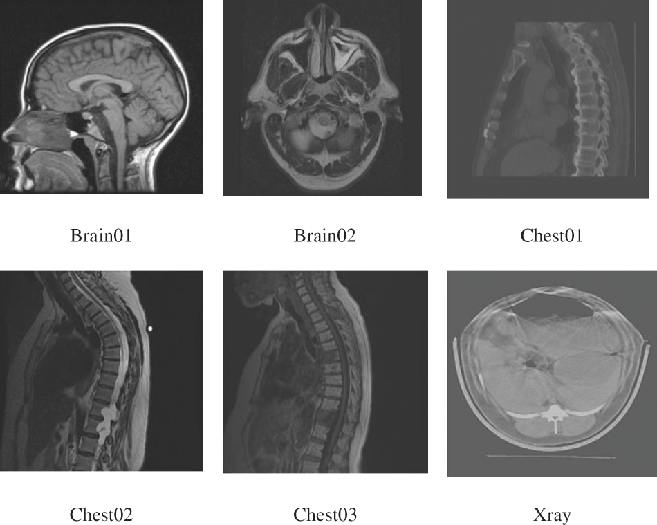
Figure 6: Medical images from NBIA and Medpix
The original and stretched ROI histogram distribution of Brain01 and Brain02 are presented in Fig. 7. In comparison with the original distribution in Figs. 7a and 7d, the stretched histogram obtained by RDHACEM algorithm Figs. 7b and 7e, it can be observed that the proposed algorithm achieves a more uniform distribution as shown in Fig. 7c and 7f. The proposed algorithm stretches the ROI histogram wide averagely across all grayscale values simultaneously enhancing the contrast of the ROI.
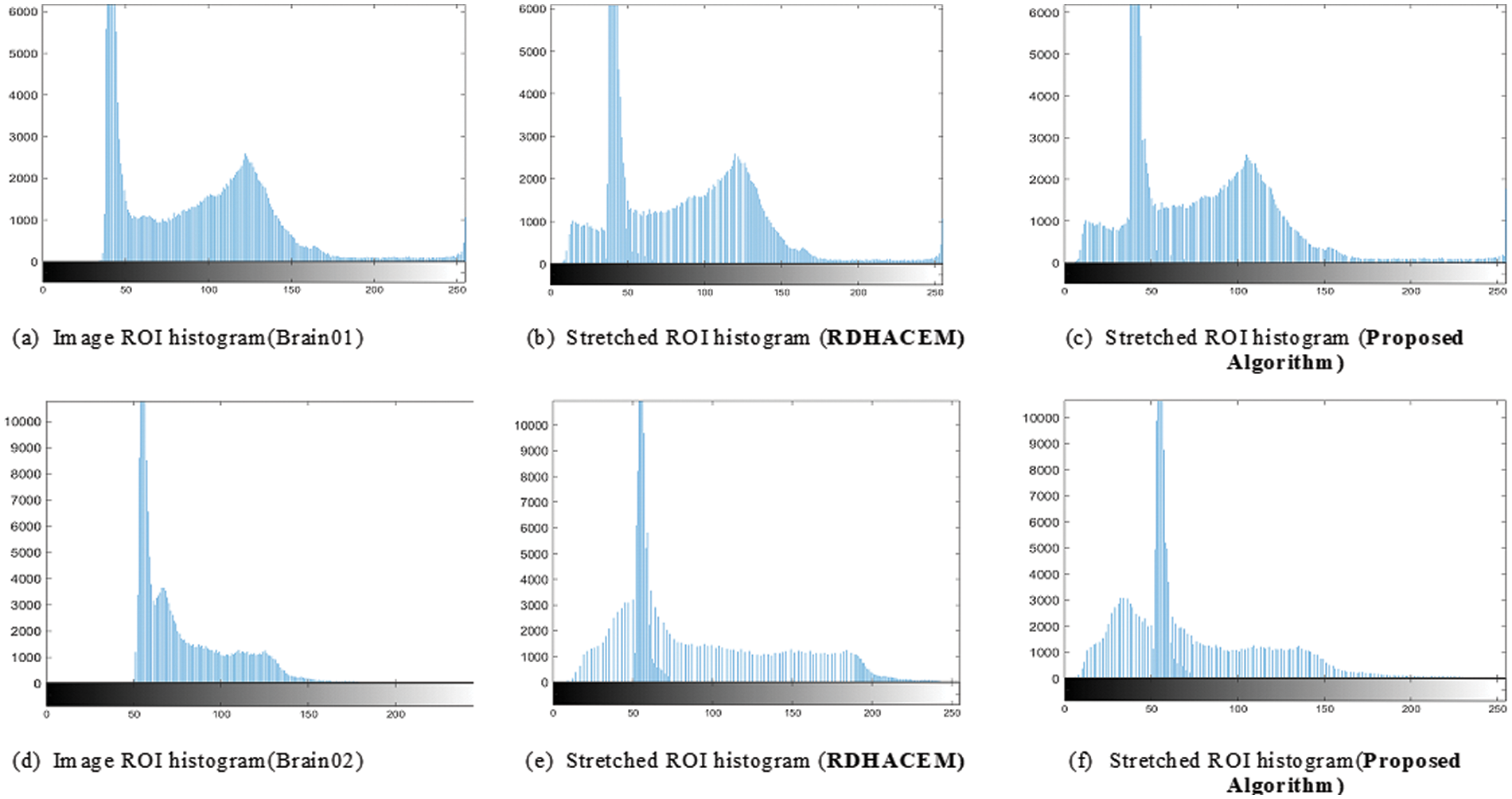
Figure 7: Original and stretched ROI histogram of Brain01 and Brain02, (a), (d) using RDHACEM, (b), (e) and proposed algorithm (c), (f)
From Fig. 8 comparing Figs. 8a–8d, it is depicted that the proposed approach in Fig. 8e embeds 61966 bits, but the algorithms ACERDH, RHCRDH, RDHACEM, ACERDHBS can embed 11732, 11566, 33232 and 61722 bits respectively, into the ROI of the “Xray” image. Regarding, ‘Chest01’ image, the proposed method embeds 387188 bits into the ROI of the image depicted in Fig. 8j, while the ROI permits a sum of 13134, 1038, 381433 and 387094 bits using the ACERDH, RHCRDH, RDHACEM and ACERDHBS algorithms.

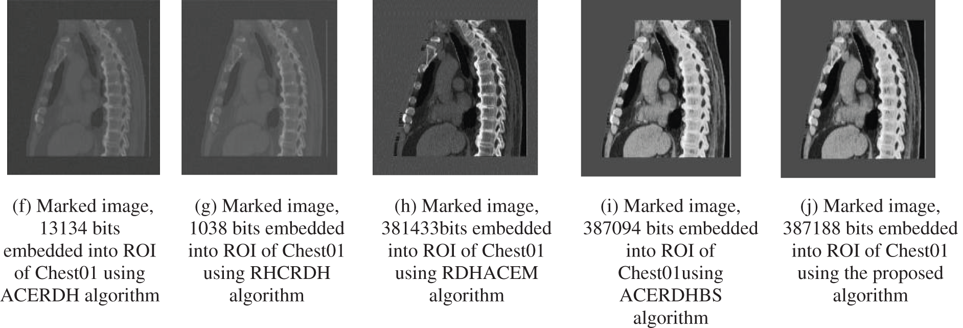
Figure 8: Marked images, Xray and Chest01 images (a–j) are marked images with data embedded into the ROI
The two images in Fig. 8: Xray and Chest01, the embedding rates of the algorithms ACERDH, RHCRDH, RDHACEM, ACERDHBS and the proposed approach at a rate of 2 bpp is used for each algorithm. This indicates that the proposed algorithm attains a greater embedding capability. Similarly, compared to the ACERDH, RHCRDH, RDHACEM and ACERDHBS algorithms, the medical images produced by the proposed method exhibit empirical visual improvement.
3.1 Metrics of Performance Evaluation
In this study, we utilize five distinct metrics for evaluating image quality, namely peak signal-to-noise ratio (PSNR), structural similarity index (SSIM), relative contrast error (RCE), relative mean brightness error (RMBE), and mean opinion score (MOS). These metrics are employed to assess the quality of the enhanced images generated by the ACERDH, RHCRDH, RDHACEM, ACERDHBS and the newly proposed method outlined in this paper.
PSNR serves as a widely recognized measure for evaluating image quality, calculated as the ratio between the maximum signal power and the power of the signal’s noise. The SSIM index is a perceptual metric aimed at quantifying similarities between original and enhanced images. Relative contrast error (RCE) compares contrast levels using standard deviation, where RCE values above 0.630 indicate enhanced contrast, while values below 0.630 indicate reduced contrast. Relative mean brightness error (RMBE) assesses the average brightness difference between original and enhanced images. The evaluation results of ACERDH, RHCRDH, RDHACEM, ACERDHBS and the proposed method are based on these five quality assessment criteria and are limited to 2 bpp of secret data due to space factor for this paper as illustrated in Tables 1–4.


Fig. 9 presents a visual comparison of marked images of Brain01 at an embedding rate of 2 bpp of ACERDH, RHCRDH, RDHACEM, ACERDHBS with the proposed method. Indicating its performance metrics in Table 1.

Figure 9: Marked images of “Brain01” using the ACERDH, RHCRDH, RDHACEM, ACERDHBS and Proposed algorithms at 2 bpp
As presented in Table 1, the SSIM, which qualifies the structural similarity between the original and marked images, without taking into account any enhancements in image contrast. ACERDH and RHCRDH achieved greater SSIM values due to the absence of the application of global image modification, which implies that the entire image was modified uniformly without considering its structure. Despite the high SSIM values, both methods enhance the total image equally as observed in Fig. 9.
Fig. 10 presents visual assessment of marked images of Brain02 at an embedding rate of 2 bpp of ACERDH, RHCRDH, RDHACEM, ACERDHBS with the proposed method. Indicating its performance metrics in Table 2.

Figure 10: Marked images of “Brain02” using the ACERDH, RHCRDH, RDHACEM, ACERDHBS and Proposed algorithms at 2 bpp
The relative contrast enhancement (RCE) metric quantifies the contrast enhancement (CE) in images. As presented in Table 2. The proposed method achieved the greatest RCE value, suggesting its superior ability to enhance image contrast. It can be observed in Fig. 10, that marked image of the proposed method is enhanced in contrast.
Fig. 11 presents visual evaluation of marked images of Chest02 at an embedding rate of 2 bpp of ACERDH, RHCRDH, RDHACEM, ACERDHBS with the proposed method. Indicating its performance metrics in Table 3.

Figure 11: Marked images of “Chest02” using the ACERDH, RHCRDH, RDHACEM, ACERDHBS and proposed algorithms at 2 bpp
Regarding RMBE, Table 3 presents that the proposed algorithm offers a balanced trade-off, achieving a good compromise between the more extreme values. While not having the absolute lowest RMBE, it still outperforms two of the existing algorithms (ACERDH and RHCRDH), indicating an improvement in preserving image brightness over these methods. This, combined with other metrics like PSNR, SSIM, RCE, and MOS, makes the proposed algorithm a competitive and well-rounded choice.
Fig. 12 is a visual evaluation of marked images of Chest03 at an embedding rate of 2 bpp of ACERDH, RHCRDH, RDHACEM, ACERDHBS with the proposed method, indicating its performance metrics in Table 4.
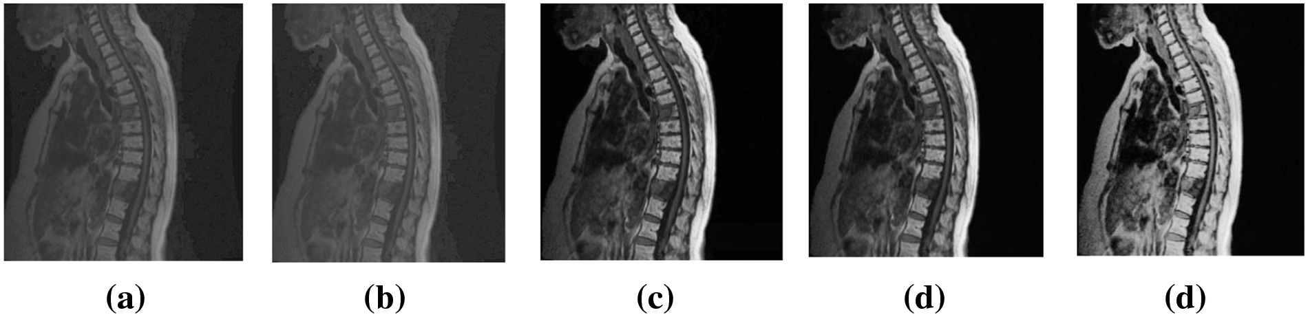
Figure 12: Marked images of “Chest03” using the ACERDH, RHCRDH, RDHACEM, ACERDHBS and proposed algorithms at 2 bpp
The MOS results presented in Table 4 represent the evaluations provided by healthcare professionals when assessing the prognosis of the case utilizing each improved image. The results demonstrate that the proposed method consistently produced higher-quality images compared to the existing method for all test images. This suggests that the enhanced images generated by the proposed method are more suitable for diagnosis and treatment, among other methods.
As the results suggested, PRDHMCE algorithm represents a significant development in the field of medical image processing, especially in terms of improving the contrast and embedding ability of grayscale medical pictures. The study demonstrates how the algorithm may effectively enhance the region of interest (ROI) while maintaining the non-region of interest (NROI) to provide processed medical images with better visual quality. It is essential to prioritize strengthening the embedded data security in future development. Investigating cutting-edge encryption methods that guarantee the integrity and secrecy of the embedded data may be one way to do this.
Further work needs to be done to improve the decryption procedure in order to preserve the integrity of the data that is retrieved and enable effective extraction. The goal would be to create a reliable system that offers a safe framework for the transfer and archiving of private medical data in addition to improving image quality and embedding capacity.
Acknowledgement: The authors would like to express their gratitude to the editors and anonymous reviewers for their insightful suggestions.
Funding Statement: This work was supported in part by the National Natural Science Foundation of China under Grant No. 61662039, in part by the Jiangxi Key Natural Science Foundation under No. 20192ACBL20031, in part by the Startup Foundation for Introducing Talent of Nanjing University of Information Science and Technology (NUIST) under Grant No. 2019r070, and in part by the Priority Academic Program Development of Jiangsu Higher Education Institutions (PAPD) Fund.
Author Contributions: The authors confirm contribution to the paper as follows: study conception and design: I. A. Boateng; data collection: I. A. Boateng, L. Amoah; analysis and interpretation of results: I. A. Boateng, L. Amoah, T. A. Isogun; draft manuscript preparation: I. A. Boateng, T. A. Isogun. All authors reviewed the results and approved the final version of the manuscript.
Availability of Data and Materials: The datasets generated during and/or analyzed during the current study are not publicly available but are available from the corresponding author on reasonable request.
Ethics Approval: This study was conducted using existing public medical image datasets with all relevant references in the manuscript.
Conflicts of Interest: The authors declare that they have no conflicts of interest to report regarding the present study.
References
1. G. Gao, S. Tong, Z. Xia, B. Wu, L. Xu and Z. Zhao, “Reversible data hiding with automatic contrast enhancement for medical images,” Signal Process., vol. 178, pp. 107817, 2021. doi: 10.1016/j.sigpro.2020.107817. [Google Scholar] [CrossRef]
2. Y. Li, S. Yao, K. Yang, Y. A. Tan, and Q. Zhang, “A high-imperceptibility and histogram-shifting data hiding scheme for JPEG images,” IEEE Access, vol. 7, pp. 73573–73582, 2019. doi: 10.1109/ACCESS.2019.2920178. [Google Scholar] [CrossRef]
3. A. C. Gangwar, “A comparative study of different histogram equalization algorithm for contrast enhancement,” IJSTE, vol. 2, no. 8, pp. 64–66, 2016. [Google Scholar]
4. H. T. Wu and H. M. Q., “Reversible contrast enhancement for medical images with background segmentation,” IET Image Process., vol. 14, no. 2, pp. 327–336, 2020. [Google Scholar]
5. L. Y. Muhammad, “A novel technique for analysing histogram equalized medical images using superpixels,” Comput. Assist. Surg., vol. 24, no. 1, pp. 53–61, 2019. [Google Scholar]
6. J. Wang, J. Ni, X. Zhang, and Y. Q. Shi, “Rate and distortion optimization for reversible data hiding using multiple histogram shifting,” IEEE Trans. Cybern., vol. 47, no. 2, pp. 315–326, 2016. doi: 10.1109/TCYB.2015.2514110. [Google Scholar] [PubMed] [CrossRef]
7. W. Wang and W. Wang, “HS-based reversible data hiding scheme using median prediction error,” Multimed. Tools Appl., vol. 79, no. 25–26, pp. 18143–18165, 2020. doi: 10.1007/s11042-020-08682-3. [Google Scholar] [CrossRef]
8. G. Gao and L. Amoah, “Automatic contrast enhancement with reversible data hiding using bi-histogram shifting,” J. Inf. Secur. Appl., vol. 68, pp. 103223, 2022. doi: 10.1016/j.jisa.2022.103223. [Google Scholar] [CrossRef]
9. K. Inoue, N. Ono, and K. Hara, “Local contrast-based pixel ordering for exact histogram specification,” J. Imaging, vol. 9, no. 8, pp. 247, 2022. doi: 10.3390/jimaging8090247. [Google Scholar] [PubMed] [CrossRef]
10. S. Yang, J. H. Oh, and Y. Park, “Contrast enhancement using histogram equalization with bin underflow and bin overflow,” in Int Conf. Image Process., Barcelona, Spain, 2003, vol. 1, pp. I–881. [Google Scholar]
11. H. T. Wu, X. Cao, R. Y. Jia, and Y. M. Cheung, “Reversible data hiding with brightness preserving contrast enhancement by two-dimensional histogram modification,” IEEE Trans. Circuits Syst. Video Technol., vol. 32, no. 11, pp. 7605–7617, 2022. doi: 10.1109/TCSVT.2022.3180007. [Google Scholar] [CrossRef]
12. S. Kim, R. Lussi, X. Qu, F. Huang, and H. J. Kim, “Reversible data hiding with automatic brightness preserving contrast enhancement,” IEEE Trans. Circuits Syst. Video Technol., vol. 29, no. 8, pp. 2271–2284, 2018. doi: 10.1109/TCSVT.2018.2869935. [Google Scholar] [CrossRef]
13. H. Chen, J. Ni, W. Hong, and T. S. Chen, “Reversible data hiding with contrast enhancement using adaptive histogram shifting and pixel value ordering,” Signal Process., vol. 46, no. 1, pp. 1–16, 2016. doi: 10.1016/j.image.2016.04.006. [Google Scholar] [CrossRef]
14. H. Wu, S. Tang, J. Huang, and Y. Shi, “A novel reversible data hiding method with image contrast enhancement,” Signal Process., vol. 62, no. 5, pp. 64–73, 2018. doi: 10.1016/j.image.2017.12.006. [Google Scholar] [CrossRef]
15. F. Chen, Y. Luo, J. Zhang, J. Zhu, C. Zhao and T. Wang, “An infrastructure framework for privacy protection of community medical internet of things,” World Wide Web, vol. 21, no. 1, pp. 33–57, 2018. doi: 10.1007/s11280-017-0455-z. [Google Scholar] [CrossRef]
16. Z. Xia, L. Lu, T. Qiu, H. Shim, X. Chen and B. Jeon, “A privacy-preserving image retrieval based on ac-coefficients and color histograms in cloud environment,” Comput. Mater. Cont., vol. 58, no. 1, pp. 27–44, 2019. doi: 10.32604/cmc.2019.02688. [Google Scholar] [CrossRef]
17. B. He, Y. Chen, Y. Zhou, Y. Wang, and Y. Chen, “A novel two-dimensional reversible data hiding scheme based on high-efficiency histogram shifting for JPEG images,” Int. J. Distrib. Sens. Netw., vol. 18, no. 3, pp. 15501329221084226, 2022. doi: 10.1177/15501329221084226. [Google Scholar] [CrossRef]
18. F. Ren, Y. Liu, X. Zhang, and Q. Li, “Reversible information hiding scheme based on interpolation and histogram shift for medical images,” Multimed. Tools Appl., vol. 82, no. 18, pp. 28445–28471, 2023. doi: 10.1007/s11042-022-14300-1. [Google Scholar] [PubMed] [CrossRef]
19. G. Su, G. D. Lin, C. C. Chang, and C. C. Chang, “Privacy-preserving reversible data hiding for medical images employing local rotation,” J. Healthc. Eng., vol. 2021, pp. 5709513, 2021. doi: 10.1155/2021/5709513. [Google Scholar] [PubMed] [CrossRef]
20. V. Kumar, C. Natarajan, and V. S. D. Muraledharan, “Difference expansion based reversible data hiding for medical images,” in Conf. Commun. Signal Process., Melruvathur, India, 2014, pp. 720–723. [Google Scholar]
21. J. H. Horng, C. C. Chang, G. L. Li, W. K. Lee, and S. O. Hwang, “Blockchain-based reversible data hiding for securing medical images,” J. Healt. Eng., vol. 21, no. 1, pp. 9943402, 2021. [Google Scholar]
22. R. Bhardwaj, “Hiding patient information in medical images: An enhanced dual image separable reversible data hiding algorithm for E-healthcare,” J. Ambient Intell. Humaniz. Comput., vol. 14, no. 1, pp. 321–337, 2023. doi: 10.1007/s12652-021-03299-2. [Google Scholar] [CrossRef]
23. S. Mansouri, H. K. Bizaki, and M. Fakhredanesh, “Reversible data hiding with automatic contrast enhancement using two-sided histogram expansion,” J. Vis. Commun. Image Represent., vol. 81, no. 10, pp. 103359, 2021. doi: 10.1016/j.jvcir.2021.103359. [Google Scholar] [CrossRef]
24. The National Library of Medicine, “Medpix,” Accessed: Nov. 01, 2022. [Online]. Available: https://medpix.nlm.nih.gov [Google Scholar]
25. National Cancer Institute, “National Biomedical Imaging Archive,” Accessed: Nov. 02, 2022. [Online]. Available: https://imaging.nci.nih.gov [Google Scholar]
26. S. Kim, R. Lussi, X. Ou, and H. Kim, “Automatic contrast enhancement using reversible data hiding,” in Conf. Inf. Forensics Secur. Italy, Rome, 2015, pp. 1–5. [Google Scholar]
27. Y. Yang, W. Zhang, D. Liang, and N. Yu, “A ROI-based high-capacity reversible data hiding scheme with contrast enhancement for medical images,” Multimed. Tools Appl., vol. 77, no. 14, pp. 18043–18065, 2018. doi: 10.1007/s11042-017-4444-0. [Google Scholar] [CrossRef]
Cite This Article
 Copyright © 2024 The Author(s). Published by Tech Science Press.
This work is licensed under a Creative Commons Attribution 4.0 International License , which permits unrestricted use, distribution, and reproduction in any medium, provided the original work is properly cited.
 Downloads
 Citation Tools