
 Submit a Paper
 Propose a Special lssue
 Open Access
ARTICLE

Automated Angle Detection for Industrial Production Lines Using Combined Image Processing Techniques
1 Department of Mechanical Engineering, National Taiwan University of Science and Technology, Taipei, 106, Taiwan
2 Center for Intelligent Manufacturing Innovation, National Taiwan University of Science and Technology, Taipei, 106, Taiwan
* Corresponding Author: Pawat Chunhachatrachai. Email:
Intelligent Automation & Soft Computing 2024, 39(4), 599-618. https://doi.org/10.32604/iasc.2024.055385
Received 25 June 2024; Accepted 24 July 2024; Issue published 06 September 2024
 View Full Text
 Download PDF
Abstract
Angle detection is a crucial aspect of industrial automation, ensuring precise alignment and orientation of components in manufacturing processes. Despite the widespread application of computer vision in industrial settings, angle detection remains an underexplored domain, with limited integration into production lines. This paper addresses the need for automated angle detection in industrial environments by presenting a methodology that eliminates training time and higher computation cost on Graphics Processing Unit (GPU) from machine learning in computer vision (e.g., Convolutional Neural Networks (CNN)). Our approach leverages advanced image processing techniques and a strategic combination of algorithms, including contour selection, circle regression, polar warp transformation, and outlier detection, to provide an adaptive solution for angle detection. By configuring the algorithm with a diverse dataset and evaluating its performance across various objects, we demonstrate its efficacy in achieving reliable results, with an average error of only 0.5 degrees. Notably, this error margin is 3.274 times lower than the acceptable threshold. Our study highlights the importance of accurate angle detection in industrial settings and showcases the reliability of our algorithm in accurately determining angles, thus contributing to improved manufacturing processes.Keywords
Computer vision technologies have gained significant traction in various industrial applications [1–4], revolutionizing processes across production lines [5–8]. Despite these advancements, angle detection remains an underexplored domain, especially in its integration into industrial production lines. Accurate angle detection is crucial for tasks such as assembly, painting, and 3-dimensional (3D) scanning, where precise alignment and orientation of components are essential for quality and efficiency. However, several challenges complicate effective angle detection in industrial environments. Variability in object shapes, occlusions, and lighting conditions create significant obstacles, making it difficult to achieve reliable and consistent angle detection. Addressing these challenges is imperative to enhance the accuracy and reliability of angle detection algorithms in real-world industrial settings.
While computer vision techniques have been extensively employed for tasks such as object recognition [9–11] and segmentation [12–15], the application of angle detection algorithms within production environments remains limited [16–19]. The complexity of industrial settings, characterized by diverse object geometries and dynamic conditions, poses significant challenges for existing angle detection methods. Current algorithms often struggle to maintain accuracy and robustness, leading to inefficiencies and an inability to handle various complex circular objects.
The recent study conducted by Kayğusuz et al. [16] presents a novel machine vision algorithm aimed at detecting angles in industrial settings, particularly focusing on simple circular workpieces. By analyzing vectors extending from the center to the edges of the objects, the algorithm demonstrates efficacy in angle detection. Kayğusuz et al.’s research contributes valuable insights into machine vision applications for industrial angle detection, yet further advancements are necessary to address the complexities inherent in diverse industrial contexts.
The studies conducted by Shi et al. [17] and Wang et al. [18] employ deep learning techniques for object detection, specifically focusing on non-circular objects. However, due to the shape bias inherent in the utilized datasets, these methods encounter limitations when applied to circular objects. Additionally, Maji et al. [19] investigate the application of Convolutional Neural Networks (CNNs) for detecting angles within landscape datasets. As highlighted in the research, this approach to angle detection is novel but is primarily focused on non-industrial contexts.
Moreover, the integration of accurate angle detection by computer vision into industrial production lines is critical [20–24]. Computer vision technologies are instrumental in optimizing numerous operations, including assembly [25–27], scanning, painting, and quality control [28–30]. The precise detection of angles ensures the correct alignment and orientation of components, thereby enhancing manufacturing efficiency and product quality. Nonetheless, current angle detection methods often require extensive algorithmic understanding for configuration setup.
Addressing the need for automated angle detection in industrial settings is imperative to streamline production processes and enhance productivity [31,32]. By harnessing the power of computer vision technologies, there exists immense potential to develop robust and efficient angle detection algorithms tailored to the specific requirements of industrial production lines.
This paper aims to bridge the gap by presenting a methodology for automated angle detection, emphasizing its significance in optimizing manufacturing operations and paving the way for advancements in industrial automation. Our primary goal is to devise a methodology capable of effortlessly adapting to a wide range of objects, thereby enhancing the flexibility and efficacy of manufacturing operations. To achieve this, we address the challenge of angle detection within industrial production lines, avoiding the need of the data preparation such as data augmentation [33] and complex training procedures typically associated with Machine Learning or Deep Learning techniques [34,35]. These techniques often demand extensive training time and significant computational resources, particularly when utilizing Graphics Processing Unit (GPU) like Convolutional Neural Networks. However, the scarcity of semiconductor chips worldwide [36] renders relying solely on GPU-intensive approaches impractical. Therefore, employing traditional computer vision methods that do not rely on GPUs can reduce the demand for GPUs and indirectly lead to cost savings in equipment for the project.
In summary, our paper makes several key contributions:
- We introduce a novel image-processing-based algorithm designed to accurately detect angles of a wide range of objects within industrial settings, particularly focusing on circular objects.
- We apply comprehensive mathematical principles and computer vision techniques to develop and refine the proposed algorithm, ensuring its effectiveness and reliability in real-world applications.
- We provide valuable information and methodologies relevant to manufacturers and researchers in the manufacturing process for circular objects, offering insights that can be directly implemented to enhance automation processes and improve overall efficiency.
This paper is organized into several sections to guide the reader through the research process and findings systematically. Section 1 introduces the topic, the problem statement, and the significance of the study. Section 2 provides the background and application offering a detailed of the system design and application for angle detection. Section 3 outlines the methodology, including the mathematical principles and computer vision techniques employed in developing the automated angle detection algorithm. Section 4 presents the experimental setup, including the environment setup, implementation details, and evaluation metrics for assessing the algorithm’s performance. Section 5 discusses the results of the experiments, analyzing the proposed method’s performance and demonstrating its effectiveness in industrial applications. Section 6 provides a detailed analysis of the implications of the findings for industrial practices. Finally, Section 7 concludes the paper by summarizing the key contributions of the study, reflecting on the significance of the proposed methodology, and outlining directions for further exploration in the field of angle detection for industrial applications.
In this study, a manufacturing system designed for circular objects of varied shapes and sizes is presented. This system is designed for multipurpose to operate many industrial tasks on the circular objects such object 3-Dimensional (3D) scanning and assemble. The system comprises a rotatable platform, a centering mechanism to adjust the placed object on the center of the platform precisely, a vision system, and a robot arm for measurement operations and 3D scanning, as illustrated in Fig. 1. The implementation of the angle detection algorithm is detailed in the flow chart depicted in Fig. 2. The process commences with the input image, which is subjected to image classification to ascertain the class of the object. Subsequently, the image classification algorithm selects the appropriate configuration file for each object, facilitating further processing steps. However, the purpose of mentioning image classification algorithm which uses DenseNet-201 as the backbone, is to present an algorithm handle the configuration selection for each object. In this paper, the image classification algorithm will not be detailed because the focus is on demonstrating how the angle detection algorithm operates using the preset configuration. The algorithm then reads the configuration based on the object class, enabling a tailored approach for angle detection. The precise determination of angles is a crucial step that directly influences the subsequent manufacturing processes such as assembly, painting, and 3D scanning [28–30].
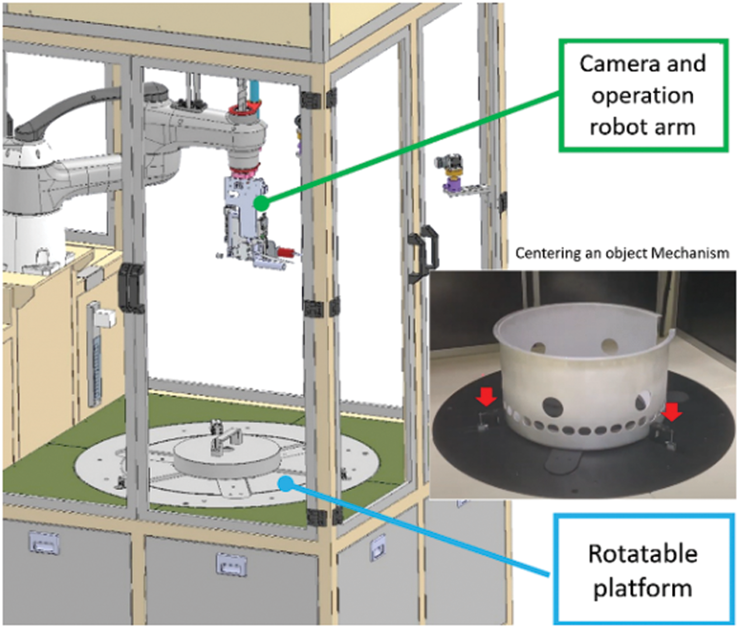
Figure 1: Machine system for angle detection operation system
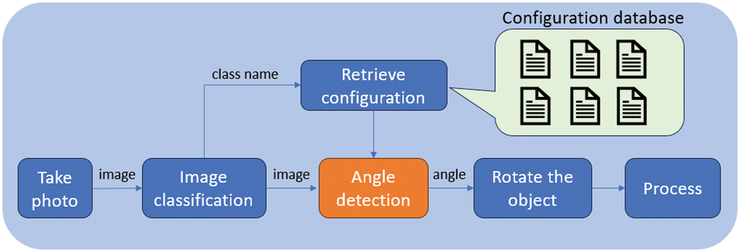
Figure 2: Overall flow chart of the project system
Upon successful angle detection, the algorithm directs the rotation of the object, paving the way for the initiation of specific processes such as scanning or painting. This sequence ensures that the industrial line dynamically adapts to the characteristics of each object, thereby optimizing manufacturing efficiency.
In the following sections, we detail the employed methodology, encompassing image processing techniques, contour selection, circle regression, polar warp transformation, outlier detection, and a unique angle calculation approach. The amalgamation of these elements forms the core of our training-free algorithm, contributing to a robust and adaptive solution for angle detection in industrial production lines.
The methodology employed in this study is centered around a comprehensive approach to angle detection within industrial production lines. Leveraging advanced image processing techniques, we amalgamate a series of algorithms to enhance accuracy and adaptability. The initial step involves combining multiple algorithms to form a cohesive image processing framework that allows the process to be adjustable for each case through configuration setup. Subsequently, contour selection is employed to extract the desired contours from the processed images, forming the foundation for subsequent analyses. To facilitate precise angle determination, circle regression is utilized, where the equation governing the regression process is outlined. The methodology incorporates Polar Warp Transformation using Open-Source Computer Vision Library (OpenCV) [37], employing specific equations to illustrate the transformation process. An essential step in the process involves the detection of outlier parts, achieved through contour identification. This intricate methodology ensures a robust and adaptive solution for automated angle detection in diverse industrial settings as shown in Fig. 3.
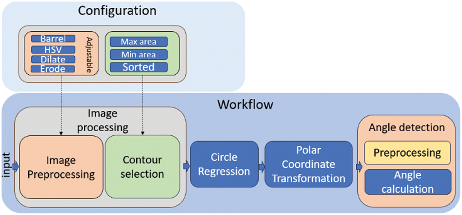
Figure 3: Flow chart of angle detection algorithm
In our approach, each object in the code is treated as an individual setup, incorporating a multitude of functions that can be customized and configured for specific parameter adjustments. The fundamental concept underlying our image processing methodology revolves around identification of a tailored sequence of image processing functions and parameter configurations to extract the contour of the unique part within the Region Of Interest (ROI). This individualized setup allows for a flexible and adaptive approach, accommodating the diverse characteristics of various objects encountered in industrial production lines.
In this study, we develop a low-code platform that utilizes configuration settings instead of hard-coding to individualize the process for each object, thereby enhancing customization efficiency and algorithm flexibility. With a diverse array of computer vision functions, including erosion, sharpening, blurring, thresholding for binarization, Hue, Saturation, Value (HSV) range adjustment, dilation, edge detection using Canny, Sobel filtering, barrel distortion correction, and cropping, it enables the execution of various combinations of these functions by setting the configuration differently.
For instance, object A is used as an illustrative example to elucidate the concepts including HSV color space in range, erosion, and dilation. In the preprocessing stage, the input image undergoes a series of operations within the individual setup. These operations may include techniques such as HSV color space to focus the interest of region, noise removal by erosion and dilation as shown in Figs. 4 and 5A,B, respectively. Following the preprocessing, the focus shifts to contour selection, a critical step in isolating the unique part of the region of interest.
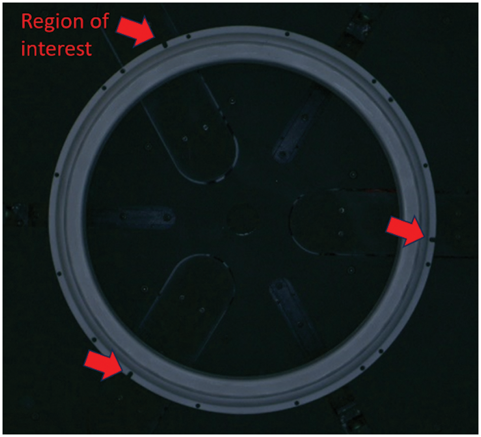
Figure 4: Original image of object A
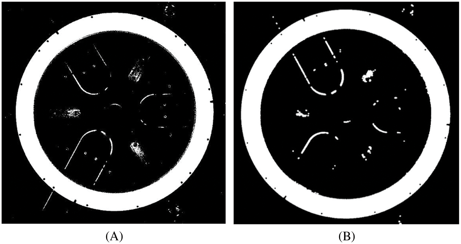
Figure 5: Image of object A after processing (A): HSV processing, (B): Erode and Dilate operations
The challenge of this algorithm is that a tiny unique part should be precisely detected for determination of the angle of the object. To tackle this challenge, we applied a function to expand the image in the radial direction using barrel distortion method.
The barrel distortion model, often expressed using the Brown-Conrady model, describes how the distorted coordinates (
where the terms
To correct barrel distortion, you need to invert these equations to find the undistorted coordinates (
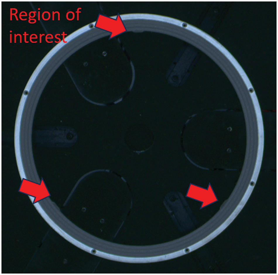
Figure 6: Original image of object B
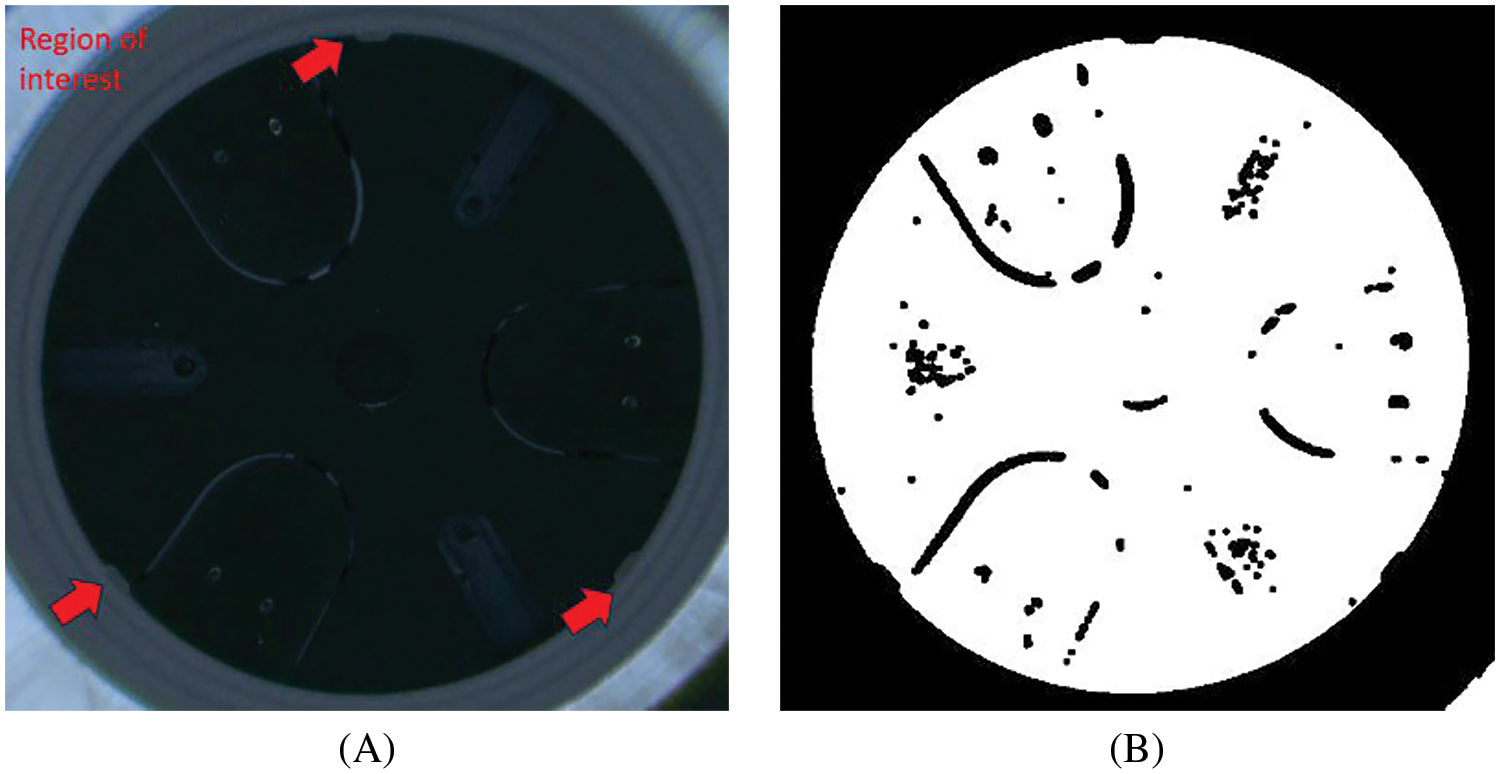
Figure 7: Image of object B after processing (A): barrel distortion (B): HSV processing
The purpose of contour selection is to delineate the area of the object that corresponds to the circular shape represents. This process places particular emphasis on isolating the center of the object, as it serves as a crucial reference point for subsequent steps. Specifically, the extracted contour is utilized in circle regression for determination of the circle’s parameters. This circle is then employed with warp polar transformation, facilitating the conversion of the circular image into a linear format. This transformation simplifies the angle calculation equation, streamlining the overall process.
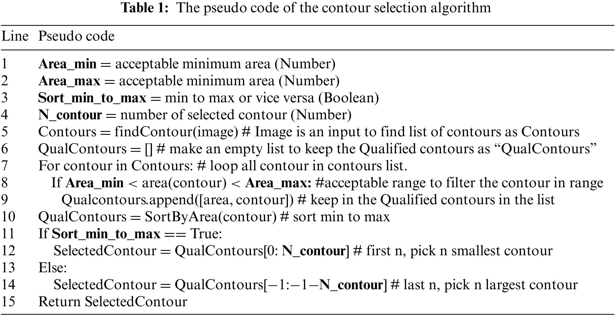
In the contour selection process, our system utilizes a variety of area filtering condition function which can be used for configuring the minimum and the maximum area and sorting contour in the order by small to large size or large to small size. This function will correctly select the desired contour to process in the next section of the algorithm. The parameters associated with each function can be adjusted through the UI and configuration settings, enabling fine-tuning to achieve optimal contour extraction. The contour selection algorithm will be explained by the Pseudo code in Table 1. In the first section of the Pseudo code is definition of variables which all are from the configuration and having data type in the bracket. Using “#” is the comments in the line of code to show the description of each line.
This tailored sequence of image processing functions ensures adaptability to diverse objects within the industrial production line, allowing for precise and efficient contour identification. The individual setup approach not only streamlines the image processing pipeline but also provides a user-friendly interface for operators to customize the system based on the unique attributes of each object, contributing to the overall flexibility and robustness of our methodology. These examples demonstrate contour selection on objects A and B, where the largest contour in each image is selectively chosen, as depicted in Fig. 8A,B, respectively.
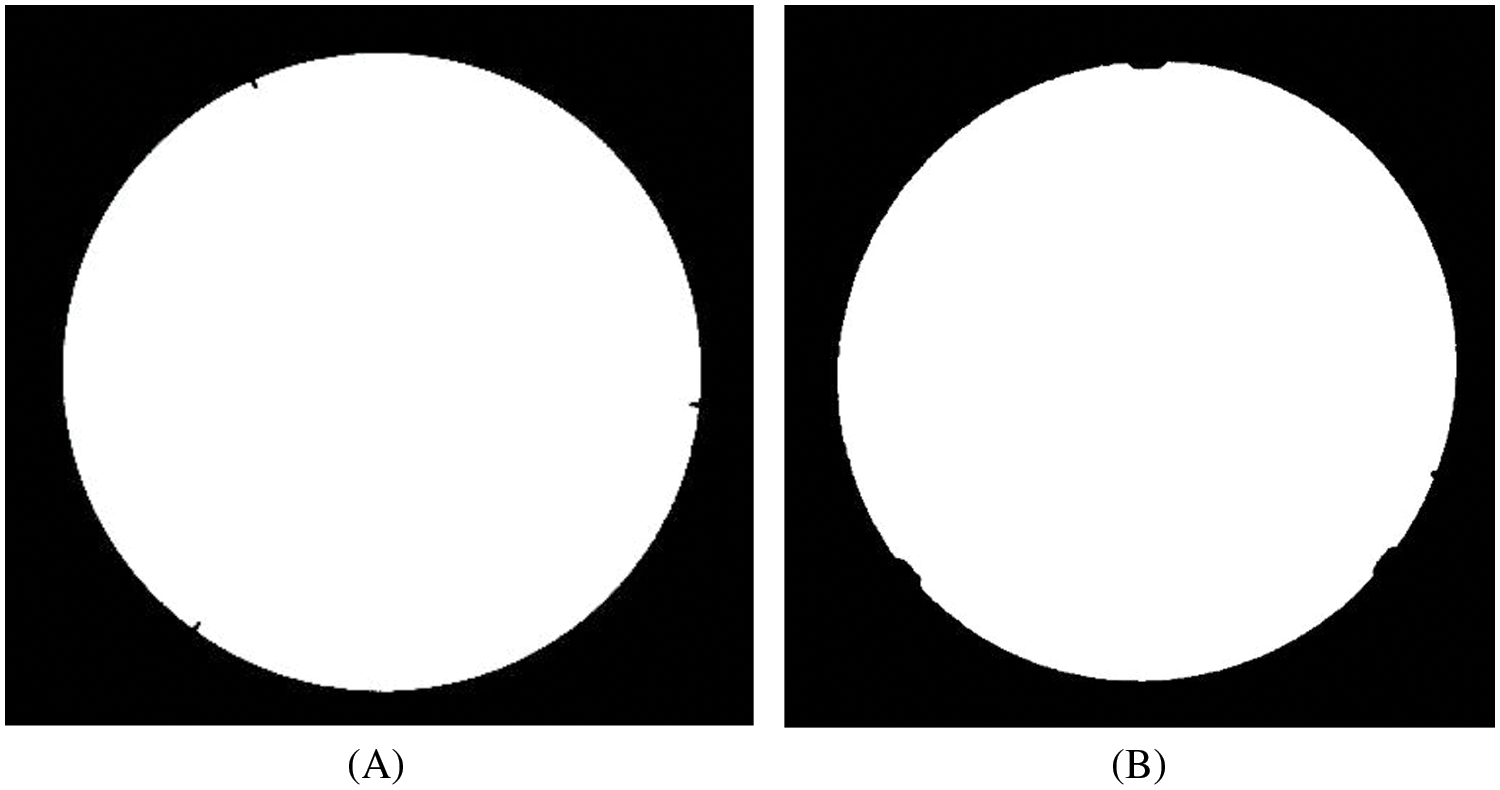
Figure 8: Contour selection (A): object A (B): object B
In this study, circle regression is utilized as the circle detection algorithm. Since the input images from the previous process contain distinct circles and single contours, circle regression does not require a parameter tuning process for inputting the function. In contrast, the Hough Circle method in OpenCV [36] necessitates input parameters. This is the rationale for selecting the regression model.
Circle regression is a type of regression analysis where the goal is to fit a circle to a set of data points. This can be useful in various applications such as computer vision, image processing, and geometric modeling.
When fitting a circle to a set of data points (
where (a, b) are the circle’s center coordinates, and r is the radius.
To achieve circle fitting, the objective is to determine values for a, b, and r that minimize the sum of squared distances or errors between the data points and the predicted circle. In this study, we employed a linearization method to solve the circle fitting, starting with the standard circle equation in (4):
where D, E, F can be calculated by the following equations:
By solving (4)–(7), we find values for a, b, and r, and perform a least squares linear regression to fit the equation. The example to show the circle regression is in Fig. 9.

Figure 9: Prediction circle and polar coordinates transformation
3.4 Polar Coordinate Transformation
This section aims to convert a circular image into a linear image through the use of polar coordinate transformation. The discussed transformation involves applying various geometric modifications to 2D images. Although these modifications do not change the content of the image itself, they alter the pixel grid’s shape and project this modified grid onto the resulting image. To maintain optimal quality and prevent distortion, the projection occurs in the reverse direction—from the output image back to the input. In this process, for every pixel (x, y) in the output image, the functions identify the corresponding original pixel in the input image and transfer its value.
The linear image can detect the unique part on the object with the optimal cost of computation, calculate the angle on the unique part by linear equation. The example of the polar coordinate transformation as in shown Fig. 9.
In this process, the function used for the polar coordinate transformation is sourced from the OpenCV library. OpenCV [36] provides a set of functions and tools for computer vision tasks, and in this specific application, an OpenCV function is employed to carry out the necessary geometric modifications and pixel grid transformations from circular to linear images.
3.5 Detecting Unique Part and Angle Calculation
In this section, the algorithm will process the linear image obtained from the previous step to calculate the angle of the object. The algorithm consists of two main steps. The first step is preprocessing, aimed at cleaning the image for angle detection and object calculation. The second step involves angle calculation, where the coordinates of the unique part are determined and converted into the angle of the object, as illustrated in Fig. 10.
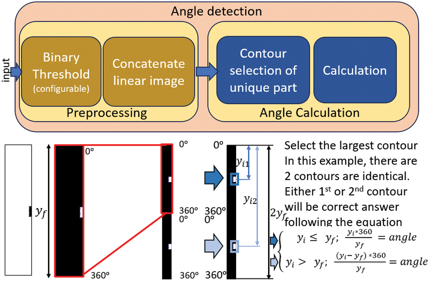
Figure 10: The workflow of angle detection section
In this stage, there is a configuration designed to regulate the processing of each object. The initial phase involves inversely binarizing the image to account for situations where the distinctive element is not situated within the white area. The subsequent phase focuses on the region of interest or the unique part of the object, addressing scenarios where other parts may be white in the image.
Moving on to the second phase, it holds significance as it deals with instances where the unique object is positioned at an angle between 0 and 360 degrees, as illustrated in Fig. 11. Without this step, the algorithm may encounter difficulties in selecting the correct contour in the subsequent stage. This step involves concatenating the image itself along the y-axis to ensure the unique part completes itself.
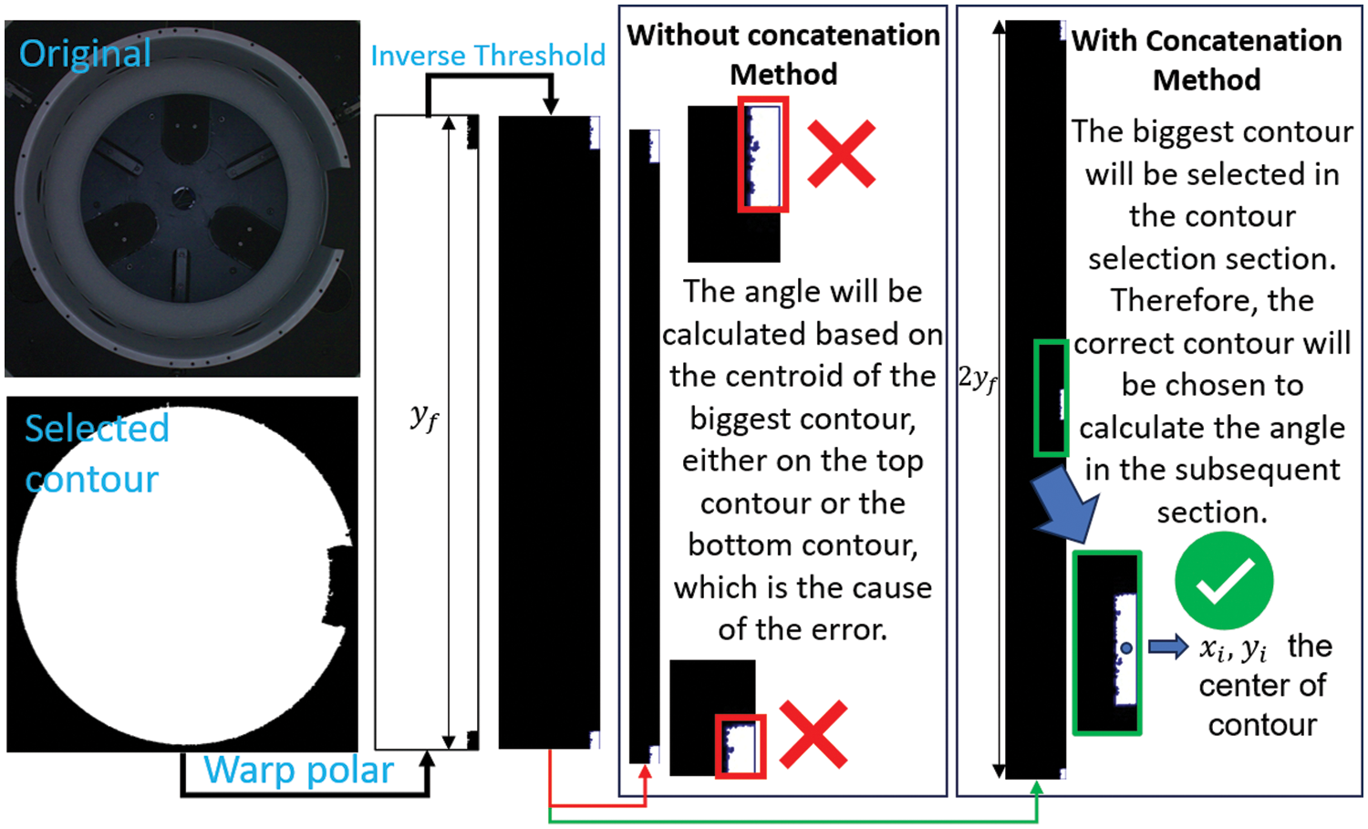
Figure 11: Comparison of with and without concatenation method
To illustrate the rationale behind the concatenation process, consider the unique part positioned between 0 and 360 degrees, as shown in Fig. 11. Without the concatenation method, the contours of this unique part would be split into two smaller contours. Consequently, the selected contour for angle calculation would only encompass a portion of the entire contour. However, employing the concatenation method ensures that the contour is fully integrated. A visual comparison of the results obtained with and without the concatenation method is presented in Fig. 11.
Subsequently, the preprocessing step is optimized, paving the way for transition to the next section, which involves angle calculation.
The purpose of this section is to calculate the angle of the object by finding the location of the unique part in the linear image and calculate the angle based on the Cartesian coordinate converting to angle of the object. There are two main parts in this section, the first selects contour and calculates the center of the contour in the linear image, and the second convert the contour’s coordinate to the angle by an algorithm backed with mathematic equations.
In contour selection of the unique part, the expected input image of the part should be a clean image expected to have only contours of the unique part or the biggest contour must always be the contour of the unique part. The condition to select the contour is the largest contour of the input image. The algorithm of the contour selection is the same with contour selection in the image processing section, but the parameters are fixed as no limit of minimum and maximum area and the largest contour will be selected.
In the last step in Fig. 10, the calculation section uses (8) to calculate the angle, given
The angle calculation process is determined by two conditions: firstly, if the center of the y-axis of the selected contour is lower than or equal to the circumference of the predicted circle, the above equation will be applied. Otherwise, if the center of the y-axis exceeds the circumference of the predicted circle, the below equation will be utilized:
In this study, we utilized a dataset consisting of 32 objects, each with diameters ranging from 30 to 70 cm, with the aim of detecting the angle of inclination for each object. To create the dataset, we randomly selected five different angles by controlling the rotatable platform, as described in the background section. As illustrated in Fig. 1, our system incorporates a rotatable platform designed to precisely capture data on the angle of rotation and is equipped with a mechanism to ensure that the object is centered. The following steps outline the process for creating and labeling the dataset:
1. Random Positioning: The object is randomly positioned at various angles on the platform.
2. Rotation to Reference Angle: The platform is rotated until the reference part of the object is at a 0-degree angle.
3. Accuracy Measurement: The accuracy of the rotation is measured using a laser measurement system.
4. Image Labeling: Each image of the object is assigned a label corresponding to its angle of rotation.
These steps ensure the precise and reliable labeling of the image data for the study. Of the five angles, two were reserved for the configuration setup process, while all five angles were utilized for algorithm evaluation. Some samples of the dataset are shown in Fig. 12.
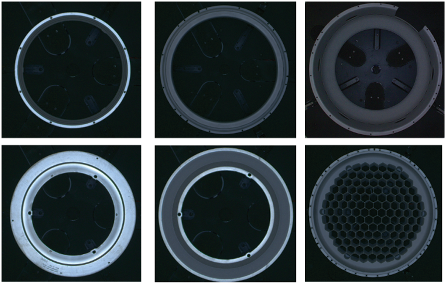
Figure 12: Sample of variance of object in the dataset
In this experiment, we utilized the HSV color space, which is sensitive to changes in lighting conditions. Therefore, the light environment was meticulously controlled and maintained at a constant level throughout the experiment, referred to as the control environment. Additionally, the objects were positioned at the center of the platform using the machine’s mechanism, as illustrated in Fig. 1. This setup ensures consistency and reproducibility and allows for the platform’s utilization in subsequent processes within the production line.
4.3 Evaluation Matric and Criteria
During the data collection phase, angle measurements were manually labeled by human operators. This process involved rotating the platform randomly and recording the angle selected at each instance. Subsequently, both labeled angles and angles predicted by the algorithm were obtained. To assess the performance of the algorithm, the absolute error as in Eq. (9) between labeled and predicted angles was calculated.
Notably, the labeled angles were sensitive to one decimal point accuracy, whereas predictions could have up to two decimal points. However, for consistency, the evaluation focused on the lowest decimal point, corresponding to the labeled angles. Thus, the minimum detectable error in this research was restricted to 0.1 degrees. In the context of this application, the precision demanded by the production line remains stringent, with an upper limit of 1 mm in diameter deviation. To ascertain the permissible error margin, the analysis focuses on the largest manufactured object, boasting a diameter of 70 cm, equivalent to a radius of 35 cm. By computing the error angle for the tangent, derived as the reciprocal of the radius, a value of approximately 1.637 degrees emerges. Thus, this figure represents the admissible error threshold for the production line, signifying the maximum allowable deviation from the ideal tangent angle during manufacturing processes. Adherence to this specified limit ensures compliance with the stipulated precision criterion, maintaining deviations below the designated 1 mm threshold at the diameter.
In this study, we delve into the realm of image processing to investigate the intricate relationship between algorithm performance, configurations, and expertise. Our research underscores the critical importance of comprehending algorithmic intricacies and establishing appropriate configurations before execution. To illustrate our findings, we present a sample outcome obtained through our research, providing a tangible example of the interplay between algorithm configurations and expertise in image processing in Fig. 13.
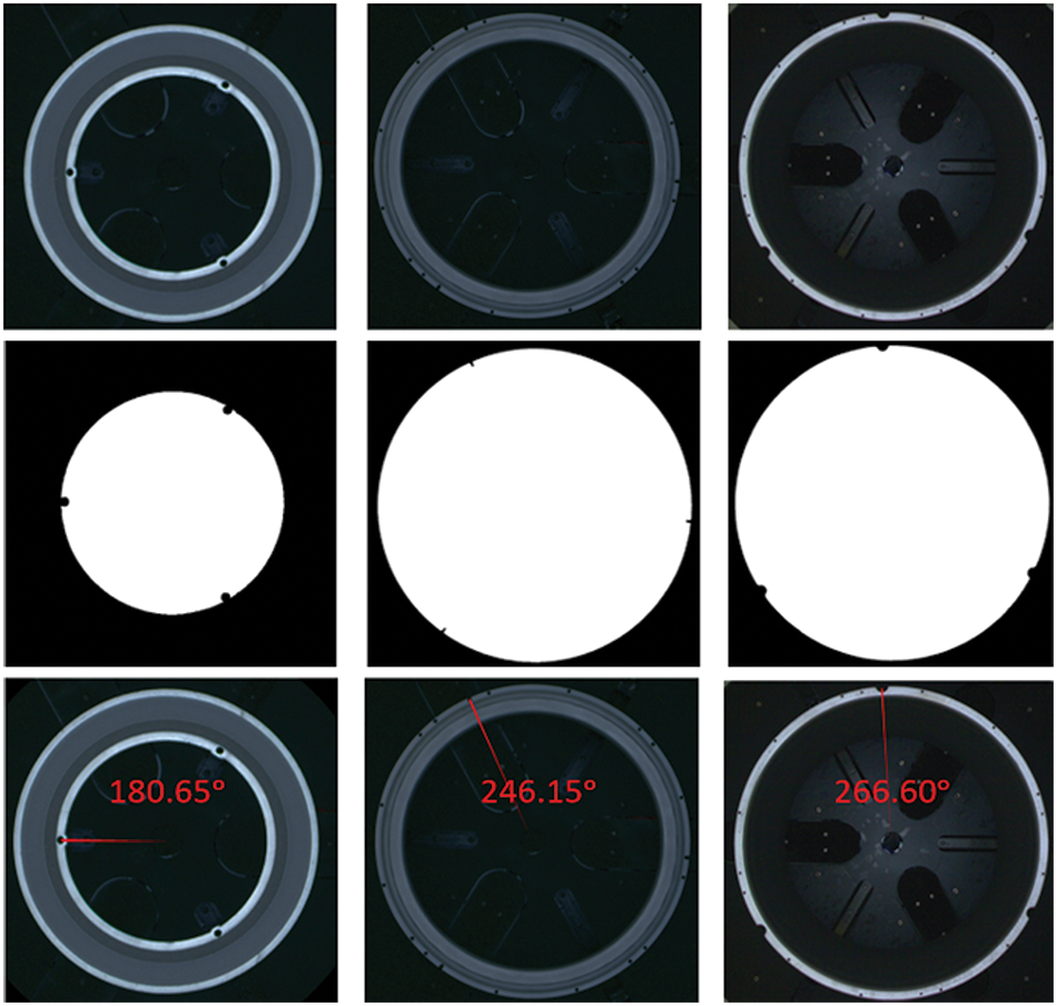
Figure 13: Sample result: original image (Top row), processed image (Middle row) as per the algorithm, result (Bottom row)
In addition to assessing the accuracy of angle detection, it is crucial to analyze the impact of various factors such as parameter settings and image preprocessing techniques on the results. Errors may arise from parameter settings and image preprocessing functions, particularly those that are sensitive to the position of the region of interest. Examples include barrel distortion, a non-linear function that expands the image, and morphological operations such as erosion and dilation, which alter the contour of objects.
In this study, we examine the impact of barrel distortion on object B, as described in the methodology section (Fig. 6). Barrel distortion can cause objects to appear distorted. To illustrate this, we measured the diagonal diameter of object B on both sides of the image as shown in Fig. 14. The measurements yielded diameters of 2.86 units and 2.94 units, respectively.
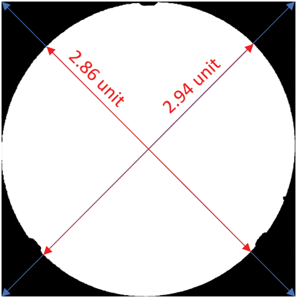
Figure 14: Visualization of distortion of barrel distortion processing on object B
Despite the slight discrepancy, this error does not significantly affect the results, as the error in the center of the circle is minimal. Subsequent processing can accurately handle angle detection. The final result for object B is still accurate as presented in Fig. 15.
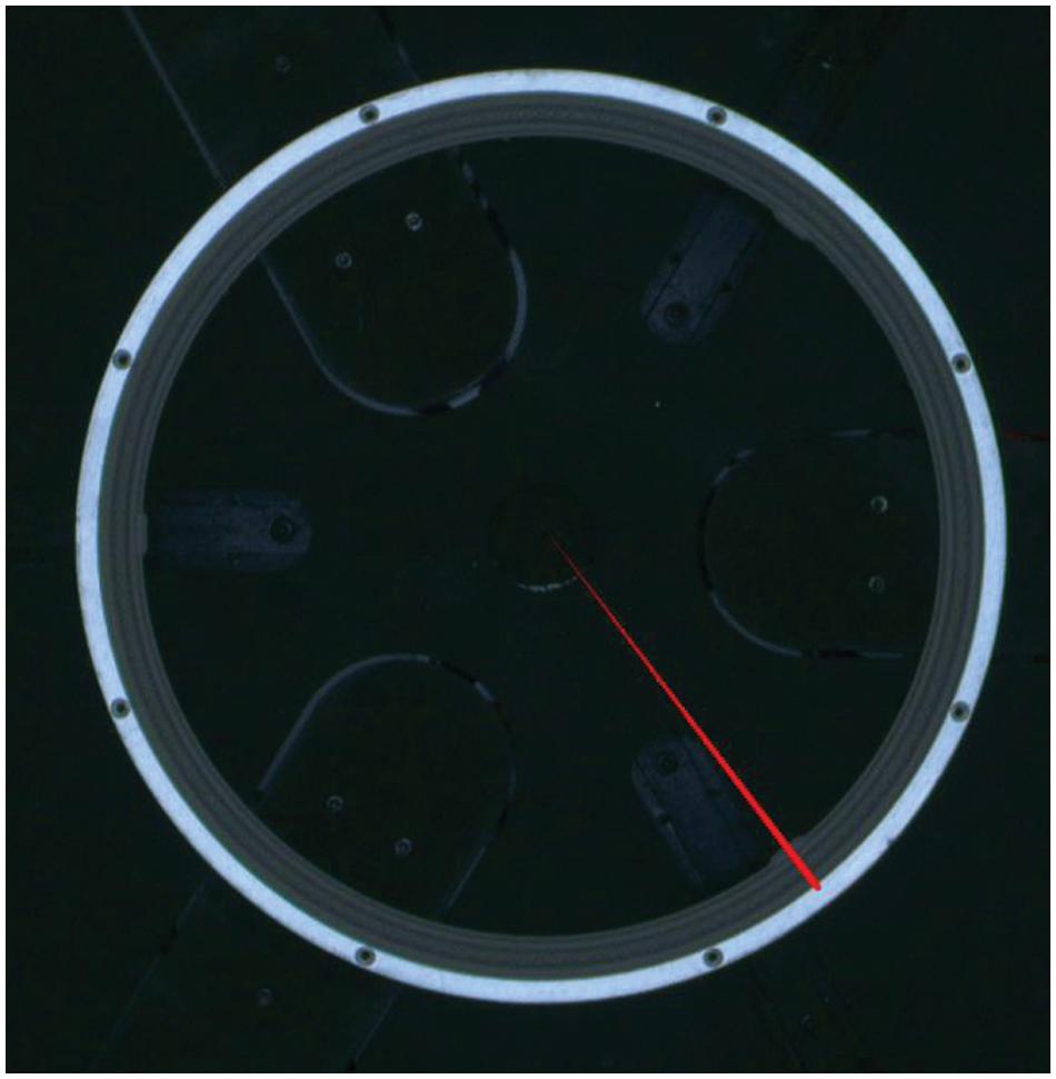
Figure 15: The result of angle detection algorithm on object B
The reliability of the algorithm depends on the quality of the contour selection in the input image for the circle regression process, as illustrated in Fig. 3. This implies that setting parameters is a crucial step, and barrel distortion is particularly sensitive to the quality of the object’s contour.
In our study, we found that configuring the algorithm with 29 out of 32 objects from the dataset yielded optimal results. Among the remaining 3 objects, which comprised circular symmetry objects, we observed no discernible impact on the algorithm’s operation. These objects were merely tagged onto the main dataset, as depicted in Fig. 16. Notably, the absolute error associated with the predicted angle was measuring only 0.5 degrees. The algorithm demonstrates a 0.5-degree error, which is 3.274 times lower than the acceptable error threshold specified in the evaluation metric and criteria section. This level of accuracy underscores the reliability of the algorithm in accurately determining angles.
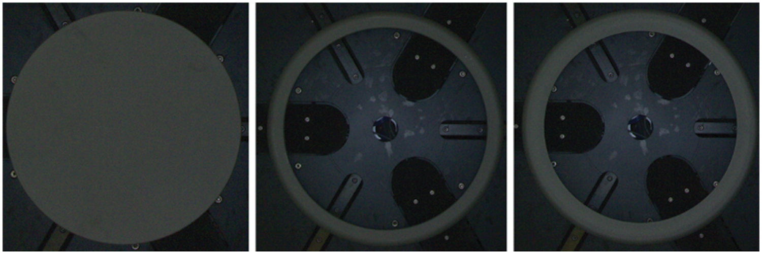
Figure 16: Objects incompatible with our algorithm
Our angle detection algorithm presents several advancements compared to existing approaches, particularly in its ability to handle a wide range of objects with unique parts while effectively addressing barrel distortion. In this section, we delve into the implications and significance of these contributions.
6.1 Flexibility in Object Handling
The flexibility of our algorithm in accommodating diverse circular objects with unique parts is a noteworthy feature. Traditional angle detection algorithms often struggle with objects that possess uncircular shapes [17,18] or simply single circular object [16], leading to suboptimal performance. By contrast, our algorithm offers a configurable framework that enables fine-tuning of parameters specific to individual objects. This adaptability enhances detection accuracy across a broad spectrum of objects, making our algorithm suitable for applications where object variability is prevalent. This flexibility not only improves overall performance but also enhances the algorithm’s versatility and applicability in real-world scenarios.
6.2 Customizable Configuration
The customizable configuration options provided by our algorithm offer users unprecedented control over the detection process. This level of configurability allows for precise optimization of parameters such as threshold values, feature extraction methods by image processing technique, and contour selection by filtering techniques. By tailoring these settings to the characteristics of each object, users can maximize detection accuracy and robustness. This configurability enhances the algorithm’s usability and effectiveness in a wide range of applications, from industrial automation.
6.3 Addressing Barrel Distortion
Barrel distortion plays a critical role in enhancing the algorithm’s ability to handle varying objects. In this study, barrel distortion was applied to 4 out of 29 successfully configured objects to address issues with detecting tiny unique objects. The integration of barrel distortion correction significantly improves the algorithm’s success rate, emphasizing its importance in achieving reliable angle detection results across diverse domains. Referring to the size of the region of interest or unique part in Fig. 6 as the original and Fig. 7A as the applied barrel distortion, it becomes evident that in cases where errors in circle regression occur, having a larger unique part enables the algorithm to handle them better compared to when the unique part is smaller. This observation demonstrates that barrel distortion enhances the flexibility of the angle detection algorithm.
In conclusion, this study addresses the critical need for efficient angle detection algorithms within industrial settings, where precise object orientation is paramount for optimizing manufacturing operations. Through a comprehensive exploration of image processing techniques and algorithmic configurations, we have presented a novel approach that offers significant advancements over existing methods.
Our research underscores the importance of understanding algorithmic intricacies and fine-tuning configurations to achieve optimal performance. By providing a sample outcome illustrating the interplay between algorithm configurations and expertise in image processing, we demonstrate the efficacy and reliability of our proposed algorithm in accurately determining angles within industrial contexts.
Key contributions of our work include the development of a flexible algorithm capable of accommodating diverse circular objects with unique parts, thereby enhancing detection accuracy across a broad spectrum of industrial components. Moreover, the customizable configuration options offered by our algorithm empower users to optimize parameters tailored to specific objects, maximizing detection accuracy and robustness.
Furthermore, our study highlights the significance of addressing barrel distortion in enhancing the algorithm’s ability to handle varying objects. By integrating barrel distortion correction techniques, we improve the algorithm’s success rate and flexibility, ensuring reliable angle detection results across diverse industrial domains.
However, it is important to acknowledge the limitations of our approach. Firstly, our algorithm may perform differently in controlled vs. uncontrolled environments, where variations in lighting conditions or object presentation may affect accuracy. Additionally, achieving optimal results with our algorithm requires a deep understanding of both the algorithm itself and the underlying principles of image processing.
In essence, our research not only provides valuable insights and methodologies relevant to manufacturers and researchers in the manufacturing process for circular object detections but also offers a promising pathway towards enhancing automation processes and improving overall efficiency within industrial production lines. By harnessing the power of image processing and algorithmic optimization, we pave the way for advancements in industrial automation and contribute to the ongoing evolution of computer vision technologies in industrial applications.
Acknowledgement: I would like to express my sincere gratitude to all my labmates and colleagues at the Department of Mechanical Engineering and the Center for Intelligent Manufacturing Innovation, National Taiwan University of Science and Technology, Taipei. Their support, encouragement, and valuable feedback have been instrumental in the completion of this research. Their collective efforts and dedication have significantly contributed to the success of this project. Thank you all for being a part of this journey.
Funding Statement: The authors received no specific funding for this study.
Author Contributions: The authors confirm contribution to the paper as follows: study conception and design: Pawat Chunhachatrachai; data collection: Pawat Chunhachatrachai; analysis and interpretation of results: Pawat Chunhachatrachai, Chyi-Yeu Lin; draft manuscript preparation: Pawat Chunhachatrachai. All authors reviewed the results and approved the final version of the manuscript.
Availability of Data and Materials: The data and materials for this study are available at the following GitHub repository: https://github.com/PudPawat/container-orientation-detection (accessed on 1 April 2024). This repository includes the code, datasets, and documentation. All relevant materials are accessible through this link. If you have any questions, please contact the corresponding author.
Ethics Approval: Not applicable.
Conflicts of Interest: The authors declare that they have no conflicts of interest to report regarding the present study.
References
1. M. M. Abagiu, D. Cojocaru, F. L. Manta, and A. Mariniuc, “Detection of a surface defect on an engine block using computer vision,” in Proc. 22nd Int. Carpathian Control Conf. (ICCC), Velké Karlovice, Czech Republic, May 26–29, 2021, pp. 1–5. doi: 10.1109/ICCC51557.2021.9454615. [Google Scholar] [CrossRef]
2. L. Jiang and Y. Zhang, “Intelligent production line control system based on ASI communication considering machine vision,” in Proc. 2023 Int. Conf. Invent. Comput. Technol. (ICICT), Lalitpur, Nepal, Mar. 9–11, 2023, pp. 1308–1312. doi: 10.1109/ICICT57646.2023.10134265. [Google Scholar] [CrossRef]
3. S. Shetye, S. Shetty, S. Shinde, C. Madhu, and A. Mathur, “Computer vision for industrial safety and productivity,” in Proc. 2023 Int. Conf. Commun. Syst., Comput. IT App. (CSCITA), Mumbai, India, Mar. 24–25, 2023, pp. 117–120. doi: 10.1109/CSCITA55725.2023.10104764. [Google Scholar] [CrossRef]
4. Ž. Hocenski, T. Matić, and I. Vidović, “Technology transfer of computer vision defect detection to ceramic tiles industry,” in Proc. 2016 Int. Conf. Smart Syst. Technol. (SST), Osijek, Croatia, Oct. 12–14, 2016, pp. 301–305. doi: 10.1109/SST.2016.7765678.S. [Google Scholar] [CrossRef]
5. A. Raza, S. Memon, M. A. Nizamani, and M. H. Shah, “Intrusion detection system for smart industrial environments with ensemble feature selection and deep convolutional neural networks,” Intell. Autom. Soft Comput., vol. 39, no. 3, pp. 545–566, 2024. doi: 10.32604/iasc.2024.051779. [Google Scholar] [CrossRef]
6. J. Wang, “Possible usage of computer vision technology for ceramic quality check,” in Proc. 2021 2nd Int. Conf. Big Data Artif. Intell. Softw. Eng. (ICBASE), Zhuhai, China, Sep. 24–26, 2021, pp. 502–507. doi: 10.1109/ICBASE53849.2021.00099. [Google Scholar] [CrossRef]
7. H. S. Choi, H. -Y. Kim, and Y. -L. Park, “Automated sewing system enabled by machine vision for smart garment manufacturing,” IEEE Robot. Autom. Lett., vol. 8, no. 9, pp. 5680–5687, 2023. doi: 10.1109/LRA.2023.3300284. [Google Scholar] [CrossRef]
8. W. Ming, J. Zhao, Z. Zhang, Y. Liu, X. Yang and Z. Chen, “Review: Application of convolutional neural network in defect detection of 3C products,” IEEE Access, vol. 9, pp. 135657–135674, 2021. doi: 10.1109/ACCESS.2021.3116131. [Google Scholar] [CrossRef]
9. Z. -Q. Zhao, P. Zheng, S. -T. Xu, and X. Wu, “Object detection with deep learning: A review,” IEEE Sens. Lett., vol. 99, pp. 1, 2023. doi: 10.48550/arXiv.1807.0551. [Google Scholar] [CrossRef]
10. A. B. Amjoud and M. Amrouch, “Object detection using deep learning, CNNs and vision transformers: A review,” IEEE Access, vol. 11, no. 1, pp. 35479–35516, 2023. doi: 10.1109/ACCESS.2023.3266093. [Google Scholar] [CrossRef]
11. Z. Zou, K. Chen, Z. Shi, Y. Guo, and J. Ye, “Object detection in 20 years: A survey,” IEEE Sens. Lett., vol. 99, no. 3, pp. 1, 2023. doi: 10.1109/JPROC.2023.3238524. [Google Scholar] [CrossRef]
12. Y. Wang, U. Ahsan, H. Li, and M. Hagen, “A comprehensive review of modern object segmentation approaches,” IEEE Sens. Lett., vol. 99, pp. 1, 2023. doi: 10.48550/arXiv.2301.0749. [Google Scholar] [CrossRef]
13. M. Chen, T. Artières, and L. Denoyer, “Unsupervised object segmentation by redrawing,” 2019. doi: 10.48550/arXiv.1905.13539. [Google Scholar] [CrossRef]
14. R. Sharma et al., “A survey on object instance segmentation,” SN Comput. Sci., vol. 3, no. 6, pp. 499, 2022. doi: 10.1007/s42979-022-01407-3. [Google Scholar] [CrossRef]
15. Y. Zhang, X. Chen, J. Li, C. Wang, and C. Xia, “Semantic object segmentation via detection in weakly labeled video,” in Proc. 2015 IEEE Conf. Comput. Vis. Pattern Recognit. (CVPR), Boston, MA, USA, Jun. 7–12, 2015, pp. 3641–3649. doi: 10.1109/CVPR.2015.7298987. [Google Scholar] [CrossRef]
16. M. Kayğusuz, B. Öz, A. Çelik, Y. E. Akgül, G. Şimşek and E. G. Sarıgüzel, “A machine vision algorithm approach for angle detection in industrial applications,” in Şen Z, Uygun Ö, and Erden C, Eds., Advances in Intelligent Manufacturing and Service System Informatics, Singapore: Springer, 2024, pp. 25. doi: 10.1007/978-981-99-6062-0_2. [Google Scholar] [CrossRef]
17. P. Shi, Z. Zhao, X. Fan, X. Yan, W. Yan and Y. Xin, “Remote sensing image object detection based on angle classification,” IEEE Access, vol. 9, pp. 118696–118707, 2021. doi: 10.1109/ACCESS.2021.3107358. [Google Scholar] [CrossRef]
18. Z. Wang et al., “Real-time rotated object detection using angle decoupling,” IEEE Access, vol. 9, pp. 2772–2778, 2021. doi: 10.1109/CAC53003.2021.9728215. [Google Scholar] [CrossRef]
19. S. Maji and S. Bose, “Deep image orientation angle detection,” IEEE Sens. Lett., vol. 99, pp. 1, 2023. doi: 10.48550/arXiv.2007.06709. [Google Scholar] [CrossRef]
20. V. Azamfirei, F. Psarommatis, and Y. Lagrosen, “Application of automation for in-line quality inspection, a zero-defect manufacturing approach,” J. Manuf. Syst., vol. 67, no. 9, pp. 1–22, 2023. doi: 10.1016/j.jmsy.2022.12.010. [Google Scholar] [CrossRef]
21. C. Hu, W. Li, Y. Zhou, W. Du, Y. Peng and J. Li, “Application of the precision industrial measurement technology in geometric measurement,” Proc. J. Phys.: Conf. Series, vol. 1885, no. 1, pp. 022021, 2021. IOPscience. doi: 10.1088/1742-6596/1885/2/022021. [Google Scholar] [CrossRef]
22. C. Yang, J. Kim, D. Kang, and D. -S. Eom, “Vision AI system development for improved productivity in challenging industrial environments: A sustainable and efficient approach,” Appl. Sci., vol. 14, no. 7, pp. 2750, 2024. doi: 10.3390/app14072750. [Google Scholar] [CrossRef]
23. W. Gao et al., “On-machine and in-process surface metrology for precision manufacturing,” CIRP Ann., vol. 68, no. 2, pp. 843–866, 2019. doi: 10.1016/j.cirp.2019.05.005. [Google Scholar] [CrossRef]
24. W. L. Pearn and C. S. Chang, “Precision measures for processes with multiple manufacturing lines,” Int. J. Adv Manuf. Technol., vol. 30, pp. 1202–1210, 2006. doi: 10.1007/s00170-005-0145-3. [Google Scholar] [CrossRef]
25. S. Ji, L. Wang, J. Zhang, Y. Liu, and C. Xu, “Learning-based automation of robotic assembly for smart manufacturing,” Proc. IEEE, vol. 109, no. 4, pp. 423–440, 2021. doi: 10.1109/JPROC.2021.3063154. [Google Scholar] [CrossRef]
26. S. Liu, D. Xu, D. Zhang, and Z. Zhang, “High precision automatic assembly based on microscopic vision and force information,” IEEE Trans. Autom. Sci. Eng., vol. 13, no. 1, pp. 382–393, 2016. doi: 10.1109/TASE.2014.2332543. [Google Scholar] [CrossRef]
27. X. Shao, X. Feng, Y. Yu, Z. Wu, and P. Mei, “A natural interaction method of multi-sensory channels for virtual assembly system of power transformer control cabinet,” IEEE Access, vol. 8, pp. 54699–54709, 2020. doi: 10.1109/ACCESS.2020.2981539. [Google Scholar] [CrossRef]
28. P. Chunhachatrachai and C. -Y. Lin, “CLensRimVision: A novel computer vision algorithm for detecting rim defects in contact lenses,” Sensors, vol. 23, no. 23, pp. 9610, 2023. doi: 10.3390/s23239610. [Google Scholar] [PubMed] [CrossRef]
29. A. Akundi and M. Reyna, “A machine vision based automated quality control system for product dimensional analysis,” Procedia Comput. Sci., vol. 185, pp. 127–134, 2021. doi: 10.1016/j.procs.2021.05.014. [Google Scholar] [CrossRef]
30. D. Onita, N. Vartan, M. Kadar, and A. Birlutiu, “Quality control in porcelain industry based on computer vision techniques,” in Proc. 2018 Int. Young Eng. Forum (YEF-ECE), Costa da Caparica, Portugal, Jul. 9–12, 2018, pp. 79–84. doi: 10.1109/YEF-ECE.2018.8368943. [Google Scholar] [CrossRef]
31. R. D. S. G. Campilho and F. J. G. Silva, “Industrial process improvement by automation and robotics,” IEEE Sens. Lett., vol. 11, pp. 1011, 2023. doi: 10.3390/machines11111011. [Google Scholar] [CrossRef]
32. Z. Papulová, A. Gažová, and Ľ. Šufliarský, “Implementation of automation technologies of Industry 4.0 in automotive manufacturing companies,” Procedia Comput. Sci., vol. 200, no. 2, pp. 1488–1497, 2022. doi: 10.1016/j.procs.2022.01.350. [Google Scholar] [CrossRef]
33. Y. Wang, S. -H. Chung, W. A. Khan, T. Wang, and D. J. Xu, “ALADA: A lite automatic data augmentation framework for industrial defect detection,” Adv. Eng. Inf., vol. 58, no. 2, pp. 102205, 2023. doi: 10.1016/j.aei.2023.102205. [Google Scholar] [CrossRef]
34. L. Zancato, A. Achille, A. Ravichandran, R. Bhotika, and S. Soatto, “Predicting training time without training,” 2020. doi: 10.48550/arXiv.2008.12478. [Google Scholar] [CrossRef]
35. O. Haffner, E. Kučera, and D. Rosinová, “Applications of machine learning and computer vision in Industry 4.0,” Appl. Sci., vol. 14, no. 6, pp. 2431, 2024. doi: 10.3390/app14062431. [Google Scholar] [CrossRef]
36. W. Mohammad, A. Elomri, and L. Kerbache, “The global semiconductor chip shortage: Causes, implications, and potential remedies,” IFAC-PapersOnLine, vol. 55, no. 10, pp. 476–483, 2022. doi: 10.1016/j.ifacol.2022.09.439. [Google Scholar] [CrossRef]
37. G. Bradski, “The OpenCV library,” Dr. Dobb’s J. Softw. Tools, vol. 25, no. 11, pp. 120–125, 2000. [Google Scholar]
Cite This Article
 Copyright © 2024 The Author(s). Published by Tech Science Press.
This work is licensed under a Creative Commons Attribution 4.0 International License , which permits unrestricted use, distribution, and reproduction in any medium, provided the original work is properly cited.
 Downloads
 Citation Tools