
 Submit a Paper
 Propose a Special lssue
 Open Access
ARTICLE

Enhanced Perturb and Observe Control Algorithm for a Standalone Domestic Renewable Energy System
1 Electrical Engineering Department, College of Engineering in Wadi Al-dawasir, Prince Sattam Bin Abdulaziz University, Wadi Al-dawasir, 11991, Saudi Arabia
2 Department of Electrical and Electronics Engineering, K. S. R. College of Engineering, Tiruchengode, 637215, India
* Corresponding Author: N. Kanagaraj. Email:
Intelligent Automation & Soft Computing 2023, 37(2), 2291-2306. https://doi.org/10.32604/iasc.2023.039101
Received 10 January 2023; Accepted 12 April 2023; Issue published 21 June 2023
 View Full Text
 Download PDF
Abstract
The generation of electricity, considering environmental and economic factors is one of the most important challenges of recent years. In this article, a thermoelectric generator (TEG) is proposed to use the thermal energy of an electric water heater (EWH) to generate electricity independently. To improve the energy conversion efficiency of the TEG, a fuzzy logic controller (FLC)-based perturb & observe (P&O) type maximum power point tracking (MPPT) control algorithm is used in this study. An EWH is one of the major electricity consuming household appliances which causes a higher electricity price for consumers. Also, a significant amount of thermal energy generated by EWH is wasted every day, especially during the winter season. In recent years, TEGs have been widely developed to convert surplus or unused thermal energy into usable electricity. In this context, the proposed model is designed to use the thermal energy stored in the EWH to generate electricity. In addition, the generated electricity can be easily stored in a battery storage system to supply electricity to various household appliances with low-power-consumption. The proposed MPPT control algorithm helps the system to quickly reach the optimal point corresponding to the maximum power output and maintains the system operating point at the maximum power output level. To validate the usefulness of the proposed scheme, a study model was developed in the MATLAB Simulink environment and its performance was investigated by simulation under steady state and transient conditions. The results of the study confirmed that the system is capable of generating adequate power from the available thermal energy of EWH. It was also found that the output power and efficiency of the system can be improved by maintaining a higher temperature difference at the input terminals of the TEG. Moreover, the real-time temperature data of Abha city in Saudi Arabia is considered to analyze the feasibility of the proposed system for practical implementation.Keywords
Among the various household appliances, domestic EWH consumes a higher proportion of the total electricity consumption. For the daily consumption of 100 liters of domestic hot water, the EWH can consume about 2 MWh per year [1], and the electricity consumption of the water heater alone is about 30% for domestic customers [2,3]. The survey report of the international energy agency (IEA) [4] also confirms that the electrical energy consumption has increased significantly, and the water heater accounts for a large proportion of the total energy consumption [5,6]. In this context, various standards for electric water heating have been adopted to minimize electricity consumption. Energy consumption by EWH is not only high in residential buildings but commercial buildings such as hotels, universities and hospitals are also amongst others the EWH energy consumption is at a significant level. Several research studies suggested different techniques to reduce EWH energy consumption and thus minimize the electricity tariff for consumers [7–10]. However, most EWHs used in domestic as well as commercial buildings are directly controlled by the thermostat hence the implementation of different control management for reducing electricity consumption may not provide better results because user comfort is the most important. Moreover, the utilization of the EWH period is the same as the overall peak period of the power system so it is important to pay more attention to this aspect, as meeting the load demand during the peak hours may be a challenging task for the power system design and operation [11].
General, EWHs are usually ON round the clock and the thermal energy generated by the heating elements is stored in the hot water tank for a long period of time without being properly used, resulting in heat loss due to weather conditions. The thermostat arrangement will ON the heating element of the EWH at regular intervals resulting in a significant loss of electrical energy. Therefore, it is necessary to use a suitable technique to reduce energy losses by converting the stored thermal energy into a useful form. The temperature difference between the environment and the surface of the hot water tank can be used to generate electricity according to the thermo-electric energy conversion principle. In recent years, TEG is one of the most popular devices for converting thermal energy into electrical energy. In TEG, the Seebeck effect is used. The temperature difference between the junctions of two dissimilar metals can generate an electromotive force (emf) across the junctions. The emf induced in TEG can be used after amplification by a suitable power electronic circuit. One of the main advantages of the TEG is that it can be powered by both low-cost industrial waste heat and solar energy. The TEG’s technology converts a sensible temperature difference directly into electricity, so its power can be used to run low-power electronic devices. For instance, the TEGs were successfully employed for different applications such as wireless sensors [12], the system-on-chip [13], autonomous multisensory systems [14] etc.
TEGs have not been widely used in the past due to their low energy conversion efficiency, from the available thermal energy, only about 5%–10% is converted to electricity [15]. TEGs are usually fabricated with multiple thermocouples, each consisting of n-type and p-type thermoelectric elements (TEs). The efficiency of the TEG can be increased by improving the thermal-to-electrical energy conversion performance. The improvement of electrical performance is simple and inexpensive compared to other techniques [16]. The electrical performance can be enhanced by implementing an efficient control algorithm to track the point of maximum power point (MPP), adjusting the electrical parameters to harvest the maximum possible power. The MPPT control technique continuously extracts the maximum power under varying operating conditions, which can result in better efficiency of TEG [17,18]. In recent years, various maximum power point (MPP) tracking methods have been successfully applied to harvest the maximum power and improve the performance of TEG [19–21].
In this study, a novel FLC-based P&O MPPT control algorithm for the thermoelectric system is proposed, in which the unused stored thermal energy available in the EWH is converted into electricity. The combined P&O and FLC control algorithm tracks the MPP in a fast way to extract the potential output power under changing environmental conditions. The system is designed with TEG, which directly converts the temperature difference in of the EWH directly into electrical energy. A boost converter circuit is used to harvest the potential power from TEG. The battery storage unit is used to store the generated energy, and the stored energy can be used for uninterruptible power supply to the low-power-consuming electrical loads at the consumer premises. The usefulness of the proposed thermoelectric system is studied by simulation based on the designed model. The results of study confirm the usefulness of the proposed system for converting waste thermal energy into useful electricity for the consumers. Moreover, the real-time temperature data of Abha city in Saudi Arabia is used to analyze the feasibility of practical implementation of the proposed system.
The thermoelectric effect generates the emf by the temperature difference between p- and n-doped semiconductor pellets which are connected electrically in series and thermally in parallel [22]. According to the Seebeck principle, the magnitude of the emf generated between the semiconductor pellets is linearly dependent on the temperature gradient. The schematic of a typical TEG and its equivalent circuit are shown in Figs. 1 and 2. The voltage generated in a TEG is expressed in Eq. (1).
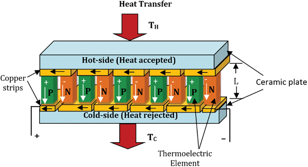
Figure 1: A typical TEG structure
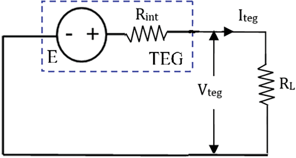
Figure 2: The TEG equivalent circuit
where S denotes the thermocouple material Seebeck coefficient in V/K, the temperature at the hot and cold sides are given as TH and TC in K, respectively the load and thermocouple internal resistances are represented as RL and Rint in Ω, respectively. In the present study, the well-known TEG is based on bismuth telluride (Bi2Te3), and its design parameters are given in Table 1. The Seebeck coefficient value with respect to temperature and the electrical performance of the Bi2Te3 type TEG are illustrated in Figs. 3–5, respectively.
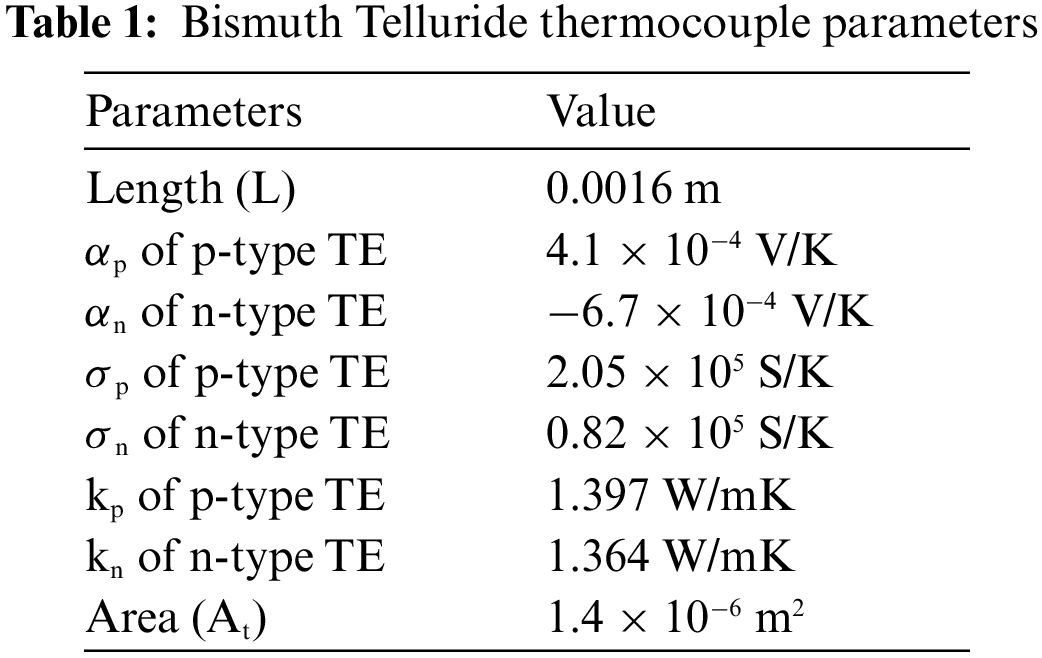
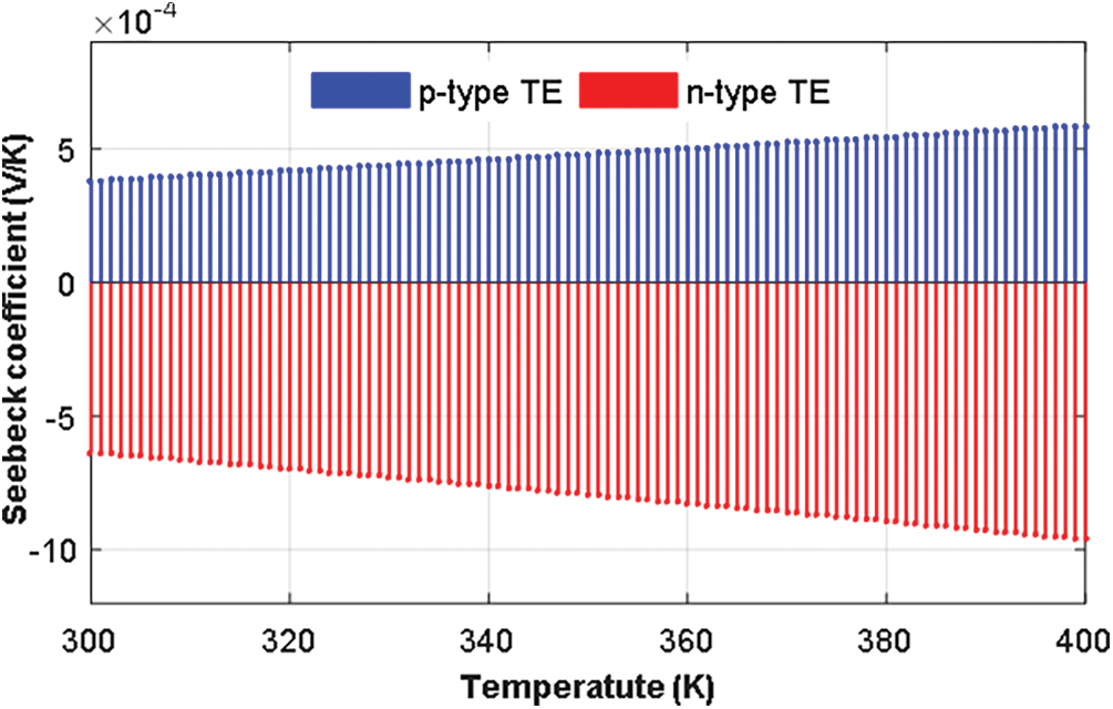
Figure 3: The Seebeck coefficient of Bi2Te3 thermocouple
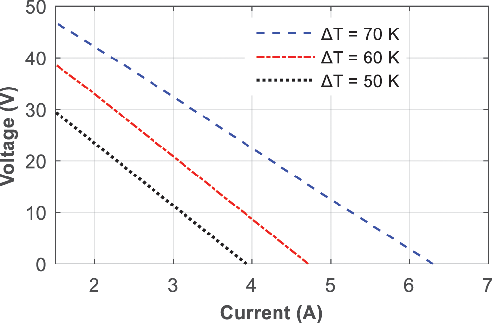
Figure 4: The voltage vs. current relationship of the TEG model
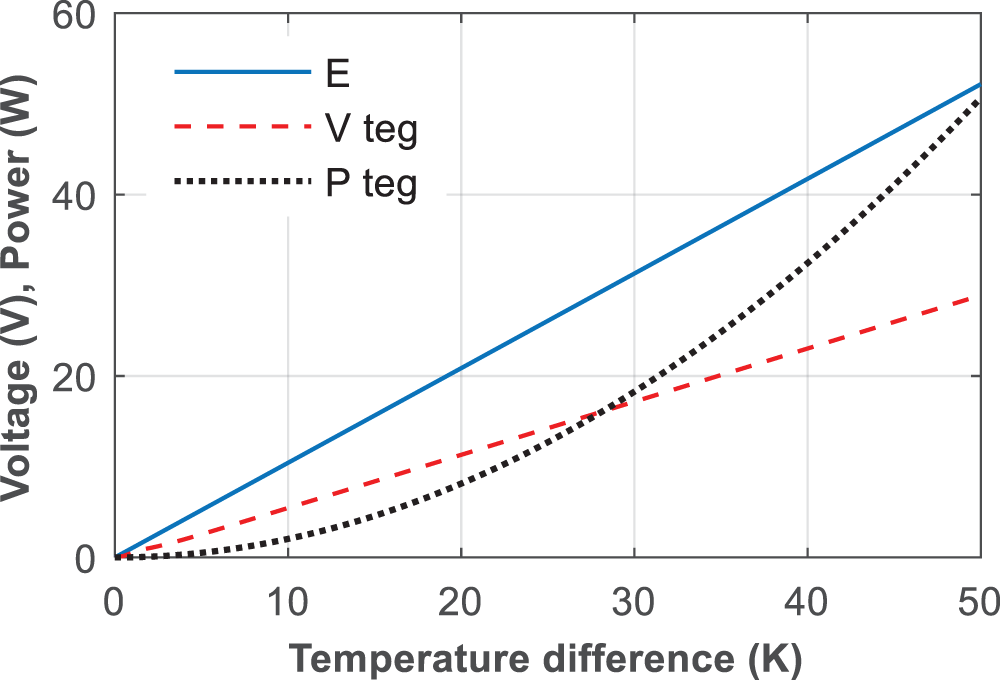
Figure 5: Electrical performance of the TEG model
3 Proposed MPPT Control Algorithm
The MPPT is used to extract the maximum power from the renewable energy source by setting certain electrical parameters correctly. In this study, the combined P&O and FLC control is chosen to achieve the MPP quickly and accurately. The MPP tracking using conventional P&O technique usually has more variation in the output voltage even after the system reaches the MPP. In recent years, the intelligent algorithm-based MPP trackers are preferred due to their advantages such as fast, accurate and stable output around the MPP [23–27]. Among the various intelligent techniques, the FLC-based MPPT control techniques have been widely preferred due to their advantages for renewable energy systems [28–31]. For the proposed system, the FLC-based P&O tracker is selected, and the change in power (ΔP) and the changes in the power-to-voltage ratio are selected as inputs to the FLC. These inputs are determined based on the P&O method and expressed in the following equations.
The FLC can easily determine the current position of the system operating point and its movement on the power vs. voltage (P-V) curve using the inputs of error (e) and ΔP summarized in the following equations.
Using the inputs, the FLC generates a reference voltage signal Vref. The reference voltage is then compared with a sawtooth wave to generate the switching pulses for the boost converter circuit. The switching pulses generated by the pulse width modulation (PWM) unit change the switching frequency of the boost converter which causes the voltage magnitude of TEG to change and the operating point of TEG to shift toward the peak value on the P-V curve. The flowchart of the FLC-based MPP tracking control algorithm is shown in Fig. 6. In the proposed algorithm, the output power of TEG is calculated from the measured voltage and current. Based on the voltage and power parameters, the error is calculated to perform a control action at any point of time. If the operating point of the system is at the MPP of the P-V curve, the error is zero so the controller does not intervene. Assuming the control error is not zero, which means that the system operating point has not reached the MPP of the P-V curve, the controller adjusts the output voltage of TEG based on the polarity of the control error and the ΔP values, as illustrated in Fig. 6. The controller repeats the process of voltage adjustment until the error becomes zero. The schematic of the proposed MPPT control technique in the MATLAB Simulink environment is illustrated in Fig. 7. At the beginning, the voltage Vteg (k−1) and power Pteg (k−1) are considered as zero. These two parameters are updated with the current value of Vteg and Pteg at the start of the next cycle. The FLC design is explained in the following implementation section.
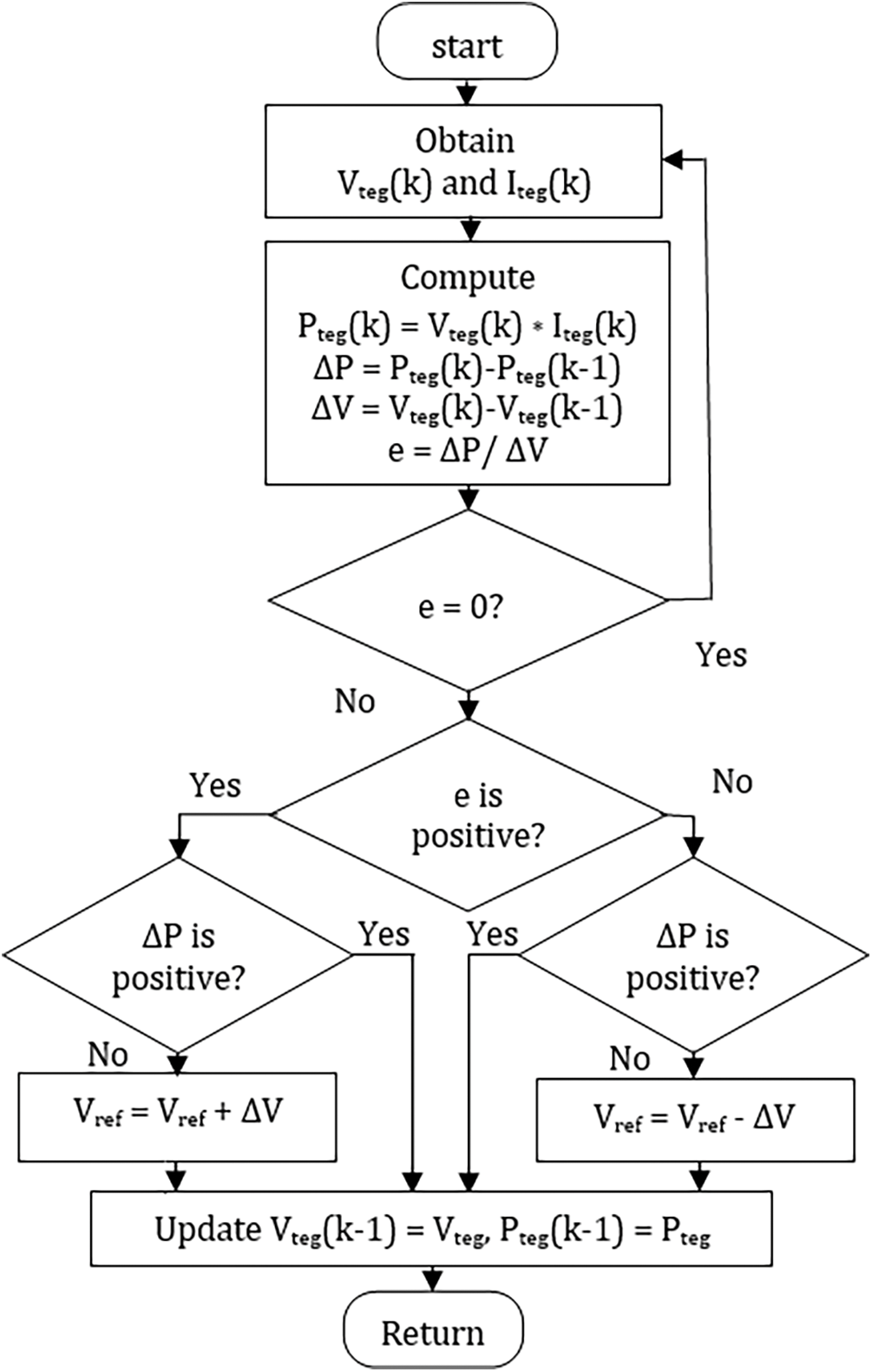
Figure 6: MPPT control algorithm flowchart
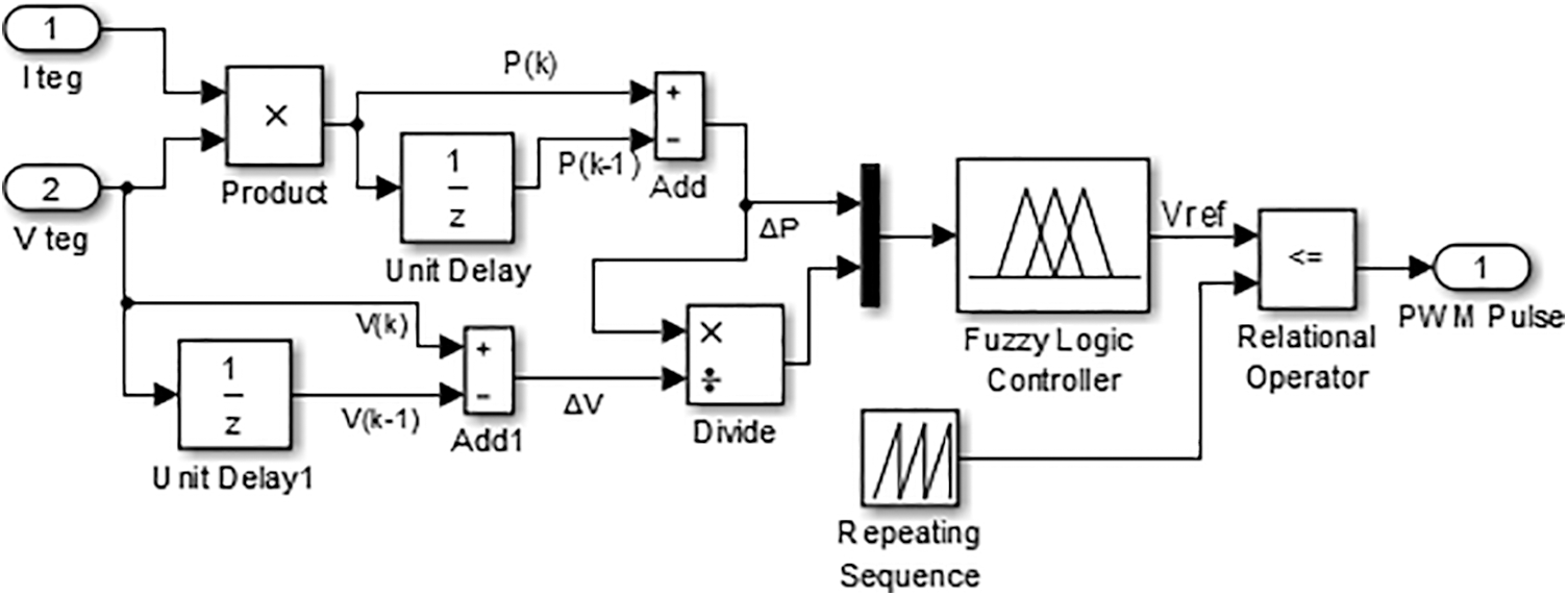
Figure 7: The P&O and FLC combined MPPT control scheme
4 Thermoelectric System Design
Recently, TEGs have attracted more attention as a renewable energy source for converting unused thermal energy or waste heat from various sources such as photovoltaic systems, automobile engines, internal combustion engines, industrial heating processes etc., into usable electricity. TEG is a reliable solid-state technology that can convert freely available thermal energy into electricity with a simple mechanism. In this context, a thermoelectric system with TEG is proposed to convert the thermal energy stored in the hot water tank of the EWH into usable electricity. The schematic of the thermoelectric system is illustrated in Fig. 8, where the temperature of the surface of the hot water tank of EWH t and the ambient temperature are used as the hot and cold sides of TEG, respectively. TEG uses the temperature difference at the input to generate electricity. Ceramic and copper strips are arranged on both sides for effective heat and power conduction. The output of TEG is usually quite low, so amplification is required to achieve sufficient output which can be done by a power electronic circuit [32].
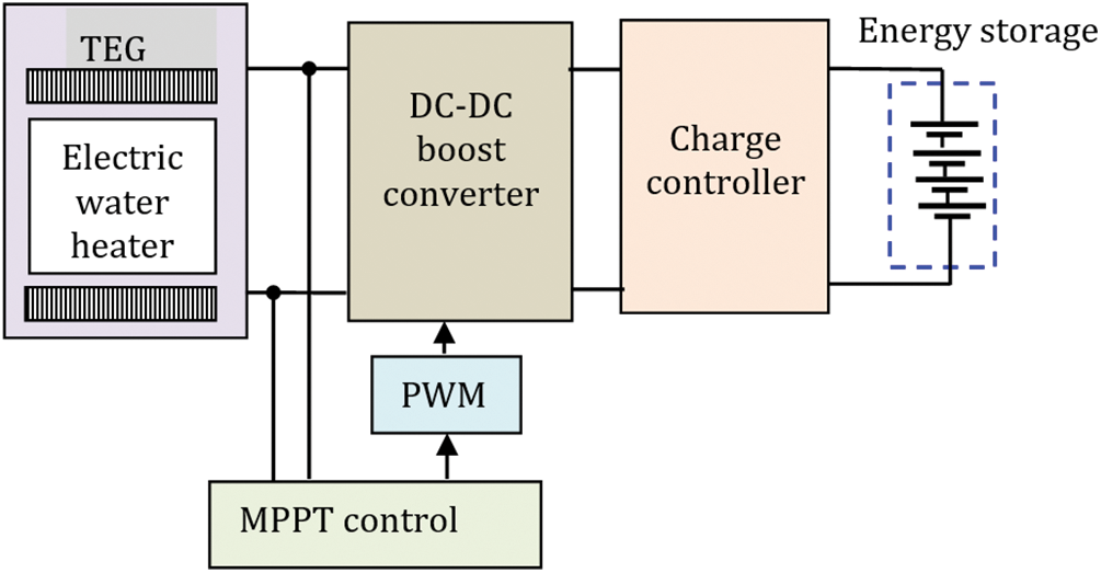
Figure 8: Block diagram of the thermoelectric system
In this paper, a high step-up DC-DC converter circuit with an efficient MPPT control technique is used to maximize the power output of the TEG. The energy generated by the TEG is stored in the battery for use and the charge controller monitor and controls the storage system. The stored energy can be used to provide uninterruptible power supply to low power consumption equipment on the consumer side if the inverter circuit is designed accordingly. By regenerating the electricity from the unused waste heat energy, the consumer obtains additional electrical energy suitable to operate less power-consuming sensitive loads. In addition, the proposed system minimizes energy losses, thereby lowering the electricity tariff.
4.1 Thermoelectric Generator Implementation
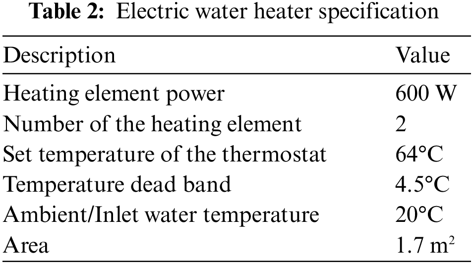
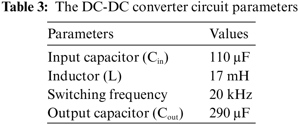
The main objective of the proposed system is to use the unused stored thermal energy of the EWH for additional electricity generation, thus reducing the energy losses and the electricity tariff for the consumers. In the proposed module, the series-connected thermocouples are arranged in a double element type EWH, the cold and hot sides of the TEG attached to the outer surface and the inner hot water tank of the EWH as illustrated in Fig. 9. The copper strip and ceramic plate are arranged at each side of the TEG for better electrical and thermal conductivity. The thermoelectric system implementation for generating electricity is depicted in Fig. 10. The specifications of the EWH are shown in Table 2. The parameters of the DC-DC converter were chosen based on the design procedure suggested in [33], and the parameters of the boost converter circuit in continuous current mode are listed in Table 3. The charge controller confirms battery charging when the TEG generates sufficient power; a lead-acid battery was chosen for this study.
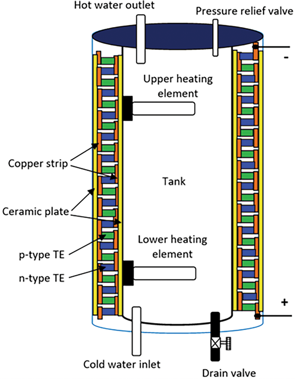
Figure 9: Thermocouples arrangement inside the EWH
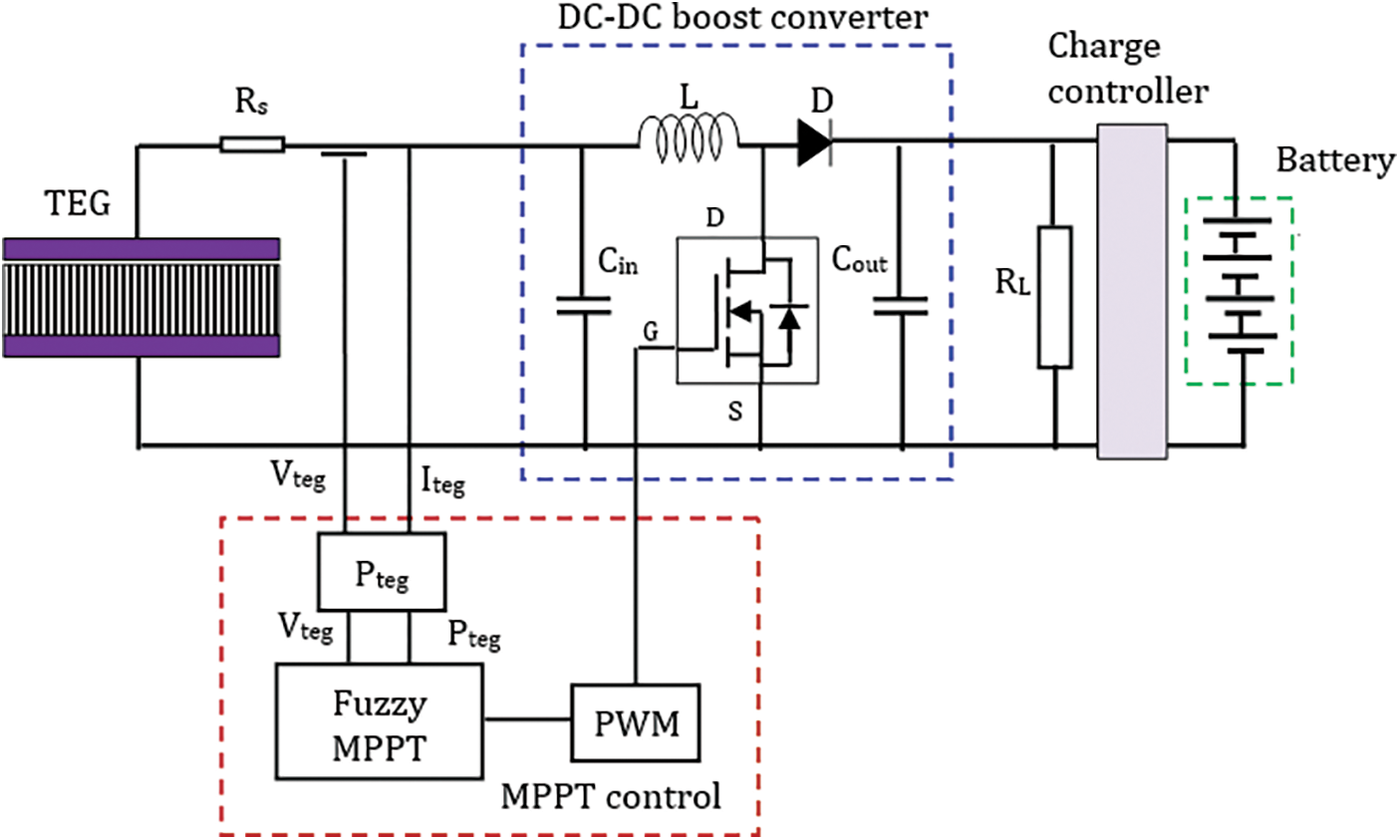
Figure 10: Thermoelectric system overall implementation
5 Implementation of the MPPT Control Scheme
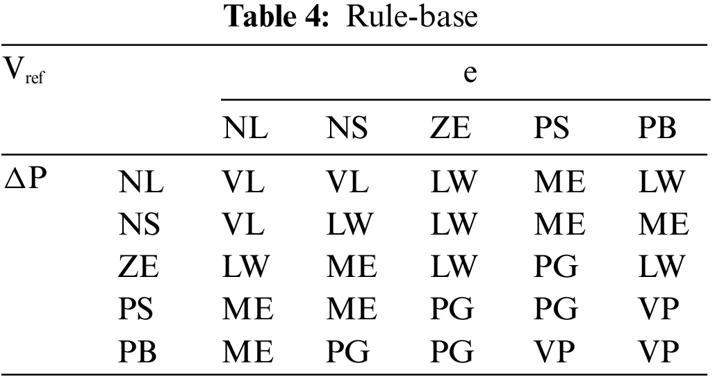
In FLC-based P&O MPPT control, the FLC uses two inputs namely error (5) and change in power (6) to generate a necessary control signal to move the operating point toward MPP. In the design part of the FLC, the inputs are represented by five fuzzy sets with specific linguistic descriptions namely NL: negative large, NS: negative small, ZE: zero, PS: positive small, PB: positive big. Similarly, the output variable is represented as VL: very low, LW: low, ME: medium, PG: big, VP: very big. The shape of the fuzzy sets used for the inputs and output variables of the FLC is shown in Fig. 11. The rule-based is developed for the FLC to move the TEG operating point quickly and accurately toward the MPP on the P-V curve. For instance, the negative error input denotes that the operating point of TEG is currently on the right side of the peak point on the P-V curve, so the voltage of the TEG must be reduced to attain the MPP. The FLC output must be kept at a low level so that the output voltage of TEG can be reduced to reach the MPP. Suppose the error input is positive and ΔP is also positive, the output voltage of TEG must be increased by increasing the output of the fuzzy controller to reach the MPP. Similarly, 25 fuzzy rules are developed, which are shown in Table 4.
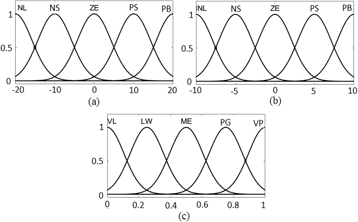
Figure 11: Fuzzy membership function (a) input ‘e’ (b) input ‘ΔP’ (c) output ‘Vref’
6 Simulation Results Analysis and Discussion
The performance of the designed EWH-based thermoelectric system is verified under steady-state and transient conditions, and the results are analyzed to confirm the usefulness of the system for electricity generation using the stored thermal energy of EWH. Based on the area of the EWH, we considered 750 thermocouples in the system for this study. In the first part of the study, the electrical characteristics of the proposed thermoelectric system are investigated by maintaining a stable temperature difference of 50 K between the two sides of the TEG. The electrical performances such as voltage, current and power are recorded for the set temperature difference as shown in Fig. 12. From this result, it can be seen that TEG is able to produce fast and stable results for the varying temperature difference. Moreover, the proposed MPPT method effectively harvests the maximum power from the source for a short period of time and provides a constant output power without any fluctuation.
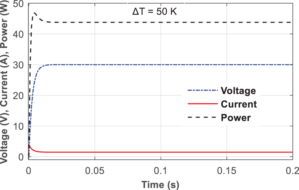
Figure 12: Thermoelectric system performance for the temperature difference of 50°K
A similar behavior is also observed for the current and voltage parameters during this study as can be seen in Fig. 12. Therefore, the proposed thermoelectric system can generate considerable power using the freely available unused thermal energy of the domestic EWH.
The transient performance of the system is verified under varying input temperature conditions. First, step-change in temperature is applied at the hot side of the TEG by keeping a constant temperature of 280°K at the cold side. The electrical output of the system parameters such as voltage, power, current and efficiency for the different temperatures on the hot side are shown in Fig. 13. From the result, the electrical output of the system perfectly follows the changes in temperature on the hot side, the magnitude of all these parameters are varies proportionally with the temperature. The usefulness of the designed model is investigated by the total efficiency of the system which is calculated from the ratio of system output power to the temperature input of TEG. From the efficiency result of Fig. 13c, it is noticed that the system efficiency is better for higher input temperature at the hot side of the TEG. Also, the result demonstrates that the proposed model can produce higher electrical power output for the high temperatures on the hot side as illustrated in Fig. 13a during 0.1 to 0.15 s.
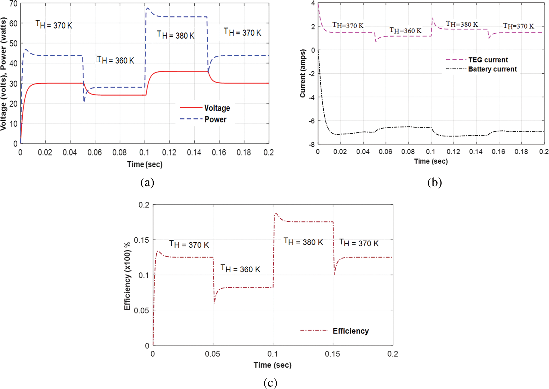
Figure 13: Thermoelectric system response for step-change in temperature at the hot side (TH) (a) voltage and power output (b) TEG and battery current flow (c) system efficiency
The performance of the thermoelectric system under temperature changes is also investigated by continuously changing the temperature difference between the hot and cold sides at different time intervals is in Fig. 14. The result demonstrates that the system outputs are changing accordingly to input which confirms the dynamic response of the proposed model.
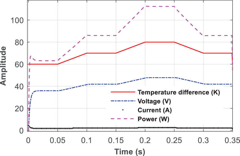
Figure 14: Thermoelectric system performance for varying temperature differences
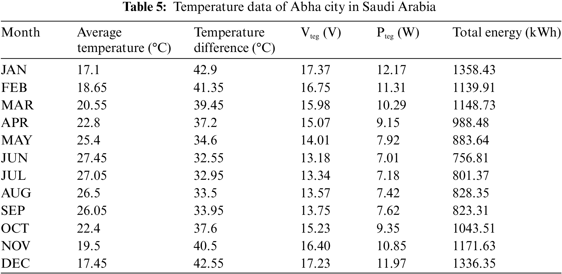
To demonstrate the feasibility of the proposed thermoelectric system for real-time implementation, the temperature data of Abha city [34] in Saudi Arabia was used for the analysis. The monthly average temperature value of 2020 was used for this analysis (see Table 5). The temperature difference is determined by assuming a temperature value of 60°C on the hot side. Also, the load resistance (RL) is chosen as the same value as Rint, while calculating the possible voltage and power output from the system. The power output of the TEG is directly proportional to the difference in temperature across the cold and hot sides, when the temperature difference is higher, the electricity generation is greater. From Table 5, it can be seen that in the months of December, January and February, the temperature difference is higher, which causes the system to generate a larger voltage and power. The temperature on the cold side of the TEG is low in the winter season, resulting in a higher temperature difference and therefore higher power generation.
The possible voltage, power, and energy outputs of the system as a function of temperature difference are illustrated in Fig. 15. Similarly, the probable energy generation with the proposed thermoelectric system is depicted in Fig. 16. From Fig. 16, it is noticed that during the winter season the system can generate a significant amount of electricity for the households during the winter season, which could reduce the energy consumption and peak hour electricity demand from the power grid. The analysis of the real-time data also clearly shows that by implementing the proposed system during the winter season, the residential customers will get a benefit from the electricity tariff for almost1200 kWh of energy consumption.
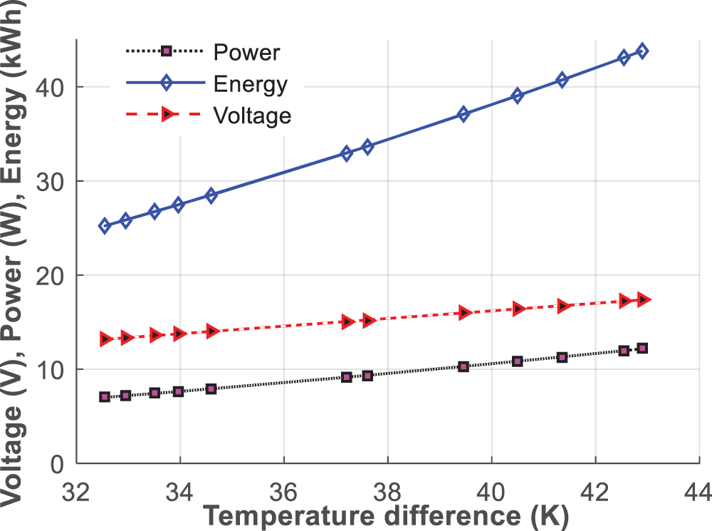
Figure 15: Electrical output based on the Abha city temperature data
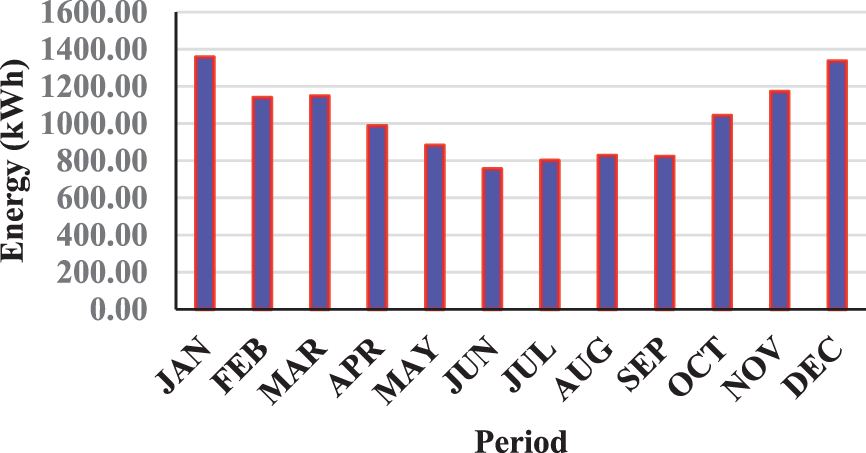
Figure 16: Monthly energy statistics based on the Abha city temperature data
An efficient FLC and P&O combined MPPT control algorithm was investigated for the domestic EWH-based thermoelectric power generation system. The system was designed using TEG with thermocouples connected in series to generate electricity from the freely available thermal energy of the domestic EWH. The control algorithm proposed in the present study effectively controls the switching frequency of the boost converter in the present system to continuously harvest the possible maximum power from the TEG. The study results confirmed that the designed model can generate adequate electrical power to charge the battery-based energy storage unit, thereby supplying power to various low-power-electrical loads in the household. In addition, the performance of the designed system was tested under steady-state and transient conditions with different input temperatures to confirm its effectiveness. The test results showed that the present system is capable of generating stable electrical power under different environmental conditions. To ensure the feasibility of real-time implementation, the temperature data of Abha city in Saudi Arabia was used to analyze the proposed system model. The study report shows that the proposed thermoelectric system can generate a significant amount of electrical power during the winter season. The implementation of the proposed system can benefit the domestic electricity consumers and reduce the electricity cost for grid connection. In addition, analysis of real-time data confirms that approximately 1200 kWh of electrical energy can be generated each month during the winter season.
Funding Statement: The authors extend their appreciation to the Deputyship for Research & Innovation, Ministry of Education in Saudi Arabia for funding this research work through the project number (IF2-PSAU/2022/01/22797).
Conflicts of Interest: The authors declare that they have no conflicts of interest to report regarding the present study.
References
1. Energy Cost Calculator for Electric and Gas Water Heaters, “U.S. Department of Energy,” 2015. [Online]. Available: http://energy.gov/eere/femp/energy-cost-calculator-electric-and-gaswater-heaters-0#o [Google Scholar]
2. X. Sheng, C. Liuchen, C. Bo, Y. He and Z. Chaolong, “A novel domestic electric water heater control method,” IEEE Transactions on Smart Grid, vol. 11, no. 4, pp. 3246–3256, 2020. [Google Scholar]
3. M. H. Nehrir, B. J. LaMeres and Gerez, “A customer-interactive electric water heater demand-side management strategy using fuzzy logic,” in Proc. Int. Conf. IEEE Power Eng. Soc. Winter Meeting, New York, USA, vol. 1, pp. 433–436, 1999. [Google Scholar]
4. International Energy Agency. 2018. [Online]. Available: https://www.iea.org/policiesandmeasures/renewableene [Google Scholar]
5. F. Ruelens, B. J. Claessens, S. Quaiyum, B. De Schutter, R. Babuška et al., “Reinforcement learning applied to an electric water heater: From theory to practice,” IEEE Transactions on Smart Grid, vol. 9, no. 4, pp. 3792–3800, 2018. [Google Scholar]
6. K. Vanthournout, R. D’hulst, D. Geysen and G. Jacobs, “A smart domestic hot water buffer,” IEEE Transactions on Smart Grid, vol. 3, no. 4, pp. 2121–2127, 2012. [Google Scholar]
7. H. W. Zhang and Y. Zhou, “Intelligent under frequency and under voltage load shedding method based on the active participation of smart appliances,” IEEE Transactions on Smart Grid, vol. 8, no. 1, pp. 353–361, 2017. [Google Scholar]
8. C. Perfumo, E. Kofman, J. H. Braslavsky and J. K. Ward, “Load management: Model-based control of aggregate power for populations of thermostatically controlled loads,” Energy Conversion and Management, vol. 55, no. 1, pp. 36–48, 2012. [Google Scholar]
9. R. Diao, S. L. Elizondo, E. Mayhorn, Y. Zhang and N. Samaan, “Electric water heater modeling and control strategies for demand response,” in Proc. Int. Conf. IEEE Power Energy Soc. Gen. Meeting, San Diego, California, USA, pp. 1–8, 2012. [Google Scholar]
10. E. McKenna and M. Thomson, “High-resolution stochastic integrated thermal-electrical domestic demand model,” Applied Energy, vol. 165, no. 7, pp. 445–461, 2016. [Google Scholar]
11. A. Moreau, “Control strategy for domestic water heaters during peak periods and its impact on the demand for electricity,” Energy Procedia, vol. 12, pp. 1074–1082, 2011. [Google Scholar]
12. J. Chen, J. Klein, S. Wu, R. Flammang, M. Heibel et al., “A thermoelectric energy harvesting system for powering wireless sensors in nuclear power plants,” IEEE Transactions on Nuclear Science, vol. 63, no. 5, pp. 2738–2746, 2016. [Google Scholar]
13. A. Roy, A. Klinefelter, F. B. Yahya, X. Chen, L. P. Gonzalez-Guerrero et al., “A 6.45 μW self-powered SoC with integrated energy harvesting power management and ULP asymmetric radios for portable biomedical systems,” IEEE Transactions on Biomedical Circuits and Systems, vol. 9, no. 6, pp. 862–874, 2015. [Google Scholar] [PubMed]
14. P. C. Dias, F. J. O. Morais, M. B. de Morais França, E. C. Ferreira, A. Cabotet et al., “Autonomous multi-sensor system powered by a solar thermoelectric energy harvester with ultralow-power management circuit,” IEEE Transactions on Instrumentation and Measurement, vol. 64, no. 11, pp. 2918–2925, 2015. [Google Scholar]
15. A. Montecucco and A. R. Knox, “Maximum power point tracking converter based on the open-circuit voltage method for thermoelectric generators,” IEEE Transactions on Power Electronics, vol. 30, no. 2, pp. 828–839, 2015. [Google Scholar]
16. G. Pennelli, E. Dimaggio and M. Macucci, “Electrical and thermal optimization of energy-conversion systems based on thermoelectric generators,” Energy, vol. 240, no. 1, pp. 122494, 2022. [Google Scholar]
17. N. Kanagaraj and M. Al-Alansi, “Maximum power extraction control algorithm for hybrid renewable energy system,” Computer Systems Science & Engineering, vol. 45, no. 1, pp. 769–783, 2023. [Google Scholar]
18. J. Vega and J. Lezama, “Design and implementation of a thermoelectric energy harvester with MPPT algorithms and supercapacitor,” IEEE Latin America Transactions, vol. 19, no. 1, pp. 163–170, 2021. [Google Scholar]
19. I. Laird and D. Lu, “High step-up DC/DC topology and MPPT algorithm for use with a thermoelectric generator,” IEEE Transactions on Power Electronics, vol. 28, no. 7, pp. 3147–3157, 2013. [Google Scholar]
20. N. Kanagaraj, “Photovoltaic and thermoelectric generator combined hybrid energy system with an enhanced maximum power point tracking technique for higher energy conversion efficiency,” Sustainability, vol. 16, no. 6, pp. 3144, 2021. [Google Scholar]
21. H. O. Tabrizi, H. M. P. C. Jayaweera and A. Muhtaroğlu, “Fully integrated autonomous interface with maximum power point tracking for energy harvesting tegs with high power capacity,” IEEE Transactions on Power Electronics, vol. 35, no. 5, pp. 4905–4914, 2020. [Google Scholar]
22. J. H. Meng, X. X. Zhang and X. D. Wang, “Characteristics analysis and parametric study of a thermoelectric generator by considering variable material properties and heat losses,” International Journal of Heat and Mass Transfer, vol. 80, pp. 227–235, 2015. [Google Scholar]
23. R. Kim, J. Lai, B. York and A. Koran, “Analysis and design of maximum power point tracking scheme for thermoelectric battery energy storage system,” IEEE Transactions on Industrial Electronics, vol. 56, no. 9, pp. 3709–3716, 2009. [Google Scholar]
24. S. C. Chandrarathna and J. Lee, “A dual-stage boost converter using two-dimensional adaptive input-sampling MPPT for thermoelectric energy harvesting,” IEEE Transactions on Circuits and Systems I: Regular Papers, vol. 66, no. 12, pp. 4888–4900, 2019. [Google Scholar]
25. M. Bond and J. Park, “Current-sensor less power estimation and MPPT implementation for thermoelectric generators,” IEEE Transactions on Industrial Electronics, vol. 62, no. 9, pp. 5539–5548, 2015. [Google Scholar]
26. J. Kim and C. Kim, “A DC-DC boost converter with variation-tolerant MPPT technique and efficient ZCS circuit for thermoelectric energy harvesting applications,” IEEE Transactions on Power Electronics, vol. 28, no. 8, pp. 3827–3833, 2013. [Google Scholar]
27. B. Bijukumar, A. G. K. Raam, S. I. Ganesan and C. Nagamani, “A linear extrapolation-based MPPT algorithm for thermoelectric generators under dynamically varying temperature conditions,” IEEE Transactions on Energy Conversion, vol. 33, no. 4, pp. 1641–1649, 2018. [Google Scholar]
28. A. Chouksey, S. Awasthi and S. K. Singh, “Fuzzy cognitive network-based maximum power point tracking using a self-tuned adaptive gain scheduled fuzzy proportional integral derivative controller and improved artificial neural network-based particle swarm optimization,” Fuzzy Sets and Systems, vol. 381, no. 3, pp. 26–50, 2020. [Google Scholar]
29. N. Kanagaraj, “An enhanced maximum power point tracking method for thermoelectric generator using adaptive neuro-fuzzy inference system,” Journal of Electrical Engineering & Technology, vol. 16, no. 3, pp. 1207–1218, 2021. [Google Scholar]
30. Y. Li, S. Samad, F. W. Ahmed, S. S. Abdulkareem, S. Hao et al., “Analysis and enhancement of PV efficiency with hybrid MSFLA-FLC MPPT method under different environmental conditions,” Journal of Cleaner Production, vol. 271, no. 3, pp. 122195, 2020. [Google Scholar]
31. S. Farajdadian and S. H. Hosseini, “Design of an optimal fuzzy controller to obtain maximum power in solar power generation system,” Solar Energy, vol. 182, no. 1, pp. 161–178, 2019. [Google Scholar]
32. N. Young-Seok, S. Jeong-Il, K. Hyun-Sik and L. Sang-Gug, “A reconfigurable DC-DC converter for maximum thermoelectric energy harvesting in a battery-powered duty-cycling wireless sensor node,” IEEE Journal of Solid-State Circuits, vol. 57, no. 9, pp. 2719–2730, 2022. [Google Scholar]
33. N. Kanagaraj and H. Rezk, “Dynamic voltage restorer integrated with photovoltaic-thermoelectric generator for voltage disturbances compensation and energy saving in three-phase system,” Sustainability, vol. 13, no. 6, pp. 3511, 2021. [Google Scholar]
34. Climate and Monthly Weather Forecast Abha, Saudi Arabia, “Weather Atlas,” 2020. [Online]. Available: https://www.weather-atlas.com/en/saudi-arabia/abha-climate [Google Scholar]
Cite This Article
 Copyright © 2023 The Author(s). Published by Tech Science Press.
This work is licensed under a Creative Commons Attribution 4.0 International License , which permits unrestricted use, distribution, and reproduction in any medium, provided the original work is properly cited.
 Downloads
 Citation Tools