
 Submit a Paper
 Propose a Special lssue
 Open Access
ARTICLE

Dynamic Modeling and Sensitivity Analysis for an MEA-Based CO2 Capture Absorber
1 Ningbo University of Finance and Economics, Ningbo, 315175, China
2 Huzhou University, Huzhou, 313000, China
3 Key Laboratory of Intelligent Manufacturing Quality Big Data Tracing and Analysis of Zhejiang Province, China Jiliang University, Hangzhou, 310018, China
4 Ningbotech University, Ningbo, 315100, China
* Corresponding Author: Lingjian Ye. Email:
Intelligent Automation & Soft Computing 2023, 36(3), 3535-3550. https://doi.org/10.32604/iasc.2023.036399
Received 29 September 2022; Accepted 06 December 2022; Issue published 15 March 2023
 View Full Text
 Download PDF
Abstract
The absorber is the key unit in the post-combustion monoethanolamine (MEA)-based carbon dioxide (CO2) capture process. A rate-based dynamic model for the absorber is developed and validated using steady-state experimental data reported in open literature. Sensitivity analysis is performed with respect to important model parameters associated with the reaction, mass transport and physical property relationships. Then, a singular value decomposition (SVD)-based subspace parameter estimation method is proposed to improve the model accuracy. Finally, dynamic simulations are carried out to investigate the effects of the feed rate of lean MEA solution and the flue inlet conditions. Simulation results indicate that the established dynamic model can reasonably reflect the physical behavior of the absorber. Some new insights are gained from the simulation results.Keywords
Combustion-based generation is a main way for electricity generation, and it will continue to domain the market for a long time. Post-combustion flue gas from either the natural gas or coal contains high content carbon dioxide (CO2), which is the main source of the greenhouse effect and is detrimental to the global climate. Post-combustion carbon capture process is to capture the CO2 contained within the flue gas, such that the electricity generation process can fulfill the environmental regulations. Since the post-combustion design can be carried out by retrofitting the existing facilities, such a process can substantially extend the lifetime of combustion-based generation plants, which are of low investments and operational costs. Among various feasible techniques, chemical absorption using the monoethanolamine (MEA) is considered as the most suitable scheme for the commercialization of the CO2 capture process. Compared with other chemical absorbers, MEA has a high absorption ability, chemical stability and is easy to regenerate, thus widely adopted in practice.
The post-combustion CO2 capture plant is illustrated in Fig. 1, which includes an absorber tower, a heat exchanger, and a regeneration tower. Flue gas from the upper stream (main components: CO2, H2O, O2 and N2) is fed in to the bottom of the absorber, where the CO2 reacts with the MEA aqueous solution flowing from the top to bottom. The CO2 is transferred from the gas to liquid, and the clean gas leaves from top of the absorber into the atmosphere. The absorbed CO2 is in the form of MEACOO- and HCO3- in the MEA solution, which is discharged from the bottom. The rich solution passes through the heat exchanger and is finally fed into the regenerator. In the regenerator, the CO2 is released into the gas under a high operating temperature. The released high content CO2 gas leaves at the top of the regenerator, and is condensed and stored. The regenerated MEA solution leaves from the bottom and passes through the heat exchanger to preheat the cold rich MEA solution. In the tank, the MEA is made up to certain loading, then is again pumped into the absorber for continuous operations.
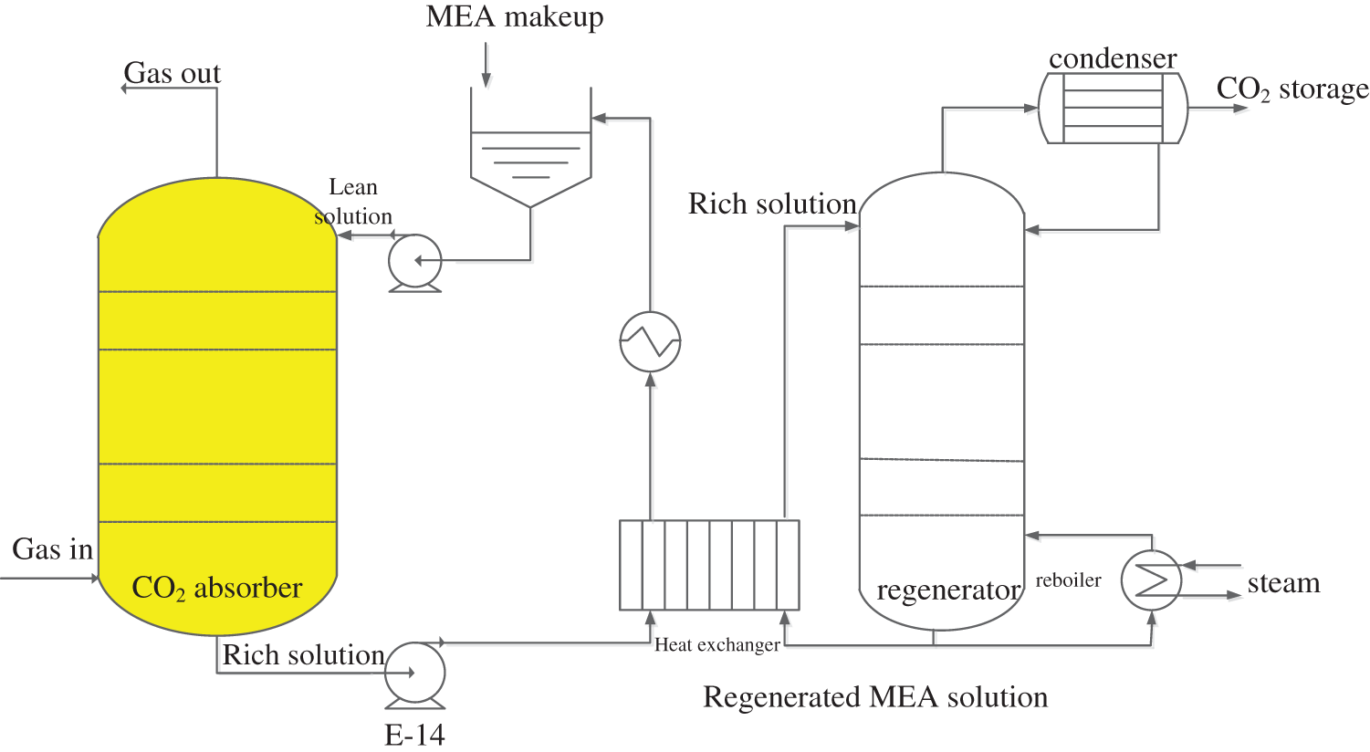
Figure 1: Post-combustion MEA-based CO2 capture process
The absorber is the most important operating unit, which directly determines the CO2 capture quality and the plant efficiency. Compared with experimental studies, simulation is often more flexible and of lower costs, thus it has become a popular way to investigate the principle of operating the absorber. Mathematical modeling for the absorber has attracted a lot of attention from the research community. To model the absorber, the chemical reactions between CO2 and MEA solution and the mass transfer of CO2 are the two key elements of the CO2 capture process, which should be accurately characterized to establish the mathematical relationships. Based on different levels of assumptions and approximations, Kenig et al. [1] summarized the following five levels of modeling for the absorbing reaction process:
1: equilibrium stage + reaction equilibrium;
2: equilibrium + reaction kinetics;
3: rate-based approach + reaction equilibrium;
4: rate-based approach + reaction kinetics + enhancement factor;
5: rate-based approach + reaction kinetics + film reactions + electrolytes.
Equilibrium stage is the traditional theoretical plate theory, assuming the vapor-liquid equilibrium at a plate. In practical situations which cannot attain equilibrium, the transfer efficiency is often introduced to compensate the errors. However, the usage of transfer efficiency is still restrictive. Alternatively, the rate-based approach is more suitable to describe the true process, thus has been becoming prevalent in the recent year [2–6]. For mass transfer with occurring chemical reactions, there are three common models: two-film model, penetration model and surface renewal model. The two-film model is the most classical one describing the vapor-liquid mass transfer phenomenon, where two thin films are assumed present in the contacting surfaces and equilibrium is attained at their boundary. All of the three are approximations for the mass transfer phenomenon, by using algebraic equations to simply the partial dynamic equations, thus are numerically easier to solve. The enhancement factor is typically introduced to measure the influence of chemical reactions on the mass transfer effect. The calculation of the enhancement factor is therefore crucial. Recently, Putta et al. [7] summarized and compared 24 different models for the calculation of the enhancement factor, using the MEA-based CO2 absorption as a case study. The results showed that the ones given by [8–10] perform the best.
Besides, important factors influencing the mass transfer include gas and liquid physical property models, interfacial area model, reaction kinetics, hydraulic model, and so on. These sub-models are interacting, depend on diverse physical properties. In literatures, there have been reported various sub-models for modeling of the CO2 capture absorber. Wang’s research group reported dynamic models for the absorber and the whole CO2 capture process (levels 3 and 5), using the gPROMS software [2,3]. Kvamsdal et al. [4] and Flo et al. [5,6] used Matlab to simulate the absorber and the entire capture process with model validations (level 4). Posch et al. [11] built a dynamic model using the Aspen Custom Modeler (level 5), the influences of inlet flue federate and lean temperature were studied. Walters et al. [12] established the control-oriented simplified dynamic model. Recently, the Bhattacharyya’s group reported their research works on the thermodynamic model [13], mass transfer model and hydraulic model [14]. The models were calibrated by experimental data. Based on these results, steady state models were presented for the whole capture process [15,16]. All the above mentioned models have different assumptions, calculation methods for the physical properties and reactions, and the model parameters were fitted using different experimental data sets. In general, they have different levels of accuracy and are applicable to specific scenarios. To date, experimental data, especially the dynamic data are rare in the open publications, how to develop simple yet accurate models for the CO2 capture process is still open.
This paper considers dynamic modeling for the CO2 absorber, a level-5 model is established using newly reported mechanical sub-models for the absorber. Section 2 introduces some basic assumptions, then the main modeling equations are described and physical properties are summarized. Sensitivity analysis is carried out in Section 3 for some important model parameters, followed by model calibration to improve the model accuracy. A new singular value decomposition (SVD)-based subspace parameter estimation method is proposed for parameter identification. Finally, dynamic simulations are carried out to study the influences of changing input conditions.
2 Dynamic Modeling for the Absorber
The following assumptions are assumed for developing the dynamic models of the absorber:
(1) The absorber is a 1D plug flow reactor;
(2) The gas components are CO2, H2O, O2 and N2, MEA only exists in the liquid (low volatility);
(3) Linear pressure drop along the column, where the gas pressure at outlet is 1 atm;
(4) Ideal gas equations apply for the gas phase;
(5) Mass transfer is described by the two-film theory, where gas-liquid equilibrium occurs at the film interface;
(6) Chemical reactions occur within the liquid film, whose influence on the mass transfer is represented by enhancement factor.
2.1 Mass and Energy Balance Equations
The mass balance equations for the gas and liquid are given in (1) and (2) as follows [4]:
where hV and hL are the holdups for the vapor and liquid; C, u, N are the mole concentration, velocity and mass transfer rate; superscripts V and L stand for variables associated with the gas and liquid phase, respectively; t and z are the time and height variables; The velocity of gas varies along the column, whilst the velocity of incompressible liquid is regardless of the height.
The energy balance equations are given in (3) and (4) as follows [4]:
where T, Cp, hheat and ae are the temperature, heat capacity, heat transfer coefficient and vapor-liquid interfacial area, respectively;
2.2 Chemical Reactions and Mass Transfer
There is a number of chemical reactions occurring between the CO2 and MEA solution. The following two reversible reactions can well represent the overall reaction process [13]:
Due to the fast occurring reactions, (5) and (6) can be regarded as taking place only within the liquid film, while the chemical components attain equilibrium in the liquid bulk. The reaction constants
The mass transfer is characterized by using the two-film theory (Fig. 2) in (7) [16]:
where
where
where krx and
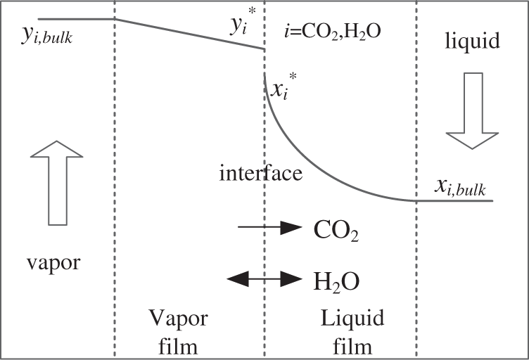
Figure 2: The two-film model
Gaspar et al. [10] recently proposed an improved general method (GM) algorithm, converting the partial differentiable equations into algebraic equations which are relatively easier to solve. For the CO2-H2O-MEA system, the GM solves the following simultaneous equations to compute the enhancement factor E [16]:
where, in the above Eqs. (11)–(17), E and
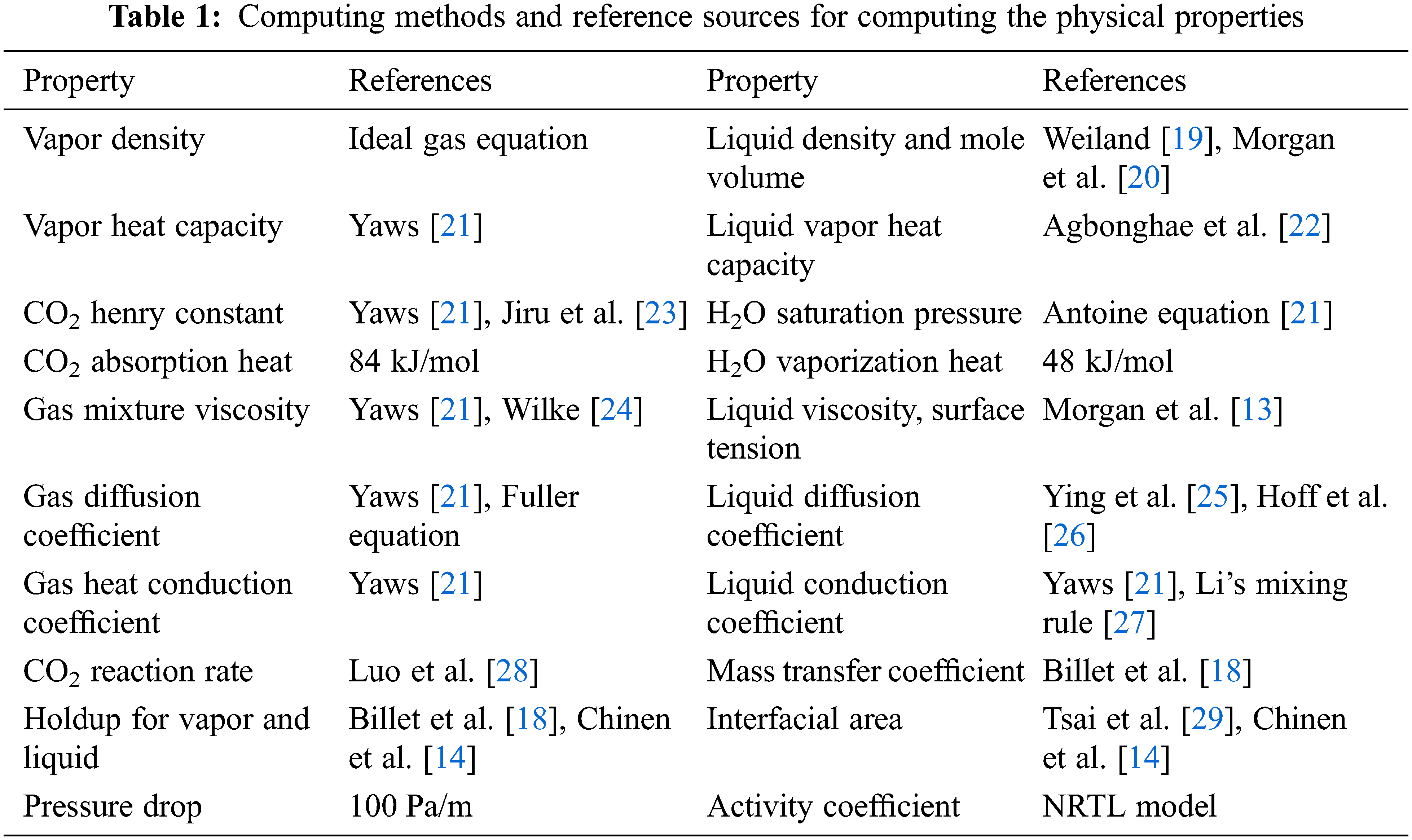
A number of parameters are involved in the above model equations, including: the basic physical properties, thermodynamic parameters, mass transfer rate coefficients, hydraulic parameters, and so on. Table 1 lists a summary of computing relationships with reference sources. In Table 1, the viscosities and surface tensions are used for the computations of holdups and the interfacial area. The geometric parameters are for the packings Mellapak 250Y and MellapakPlus 252Y, which are structurally similar. The computations of the holdup and interfacial area are largely different for different types of packing [18].
3 Model Calibration and Sensitivity Analysis
The above dynamic models are established in Matlab R2017b. The partial differential Eqs. (1)–(4) are solved numerically, where the spatial variables are discretized via finite differences, temporal state variables are solved using the classical four-order Runge-Kutta method. In the case of investigating the steady state results, the differential terms on the left-hand-side of (1)–(4) are set as 0, which are then treated as equality equations.
Due to the complexity and high cost of carrying out experiments on pilot plants, there still lack sufficient dynamic experimental data in open publications for dynamic model validations. In most cases, some steady state data are used for testing purpose.
In this paper, we use the experimental data reported in [17]. The laboratory pilot-plant absorber is of 15 cm diameter, 4.36 m height, with a packing of Mellapak 250Y. The inlet MEA concentration is 30% by weight, while other inlet conditions such as loading and flow rate are different as conducted in the experiments. 20 groups of experimental data were collected covering different operating conditions, including different gas/liquid inlet feed rates, inlet CO2 compositions, inlet gas and liquid temperatures, lean loading, as shown in Table 2. The results are compared with the developed model in this paper, as summarized in Table 3 and plotted in Fig. 3 (black scatters). It can be seen that the trends of outputs of the absorber are correctly estimated. On the other hand, there are some discrepancies under certain operating conditions, the possible reasons include the following:
1) Information contained in the experimental data is incomplete and may be inaccurate. The measurements used in the experiments were analyzed by diverse sensors and different analytical methods, which contain substantial measurement noise. In addition, the H2O content in the inlet gas has not been measured, which has a great impact on the mass and energy balance for the absorber. In the model calculations, they are computed as the saturated H2O pressure corresponding to the pure water. Furthermore, the CO2 content was measured in the dry condition, which further introduces uncertainties.
2) Different physical property model, mass transfer model, heat transfer model and chemical reaction model reported in literatures are adopted, which were developed under different conditions from the experiments in [17]. Such errors can be reduced by model calibration through parameter identifications.
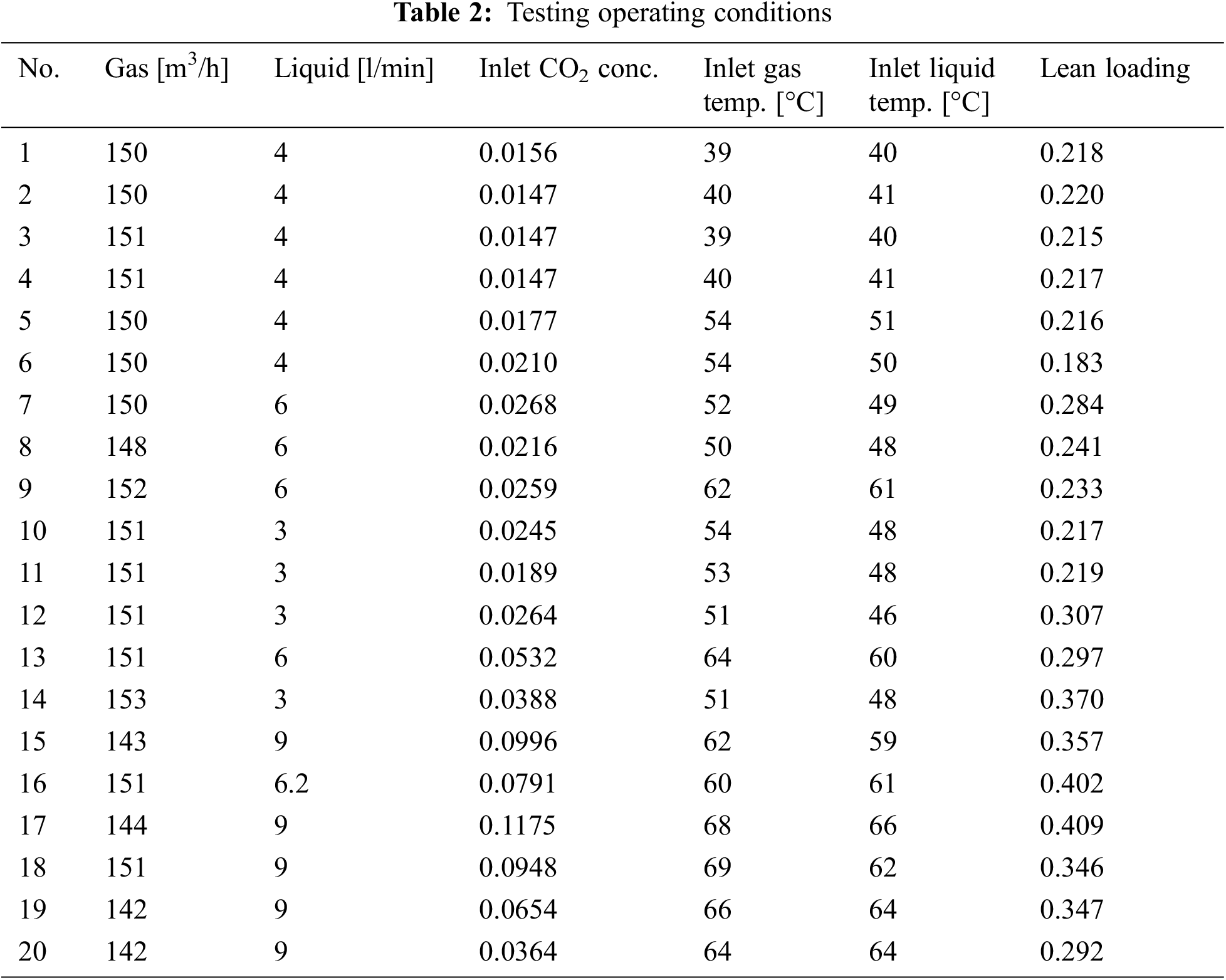
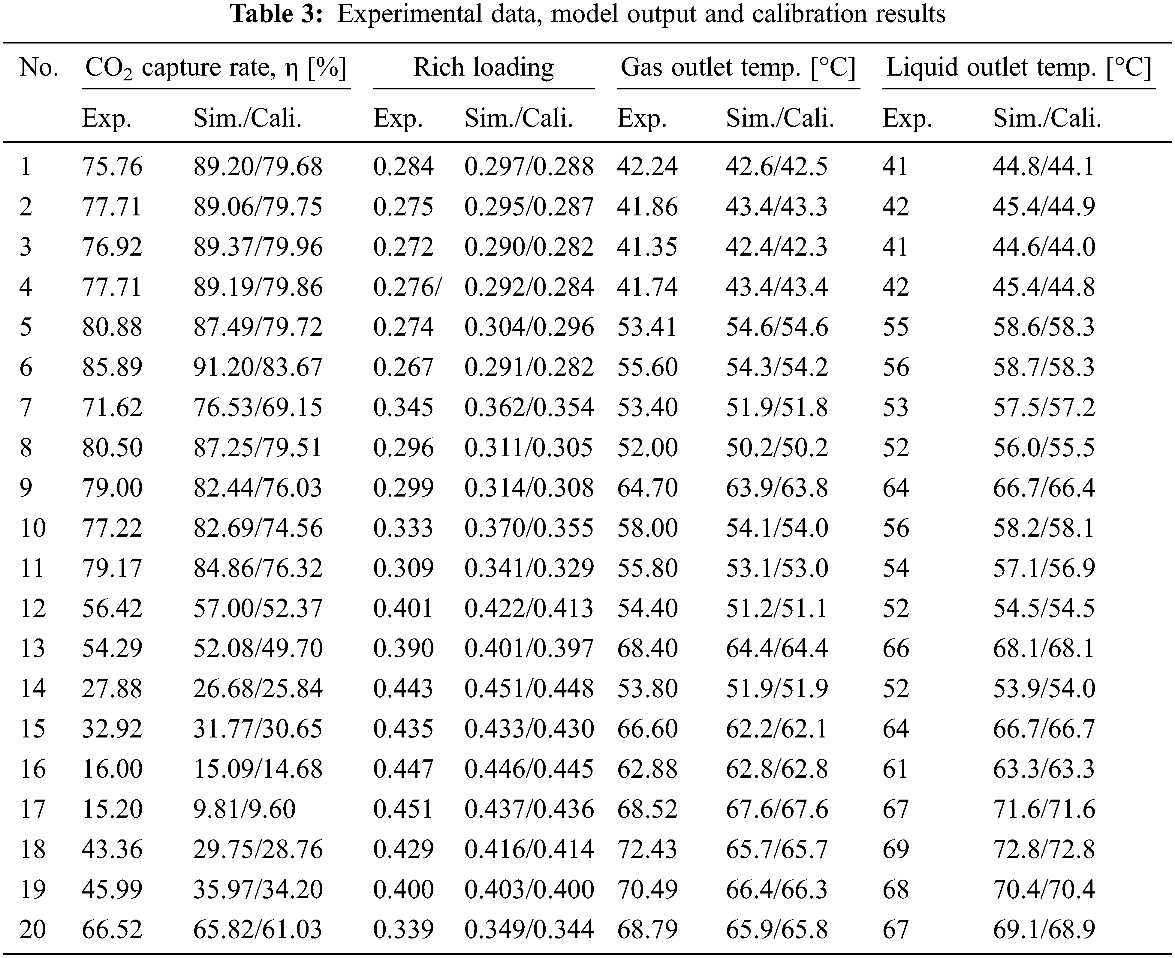
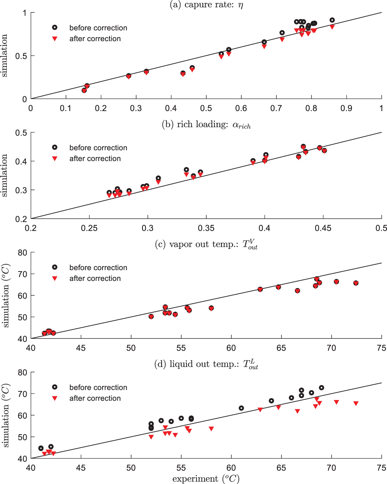
Figure 3: Comparisons between experimental data and simulations results (before and after calibration)
3.2 Sensitivity Analysis and Model Calibration
The most important influencing the absorber’s behavior is the mass transfer, heat transfer and chemical reactions, the following equations are concerned as given in (18)–(21):
1) Interfacial area ae [29]:
2) Vapor mass transfer coefficient kv [18]
3) Liquid mass transfer coefficient kL [18]
4) CO2 reaction rate [28]
5) CO2 absorption heat ΔHabs (reference value: −84 kJ/mol) [16]
In the above equations, 9 crucial parameters are X: = [A1 A2 CV CL k1 E1 k2 E2 ΔHabs]T, whose reference nominal values are listed in Table 4. Sensitivity analysis [30] is performed for these parameters, respectively, by perturbing 10% of their reference values. The model outputs Y: = [η αrich TVout TLout]T are computed and compared. For the ease of observation, Fig. 4 visualizes the 4 × 9 dimensional sensitivity matrix with different sizes and colors, according to the magnitudes of elements. It can be intuitively observed that parameter X6 (E1) has the largest impact on Y1 (η), followed by X1 (A1) on Y1(η), and X6 (E1) on Y2 (αrich). On the contrary, Y3 (TVout) and Y4 (TLout) are less influenced by the model parameters. Intrinsically, these variables are more sensitive to energy relationships, relating closely to the H2O content in the inlet gas, which is however not measured in the experiments.
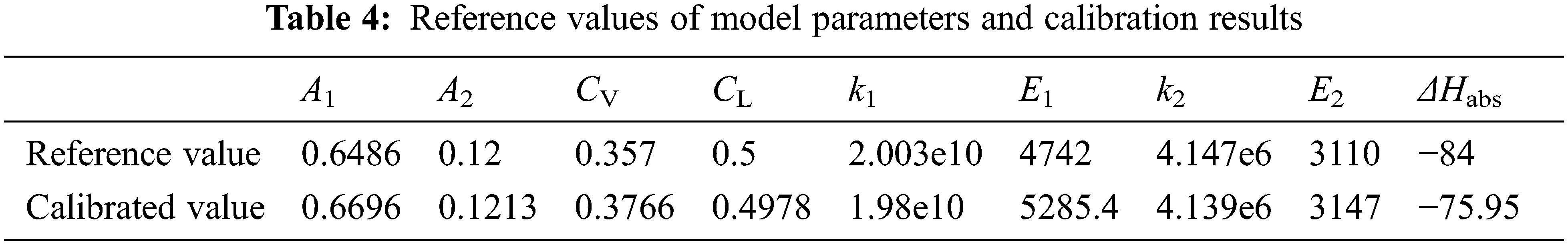
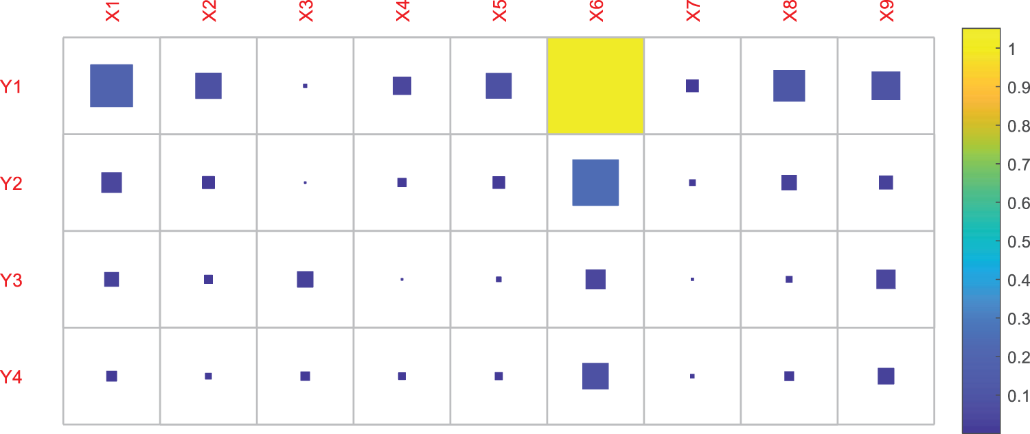
Figure 4: Visualization of the sensitivity matrix Γ (element magnitudes are represented by different sizes and colors)
For calibration purpose, in this paper we propose an SVD-based subspace method. Let the SVD of a full rank matrix Γm×n (m < n) be
where the subscripts denote matrix dimensions, S1 is diagonal, U and V are both unity matrices. The following relationship holds:
where
Using these concepts, the SVD-based model calibration method is given as solving the following least square problem:
where k denotes the testing number. Parameter identification is performed in the low dimensional subspace, it not only simplifies solving the optimization problem, but also eliminates the co-linearity in the original parameter space. In addition, it can avoid the ill-conditioning problem due to the lack of experimental data and parameter over-fitting.
Once the optimal T1 is obtained by solving (24), the optimal values of the original parameters are given as
It is worth mentioning that since the parameters are regressed using the experimental data reported in [17], the results reported in Table 4 may not be generally applicable to other CO2 absorbers which have different settings from the one studied here. For example, if the column size is in different scale, or the packing is not Mellapak 250Y, new experimental data should be collected to identify the suitable parameters.
4 Dynamic Simulations for the Absorber
4.1 Change of the Lean Solution Feed Rate
The feed rate of lean solution at the top of absorber is the main manipulated variable for the control of CO2 capture rate, hence the dynamic response is of paramount importance. Take condition #13 as an example, Fig. 5 illustrates the system response for a +50% increase of the lean solution feed rate. Between 0–1 s, the absorber runs at the steady state of condition #13; at t = 1 s, the lean solution federate increases from 6 to 9 l/min, as shown in Fig. 5a. The response is shown in subfigure (b), where the capture rate η quickly increases from 49.7%, and achieves the peak in about 2.4 s (83%); afterwards, η gradually decreases, at about t = 50 s, η reaches the least value of 20%; Finally, η slowly goes back to 56.9% at t = 200 s. The underlying principles are interpreted as follows:
(1) 1–2.4 s, CO2 are quickly absorbed due to the increase of MEA solution, leading to an increase of η;
(2) 2.4–50 s, as much more CO2 is absorbed, the generated heat is released in to the system, which causes an increase of the temperature. As shown in subfigure (c), at t = 2.4 s, the temperature peak is around at the relative height, 0.9. On one hand, the high temperature is against the absorption of CO2; On the other hand, there is a delay of the temperature increase, the over-generated heat leads to a slowly increasing temperature, and due to the heat transfer and movements of liquid from top to bottom, the high temperature gradually moves toward the bottom of the column. As shown in (c) at t = 50 s, the temperature of the whole column has a significant increase;
(3) 50–200 s, as the high temperature solutions are discharged from the bottom, the column’s temperature gradually decreases, which causes the capture ability to increase, and finally reaches the steady state.
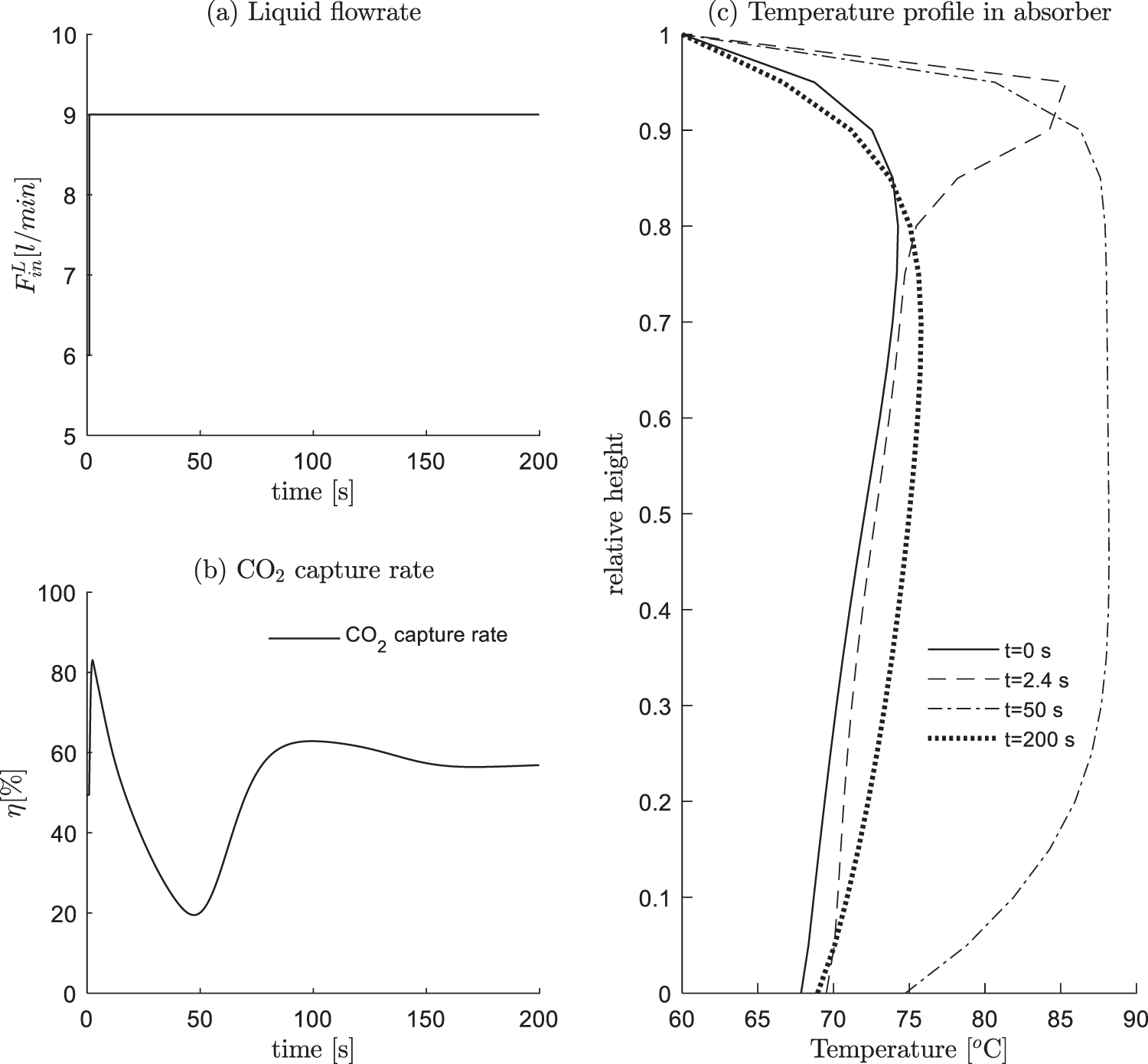
Figure 5: +50% step change of the lean solution feed rate
Regarding the two steady state results (t = 0 and t = 200 s): (i) The CO2 capture rate increases from 49.7% to 56.9%. (2) The temperature peak moves from the relative height 0.85 to about 0.7. This phenomenon is quite general, namely, the higher the capture rate η, the closer the temperature peak to the bottom. In Fig. 6, we additionally compared the positions of temperature peaks under different inlet solution feed rates, where one can observe such a trend.
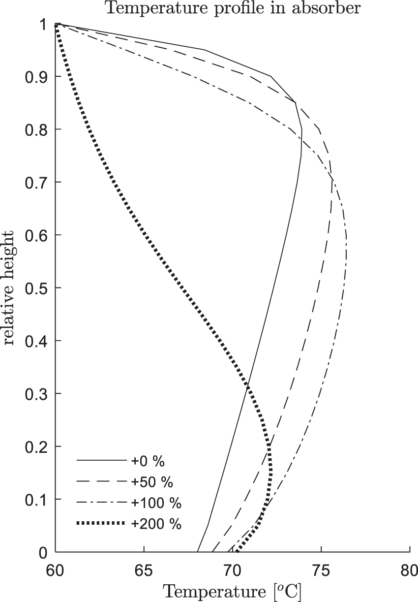
Figure 6: Steady state temperature profiles for different lean solution feed rates (+0%∼+200%)
4.2 Change of the Inlet Gas Condition
The inlet flue gas coming from upstream is the off-gas discharged from electricity generation, whose flow rate and compositions are frequently varying. To simulate these scenarios, we arrange the following experiments: 0–1 s, the absorber runs in steady state at condition #13; at t = 1 s, the feed rate of inlet gas increases from 151 to 201 m3/h; at t = 40 s, the CO2 composition in inlet gas decreases by 50% (0.0532→0.0266), as shown in Fig. 7a. The following results are observed:
(1) Compared with the previous experiment, the transition caused by inlet gas condition change is much shorter. This is due to the high velocity of vapor speed (2–3 m/s). In addition, the entropy contained in vapor phase is relatively low, which imposed a limited impact on the energy balance for the absorber.
(2) As shown in Fig. 7b, t = 1 s, the CO2 capture rate η firstly increases and then decreases, t = 40 s, the CO2 capture rate η firstly decreases and then increases. This is mainly due to the calculation relationship of η, that is, it is computed as the CO2 at the outlet relative to the CO2 at the inlet. When the inlet condition changes, it has a delay effect on the outlet results, which soon causes an inverse change for the index η. This observation is against that in most existing publications, η is widely taken as the controlled variables. However, this scheme seems not appropriate, at least in the case when the inlet gas condition changes. On the contrary, the CO2 outlet composition yCO2,out has a better fitness with the inlet condition changes, namely, the increase of inlet gas feed rate causes an increase of yCO2,out, the increase of inlet CO2 composition yCO2,in causes a decrease of yCO2,out. Actually, from the viewpoint of emission requirement, controlling a specified level of yCO2,out is also more reasonable.
(3) In the testing conditions, the capture rate is between 40% and 50% and the temperature peak is relatively at the absorber’s top, as shown in Fig. 7c.
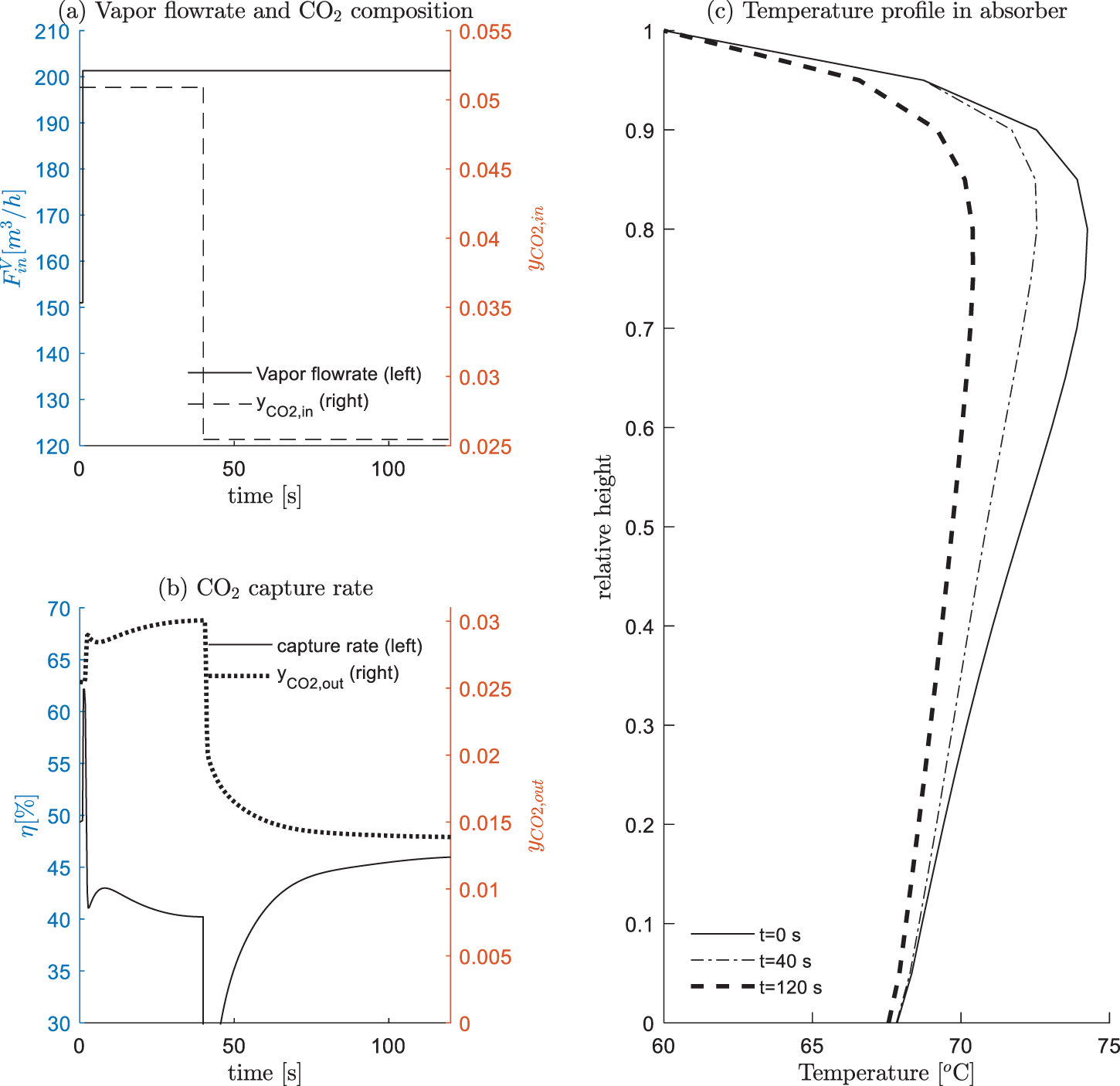
Figure 7: Inlet gas condition changes
In this paper, we established dynamic models for an absorber in the post-combustion MEA-based CO2 capture process. The rate-based reaction relationships can better characterize the material changes in the absorption process. In addition, the GM-based calculation for the enhancement factor is able to more accurately represent the chemical reactions and mass transfer. Experimental data reported in [17] were used to calibrate the model, and an SVD-based parameter identification method was proposed to improve the model accuracy.
Dynamic simulations were conducted to investigate the influences of the lean solution feed rate and the inlet gas conditions. The results showed that when the lean solution feed rate changes, the capture rate η firstly experiences oscillation and then gradually reaches stable. When the inlet gas condition changes, the instantaneous value of η could change oppositely, implying that its calculation should be altered, or different controlled variables should be adopted, such as the CO2 outlet composition yCO2,out. All these results have important indications for the control system design for the absorber, which is the next step of our research works.
Funding Statement: The work was financially supported by Basic Public Welfare research Plan of Zhejiang Province (LGG19F030006), Key Laboratory of Intelligent Manufacturing Quality Big Data Tracing and Analysis of Zhejiang Province, China Jiliang University (Grant No. ZNZZSZ--CJLU2022--04), the Key Research and Development Program of Ningbo (2022Z165).
Conflicts of Interest: The authors declare that they have no conflicts of interest to report regarding the present study.
References
1. E. Kenig, R. Schneider and A. Gorak, “Reactive absorption: Optimal process design via optimal modelling,” Chemical Engineering Science, vol. 56, no. 2, pp. 343–350, 2001. [Google Scholar]
2. C. Biliyok, A. Lawal, M. Wang and F. Seibert, “Dynamic modelling, validation and analysis of post-combustion chemical absorption CO2 capture plant,” International Journal of Greenhouse Gas Control, vol. 9, no. 7, pp. 428–445, 2012. [Google Scholar]
3. A. Lawal, M. Wang, P. Stephenson and H. Yeung, “Dynamic modelling of CO2 absorption for post combustion capture in coal-fired power plants,” Fuel, vol. 88, no. 12, pp. 2455–2462, 2009. [Google Scholar]
4. H. M. Kvamsdal, J. P. Jakobsen and K. A. Hoff, “Dynamic modeling and simulation of a CO2 absorber column for post-combustion CO2 capture,” Chemical Engineering Processing: Process Intensification, vol. 48, no. 1, pp. 135–144, 2009. [Google Scholar]
5. N. E. Flo, H. Knuutila, H. M. Kvamsdal and M. Hillestad, “Dynamic model validation of the post-combustion CO2 absorption process,” International Journal of Greenhouse Gas Control, vol. 41, no. 10, pp. 127–141, 2015. [Google Scholar]
6. N. E. Flo, H. M. Kvamsdal, M. Hillestad and T. Mejdell, “Dominating dynamics of the post-combustion CO2 absorption process,” Computers & Chemical Engineering, vol. 86, no. 3, pp. 171–183, 2016. [Google Scholar]
7. K. R. Putta, F. A. Tobiesen, H. F. Svendsen and H. K. Knuutila, “Applicability of enhancement factor models for CO2 absorption into aqueous MEA solutions,” Applied Energy, vol. 206, no. 11, pp. 765–783, 2017. [Google Scholar]
8. M. Xiao, H. Liu, R. Idem, P. Tontiwachwuthikul and Z. J. Liang, “A study of structure–activity relationships of commercial tertiary amines for post-combustion CO2 capture,” Applied Energy, vol. 184, no., pp. 219–229, 2016. [Google Scholar]
9. K. Li, W. Leigh, P. Feron, H. Yu and M. J. A. E. Tade, “Systematic study of aqueous monoethanolamine (MEA)-based CO2 capture process: Techno-economic assessment of the MEA process and its improvements,” Applied Energy, vol. 165, no. 3, pp. 648–659, 2016. [Google Scholar]
10. J. Gaspar and P. L. Fosbol, “A general enhancement factor model for absorption and desorption systems: A CO2 capture case-study,” Chemical Engineering Science, vol. 138, no. 12, pp. 203–215, 2015. [Google Scholar]
11. S. Posch and M. Haider, “Dynamic modeling of CO2 absorption from coal-fired power plants into an aqueous monoethanolamine solution,” Chemical Engineering Research and Design, vol. 91, no. 6, pp. 977–987, 2013. [Google Scholar]
12. M. S. Walters, Y. J. Lin, D. J. Sachde, T. F. Edgar and G. T. Rochelle, “Control relevant model of amine scrubbing for CO2 capture from power plants,” Industrial & Engineering Chemistry Research, vol. 55, no. 6, pp. 1690–1700, 2016. [Google Scholar]
13. J. C. Morgan, A. S. Chinen, B. Omell, D. Bhattacharyya, C. Tong et al., “Thermodynamic modeling and uncertainty quantification of CO2-loaded aqueous MEA solutions,” Chemical Engineering Science, vol. 168, pp. 309–324, 2017. [Google Scholar]
14. A. S. Chinen, J. C. Morgan, B. Omell, D. Bhattacharyya, C. Tong et al., “Development of a rigorous modeling framework for solvent-based CO2 capture. 1. Hydraulic and mass transfer models and their uncertainty quantification,” Industrial& Engineering Chemistry Research, vol. 57, no. 31, pp. 10448–10463, 2018. [Google Scholar]
15. J. C. Morgan, A. Soares Chinen, B. Omell, D. Bhattacharyya, C. Tong et al., “Development of a rigorous modeling framework for solvent-based CO2 capture. Part 2: Steady-state validation and uncertainty quantification with pilot plant data,” Industrial & Engineering Chemistry Research, vol. 57, no. 31, pp. 10464–10481, 2018. [Google Scholar]
16. P. Akula, J. Eslick, D. Bhattacharyya and D. C. Miller, “Model development, validation, and optimization of an MEA-based post-combustion CO2 capture process under part-load and variable capture operations,” Industrial & Engineering Chemistry Research, vol. 60, no. 14, pp. 5176–5193, 2021. [Google Scholar]
17. F. A. Tobiesen, H. F. Svendsen and O. J. A. Juliussen, “Experimental validation of a rigorous absorber model for CO2 postcombustion capture,” AIChE Journal, vol. 53, no. 4, pp. 846–865, 2007. [Google Scholar]
18. R. Billet and M. Schultes, “Prediction of mass transfer columns with dumped and arranged packings: Updated summary of the calculation method of billet and schultes,” Chemical Engineering Research Design, vol. 77, no. 6, pp. 498–504, 1999. [Google Scholar]
19. R. Weiland, “Physical properties of MEA, DEA, MDEA, and MDEA-based blends loaded with CO2,” GPA research report RR-152, GPA project 911, 1996. [Google Scholar]
20. J. C. Morgan, D. Bhattacharyya, C. Tong and D. C. Miller, “Uncertainty quantification of property models: Methodology and its application to CO2-loaded aqueous MEA solutions,” AIChE Journal, vol. 61, no. 6, pp. 1822–1839, 2015. [Google Scholar]
21. C. L. Yaws, Yaw’s Handbook of Thermodynamic and Physical properties of Chemical Compounds: Physical, Thermodynamic and Transport Properties for 5,000 Organic Chemical Compounds. 1st ed., Beaumont, USA: Knovel Corporation Press, 2003. [Google Scholar]
22. E. O. Agbonghae, K. J. Hughes, D. B. Ingham, L. Ma and M. J. I. Pourkashanian, “A semi-empirical model for estimating the heat capacity of aqueous solutions of alkanolamines for CO2 capture,” Industrial & Engineering Chemistry Research, vol. 53, no. 19, pp. 8291–8301, 2014. [Google Scholar]
23. Y. Jiru, D. A. Eimer and Y. Wenjuan, “Measurements and correlation of physical solubility of carbon dioxide in (monoethanolamine + Water) by a modified technique,” Industrial & Engineering Chemistry Research, vol. 51, no. 19, pp. 6958–6966, 2012. [Google Scholar]
24. C. Wilke, “A viscosity equation for gas mixtures,” The Journal of Chemical Physics, vol. 18, no. 4, pp. 517–519, 1950. [Google Scholar]
25. J. Ying and D. A. Eimer, “Measurements and correlations of diffusivities of nitrous oxide and carbon dioxide in monoethanolamine + water by laminar liquid jet,” Industrial & Engineering Chemistry Research, vol. 51, no. 50, pp. 16517–16524, 2012. [Google Scholar]
26. K. A. Hoff, O. Juliussen, O. Falk-Pedersen and H. F. Svendsen, “Modeling and experimental study of carbon dioxide absorption in aqueous alkanolamine solutions using a membrane contactor,” Industrial & Engineering Chemistry Research, vol. 43, no. 16, pp. 4908–4921, 2004. [Google Scholar]
27. C. C. Li, “Thermal conductivity of liquid mixtures,” AIChE Journal, vol. 22, no. 5, pp. 927–930, 1976. [Google Scholar]
28. X. Luo, A. Hartono, S. Hussain and H. F. Svendsen, “Mass transfer and kinetics of carbon dioxide absorption into loaded aqueous monoethanolamine solutions,” Chemical Engineering Science, vol. 123, no. 2, pp. 57–69, 2015. [Google Scholar]
29. R. E. Tsai, A. F. Seibert, R. B. Eldridge and G. T. Rochelle, “A dimensionless model for predicting the mass-transfer area of structured packing,” AIChE Journal, vol. 57, no. 5, pp. 1173–1184, 2011. [Google Scholar]
30. S. Zhou, Y. Jia and C. Wang, “Global sensitivity analysis for the polymeric microcapsules in self-healing cementitious composites,” Polymers, vol. 12, no. 12, pp. 2990–3003, 2020. [Google Scholar]
Cite This Article
 Copyright © 2023 The Author(s). Published by Tech Science Press.
This work is licensed under a Creative Commons Attribution 4.0 International License , which permits unrestricted use, distribution, and reproduction in any medium, provided the original work is properly cited.
 Downloads
 Citation Tools