
 Submit a Paper
 Propose a Special lssue
 Open Access
ARTICLE

Power Quality Improvement Using ANN Controller For Hybrid Power Distribution Systems
1 B. S. Abdur Rahman Crescent Institute of Science and Technology, A Deemed To Be University, Chennai, Tamil Nadu, 600048, India
2 Jyothishmathi Institute of Technology and Science, Karimnager, Telangana, 505481, India
* Corresponding Author: Abdul Quawi. Email:
Intelligent Automation & Soft Computing 2023, 36(3), 3469-3486. https://doi.org/10.32604/iasc.2023.035001
Received 03 August 2022; Accepted 23 November 2022; Issue published 15 March 2023
 View Full Text
 Download PDF
Abstract
In this work, an Artificial Neural Network (ANN) based technique is suggested for classifying the faults which occur in hybrid power distribution systems. Power, which is generated by the solar and wind energy-based hybrid system, is given to the grid at the Point of Common Coupling (PCC). A boost converter along with perturb and observe (P&O) algorithm is utilized in this system to obtain a constant link voltage. In contrast, the link voltage of the wind energy conversion system (WECS) is retained with the assistance of a Proportional Integral (PI) controller. The grid synchronization is tainted with the assistance of the d-q theory. For the analysis of faults like islanding, line-ground, and line-line fault, the ANN is utilized. The voltage signal is observed at the PCC, and the Discrete Wavelet Transform (DWT) is employed to obtain different features. Based on the collected features, the ANN classifies the faults in an efficient manner. The simulation is done in MATLAB and the results are also validated through the hardware implementation. Detailed fault analysis is carried out and the results are compared with the existing techniques. Finally, the Total harmonic distortion (THD) is lessened by 4.3% by using the proposed methodology.Keywords
Renewable Energy Sources (RES) are regarded as significant sources of energy generation because of having multiple advantages, including environmental protection, global warming reduction, and fossil fuels-free operation. The RES has gained more interest as these sources satisfy the domestic need of the customers with zero pollution by having the features like eco-friendliness and zero emission [1]. Though there are several advantages, it is less reliable for grid-connected cases because the RES integration has specific challenges like intermittent nature and the need for separate control. Due to the fluctuating nature of the RES, there are Power Qualities (PQ) issues [2]. The PQ is a major concern in the power system’s utility and end-user sides. The proper functioning of the power system is ensured only when there are no PQ disturbances, and the worst PQ results in distortions, faults, and load non-linearity. The three major electrical power system components are generation, transmission, and distribution. When a fault occurs in any of these components, the whole system’s performance gets affected, leading to losses on the customer side. Hence, solving the PQ Disturbances (PQD) is necessary, which is still a challenging task [3–5]. In general, the PQ issues fall under two categories: transient and steady state, among which the former includes interruptions, voltage sag/swell, and sudden transient fall, which affects both the customers and the grid with severe impacts [6–8]. To resolve the PQ issues, Custom Power Devices (CPD) are utilized, which mitigate the occurrence of abnormalities in the system but fail to improve the response time [9]. There are numerous techniques used for mitigating the PQD, which are discussed as follows:
The analysis of PQD comprises feature extraction and classification. The Fourier Transform (FT) is utilized for feature extraction, which includes the following types Fast FT (FFT), discrete FT (DFT), and short-time FT (STFT) [10]. In FFT, the signal is assumed as periodic, resulting in inaccurate evaluation because of the spectral leakage during disturbances. As the PQD is assessed in the frequency domain, it fails to provide the time information in relation to the signal appearance. Moreover, the FFT fails to sense the transients of the signal [11,12]. The DFT has a fixed window size, so it is only suitable for non-stationary signals, whereas the STFT, an extended version of DFT, is only applicable to stationary signals [13]. Hence, the Wavelet Transform (WT) is used, which is suitable for variable window sizes with high and low frequencies. In addition, it is also applicable to non-stationary signals. The Discrete WT (DWT) is an extended version of WT, which provides improved frequency and time resolution [14,15].
To classify the PQD an appropriate classifier is essential. So the Classifiers like Fuzzy Logic (FL), Decision Tree (DT), and Support Vector Machine (SVM) are utilized for classifying the PQD. Both the FL and DT are based on rules, and hence there is no need for training. In complex systems, the FL minimizes the modeling complexity, whereas the DT has a simple construction and excellent scalability. However, both FL and DT function based on the data samples correlation, which affects the performance in a broader range. The SVM is a learning process, and it performs well only if the training data set is small [16–21].
The PQD in a PV-wind-based hybrid power distribution system is analyzed in this work. Solar-energy systems are one of the promising RES, which is accessible throughout the year with minimum maintenance cost. As the outcome of the Photovoltaic (PV) module is insufficient, a suitable converter is mandatory for maximizing the PV voltage and so a boost converter is employed for this purpose. The intermittent atmospheric conditions generally affect the PV output and so it is crucial to trace the maximum power from the PV module [22–26]. Wind energy is another RES, which is integrated with PV systems to deliver a continuous power output. The general structure of Wind Energy Conversion Systems (WECS) [27–30] comprises a wind turbine coupled with an electrical generator for obtaining electrical energy. Induction generators (IG) are the commonly used generators for WECS but in this work, a Double Fed IG (DFIG) based wind turbine is utilized [31,32]. While giving the generated energy from the hybrid system to the grid, disruptions are occurred due to load variations. Hence, it is highly essential to perform grid synchronization [33–35].
Generally, a hybrid power distribution system gets affected by the faults like islanding, line-line, line-ground and switching faults. The islanding leads to equipment damage, hazards to workers and even damages to the distribution system, causing PQD. In this work, a PV-wind-based hybrid system is utilized and the PQD that occurs in the system is analyzed. A new proposed approach to grid synchronization is tainted with the assistance of the d-q theory. The voltage signal is observed at the PCC and the Discrete Wavelet Transform (DWT) is employed to obtain different features. Based on the collected features, the ANN classifies the faults in an efficient manner. Finally, the Total harmonic distortion (THD) is come down to IEEE stranded and maintains its power quality.
2 Description of the Proposed System
A hybrid power distribution system is presented in Fig. 1, which comprises of a PV and a WECS. A DC-DC boost converter is utilized for elevating the PV voltage and a DC-AC inverter is utilized for giving the DC voltage to the grid. As the PV output changes in accordance with the climatic variations, the P&O MPPT is employed to extricate the maximum power. Thus, the required gating sequence for controlling the converter is generated. Similarly, a Pulse Width Modulation (PWM) rectifier is utilized in the WECS for AC-DC conversion and a PI controller is utilized for retaining the link voltage
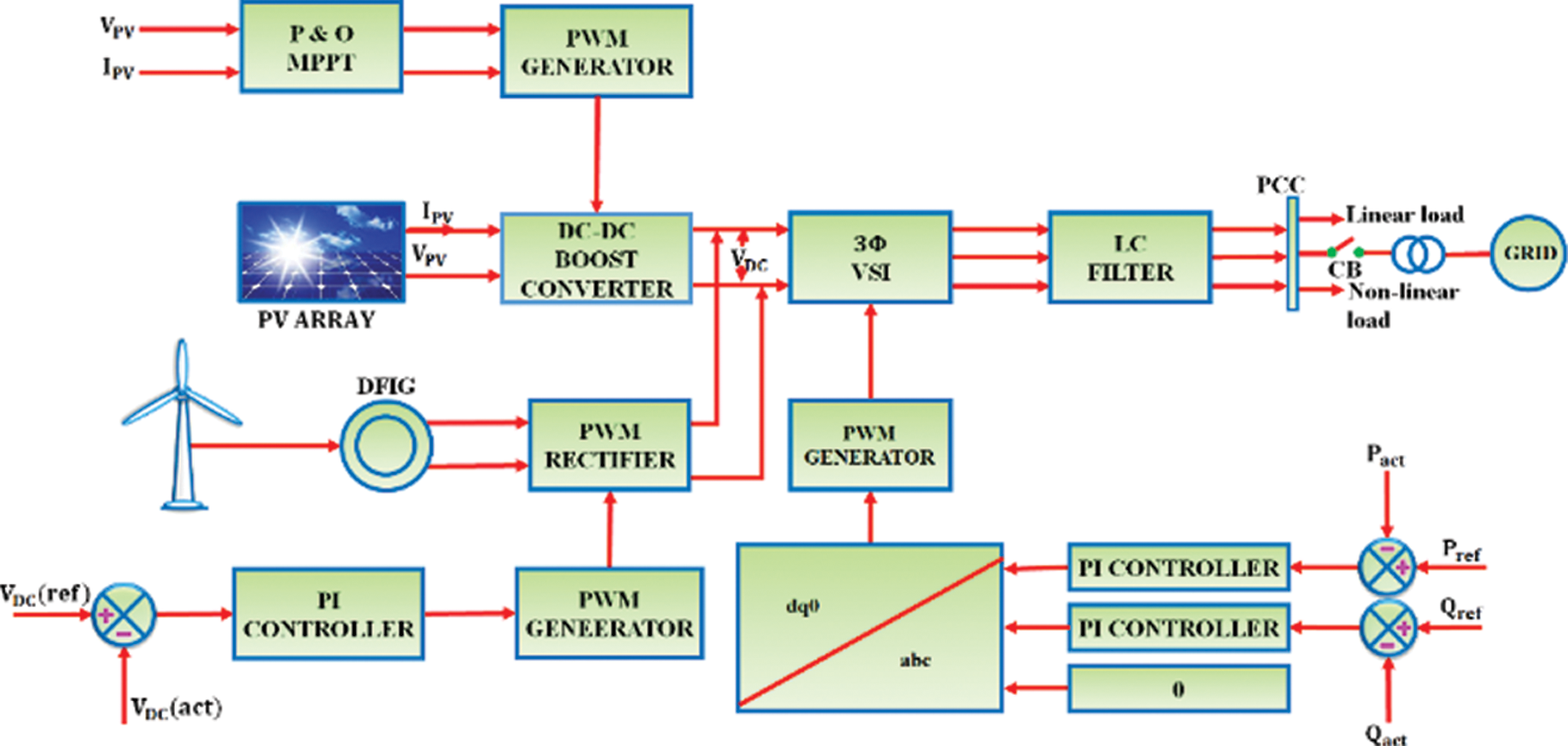
Figure 1: Hybrid power distribution system
When the power generated from this hybrid system is given to the grid, the PQD occur due to the negative-sequence voltage at the PCC. The existing methods for identifying the faults cause imbalances in both the supply and the consumer side. Hence, the Artificial Intelligence (AI) based technique is implemented in this work for classifying the faults. In the process of classifying various kinds of faults, the DWT is used for extracting the features and ANN is utilized as a classifier. As the real time classification of power transients is a challenging task, the AI based technique is adopted for predicting the faults. From the negative sequence component, the discriminative features are extracted at the PCC. The captured signals are thus decomposed to form various frequency bands. The features obtained from the hybrid power distribution systems are used as the training set for ANN. Once the ANN is trained with the discriminative features, it has the capability of identifying the faults with more accuracy.
The term “Hybrid” refers to the combination of two or more different things. In general, the hybrid energy system is utilized to generate electricity to grids. This type of technology makes use of RES like PV and wind energy systems.
When solar cells are linked in series and parallel, a PV module is modelled, which transforms the photon energy into pollution-free power. An electrical circuit is represented by a single solar cell, which comprises a p–n junction diode, a photocurrent generator and two resistances (one in series and other in parallel). It is referred as a single diode solar cell model and the circuit representation of PV module is displayed in Fig. 2.
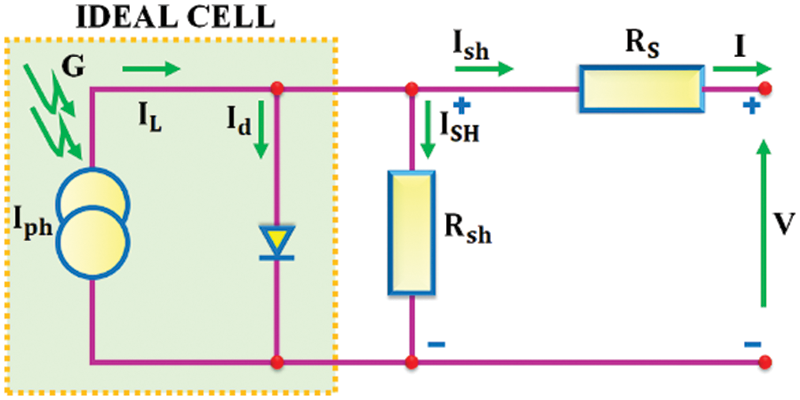
Figure 2: Circuit representation of PV module
The solar PV is modeled as an ideal solar cell with a current source
The Shockley’s diode current equation represented in (2), is the fundamental mathematical equation derived from semiconductor theory that defines the I–V features of the PV solar cell.
The solar cell delivers a good approximation to photon produced current, which is directly proportional to irradiance and intensity of illumination in the ideal condition.
It is utilized to enhance the PV voltage, and the converter performs by the combination of elements like switch, inductance, diode as well as the output capacitance. The boost converter’s circuit representation is displayed in Fig. 3. The switching
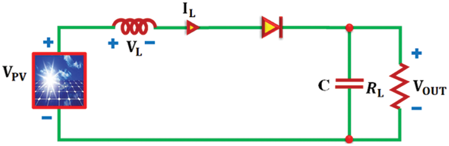
Figure 3: Boost converter’s circuit representation
By utilizing the boost converter, the energy attained from the PV is improved, which is then fed to the grid through inverter.
This approach creates a simple closed loop regulation with only a few controllable variables. This algorithm analogizes the previously provided power with the following disturbance by periodically altering the voltage of PV panel with incremental step. Hence, the fluctuations around the MPP get decreased. Because of its easiness and usage of a few measured variables, this algorithm is widely utilized in various applications. The principle of this approach is explained through the flowchart, which is clearly displayed in Fig. 4.
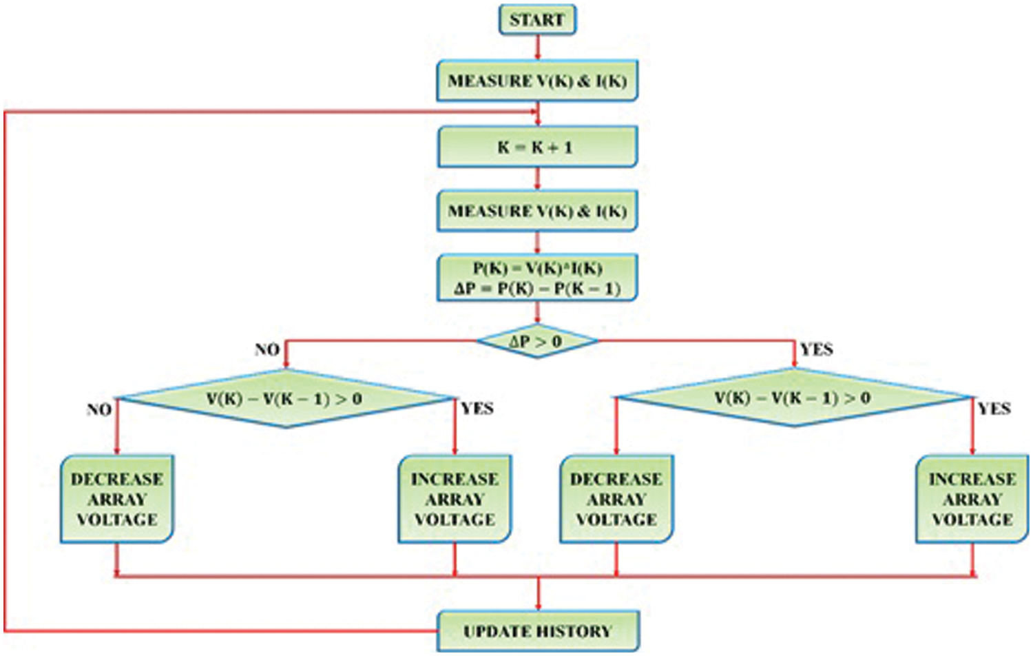
Figure 4: Flowchart of P&O based MPPT
The perturbation inputs from PV panel to MPPT unit are PV voltage
2.2 3Φ VSI and Grid Synchronization
The control block of 3Φ VSI is displayed in Fig. 5. The grid voltages and angles are computed with the help of PLL approach. With the utilization of grid angle, the grid voltages and currents are transferred from
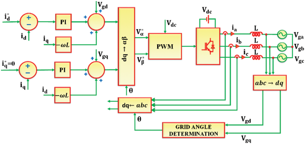
Figure 5: Control block of 3Φ VSI
By analogizing the reference and measured
The grid current’s maximum value determines the reference
The PI controller’s outputs are converted into
The PWM generates switching pulses by using inverter reference voltages in
The grid synchronization is accomplished by synchronizing the inverter output with the grid voltage. The synchronization process’ aim is to extract the grid voltage’s phase angle. With the utilization of extracted grid angle, the feedback parameters are transformed into an appropriate reference frame. Therefore, the process of detecting the grid angle is critical for controlling the grid tied VSI. The variations in the utility network is responded rapidly by utilizing synchronization. In addition, the noise and the higher order harmonics in the output of VSI are significantly mitigated with the assistance of the LC filter. The noise free output of the VSI aids in the process of accomplishing grid synchronization.
By employing MRA, the wavelets provide effective and fast computations to communicate with a signal portion in its distinct frequency groups. The orthogonally symmetrical property aid in signal recreating with minor errors in center signal handling applications. Eq. (7) shows the period representation f (t) and (8) shows the Fourier space representation f (w). The period representation f (t) should be provides data with extreme time determination and provide no frequency data whereas the Fourier space representation f(w) provides frequency data but provides no time confinement.
Due to the lack of time data in Fourier Transform, a Windowed Fourier Transform is utilized instead of Fourier Transform. In this case, the signal is divided into little segments and each of which is considered as stationary. To make the signal as stationary, it is essential to limit the window at the same period, which causes lower frequency resolution. The wavelets limit the flag in both spaces of frequency and time. This wavelet structure is formed from a mother wavelet, which expands or extends the size of window. This implies that an enlarged wavelet provides more time data whereas an extended version provides frequency data. The wavelet utilizes different window size, which adjusts both the segments of low and high frequencies. The wavelets are formed by development and expansions from a mother wavelet Ψ. It is expressed as,
where,
It is a non-linear data operating self-adaptive system, which is utilized to categorize the data. Because of the advantage of easiness, the Multi-layered Fed Forward Neural Network (MLFFNN) is utilized and its structure is displayed in Fig. 6.
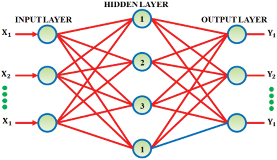
Figure 6: Multi layered feed forward neural network structure
It has three layers such as input, output and hidden layers. All of the layers are fed forward and completely integrated. The outputs are controlled by weights, which are determined during the process of cognition. The error Back Propagation (BP) approach is commonly utilized to train the MLFFNN in a supervised manner. The information regarding errors is also filtered, which improves the performance by adjusting the connections between layers. The features obtained from the hybrid power distribution systems are used as the training set for MLFFNN, which is regarded as one of the significant novelties of the system because the implementation of this MLFFNN in the hybrid system with RE sources is an innovative development in the recent days. There are two passes in the error Back Propagation approach such as forward and backward passes. An input is applied to the network’s sensory nodes in forward pass and its influence is propagated through the network layer. A set of output is generated due to the network’s actual response. The result is an error signal, which is subtracted from a desired response and the output is transmitted backwards through the network against the synaptic connection’s direction. The weights are modified to bring the network’s actual response closer to the desired response. The requirements of MLFFNN’s designing and training are as follows,
• The number of hidden layers has to be chosen.
• The number of neurons in every hidden layer has to be chosen.
• The best solution has to be accomplished while avoiding local minima.
The above mentioned requirements are not essential for the discrete DWT and so it optimizes the ANN network architecture in an efficient manner. The detection of various PQ issues in the distribution system is essential for the PQ assessment. To accomplish this, an Energy Entropy based DWT and ANN is proposed, which assist in the automatic detection and discrimination of various PQD.
A hybrid PV-WECS is analyzed in this work. The PV system includes a boost converter, which boosts the PV voltage. Though the PV voltage gets boosted, it is impossible to attain the maximum power from PV because of its intermittency. Hence, the P&O MPPT is utilized for tracing the full power from the PV and accordingly, the pulses are generated for controlling the boost converter, which aids in retaining a constant. The output of both PV and WECS are coupled at the common point, which is then nourished to the grid through a VSI. Finally, grid synchronization is attained by using the d-q theory. The complete setup is verified through the simulation in MATLAB.
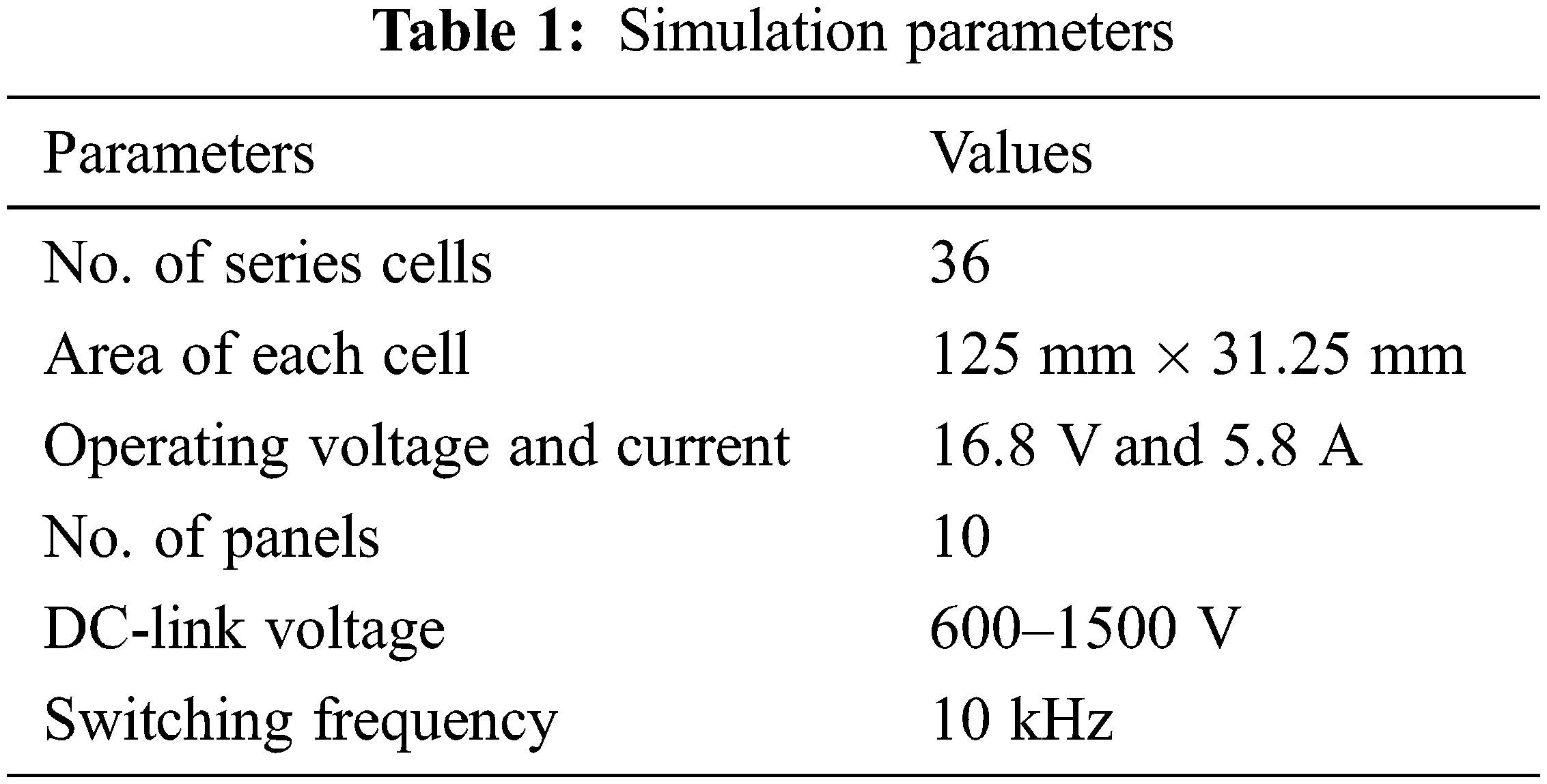
The hybrid energy system is simulated in MATLAB and the following waveforms are observed. The simulation parameters are displayed in Table 1.
The simulation is performed for a time period of 0.2 s and the outcomes are clearly validated through the aforementioned waveforms in Fig. 7, which depicts that the PV voltage is observed as 180 V whereas the PV panel’s current is observed as 20 A. These PV parameters are fed as the input for the boost converter.
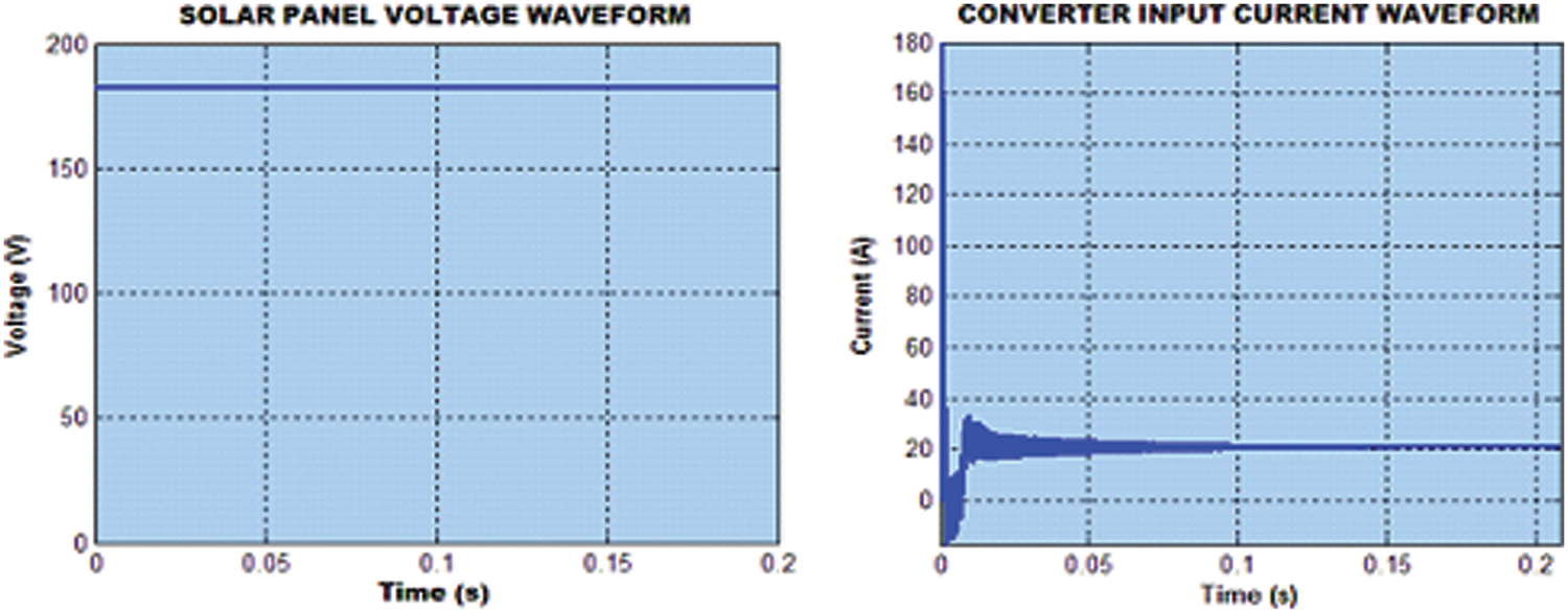
Figure 7: PV parameters
As the PV output is affected by the varying whether conditions, it is essential to extract the maximum power. Hence, the P&O algorithm is utilized for the tracking of the maximum power, in which the control is made based on the observed values of PV voltage and current. The boost converter boosts the PV voltage as 600 V with the settling time of 0.05 s (Fig. 8) and the converter’s current is also observed as 6 A.
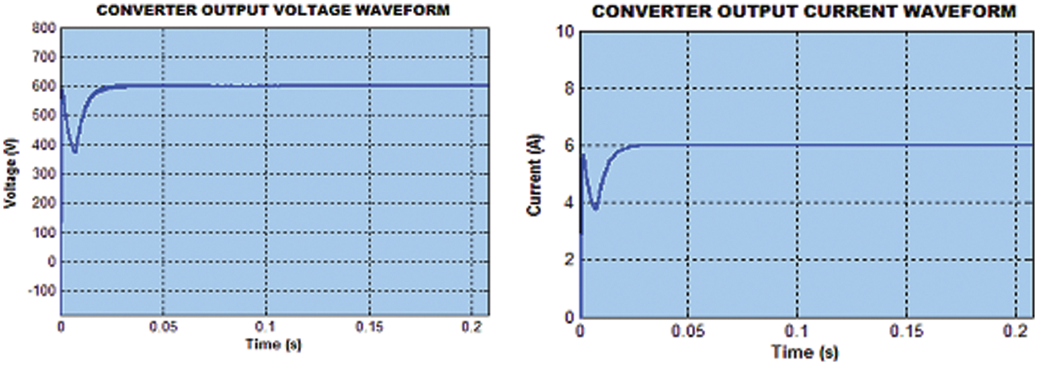
Figure 8: Boost converter parameters
The PV system is hybridized with the WECS, in which the wind speed is observed as 15 m/s. The energy is generated from the rotational speed and the DFIG based wind turbine is utilized in this work to generate the electrical energy. The output voltage of the DFIG is in the range of +600V to −600V (Fig. 9). It is then fed to the PWM rectifier, which performs the AC-DC conversion. As both the PV and WECS are coupled at the common dc-link, it is observed that both the PV and WECS output at the dc-link are the same with a voltage of 600V.
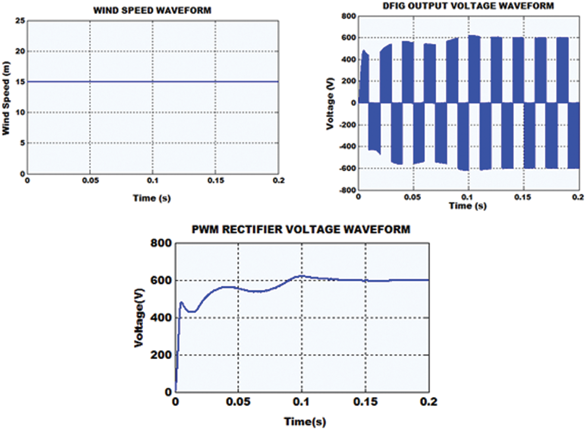
Figure 9: WECS parameters
When the output of PV and WECS are fed to the grid through the VSI, there is a possibility of imbalance between the grid and the VSI parameters. Hence, grid synchronization is done with the assistance of d-q theory. The resultant grid voltage and grid current are observed as highlighted in Fig. 10. The grid voltage is in the range of +330 to −330 V whereas the grid current is observed in the range of +10A to −10A.
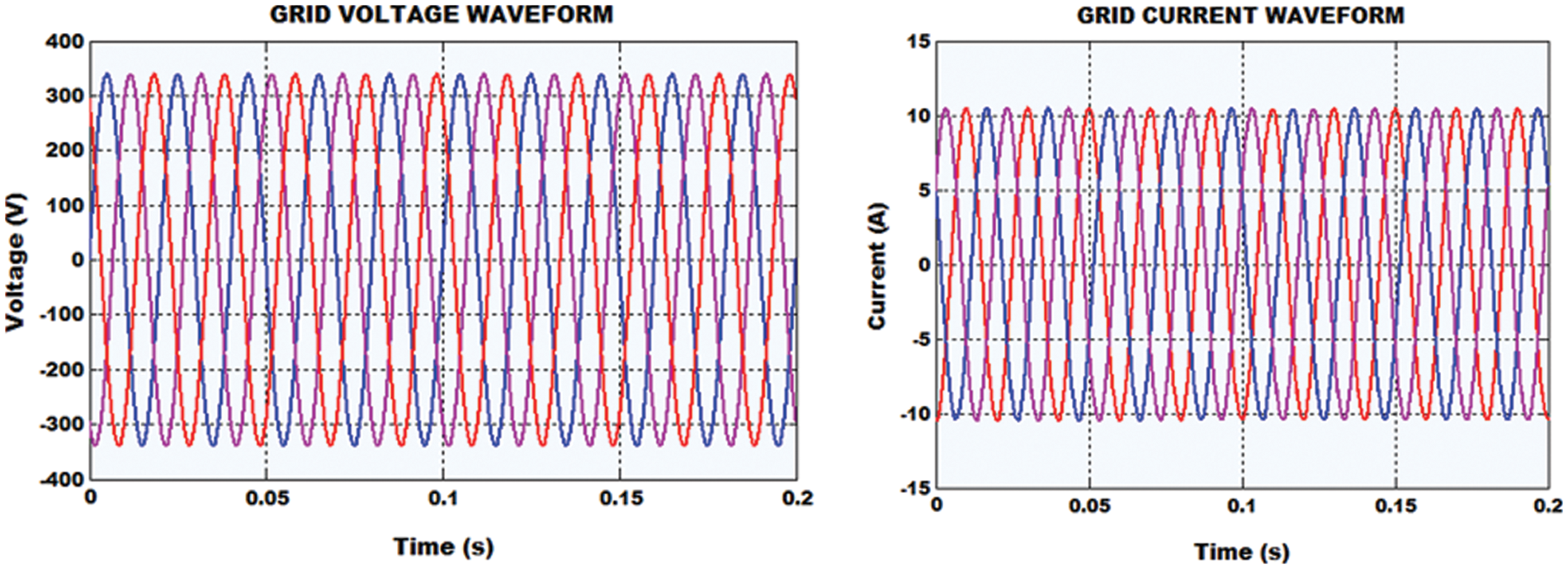
Figure 10: Grid parameters
The real and the reactive power are portrayed in Fig. 11, which reveals that the real power is noted as 5200 W. The THD is also revealed in Fig. 12, which is observed as 4.3%.
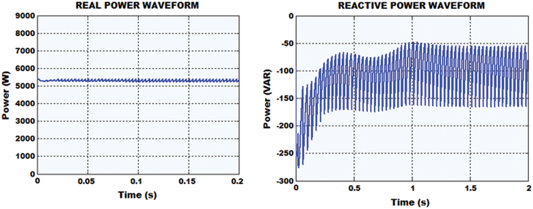
Figure 11: Grid illustration of real and reactive power
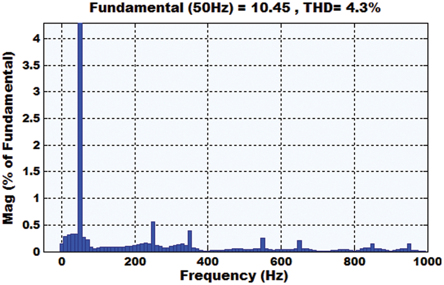
Figure 12: Grid current THD
The proposed work is also validated through hardware implementation in Fig. 13. A prototype model is developed with FPGA Spartan 6E controller for the PV-wind based hybrid power distribution system, in which a boost converter is utilized in the PV system and a PWM rectifier is utilized in the WECS.
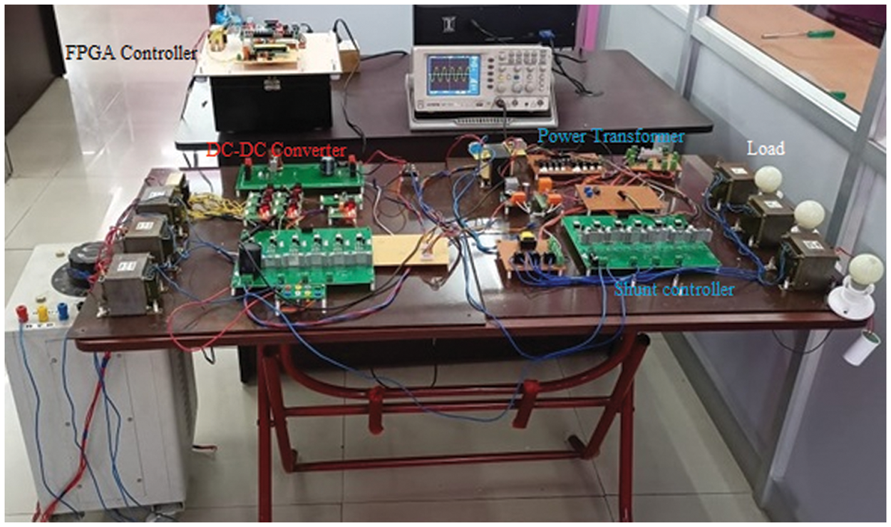
Figure 13: Hardware setup
Similar to the simulation observations, the outcomes are verified by using the hardware setup. The PV current and voltage are portrayed in Fig. 14, which reveals that the PV voltage is almost constant. The PV current shows oscillations at the initial stage and then it is retained constant. This PV voltage is injected to the boost converter and the P&O MPPT is utilized for obtaining the maximum power from the PV. The voltage and current of the converter are portrayed in Fig. 15. The WECS is hybridized with the PV system. The output voltage of the DFIG and the PWM rectifier are highlighted in Fig. 16. The d-q theory based grid synchronization is accomplished and the grid voltage and grid current are in-phase with each other. Fig. 17 validates that the THD of 4.5% is attained.
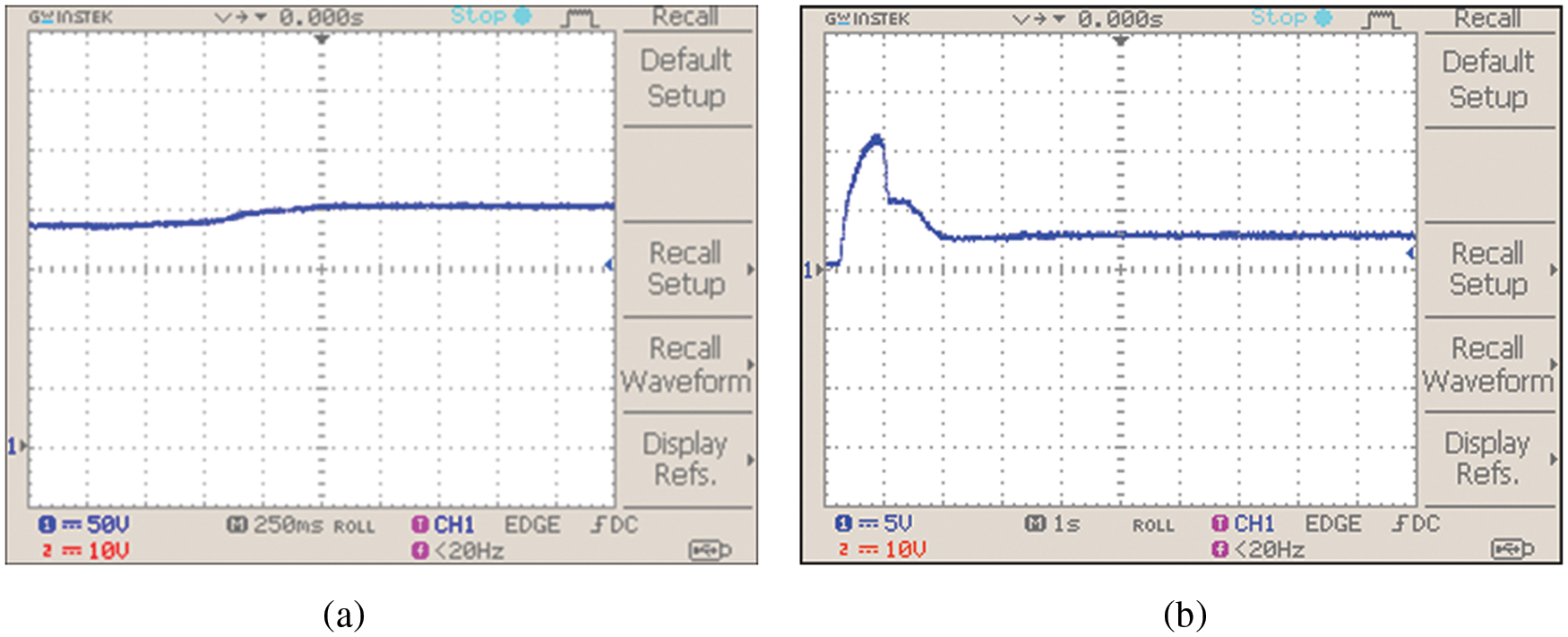
Figure 14: Illustrations of (a) PV voltage (b) PV current
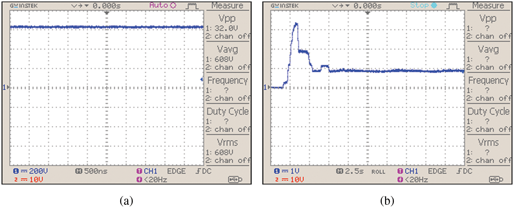
Figure 15: Boost converter’s (a) voltage illustration (b) current illustration
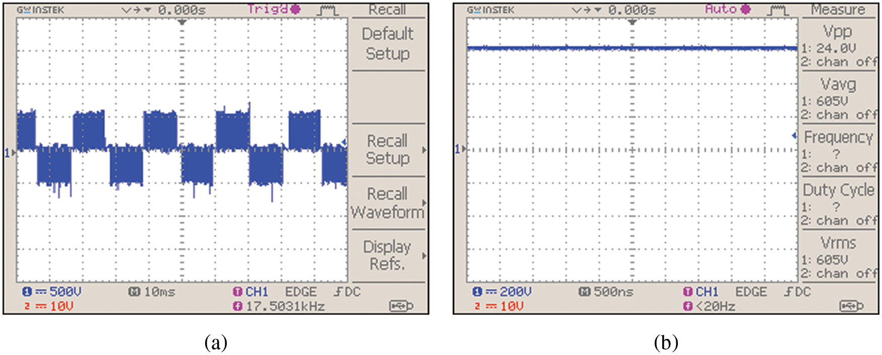
Figure 16: (a) DFIG output (b) rectifier’s output voltage
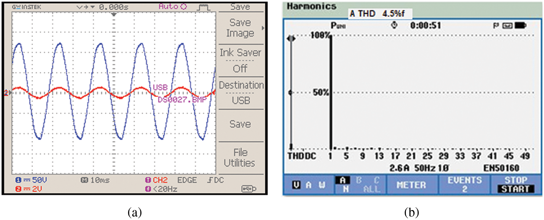
Figure 17: (a) Grid voltage and current (b) grid current THD
A detailed fault analysis is carried out for different conditions like islanding, line-ground fault, line-line fault. For analysing the faults, the ANN is utilized in which DWT is used for extracting the features.
Islanding is the condition, in which the distributed generation continues to supply power even in the absence of the grid power. This is a hazardous condition, which harms the utility workers and stops the automatic reconnection of devices.
By using the ANN, the islanding is detected and the parameters like grid voltage, grid current, real and reactive power are observed (Fig. 18). From the grid voltage waveform, it is revealed that the voltage increases at the time of 0.5 to 0.6 s whereas the grid current shows less oscillations.
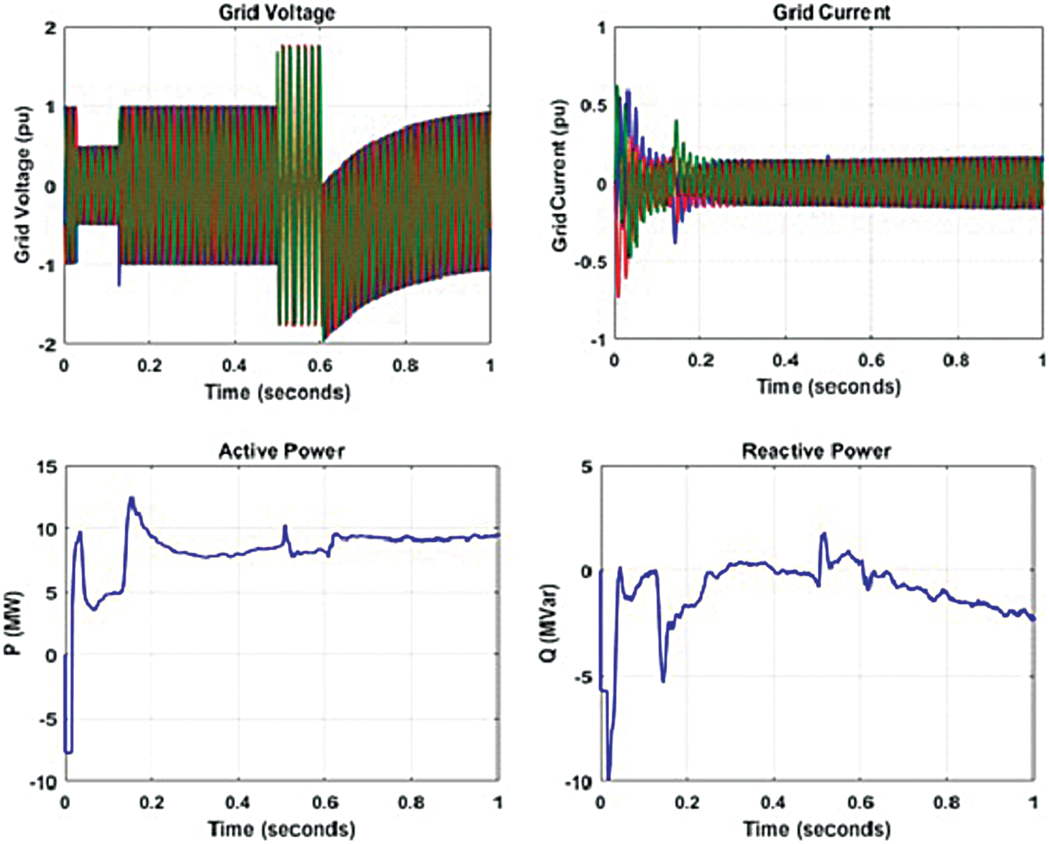
Figure 18: Parameters observed during islanding
Line-ground fault arises in a power distribution system when the conductor comes in contact with the neutral conductor or when it drops to the ground.
By using the ANN, the line-ground fault is detected and various parameters are observed as highlighted in Fig. 19. From 0.5 to 0.6 s, there grid voltage shows a slight fall and the corresponding change is produced in the grid current also. At this instant, the active power falls to 6 MW and the corresponding changes in reactive power is also given in Fig. 20.
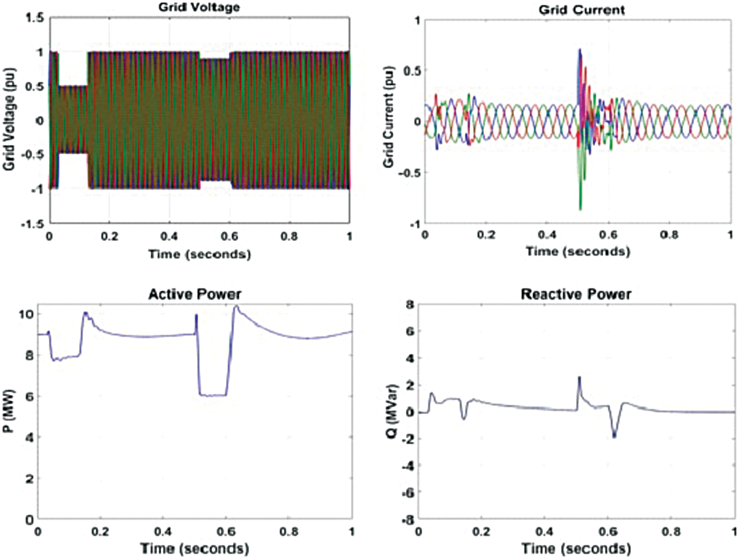
Figure 19: Parameters observed during line-ground fault
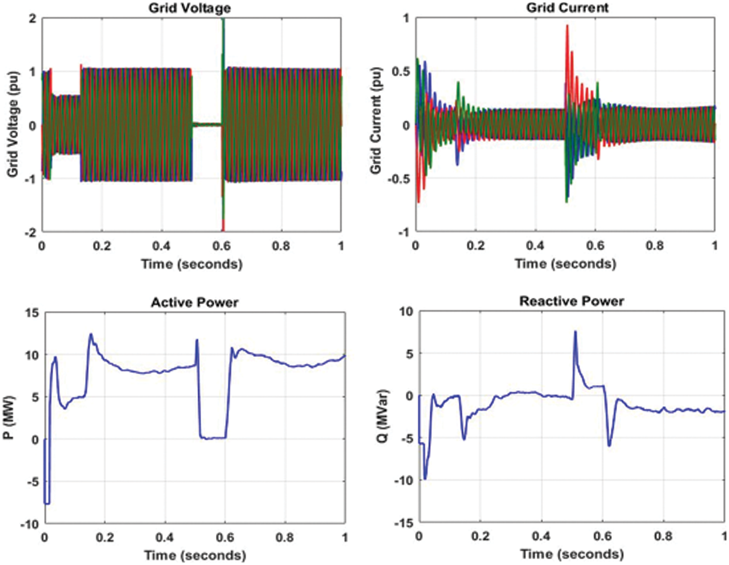
Figure 20: Parameters observed during line-line fault
This type of fault occurs in a power distribution system, in which two phase conductors are short-circuited.
In this work, the DWT is utilized for feature extraction and ANN is used to classify the faults. Hence, the line-line fault is detected and the corresponding parameters are highlighted in Fig. 20. At the time of 0.5 to 0.6 s, the grid voltage is observed as almost zero whereas the grid current shows spikes. At the same instant, the active power decreases to zero and the reactive power rises at 0.5 s.
The performance of the ANN classifier is analogized with DT and SVM as given in Fig. 21 and it reveals that the ANN has a better accuracy of 93%. The sensitivity and specificity of the ANN classifier are also better than the DT and SVM.
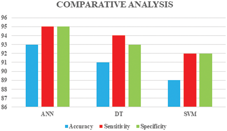
Figure 21: Comparison of ANN with DT and SVM
The PQD in a hybrid power distribution system is analyzed in this work, in which a PV-wind-based hybrid system is considered. The low oscillating PV voltage is boosted with the assistance of the boost converter and the maximum power is tracked with the aid of the P&O algorithm. In WECS, a PWM rectifier is utilized, which is regulated by a PI controller. The controlled dc-link voltage is given to the grid through an inverter and grid synchronization is done with the assistance of d-q theory. The simulation is done in MATLAB and the parameters of the PV and WECS are observed. In addition, the fault analysis is done and the performance is observed under normal islanding as well as a line-ground fault. The features are extracted from the voltage signal by using DWT and ANN is utilized for classifying the faults, which leads to the detection of Line to line faults. Finally, the obtained results are compared with the existing methodologies like SVM and DT, from which it is concluded that the ANN classifies more efficiently than the other techniques. In addition, it has an accuracy of 93%, which is comparatively better than the SVM and DT. Moreover, the specificity and sensitivity of the ANN classifier are also found to be more efficient than the other techniques. From the simulation results, the grid current THD is noted as 4.3% and this leads to reduced power quality issues in the distribution system.
Funding Statement: The authors received no specific funding for this study.
Conflicts of Interest: The authors declare that they have no conflicts of interest to report regarding the present study.
References
1. A. Qazi, F. Hussain, N. A. Rahim, G. Hardaker, D. Alghazzawi et al., “Towards sustainable energy: A systematic review of renewable energy sources, technologies, and public opinions,” IEEE Access, vol. 7, pp. 63837–63851, 2019. [Google Scholar]
2. X. Liang, “Emerging power quality challenges due to integration of renewable energy sources,” IEEE Transactions on Industry Applications, vol. 53, no. 2, pp. 855–866, 2017. [Google Scholar]
3. F. Nejabatkhah, Y. W. Li and H. Tian, “Power quality control of smart hybrid AC/DC microgrids: An overview,” IEEE Access, vol. 7, pp. 52295–52318, 2019. [Google Scholar]
4. F. Harirchi and M. G. Simões, “Enhanced instantaneous power theory decomposition for power quality smart converter applications,” IEEE Transactions on Power Electronics, vol. 33, no. 11, pp. 9344–9359, 2018. [Google Scholar]
5. M. S. Manikandan, S. R. Samantaray and I. Kamwa, “Detection and classification of power quality disturbances using sparse signal decomposition on hybrid dictionaries,” IEEE Transactions on Instrumentation and Measurement, vol. 64, no. 1, pp. 27–38, 2015. [Google Scholar]
6. S. Hedia, B. Zitouna, J. Ben Hadj Slama and L. Pichon, “Electromagnetic time reversal in the near field: Characterization of transient disturbances in power electronics,” IEEE Transactions on Electromagnetic Compatibility, vol. 62, no. 5, pp. 1869–1878, 2020. [Google Scholar]
7. L. Kong, D. Chen, S. -F. Hsiao, C. -F. Nien, C. -J. Chen et al., “A novel adaptive-ramp ripple-based constant on-time buck converter for stability and transient optimization in wide operation range,” IEEE Journal of Emerging and Selected Topics in Power Electronics, vol. 6, no. 3, pp. 1314–1324, 2018. [Google Scholar]
8. Y. Wang, Q. Li and F. Zhou, “Transient power quality disturbance denoising and detection based on improved iterative adaptive kernel regression,” Springer Journal of Modern Power Systems and Clean Energy, vol. 7, no. 3, pp. 644–657, 2019. [Google Scholar]
9. R. K. Agarwal, I. Hussain and B. Singh, “Application of LMS-based NN structure for power quality enhancement in a distribution network under abnormal conditions,” IEEE Transactions on Neural Networks and Learning Systems, vol. 29, no. 5, pp. 1598–1607, 2018. [Google Scholar] [PubMed]
10. N. M. Khoa and L. V. Dai, “Detection and classification of power quality disturbances in power system using modified-combination between the stockwell transform and decision tree methods,” MDPI Energies, vol. 13, no. 3, pp. 256–268, 2020. [Google Scholar]
11. M. M. Islam, M. R. Hossain, R. A. Dougal and C. W. Brice, “Analysis of real-world power quality disturbances employing time-frequency distribution,” Clemson University Power Systems Conference (PSC), vol. 1, pp. 1–5, 2016. [Google Scholar]
12. M. Mishra, “Power quality disturbance detection and classification using signal processing and soft computing techniques: A comprehensive review,” Wiley & Sons International Transactions on Electrical Energy Systems, vol. 28, no. 8, pp. 1159, 2019. [Google Scholar]
13. Y. Shen, M. Abubakar, H. Liu and F. Hussain, “Power quality disturbance monitoring and classification based on improved pca and convolution neural network for wind-grid distribution systems,” MDPI Energies, vol. 12, no. 8, pp. 1280, 2019. [Google Scholar]
14. S. H. Rupal, S. R. Mohanty, N. Kishor and A. T. K., “Real-time implementation of signal processing techniques for disturbances detection,” IEEE Transactions on Industrial Electronics, vol. 66, no. 5, pp. 3550–3560, 2019. [Google Scholar]
15. S. Upadhyaya and S. Mohanty, “Localization and classification of power quality disturbances using maximal overlap discrete wavelet transform and data mining based classifiers,” Elsevier IFAC-Papers Online, vol. 49, no. 1, pp. 437–442, 2016. [Google Scholar]
16. M. Markovska, D. Taskovski, Z. Kokolanski, V. Dimchev and B. Velkovski, “Real-time implementation of optimized power quality events classifier,” IEEE Transactions on Industry Applications, vol. 56, no. 4, pp. 3431–3442, 2020. [Google Scholar]
17. M. Venkateswara Reddy and R. Sodhi, “A modified s-transform and random forests-based power quality assessment framework,” IEEE Transactions on Instrumentation and Measurement, vol. 67, no. 1, pp. 78–89, 2018. [Google Scholar]
18. O. A. Alimi, K. Ouahada and A. M. Abu-Mahfouz, “A review of machine learning approaches to power system security and stability,” IEEE Access, vol. 8, pp. 113512–113531, 2020. [Google Scholar]
19. M. Shafiullah, M. A. Abido and Z. Al-Hamouz1, “Wavelet-based extreme learning machine for distribution grid fault location,” IET Generation, Transmission & Distribution, vol. 11, no. 17, pp. 4256–4263, 2017. [Google Scholar]
20. Y. Shen, H. Wang, Z. Shen, Y. Yang and F. Blaabjerg, “A 1-MHz series resonant DC-DC converter with a dual-mode rectifier for PV microinverters,” IEEE Transactions on Power Electronics, vol. 34, no. 7, pp. 6544–6564, 2019. [Google Scholar]
21. K. V. G. Raghavendra, K. Zeb, A. Muthusamy, T. N. V. Krishna, S. V. S. V. Prabhudeva Kumar et al., “A comprehensive review of DC-DC converter topologies and modulation strategies with recent advances in solar photovoltaic systems,” MDPI Electronics, vol. 9, no. 1, pp. 31, 2019. [Google Scholar]
22. A. K. Podder, N. K. Roy and H. R. Pota, “MPPT methods for solar PV systems: A critical review based on tracking nature,” IET Renewable Power Generation, vol. 13, no. 10, pp. 1615–1632, 2019. [Google Scholar]
23. K. B. Tawfiq, A. S. Mansour, H. S. Ramadan, M. Becherif and E. E. El-kholy, “Wind energy conversion system topologies and converters: Comparative review,” Elsevier Energy Procedia, vol. 162, no. 1–2, pp. 38–47, 2019. [Google Scholar]
24. E. Koutroulis, “Energy management in wind energy systems,” Elsevier Comprehensive Energy Systems, vol. 5, pp. 707–741, 2018. [Google Scholar]
25. P. Gawhade and A. Ojha, “Recent advances in synchronization techniques for grid-tied PV system: A review,” Elsevier Energy Reports, vol. 7, no. 2, pp. 6581–6599, 2021. [Google Scholar]
26. M. Manikandan, P. Balakishan and I. A. Chidambaram, “Improvement of power quality in grid-connected hybrid system with power monitoring and control based on internet of things approach,” Electrical Engineering & Electromechanics, vol. 8, no. 4, pp. 44–50, 2022. [Google Scholar]
27. M. Manikandan, S. G. Reddy and S. Ganapathy, “Three phase four switch inverter based DVR for power quality improvement with optimized CSA approach,” IEEE Access, vol. 10, pp. 72263–72278, 2022. [Google Scholar]
28. M. Manikandan, T. Praveen Kumar and S. Ganapathy, “Improvement of voltage stability for grid connected solar photovoltaic systems using static synchronous compensator with recurrent neural network,” Electrical Engineering & Electromechanics, vol. 2, pp. 69–77, 2022. [Google Scholar]
29. M. Manikandan C. Sathish and I. A. Chidambram, “Reactive power compensation in a hybrid renewable energy system through fuzzy based boost converter,” Problems of the Regional Energetics, vol. 1, no. 53, pp. 53–66, 2022. [Google Scholar]
30. M. Manikandan, S. Gopal Reddy and S. Ganapathy, “Power quality improvement in distribution system based on dynamic voltage restorer using PI tuned fuzzy logic controller,” Electrical Engineering & Electromechanics, vol. 8, no. 1, pp. 44–50, 2022. [Google Scholar]
31. V. Babu, K. S. Ahmed, Y. M. Shuaib and M. Manikandan, “Power quality enhancement using dynamic voltage restorer (DVR) based predictive space vector transformation (PSVT) with proportional resonant (PR)-controller,” IEEE Access, vol. 9, pp. 155380– 155392, 2021. [Google Scholar]
32. V. Babu, K. S. Ahmed, Y. M. Shuaib and M. Mani, “A novel intrinsic SPACE vector transformation based solar fed dynamic voltage restorer for power quality improvement in distribution system,” Journal of Ambient Intelligence and Humanized Computing, vol. 10, no. 9, pp. 7102–7114, 2021. [Google Scholar]
33. V. Babu, K. S. Ahmed, Y. M. Shuaib and M. Manikandan, “Voltage sag/swell compensation using solar photovoltaic inverter based dynamic voltage restorer (SPVI-DVR),” Journal of Green Engineering (JGE), vol. 10, no. 9, pp. 7102–7114, 2020. [Google Scholar]
34. V. Babu, S. S. Basha, Y. M. Shuaib and M. Manikandan, “A novel integration of solar fed dynamic voltage restorer for compensating sag and swell voltage in distribution system using enhanced space vector pulse width modulation (ESVPWM),” Universal Journal of Electrical and Electronic Engineering, vol. 6, no. 5, pp. 329–350, 2019. [Google Scholar]
35. M. Manikandan and A. M. Basha, “ODFF: Optimized dual fuzzy flow controller based voltage sag compensation for SMES-based DVR in power quality applications, Circuits and Systems,” Scientific Research Publication, vol. 7, no. 10, pp. 2959–2974, 2016. [Google Scholar]
Cite This Article
 Copyright © 2023 The Author(s). Published by Tech Science Press.
This work is licensed under a Creative Commons Attribution 4.0 International License , which permits unrestricted use, distribution, and reproduction in any medium, provided the original work is properly cited.
 Downloads
 Citation Tools