
 Submit a Paper
 Propose a Special lssue
 Open Access
ARTICLE

Parallel Iterative FEM Solver with Initial Guess for Frequency Domain Electromagnetic Analysis
1 Department of Electrical Engineering, Incheon National University, Incheon, 22012, Korea
2 Department of Computer Engineering, Hongik University, Seoul, 04066, Korea
3 Department of Electronic Engineering, Gachon University, Seongnam, 13120, Korea
4 Department of IT Convergence Software, Seoul Theological University, Bucheon, 14754, Korea
* Corresponding Author: Moonseong Kim. Email:
Intelligent Automation & Soft Computing 2023, 36(2), 1585-1602. https://doi.org/10.32604/iasc.2023.033112
Received 08 June 2022; Accepted 19 August 2022; Issue published 05 January 2023
 View Full Text
 Download PDF
Abstract
The finite element method is a key player in computational electromagnetics for designing RF (Radio Frequency) components such as waveguides. The frequency-domain analysis is fundamental to identify the characteristics of the components. For the conventional frequency-domain electromagnetic analysis using FEM (Finite Element Method), the system matrix is complex-numbered as well as indefinite. The iterative solvers can be faster than the direct solver when the solver convergence is guaranteed and done in a few steps. However, such complex-numbered and indefinite systems are hard to exploit the merit of the iterative solver. It is also hard to benefit from matrix factorization techniques due to varying system matrix parts according to frequency. Overall, it is hard to adopt conventional iterative solvers even though the system matrix is sparse. A new parallel iterative FEM solver for frequency domain analysis is implemented for inhomogeneous waveguide structures in this paper. In this implementation, the previous solution of the iterative solver of Matlab (Matrix Laboratory) employing the preconditioner is used for the initial guess for the next step’s solution process. The overlapped parallel stage using Matlab’s Parallel Computing Toolbox is also proposed to alleviate the cold starting, which ruins the convergence of early steps in each parallel stage. Numerical experiments based on waveguide structures have demonstrated the accuracy and efficiency of the proposed scheme.Keywords
The analysis of electromagnetic structures requires solving the Maxwell equation according to structural specialties; however, obtaining an analytical solution is usually limited to particular cases with strong symmetry [1]. Therefore, numerical electromagnetism for designing and simulating RF (Radio Frequency) components is indispensable. Among these RF components, a particular device for efficiently transmitting electromagnetic waves through a specific path is collectively referred to as a guided structure, and the waveguide structure may be classified mainly into two types; transmission lines and waveguides. One of the waveguides, a hollow rectangular tube surrounded by a conductor, that is, a rectangular waveguide structure, may reduce attenuation in a high-frequency band, thereby enabling efficient energy transmission in the band [2]. However, it is not easy to obtain an analytical solution when an inhomogeneous block is located in these rectangular waveguides, and it must be helped by computational techniques.
Representative electromagnetic numerical techniques include a finite difference time domain (FDTD), a method of moment (MoM), and a finite element method (FEM). FDTD is a method of interpreting Maxwell’s equations using differential equations in the time domain, which can easily handle the anisotropy and inhomogeneity of the medium and is known to be simple to generate meshes but challenging to model curved surfaces [3]. MoM is a method of interpreting the Maxwell equation using an integral equation using a green function. Since the computational domain is limited to the surface, it does not require the interpretation of a large domain [3]. However, native MoM is known to be challenging to interpret inhomogeneous media, and it also has the disadvantage of complicated calculations because it deals with a full matrix [1,3].
Contrary to the techniques described above, FEM is a type of electromagnetic analysis method based on differential equations and is based on dividing the region of interpretation into finite elements. Although this technique is known to be more mathematically complex than other numerical methods, it is possible to model complex structures and curves using meshes such as triangles and tetrahedrons. Furthermore, the matrix to be solved becomes a sparse matrix; hence it can effectively adopt iterative solvers [4]. In addition, it has the advantage of being suitable for parallel operations by applying a domain decomposition algorithm [5].
However, in the analysis of the frequency domain of FEM, the system matrix subject to the solution becomes a complex matrix with an indefinite property [6]. In addition, since these system matrices vary with frequency, it is not easy to take advantage of the matrix factorization techniques, and due to the above characteristics, they show very slow convergence for iterative solvers. Since the solution time is dominant in the overall analysis time, reduction in the solution time is the key to improve the simulation performance [7,8].
This paper presents the analysis results of the S11 parameter of the inhomogeneous rectangular waveguide using the edge element of FEM. The simulation was implemented using the gmres solver (generalized minimum residual method; GMRES) of Matlab and the spmd (single program multiple data) of the Parallel Computing Toolbox [9]. More specifically, First, for fast convergence of gmres, we use the solution result of the previous step frequency as the initial guess of the subsequent step to improve the convergence rate. Second, we implement parallel processing that deals with the existence of the dependency between the previous step and the subsequent step. We also propose a method to alleviate the low convergence due to the initial cold starting of each parallel stage.
This paper consists of the following. Section 2 describes the fundamentals of finite element method and iterative solvers, Section 3 demonstrates the implementation of parallel iterative FEM solvers for waveguide analysis, Section 4 shows simulation results and performance evaluation, and finally, Section 5 concludes the paper.
2 FEM Formulation and the Solution of FEM Linear Systems
2.1 FEM Formulation of Waveguide Structure
In this paper, we employ a completely self-coded FEM to analyze the reflection coefficient S11 parameter for the waveguide structure. At the early stage, the boundary value problem of the waveguide begins with the quadratic differential equation such as Eq. (1) [4,10].
Applying a variational principle to an electric field with the differential equation on a waveguide leads to the functional form of Eq. (2) [4,10].
In addition, Eq. (2) is expressed in the same form as Eq. (3), and the elemental matrix, which is a component of Eq. (3), is expressed in the form of Eq. (4) [4]. The equation in Eq. (3) can be formulated using the FEM technique to obtain the electric field (
In Eq. (3), M is the number of volume elements, and
Finally, the reflection coefficient S11 can be obtained by substituting the derived electric field in Eq. (5) using the orthogonality of modes [4].
2.2 Solution of FEM Linear Systems
The system matrix generated from the FEM technique in the frequency domain has a sparse property. In addition, if edge numbering, that is, connectivity, is efficiently woven in the process of creating a mesh, matrix bandwidth can be narrowed, making it a better environment to apply the iterative solver compared to the direct solver [11].
‘bicg’ (biconjugate gradients) can be used when the matrix is positive definite and symmetric, and it is possible to have a solution without satisfying these properties. However, the above matrix properties must be satisfied for faster convergence and accurate results [12]. On the other hand, GMRES, proposed by Saad & Schultz in 1986, allows linear system solution of square matrices without being restricted to diagonal, positive definite, and symmetric properties [13]. In addition, for conventional iterative solvers, the convergence rate varies depending on how the initial guess is set. In this paper, the solution from the previous frequency step is used as the initial guess for the next step.
The backslash command is a representative direct solver used in Matlab. For example, if the system to be analyzed is an upper or lower triangular matrix, backward/forward substitution can be applied. For another example, if a matrix is a symmetric or Hermitian matrix, Cholesky factorization can be applied. Other examples of backslash are shown in Tab. 1 [7].

3.1 Description of Cold Start and Its Solution
Fig. 1 is the results of interpreting S11 of the same inhomogeneous rectangular waveguide problem using different solvers. Fig. 1a is exact, and Fig. 1b is the result from GMRES with a good initial guess which is the solution from the previous computation stage [14]. The early stage of Fig. 1b shows a notch because there is no accurately referenced previous value in the beginning. Thus, we call it a ‘cold start.’ Fig. 1c demonstrates the result from bicg with a good initial guess strategy, but its accuracy is not satisfactory. Thus, we adopt GMRES with a good initial guess, not bicg solver.

Figure 1: S11 parameter for inhomogeneous rectangular waveguide
Several strategies can be applied to solve the ‘cold start’ problems. First, increasing the number of iterations for the solver convergence is one solution. Rather than the increasing number of iterations for convergence throughout the whole range, the number of iterations can be increased only in the early stage. Another solution is starting the simulation as early as the bias in order to alleviate the accuracy issue that occurs in the early stages of the analysis. In this case, it is unavoidable to take redundant computation for the bias. Also, it can combine with parallel processing techniques to compensate for redundant simulation time. Since the number of iterations for solver convergence has a direct influence on the simulation time, it will be necessary to rationally adjust the iteration number for each step.
3.2 Implementation of Parallel Processing Using Matlab
When applying parallel processing to the above-mentioned gmres with a good initial guess method, the cold start problem still occurs, as shown in Fig. 2. A cold start occurs in the several beginning steps allocated to each thread. To solve this cold start problem, as shown in Fig. 3, biased (redundant) steps are employed to obtain acceptable start values for the normal stage. For the biased steps, the number of iterations for the convergence is increased intentionally. A good initial guess solver and preconditioner matrix P in Eq. (4) is basically employed to expect performance improvement. Again, it is crucial to choose balanced bias step numbers, initial iterations for the bias stage, and iterations for the normal stage to achieve good performance with acceptable accuracy.

Figure 2: Parallel processing with cold start without bias stage (thread #: 4)

Figure 3: Parallel processing with bias stage (thread #: 4)
The parallel processing is implemented using Matlab’s Parallel Computing Toolbox. A typical parfor (parallel for-loops) command is relatively easy to use, but this requires completely independent loops. If this constraint satisfies, then Matlab automatically divides the entire loops into small parallelized loops. However, the processes or threads of the proposed scheme are not independent because even inside the tread, the following solution needs the previous solution as a good initial guess. That is why we adopt Matlab’s spmd command to implement parallel processing with the bias stage.
In this paper, the analysis was conducted on the inhomogeneous waveguide structure, as shown in Fig. 4, using the 3-D edge-based FEM technique, and the simulation code is completely in-house. For the in-house code, it was run based on the Matlab R2022a version, and commercial software (Ansys HFSS (High-Frequency Structure Simulator) 2021 R1) was also used for accuracy result comparison. In addition, the number of threads for applying parallel processing is 8, and the simulation setting is specified in Tab. 1.

Figure 4: Waveguide structure description (
Fig. 4a is a waveguide structure used in the analysis, with a size of 20.0 mm × 10.0 mm × 24.0 mm and an internal dielectric size of 8.88 mm × 3.99 mm × 8.0 mm with dielectric constant 6. Fig. 4b is also a waveguide with a size of 10.0 mm × 5.0 mm × 24.0 mm, and an internal dielectric size of 2.0 mm × 3.0 mm × 8.0 mm with dielectric constant 3. In addition, the plane-wave impinges on the front face (XY plane) and propagates to the back face (XY plane) is analyzed, and the entire E-field of the waveguide is obtained at the frequency range from 8 to 13 GHz and from 18 to 23 GHz, respectively. Then, the S11 can be obtained by postprocessing via Eq. (5). In addition, RMSE (Root Mean Square Error) and RMSPE (Root Mean Square Percentage Error) for accuracy comparison are shown in Eq. (6). Also, simulation environments are listed in Tab. 2.

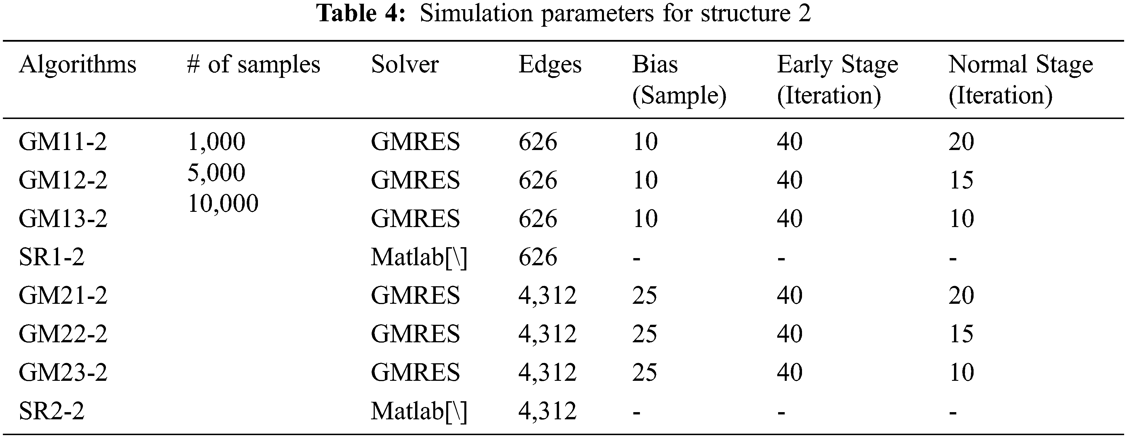
The test setting is as follows; The number of samples used in the simulation is 1,000, 5,000, and 10,000, the bias is 10 and 25, and iterations for the early stage are 40, and iterations for the normal stage are 20, 15, and 10. The number of samples affects the frequency interval, and the more samples, the shorter the analysis interval. ‘Bias’ refers to the interval of the front part that is calculated in advance to alleviate the problem that the early stage solution fluctuates; for example, in the case of bias 10, the actual simulation starts as early as the interval of 10 samples. In addition, the ‘early stage iterations’ means the number of iterations for iterative solver convergence during the early stage, and the higher the number of iterations, the higher the accuracy. The ‘normal stage iterations’ refers to the number of iterations for iterative solver convergence in the actual section after the early stage. Early stage iterations are chosen higher (that is, 40) than the normal stage to alleviate the convergence issues in cold-start situation. Since the normal stage corresponds to most of the simulation, the setting of the normal stage directly affects the analysis speed. The smaller the value of iterations, the faster the simulation speed but the lower the accuracy. The normal stage does not require a large iteration for a convergence compared to the early stage, so pre-determined values 10, 15, and 20 were adopted. An example of proposed solver implementation under Matlab is E = gmres(K, b, [], [], iteration, P, I, E).
The analysis was conducted by changing the number of edges that directly affect accuracy when analyzing FEM. The purpose of this simulation test is to find the most efficient parameter setting, and the simulation setting for the above conditions is listed in the following Tabs. 3 and 4.

4.2 F Simulation Results and Discussion
Figs. 5 and 7 are S11 parameters for structure 1. On the other hand, Figs. 6 and 8 are absolute errors between in-house code results and HFSS results. As the number of sampling points and normal iterations increases, the in-house results become similar to those of HFSS. In Tab. 4, it can be seen that in-house code using GMRES is more advantageous than Matlab’s backslash in terms of simulation speed when it is more than 5,000 samples and less than 15 normal iterations. For the accuracy, all of the in-house cases show acceptable accuracy in terms of an engineering perspective.

Figure 5: S11 parameter for structure 1 (edge #: 1,427)

Figure 6: Absolute error for structure 1 (edge #: 1,427)

Figure 7: S11 parameter for structure 1 (edge #: 5,112)

Figure 8: Absolute error for structure 1 (edge #: 5,112)
Similar to the previous case, Figs. 9 and 11 are S11 parameters for structure 2. On the other hand, Figs. 10 and 12 are absolute errors between in-house code results and HFSS results. Like the previous case, it can be seen that as the number of samples, edges, and basic iterations increases, the in-house result becomes similar to that of HFSS. Unlike the previous results, when analyzed using 626 edges, it can be seen that in-house code using GMRES is more advantageous in simulation speed than Matlab’s backslash in all cases. For 4,312 edges, in-house code using GMRES is more advantageous than Matlab’s backslash when more than 5,000 samples and less than 15 normal iteration cases.
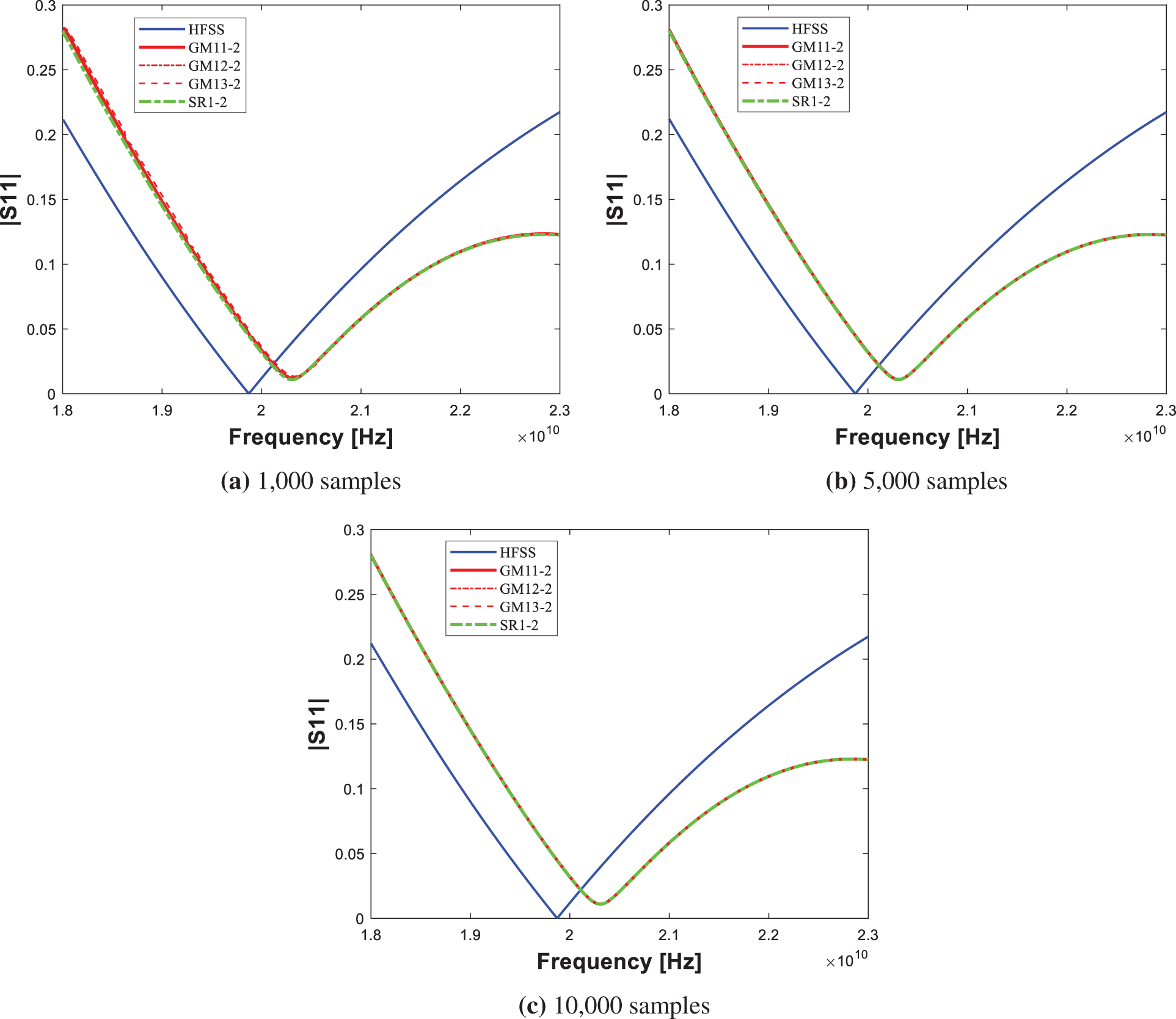
Figure 9: S11 parameter for structure 2 (edge #: 626)

Figure 10: Absolute error for structure 2 (edge #: 626)

Figure 11: S11 parameter for structure 2 (edge #: 4,312)
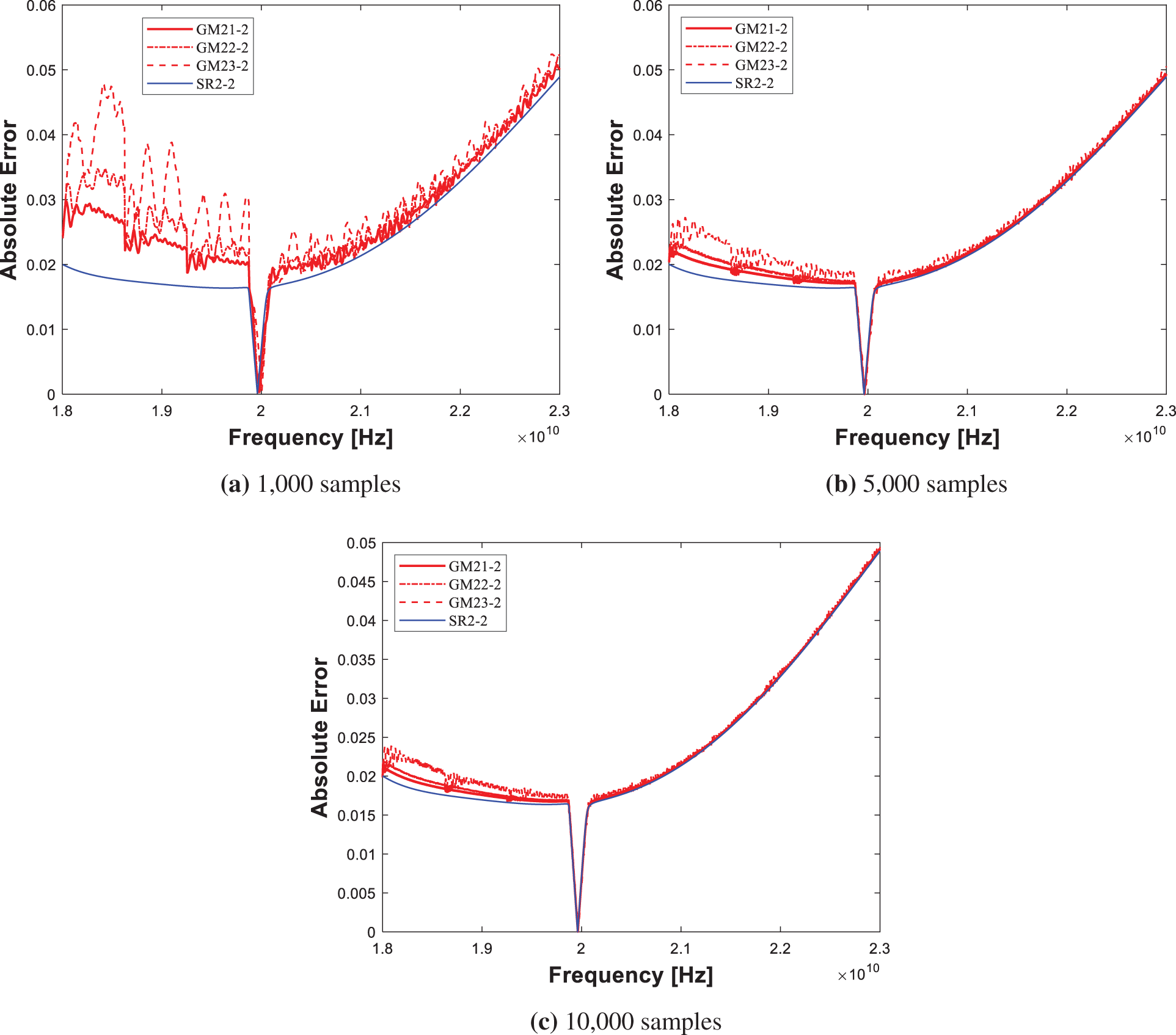
Figure 12: Absolute error for structure 2 (edge #: 4,312)
It can be observed that the more sampling intervals and the fewer edges, the stronger the proposed scheme is. For the case of GM13-2, the simulation speed is about 2.7 times faster even though the same RMSE as the Matlab’s backslash is shown. Also, all cases demonstrate good accuracy. RMSE, RMSPE and elapsed time for structure 1/RMSE, RMSPE and elapsed time for structure 2 are shown in Tabs. 5 and 6, respectively.


In this paper, a new parallel iterative FEM solver for the S parameter is implemented for 3-D inhomogeneous waveguide structures. Previous conventional iterative solvers are hard to be applied because the frequency domain system matrix is complex-numbered and indefinite. The proposed scheme allows applying a gmres solver with a good initial guess and a preconditioner over parallel processing (spmd) to this type of FEM system. Simulations were conducted by changing the number of sampling intervals, edge, and normal stage iteration. The less the difference between the consecutive solutions and/or the less the edge can be used, the more the proposed scheme shows its strength. In the normal stage, the accuracy increases as the higher the iterations are used, but the simulation time increases proportionally.
It is also noted that parallelization was performed only on the proposed scheme, so Matalb’s backslash is not parallelized in the paper. Thus, parallelized backslash is likely to show better performance than the current proposed scheme. In the future, the variation of the previous solution input to the iterative solver, e.g., the average of the previous two solutions, can be further tested to demonstrate the proposed scheme. Also, we can further try larger unknown cases to deal with realistic on-chip structures.
Funding Statement: This work was supported by Institute of Information & communications Technology Planning & Evaluation (IITP) grant funded by the Korea government (MSIT) (No. 2019-0-00098, Advanced and Integrated Software Development for Electromagnetic Analysis). This work was also supported by Research Assistance Program (2021) in the Incheon National University.
Conflicts of Interest: The authors declare that they have no conflicts of interest to report regarding the present study.
References
1. J. M. Jin, Theory and Computation of Electromagnetic Fields. 2nd ed., Hoboken, NJ, USA: Wiley-IEEE Press, 2015. [Online]. Available: https://www.wiley.com/en-us/Theory + and + Computation + of + Electromagnetic + Fields + 2nd + Edition-p-9781119108047. [Google Scholar]
2. D. K. Cheng, Field and Wave Electromagnetics. 2nd ed., Boston, MA, USA: Addison-Wesley, 1989. [Online]. Available: https://www.pearson.com/en-us/subject-catalog/p/field-and-wave-electromagnetics/P200000003223/9780201128192. [Google Scholar]
3. D. B. Davidson, Computational Electromagnetics for RF and Microwave Engineering. 2nd ed., Cambridge, UK: Cambridge University Press, 2014. [Online]. Available: https://www.cambridge.org/core/books/computational-electromagnetics-for-rf-and-microwave-engineering/F4D81416FA6CABDC99B893676E282D2D. [Google Scholar]
4. J. M. Jin, The Finite Element Method in Electromagnetics. 3rd ed., Hoboken, NJ, USA: Wiley-IEEE Press, 2014. [Online]. Available: https://www.wiley.com/en-us/The + Finite + Element + Method + in + Electromagnetics + 3rd + Edition-p-9781118571361. [Google Scholar]
5. Z. Lou and J. M. Jin, “A novel dual-field time-domain finite-element domain-decomposition method for computational electromagnetics,” IEEE Transactions on Antennas and Propagation, vol. 54, no. 6, pp. 1850–1862, 2006. [Google Scholar]
6. W. Lee and D. Jiao, “Symmetric positive-definite representation of frequency-domain finite-element system matrix for efficient electromagnetic analysis,” in Proc. IEEE APSURSI, Fajardo, PR, USA, pp. 1121–1122, 2016. [Google Scholar]
7. W. Lee, M. Kim and J. Park, “Speed-up of the matrix computation on the ridge regression,” KSII Transactions on Internet and Information Systems, vol. 15, no. 10, pp. 3482–3497, 2021. [Google Scholar]
8. M. Kim and W. Lee, “Adaptive success rate-based sensor relocation for IoT applications,” KSII Transactions on Internet and Information Systems, vol. 15, no. 9, pp. 3120–3137, 2021. [Google Scholar]
9. Y. Altman, Accelerating MATLAB Performance. 1st ed., Boca Raton, FL, USA: CRC Press, 2015. [Online]. Available: https://www.routledge.com/Accelerating-MATLAB-Performance-1001-tips-to-speed-up-MATLAB-programs/Altman/p/book/9781482211290. [Google Scholar]
10. O. Ozgun and M. Kuzuoglu, MATLAB-based Finite Element Programming in Electromagnetic Modeling. 1st ed., Boca Raton, FL, USA: CRC Press, 2018. [Online]. Available: https://www.routledge.com/MATLAB-based-Finite-Element-Programming-in-Electromagnetic-Modeling/Ozgun-Kuzuoglu/p/book/9781498784078. [Google Scholar]
11. S. Koric and A. Gupta, “Sparse matrix factorization in the implicit finite element method on petascale architecture,” Computer Methods in Applied Mechanics and Engineering, vol. 302, no. 1, pp. 281–292, 2016. [Google Scholar]
12. H. A. van der Vorst, “A fast and smoothly converging variant of bi-cg for the solution of nonsymmetric linear systems,” SIAM Journal on Scientific and Statistical Computing, vol. 13, no. 2, pp. 631–644, 1992. [Google Scholar]
13. Y. Saad and M. H. Schultz, “GMRES: A generalized minimal residual algorithm for solving nonsymmetric linear systems,” SIAM Journal on Scientific and Statistical Computing, vol. 7, no. 3, pp. 856–869, 1986. [Google Scholar]
14. S. Ye, Y. Lin, L. Xu and J. Wu, “Improving initial guess for the iterative solution of linear equation systems in incompressible flow,” Mathematics, vol. 8, no. 1, pp. 1–20, 2020. [Google Scholar]
Cite This Article
 Copyright © 2023 The Author(s). Published by Tech Science Press.
This work is licensed under a Creative Commons Attribution 4.0 International License , which permits unrestricted use, distribution, and reproduction in any medium, provided the original work is properly cited.
 Downloads
 Citation Tools