
 Submit a Paper
 Propose a Special lssue
 Open Access
ARTICLE

Power-Sharing Enhancement Using Harmonized Membership Fuzzy Logic Droop Control Based Micro-Grid
School of Electrical Engineering, Vellore Institute of Technology, Vellore, 632014, Tamilnadu, India
* Corresponding Author: J. Belwin Edward. Email:
Intelligent Automation & Soft Computing 2023, 36(2), 1395-1415. https://doi.org/10.32604/iasc.2023.028970
Received 22 February 2022; Accepted 24 June 2022; Issue published 05 January 2023
 View Full Text
 Download PDF
Abstract
The contribution of Renewable Energy Resources (RER) in the process of power generation is significantly high in the recent days since it paves the way for overcoming the issues like serious energy crisis and natural contamination. This paper deals with the renewable energy based micro-grid as it is regarded as the apt solution for integrating the RER with the electrical frameworks. As the fixed droop coefficients in conventional droop control approaches have caused various limitations like low power-sharing and sudden drops of grid voltage in the Direct Current (DC) side, the Harmonized Membership Fuzzy Logic (MFL) droop control is employed in this present study. This proposed droop control for the hybrid PV-wind-battery system with MFL assists in achieving proper power-sharing and minimizing Total Harmonic Distortion (THD) in the emergency micro-grid. It eradicates the deviations in voltage and frequency with its flexible and robust operation. The THD is reduced and attains the value of 3.1% compared to the traditional droop control. The simulation results of harmonized MFL droop control are analogized with the conventional approaches to validate the performance of the proposed method. In addition, the experimental results provided by the Field Programmable Gate Array (FPGA) based laboratory setup built using a solar photovoltaic (PV) and wind Permanent Magnet Synchronous Generator (PMSG) reaffirms the design.Keywords
The extensive usage of traditional energy sources and fossil fuel has increased the emission of greenhouse gases like CO2 and CH4, which spoils the environment to a greater extent. Because of these reasons, the demand of RER like wind, solar and thermal energies has been increased in the current scenario. The combination of PV, wind, battery storage and fuel cells in the inverter-based distributed generators (DGs) has gained much attention. In the integration of DGs, the Micro-grid plays a vital role as it includes various advantageous impacts like eco-friendliness, high efficiency, good power-sharing capacity and flexible operation [1,2]. The operating mode of micro-grid is subdivided into grid-tied and islanded modes. In normal conditions, the micro-grid is connected to the main distribution grid. When the disturbances or faults are occurred in the main DG, the main network forces the micro-grid to operate in the emergency mode [3]. It is highly complex to control the electrical power network of micro-grid since the inverter-based DGs is connected to the grid [4]. In the micro-grid, power electronic converter is crucial because it allow RE resources and energy storage devices to be connected to micro-grids. This allows adjustable control of real and reactive electricity input into the micro-grid as well as Maximum Power Point Tracking (MPPT) of solar PV and wind turbines (WTs). An interface converter connects an Alternating Current (AC) micro-grid and a DC micro-grid to form a hybrid AC/DC micro-grid. When the utility grid is linked to the AC bus, the micro-grid operates in grid-connected mode and when the utility grid is unplugged, it operates in stand-alone mode. It is used in a DC micro-grid to convert AC or DC power with varying voltages into DC electricity with the same voltage as the DC micro-DC grid’s bus [5]. Power electronic converters are classed as DC/DC or DC/AC converters based on the input and output power. When a micro-grid is connected to the utility grid, converters in the micro-grid function in grid-connected mode, supplying real and reactive electricity to the micro-grid from DGs [6]. When a micro-grid is disconnected from the utility grid in an emergency mode, converters in the micro-grid function in grid-connected mode to provide AC voltage and frequency support [7]. According to the status of the micro-grid and DGs, converters in the micro-grid has to flip between different operating modes [8].
The control technique of micro-grid faces more challenges like power quality problems, stability, harmonic issues, and so on. In order to tackle these issues, droop control approaches are developed over decades. Conventional droop control achieves power sharing by the behaviour of synchronous generators. The accuracy of power sharing is improved by larger droop gain values but the deviation of voltage and frequency increases [9]. In addition, conventional droop control approaches face poor reactive power sharing, unbalanced harmonic current sharing and sluggish dynamic response [10]. Since the conventional droop control approaches have operated under the basic droop coefficient, the error is inherent in these methods. To limit the error and to upgrade the transient response, several droop control methodologies are introduced in the recent decades, which aid in minimizing the fluctuations of voltage and frequency [11–13]. The virtual flux droop control is presented by sharing the power accuracy between the active and reactive powers [14,15]. An angle droop controller is employed to limit the recurrence deviation by drooping the phase angle of inverter output voltage. The adaptive droop control is utilized, in which the droop coefficient is adjusted by using the characteristics of RERs [16]. In spite of having various advantages, the application of the existing approaches is limited since these approaches fail to consider the THD at Point of Common Coupling (PCC). In [17], the resistive active power filter control is employed, which has many acceptable impacts. However, it is very difficult to maintain this system as it has the complex structure. The power-sharing is improvised with the help of the resistive-inductive virtual impedance method [18–20]. It regulates the output impedance of the inverters by calculating the output current and voltage. Due to the output filter of the surge impedances and the variations of time, this approach is not practically applicable.
The Harmonic virtual impedance for emergency micro-grid is utilized in various approaches to transfer the harmonic power between the inverter interfaced DGs [21]. It is used for rectifying the power quality problems in the parallel-connected DGs [22]. The droop control has some stability problems like lack of proper sharing, voltage deviation, harmonic unbalance and power variations. To rectify these limitations, the line impedance and virtual output impedance are preferred in the conventional droop controllers, which provide a frequency restoration loop [23,24]. In the conventional droop controllers, the Fuzzy Logic Control (FLC) is utilized to elevate the transient response [25].
The present paper proposes a RER based emergency micro-grid using harmonized MFL droop control. The chief objective of this study is to design an MFL controller by using a Mamdani design model. The primary droop control and harmonic virtual impedance are used to eradicate the surge impedance and the harmonics at PCC. The exploration of micro-grid design is presented in Section 2, the harmonized droop control concept and harmonic virtual impedance are presented in Section 3. The proposed MFL with harmonized droop control is elucidated in Section 4 and the results of the proposed work are validated in Section 5. Eventually, the summary of this study is provided in Section 6.
2 Exploration of Micro-Grid Structural Design
This paper proposes the harmonized MFL droop control based micro-grid, in which three different DGs like solar PV, wind and battery energy storage system (BESS) are utilized as illustrated in Fig. 1. The permanent magnet synchronous generator (PMSG) is utilized in the wind energy system to eliminate the uncertainties of wind power generation. In normal conditions, the micro-grid is directly linked to the main grid since there is no occurrence of faults or deviations. During the occurrence of fault in the main grid, the micro-grid is switched from the ordinary mode to emergency mode to deliver uninterrupted power-sharing.

Figure 1: Exploration of micro-grid structural design
The droop control operation is highly mandatory for the power-sharing of DGs in emergency mode. The present paper analyzes the emergency operation on the inverter-based DG with droop control technique. To regulate the power-sharing of DGs, the harmonized MFL droop control is employed in this study. In addition, the optional control using proportional integral (PI) controller is used to eliminate the fluctuations in voltage and frequency. For confiscating the influence of line impedance, the compensated frequency and voltage are then fed to the virtual impedance loop. Hence, the stability and power-sharing of the system is enhanced with the assistance of this approach.
A PV cell is regarded as the fundamental unit, which converts the solar irradiation into DC power by absorbing the electrons and photons in the sunlight. In this present study, one diode model is used since it is simple and accurate. Fig. 2 illustrates the equivalent circuit of one diode model. The saturation current of the diode [26–28] is given as,

Figure 2: Equivalent circuit of one diode model
The mathematical formulation of one diode model is specified as,
Wind power is used to generate torque in the PMSG wind turbine. The torque is delivered to the generator rotor via the generator shaft. The difference between the mechanical torque generated by the WT and the electrical torque generated by the generator determines whether the mechanical system accelerates, decelerates, or stays at a constant speed [29]. As it lacks a gearbox and excitation elements, the PMSG is employed in wind power conversion systems. The WT converts wind kinetic energy to mechanical energy with the help of the aerodynamic force generated by the rotor blades. The value of Pm of the aerodynamic power equation can be stated as,
Here, ρ is the air density,
The tip speed ratio λ is the connection between the wind speed and the rotor speed is given by,
Where,
It is feasible to calculate the value of the torque Tm operating on the shaft using the value of the rotation.
PMSG’s generator model is totally implemented in dq-coordinates. It denotes that the model has no AC states [30].
The torque formulae for PMSG as well as the output active power of PMSG are as follows:
The d-axis and q-axis current and voltages respectively, are represented by isd, isq, usd, and usq. The generator’s electrical angular frequency is
2.3 FLC for MPPT from PV System
The maximum power extraction for varying temperature and input irradiance conditions is performed by the FLC logic which is efficient when compared to conventional algorithms for complicated approaches. During fuzzification, the input crisp data is converted to fuzzy set using linguistic variables and membership functions. Further IF-THEN rules are proposed with appropriate conditions and conclusions. Finally, defuzzification is performed for the control of non-fuzzy values.
Fig. 3 represents the MPPT control approach for PV system. The maximum power point is maintained with zero value of error signal

Figure 3: MPPT for PV system
Here
3 The Concept of Droop Control and Harmonic Virtual Impedance
As the conventional droop control approaches have failed to eradicate the deviations in voltage and frequency, the harmonized MFL droop control is proposed in this paper. A Pulse Width Modulation (PWM) inverter is used in this approach. Initially, the harmonized MFL droop control acts as the primary controller, which assists in enhancing the power-sharing ability of the DGs. Though the power-sharing is enhanced, the deviation of voltage and frequency is not eliminated. Thus, the secondary optional controller is utilized to fix all the voltage and current loop controllers. The P/Q theory is used to calculate the frequency and duty ratio of primary and optional controllers.
In accordance with the current analysis, the injected power of the utility grid is given as,
The real and reactive powers of the DG are specified as,
In
In conditions (18) and (19), the difference between the phase angle (
The relation between voltage and reactive power is given by,
The reference voltage, which is sent through the virtual impedance loop is explained as,
The virtual harmonic impedance is given by,
The harmonic virtual impedance of DG at the PCC is given by,
Primary controller comprises of inner loops of DC/DC converters and AC/DC converters whereas droop control consists of basic power-sharing in power electronic converters. Inner loops regulate the AC current in synchronous rotating frame in AC/ DC converters using Voltage Source Inverter (VSI) based on vector control (dq-frame). The linear controllers modify current in the dq domain and output dq voltage needs after converting observed currents from three phase stationary frame to synchronous rotating frame. The block diagram of the inner loop of voltage and current regulation is shown in Fig. 4.

Figure 4: Block diagram of inner loop control
As a result, the VSI is capable to control real and reactive power. The voltage and current control modes are two different types of DC/DC converters. The voltage control mode establishes a voltage reference and functions as a variable voltage source whereas the current control mode acts as a controllable current source. The output current is regulated to match the reference value.
The ability of power-sharing is enhanced by the primary control but it fails to eradicate the deviations in frequency and voltage. To eliminate this fluctuation, the secondary control is instigated in this approach. The ultimate aim of this controller is to re-establish the voltage and frequency level with the aid of the droop control operation. As all the DG units are in a consistent level, the system is operated by the reference value through the DG units. The common multi-agent system is expressed as,
4 Proposed Harmonized MFL Droop Control Method
The harmonized MFL droop control is employed to improvise the power-sharing of DGs in real time. As adaptive PI controllers are hard to calculate multi-input variables with multi-objective control, the harmonized MFL is used in technical applications. It operates based on equal power-sharing as,
Here, P1, P2 are the s power output of RERs
During the occurrence of sudden power decrease in the RERs, the harmonized droop coefficient has to be tuned to compensate the output power. The power deviation (∆P), which reflects power fluctuation, and the power balance (η) that represents the stability and power-sharing of the emergency micro-grid are the two most important factors in choosing a droop coefficient (mp). It is possible to design MFL by requiring the power deviation (∆P), power balance (η), updating the droop coefficient (mp). Because of its simplicity, the triangular Membership Function (MF) is commonly employed in fuzzy logic systems. The result of triangle MF is almost certainly a point value, in which a given input value correlates to a different inaccurate output value. In contrast, the trapezoidal MF allows different input intervals to correspond to different outcomes that are ideal for droop coefficient regulation because it is impossible to frequently adjust the droop coefficient. The design of harmonized MFL droop control is shown in Fig. 5.

Figure 5: Design of harmonized MFL droop control method
Two input variables, such as power deviation (∆P) and power balance factor (η), are chosen in this diagram. The expression for the power balance factor (η), is:
The expression of power deviation (∆P) is given by,
The linguistic variables are noted as negative high (NH), negative medium (NM), negative low (NL), zero (Z), positive low (PL), positive medium (PM) and positive high (PH). For example, the trapezoidal MF for power deviation (∆P) of negative high (NH) is written as,
The proposed fuzzy inference system is represented in Fig. 6. It has two input variables (power deviation (∆P) and power balance factor (η)) and one output variable (droop coefficients (mp)).
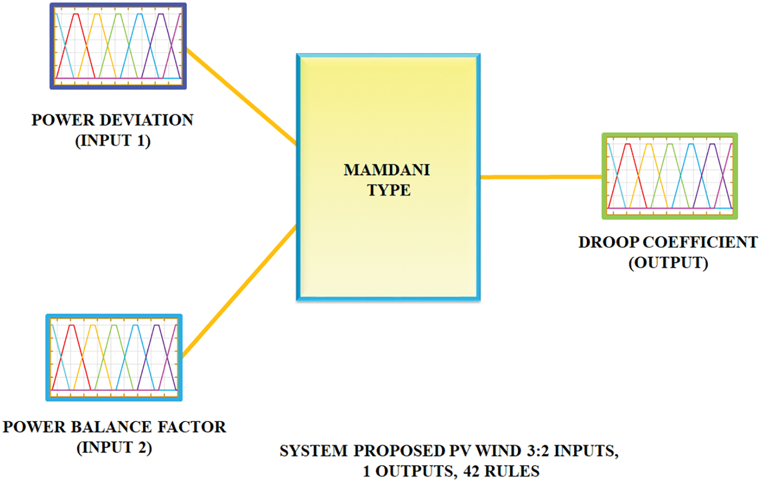
Figure 6: Proposed fuzzy logic inference system
With the aid of fuzzy inference system, the defuzzification
From these figures, the MF values for the input variables of power deviations are noted as
The Output variable of droop coefficient MF is clearly portrayed in Fig. 7. Fig. 8 shows the control surface of the proposed MFL, which summarizes the behavior of the fuzzy inference system, where droop coefficient is adjusted based on the power balance factor (η) and power deviation (∆P). It makes evident that the power deviation (∆P) takes an important role into the performance of the system that is why the fuzzy inference system tries to reduce the power deviation (∆P) but it does not try to eliminate the power deviation (∆P).

Figure 7: Output variable of droop coefficient MF

Figure 8: The surface of MFL
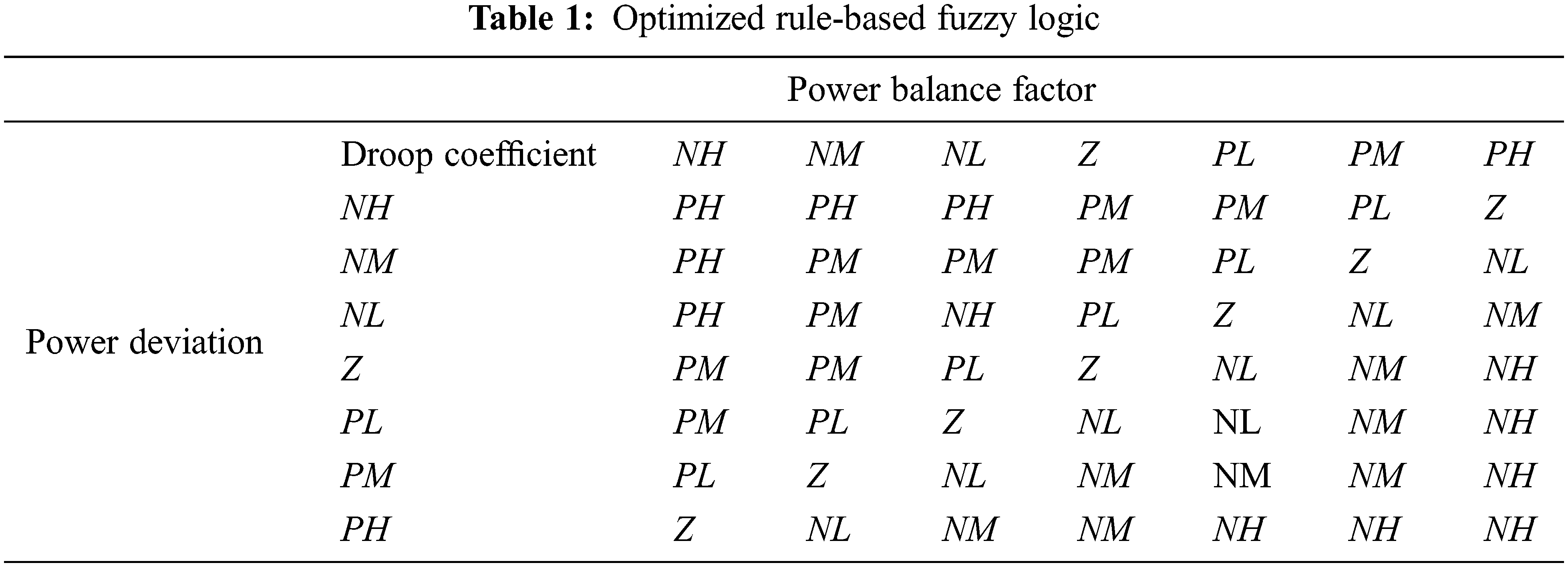
The droop coefficient (mp) is increased or lowered depending on the power balance (η) and the power deviation (∆P). The droop coefficient (mp) has to be reduced when the power balance (η) is low so that the RER can deliver higher power output since the output power can be as high as the maximum value. Otherwise, the system may be stable when the power balance (η) is high, and the droop coefficient (mp) should be changed mostly based on the power deviation (∆P). When the power balance (η) is in the middle (0.4 < η < 0.6), both of these parameters will influence the mp adjustment. Tab. 1 denotes the rules of fuzzy inference system.
By substituting the Eq. (33) in (22), it is written as,
Therefore, it is applied to regulate the output of the real power-sharing.
A harmonized MFL droop control based micro-grid system is introduced in this work for enhancing the power-sharing of DGs in the emergency mode. The implementation of PMSG aids in eliminating the disruptions in the process of wind power generation whereas the implementation of PI controller assists in excluding the oscillations in voltage and frequency. The entire system is validated in MATLAB simulink and the outcomes are evidently portrayed in the subsequent section. The parameter specifications are listed out in Tab. 2.

In consideration with the irradiation level, the PV output voltage gets varied because the fluctuations in the solar irradiations greatly affect the process of power generation. Fig. 9 clearly depicts the oscillations in the irradiance level of solar energy.

Figure 9: Irradiance of PV
The aforementioned waveforms in Fig. 10 portrays the output current and voltage of converter. The waveforms validate that the initial fluctuations in the output voltage is eliminated after

Figure 10: Performance of system under converter ratings (a) Output voltage (b) Output current
The proposed approach enables the constant regulation of DC link voltage by the fuzzy MPPT control approach and the link voltage is maintained stable as portrayed in Fig. 11. Thus, it is validated that a constant voltage of

Figure 11: DC link voltage
The waveforms in Fig. 12 have highlighted the output voltage of both the PMSG and wind rectifier and it is proven from this figure that the voltage of PMSG differs from

Figure 12: (a) Output voltage of PMSG (b) Wind rectifier
The waveform representing the inverter output voltage is evidently illustrated in Fig. 13 and it is noted from this figure that the waveform gets fluctuated in the initial stage but it turns as constant and the voltage of

Figure 13: Performance of the proposed harmonized MFL droop control with inverter output voltage
The waveforms indicating the current and voltage of load are significantly displayed in Fig. 14, which shows the current in transition from grid-connected to emergency mode and voltage in transition from emergency mode to grid-connected mode. Also highlighted that the current gets varied from

Figure 14: Performance of (a) Current in transition from grid-connected to emergency mode (b) Voltage in transition from emergency mode to grid-connected mode
The compensation of real and reactive power is remarkably achieved in this study, which is evidently signified in Fig. 15. The initial disruptions in the reactive power is constantly retained as portrayed in the waveform whereas the constant real power is achieved without any oscillations.

Figure 15: Real and reactive power-sharing using proposed harmonized MFL droop control
The ultimate motive of minimizing the THD value is remarkably achieved in this study, which is significantly highlighted in Fig. 16. The contribution of both the traditional and proposed harmonized droop control in minimizing the THD is validated through this Figure, which shows that the total THD of

Figure 16: THD at proposed droop control
The experimental validation of this entire study is significantly provided in the subsequent section and the hardware prototype of this work is clearly portrayed in Fig. 17. The hardware program is carried out in Spartan 6E controller and the outcomes are provided with prior validation.

Figure 17: Hardware prototype
Based on the irradiation changes, the PV delivers the low output voltage with fluctuations as highlighted in Fig. 18 and this output is fed as the input of the converter, which assists in maximizing the voltage in a wider range.

Figure 18: Output voltage of PV with fluctuations
The converter generates optimum output voltage and the voltage is constantly maintained without any oscillations, which is significantly portrayed in Fig. 19. Through the figure, it is validated that the contribution of the proposed converter in the process of maximizing the link voltage is remarkably high.

Figure 19: Test results for converter output voltage
As depicted in Fig. 20, the output of PMSG is attained with disruptions in consideration with the wind speed and so the fluctuations in this output have to be constantly maintained for receiving the optimal outcomes. The disruptions in the wind waveform have to be eliminate to enhance the overall operation of the system.

Figure 20: Output voltage PMSG with disruptions
The significance this PWM rectifier in the process of regulating the PMSG output is highly remarkable because it eliminates all the oscillation in the output and retained it as constant as highlighted in Fig. 21. From the Figure, it is noted that the rectifier delivers the stable output without any disruptions, which in turn enhances the overall functioning of the system.

Figure 21: Test results for rectifier output voltage
The waveform indicating the VSI output is significantly depicted in Fig. 22, which validate that the obtained outcome is highly optimal since it compensates the grid voltage without any disruptions. Thus, the enhanced output of VSI is acquired through the implementation of the introduced approach.

Figure 22: Grid voltage occurs without disruptions
The waveforms representing the voltage and current are evidently portrayed in Fig. 23, shows the voltage in transition from emergency mode to grid-connected mode and current in transition from grid-connected mode to emergency mode. This can significantly proves that both the current and voltage are constantly retained with the assistance on the proposed methodology. The waveforms are attained without any fluctuations, which clears that the interruption free outputs are achieved for providing optimal operation.

Figure 23: Experimental results of (a) Voltage in transition to grid-connected mode (b) Current in transition to emergency mode
The process of minimizing the THD value is regarded as one of the prime objectives of this study, which is effectively accomplished with the aid of the proposed approach since it delivers less THD value of 3.6% as specified in Fig. 24. The comparative evaluation is carried out between the introduced control method and other approaches, which evidently validates that the MFL based harmonized droop control effectively performs in the THD minimization process since it delivers lesser THD value of

Figure 24: FFT plot of THD reduction using proposed harmonized MFL droop control

Figure 25: Comparison of THD under different droop control methods
The implementation Harmonized MFL based droop control in the micro-grid system for maximizing the capability of power-sharing and stability as it is enveloped with multiple beneficial measures. The simulation and experimental results show the improvement of power-sharing with droop control among the DG units and the following observations have been noted in the analysis.
• Regulating the output power of the RE sources in consideration with the load fluctuations in PCC.
• The implementation of PMSG is preferred for eliminating the disruptions in the generation of wind power.
• The oscillations in the voltage and frequency are minimized with the aid of PI controller.
• The THD level is 3.1%, which falls within the acceptable limit which is reduced compared to the traditional droop control.
Therefore, the control strategy has been simulated, which validates that the feasibility of the proposed droop control is highly effective as it delivers optimal power-sharing with less THD.
Funding Statement: The authors received no specific funding for this study.
Conflicts of Interest: The authors declare that they have no conflicts of interest to report regarding the present study.
References
1. X. Zhou, F. Tang, P. C. Loh, X. Jin and W. Cao, “Four-leg converters with improved common current sharing and selective voltage-quality enhancement for islanded microgrids,” IEEE Transactions on Power Delivery, vol. 31, no. 2, pp. 522–531, 2016. [Google Scholar]
2. H. Farhangi, “The path of the smart grid,” IEEE Power and Energy Magazine, vol. 8, no. 1, pp. 18–28, 2010. [Google Scholar]
3. R. M. Kamel, “Standalone microgrid power quality improvement using inertia and power reserves of the wind generation systems,” Renewable Energy, vol. 97, no. 1, pp. 572–584, 2016. [Google Scholar]
4. T. L. Vandoorn, J. D. Kooning, B. Meersman and L. Vandevelde, “Voltage-based droop control of renewables to avoid on-off oscillations caused by over voltages,” IEEE Transactions on Power Delivery, vol. 28, no. 2, pp. 845–854, 2013. [Google Scholar]
5. J. Li, Y. Liu, L. Wu, “Optimal operation for community-based multi-party microgrid in grid-connected and islanded modes,” IEEE Transactions on Smart Grid, vol. 9, no. 2, pp. 756–765, 2018. [Google Scholar]
6. F. Mandrile, E. Carpaneto and R. Bojoi, “Grid-feeding inverter with simplified virtual synchronous compensator providing grid services and grid support,” IEEE Transactions on Industry Applications, vol. 57, no. 1, pp. 559–569, 2021. [Google Scholar]
7. S. Yazdani, M. Ferdowsi, M. Davari and P. Shamsi, “Advanced current-limiting and power-sharing control in a PV-based grid-forming inverter under unbalanced grid conditions,” IEEE Journal of Emerging and Selected Topics in Power Electronics, vol. 8, no. 2, pp. 1084–1096, 2020. [Google Scholar]
8. J. Hmad, A. Houari, H. Trabelsi and M. Machmoum, “Fuzzy logic approach for smooth transition between grid-connected and stand-alone modes of three-phase DG-inverter,” Electric Power Systems Research, vol. 175, no. 1, pp. 105892, 2019. [Google Scholar]
9. Y. Sun, X. Hou, J. Yang, H. Han, M. Su et al., “New perspectives on droop control in AC microgrid,” IEEE Transactions on Industrial Electronics, vol. 64, no. 7, pp. 5741–5745, 2017. [Google Scholar]
10. Z. Afshar, M. Mollayousefi, S. M. T. Bathaee, M. T. Bina and G. B. Gharehpetian, “A novel accurate power sharing method versus droop control in autonomous microgrids with critical loads,” IEEE Access, vol. 7, pp. 89466–89474, 2019. [Google Scholar]
11. L. P. Sampaio, M. A. G. Brito, G. A. E. Melo and C. A. Canesin, “Grid-tie three phase inverter with active power injection and reactive power compensation,” Renewable Energy, vol. 85, no. 3, pp. 854–864, 2016. [Google Scholar]
12. S. Eren, M. Pahlevani, A. Bakhshai and P. Jain, “An adaptive droop DC-bus voltage controller for a grid connected voltage source inverter with LCL filter,” IEEE Transactions on Power Electronics, vol. 30, no. 2, pp. 547–560, 2015. [Google Scholar]
13. H. Han, Y. Sun, M. Su and J. M. Guerrero, “An improved droop control strategy for reactive power sharing in islanded microgrid,” IEEE Transactions on Power Electronics, vol. 30, no. 6, pp. 3133–3141, 2015. [Google Scholar]
14. J. Hu, J. Zhu, D. G. Dorrell and J. M. Guerrero, “Virtual flux droop method–A new control strategy of inverters in microgrids,” IEEE Transactions on Power Electronics, vol. 29, no. 9, pp. 4704–4711, 2014. [Google Scholar]
15. R. Majumder, B. Chaudhuri, A. Ghosh, R. Majumder, G. Ledwich et al., “Improvement of stability and load sharing in an autonomous microgrid using supplementary droop control loop,” IEEE Transactions Power System, vol. 25, no. 2, pp. 796–808, 2010. [Google Scholar]
16. N. L. Diaz., J. C. Vasquez and J. M. Guerrero, “A communication-less distributed control architecture for islanded microgrids with renewable generation and storage,” IEEE Transactions on Power Electronics, vol. 33, no. 3, pp. 1922–1939, 2018. [Google Scholar]
17. Z. Zeng, H. Yi, H. Zhai, F. Zhuo and Z. Wang, “Harmonic power sharing and PCC voltage harmonics compensation in islanded microgrids by adopting virtual harmonic impedance method,” in IECON–43rd Annual Conf. of the IEEE Industrial Electronics Society, Beijing, China, pp. 263–267, 2017. [Google Scholar]
18. A. Micallef, M. Apap, C. S. Staines, J. M. Guerrero and J. C. Vasquez, “Reactive power sharing and voltage harmonic distortion compensation of droop controlled single phase islanded microgrids,” IEEE Transactions on Smart Grid, vol. 5, no. 3, pp. 1149–1158, 2014. [Google Scholar]
19. J. Guerrero, J. Matas, L. G. D. V. D. Vicuna, M. Castilla and J. Miret, “Wireless-control strategy for parallel operation of distributed-generation inverters,” IEEE Transactions on Industrial Electronics, vol. 53, no. 5, pp. 1461–1470, 2006. [Google Scholar]
20. M. Savaghebi, A. Jalilian, J. C. Vasquez and J. M. Guerrero, “Secondary control scheme for voltage unbalance compensation in an islanded droop-controlled microgrid,” IEEE Transactions on Smart Grid, vol. 3, no. 2, pp. 797–807, 2012. [Google Scholar]
21. P. Sreekumar and V. Khadkikar, “A new virtual harmonic impedance scheme for harmonic power sharing in an islanded microgrid,” IEEE Transactions on Power Delivery, vol. 31, no. 3, pp. 936–945, 2016. [Google Scholar]
22. J. R. Perez, A. R. Cabero and M. Prodanovic, “Harmonic virtual impedance design for parallel-connected grid-tied synchronverters,” IEEE Journal of Emerging & Selected Topics in Power Electronics, vol. 7, no. 1, pp. 493–503, 2019. [Google Scholar]
23. Y. Zhu, F. Zhuo, F. Wang, B. Liu, R. Gou et al., “A virtual impedance optimization method for reactive power sharing in networked microgrid,” IEEE Transactions on Power Electronics, vol. 31, no. 4, pp. 2890–2904, 2016. [Google Scholar]
24. Z. Lyu, Q. Wei, Y. Zhang, J. Zhao and E. Manla, “Adaptive virtual impedance droop control based on consensus control of reactive current,” Energies, vol. 11, no. 7, pp. 1801, 2018. [Google Scholar]
25. Y. V. P. Kumar and R. Bhimasingu, “Fuzzy logic based adaptive virtual inertia in droop control operation of the microgrid for improved transient response,” in EEE PES Asia-Pacific Power and Energy Engineering Conf. (APPEEC), Bangalore, India, pp. 1–6, 2017. [Google Scholar]
26. R. W. Mosobi, T. Chichi and S. Gao, “Modeling and power quality analysis of integrated renewable energy system,” in Eighteenth National Power Systems Conf. (NPSC), Guwahati, India, pp. 1–6, 2014. [Google Scholar]
27. A. Verma, B. Singh and D. T. Shahani, “Grid interfaced solar photovoltaic power generating system with power quality improvement at AC mains,” in IEEE Third Int. Conf. on Sustainable Energy Technologies (ICSET), Nepal, pp. 177–182, 2012. [Google Scholar]
28. W. J. Praiselin and J. B. Edward, “Droop control based grid-connected solar photovoltaic inverters for distributed generation,” International Journal of Engineering and Advanced Technology, vol. 9, no. 1, pp. 90–94, 2019. [Google Scholar]
29. C. N. Wang, W. C. Lin and X. K. Le, “Modelling of a PMSG wind turbine with autonomous control,” Mathematical Problems in Engineering, vol. 10, no. 1, pp. 1–9, 2014. [Google Scholar]
30. C. Wang and Y. Zhang, Wind Power Generation [M]. Beijing: China Electric Power Press [CEPP], 2003. [Google Scholar]
Cite This Article
 Copyright © 2023 The Author(s). Published by Tech Science Press.
This work is licensed under a Creative Commons Attribution 4.0 International License , which permits unrestricted use, distribution, and reproduction in any medium, provided the original work is properly cited.
 Downloads
 Citation Tools