
 Submit a Paper
 Propose a Special lssue
 Open Access
ARTICLE

Hybrid Optimized PI Controller Design for Grid Tied PV Based Electric Vehicle
1
Department of Electrical and Electronics Engineering, AMET Deemed to be University, Chennai, Tamil Nadu, India
2
Department of Electrical and Electronics Engineering, Agni College of Technology, Chennai, Tamil Nadu, India
* Corresponding Author: J. Aran Glenn. Email:
Intelligent Automation & Soft Computing 2023, 36(2), 1523-1545. https://doi.org/10.32604/iasc.2023.033545
Received 20 June 2022; Accepted 17 August 2022; Issue published 05 January 2023
 View Full Text
 Download PDF
Abstract
Nowadays, researchers are becoming increasingly concerned about developing a highly efficient emission free transportation and energy generation system for addressing the pressing issue of environmental crisis in the form of pollution and climate change. The introduction of Electric Vehicles (EVs) solves the challenge of emission-free transportation while the necessity for decarbonized energy production is fulfilled by the installation and expansion of solar-powered Photovoltaic (PV) systems. Hence, this paper focuses on designing an effective PV based EV charging system that aids in stepping towards the achievement of a pollution free future. For overcoming the inherent intermittency associated with PV, a novel DC-DC converter is designed by integrating both Trans Z-source converter and Luo converter, which offers remarkable benefits of high conversion range, lesser voltage stress and excellent efficiency. A novel robust Lion Grey Wolf Optimized Proportional Integral (LGWO-PI) controller is designed for significantly strengthening the operation of the integrated converter in terms of peak overshoot, Total Harmonic Distortion (THD) and settling time. A 3φ Voltage Source Inverter (VSI) is employed to convert the stable DC output from the PV system to AC, which is then used for driving the Brushless Direct Current Motor (BLDC) motor of EV. The speed of the BLDC is regulated using a PI controller. The BLDC motor gets the power supply from the grid during the unavailability of PV based power supply. The grid is integrated with the designed EV charging system through a 1φ VSI and the process of grid voltage synchronization is carried out with the application of PI controller. The simulation for evaluating the operation of the presented EV charging system is done using MATLAB and the attained outcomes have validated that this introduced methodology delivers enhanced performance with optimal efficiency of 97.6% and lesser THD of 2.1%.Keywords
Electric Vehicles (EVs) have gained significant interest in many countries due to the growing demand of clean energy and the need to overcome the limitations of fossil fuels. The primary goals of EVs are to reduce air pollution, reduce reliance on fossil fuels and improve energy security. The aforementioned criteria are only met when EVs are integrated with Renewable Energy Sources (RESs) [1,2]. Among different RESs, solar PV based EV charging systems are highly preferred because of the abundant availability in nature with zero carbon emissions [3,4].
The low voltage of PV is insufficient to meet the demand and hence the inclusion of high gain dc–dc converters is preferred for maximizing the output voltage in a wider range [5]. Boost [6], buck-boost [7], Cuk [8], SEPIC [9] and Zeta [10] are some of the most widely used converters in PV applications. A boost converter is also termed as a step up converter as it maximizes its input voltage in a wider range. It is simple in structure with less number of converter components. The efficiency of this converter is reduced during high voltage applications due to the high voltage stress and the occurrence of reverse recovery issues. Both buck-boost and Cuk converter possess the capability to yield an inverted voltage output that is either greater or lesser than the input voltage. The buck-boost converter has pulsating input current whereas the Cuk converter has non-pulsating input current. The output current is discontinuous in both converters and these converters are operated at high duty cycle for obtaining maximum voltage gain. SEPIC converter has continuous input currents along with the ability to carry out both voltage step-down and step-up operation but the high ripple content in the input current minimizes the maximum power extraction capability of PV in a wider range. Luo converters are indeed the best choice for enhanced Power Quality (PQ)-based EV charging systems as these converters possess inherent voltage boosting features and the capability of handling high power ratings. Unlike other converters, Luo converters provide minimum current ripples and maximum output voltage. However, this converter encounters the drawback of pulsating current at converter input, which affects the battery life [11–15]. The Z-source inverter (ZSI) acquires buck and boost features from an impedance network on the DC side. The traditional ZSI suffers from certain drawbacks like high voltage spikes on capacitors, large initial inrush current and irregular input current. Thus, the quasi ZSI is introduced to subdue the limitations of conventional ZSI. The qZSI is employed to obtain lower voltage stress of the capacitor, minimum voltage overshoot on the bridge switches and continuous input current [16,17].
The PV system’s output voltage varies over time with environmental factors like temperature, solar insolation and so on. Hence, the power generation from the PV system is not consistent and a proper control strategy has to be implemented for enhancing the performance of the converter by minimizing the THD, obtaining near unity power factor, lowering steady state error and solving peak overshoot issues. The conventional PI controller is the most simple and feasible controller that has always been used for controlling the operation of the converters in PV grid tied systems. This controller when operated in the specified range regulates the DC link voltage more effectively with minimum THD. However, the process of estimating the appropriate PI controller values is considered to be a hard process owing to the intermittency associated with the PV system. Trial and error technique, which is adopted for tuning the PI controller is a time consuming and error prone process. The issues faced by conventional PI controllers are solved and the performance is enhanced by using metaheuristic algorithms, which are simple, robust and easy to implement [18–21]. Some of the metaheuristic algorithms that are adopted to tune the PI parameters more accurately are Grey Wolf Optimization (GWO) [22], Whale Optimization Algorithm (WOA) [23], Ant Colony Optimization (ACO) [24], Coot Bird Metaheuristic Optimizer (CBMO) [25], etc. For increasing the optimization efficiency in a wider range the hybrid algorithms are introduced by combining different algorithms. The inverter, which generates AC voltage by converting DC voltage is required to be included to the network along with a low pass filter for lessening the current harmonics injection into the grid. L, LC, and LCL filters are some of the most frequently used filter topologies in grid tied PV systems [26,27].
In this paper, Trans Z-source Based Luo converter (TZSBLC) is designed for enhancing the unregulated DC voltage output obtained from the PV. LGWO-PI controller is implemented for enhancing the output derived from the converter. The PV generated power is then supplied to the single phase grid and three phase BLDC motor. The control over the BLDC motor speed is ensured using a PI controller.
The concept of PV based EV, which supports decarbonized energy generation and transportation is acquiring massive attention in recent times due to the exhaustion of fossil fuel and need to curtail carbon emission for minimizing global warming. BLDC motors are the most commonly used motor in EVs due to the advantageous elements like simple design, high efficiency, excellent speed regulation capability, low losses and low maintenance. A PV fed BLDC motor drive for EV is designed with LGWO-PI controller in this work as illustrated in Fig. 1.

Figure 1: Proposed system
The PV system based power generation is not constant as it varies with temperature and solar irradiance. The unstable solar module output voltage is regulated as a stable DC output of desired voltage using LGWO-PI controller based DC-DC TZSBLC. The output voltage is fed to the 3
The photovoltaic principle is used to convert the solar irradiance into photo-generated power in a PV system. The PV output is maximized with the implementation of TZSBLC. The TZSBLC is a hybrid converter that combines the features of both Trans Z-source converter and Luo converter. This proposed converter comprises of a power switch
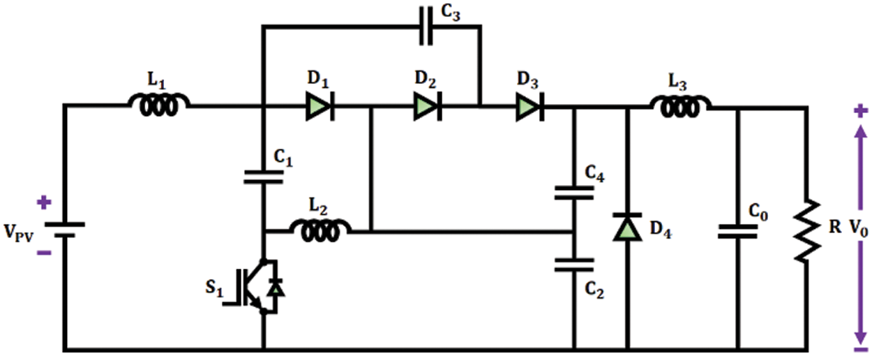
Figure 2: TZSBLC circuit diagram
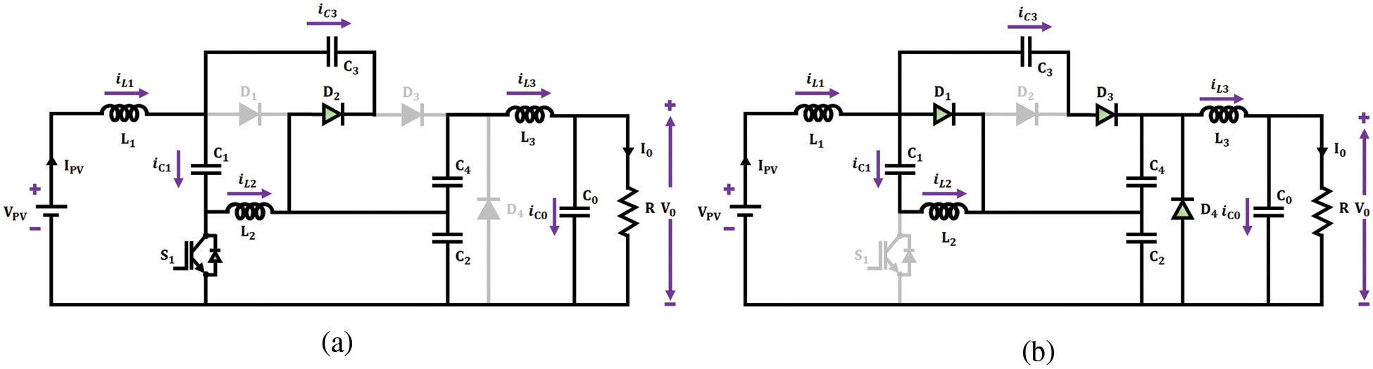
Figure 3: Circuit diagrams of (a) Mode 1 and (b) Mode 2 operation
The power switch
The power switch
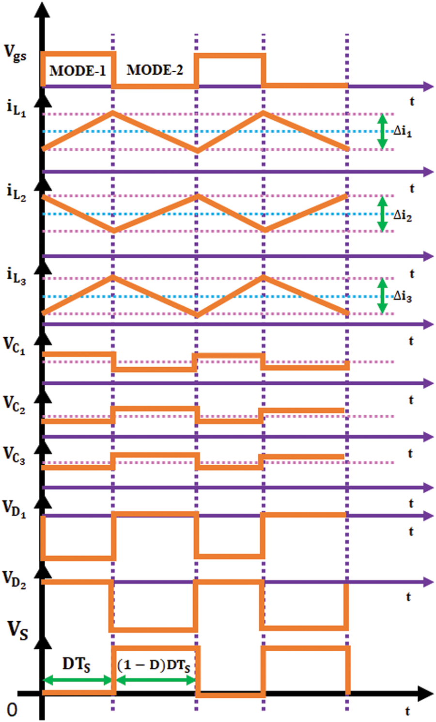
Figure 4: Current and voltage waveforms of TZSBLC
The value of the inductors
The
The value of the output capacitor is,
The unstable DC output voltage obtained from the converter is optimized and made stable with the assistance of LGWO-PI controller.
3.2 Lion Grey Wolf Optimized PI Controller
LGWO algorithm is a hybrid optimization algorithm that is designed by combining both Lion Swarm Optimization (LSO) and GWO algorithm. The proposed LGWO approach incorporates the hunting behaviour of lions and encircling behaviour of grey wolves in order to estimate the values of
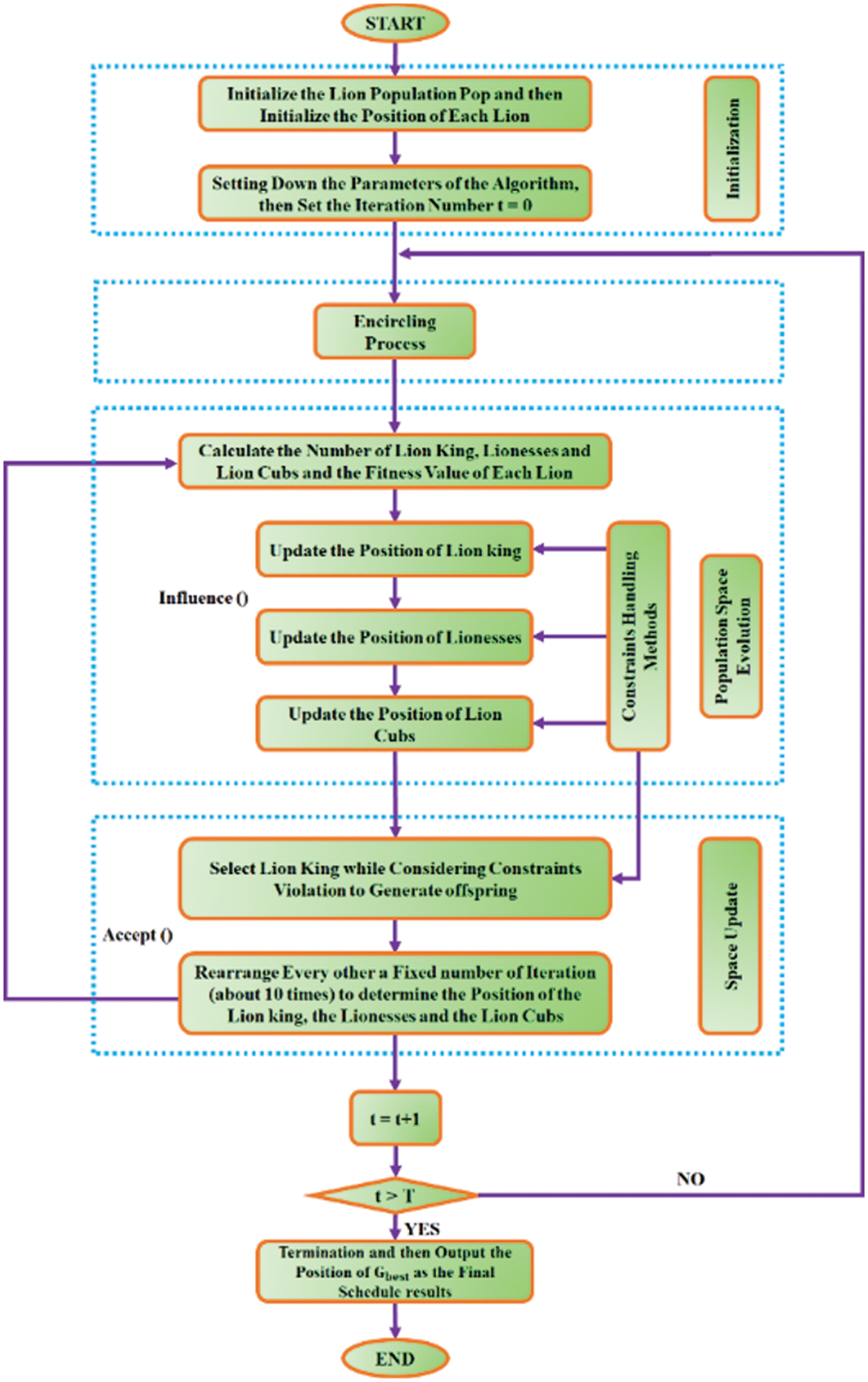
Figure 5: LGWO flowchart
The disturbance factor of lionesses
Here,
Here,
The value of the step in the activity range of lion cubs is specified as,
The term
The position of each lion in this algorithm signifies a feasible solution to the problem that has to be evaluated. The nature of prey relies on the quality (fitness) of the related solution. In the case of a D-dimensional GOP, an initial population P with n solutions are generated in a random manner in search space
Here, the j-th dimension of i-th lion is specified by
The equation given below specifies the number of adult lions i.e., nLeader, which includes the lion king and lioness:
n-nLeader gives the number of lion cubs and the value of nLeader ranges from 2 to n/2.
The way the grey wolves encircles the prey is mathematically expressed as,
Here,
The values of coefficient vectors
Here,
When the user-defined fitness functions are substituted with the decision variable value i.e., solution vector, the fitness value of the position of every single lion is obtained as,
Little prey, normal prey and optimal prey are the quality of prey searched by the lion cubs, lioness and lion king, respectively. The f value indicates the quality of prey targeted by each lion.
Based on the experience of each lion and its neighbours, the location of each lion is adjusted. The lions follow different hunting methods to hunt the prey.
The lion king starts moving towards the location with the least fitness value (best food) to make sure that it has a higher priority for prey. The following equation specifies the lion king’s new position,
Here, t denotes the current iteration value,
The typical hunting behaviour of lioness is to locate the prey, encircle it and then attack the prey. The lioness hunts its prey in cooperation with another lioness. The lionesses’ new position is expressed as,
At current iteration,
There are three possibilities during the vibrant hunting of lion cubs and the following equation specifies the lion cubs’ new position as,
Here, q specifies a random number among 0 and 1. The position, in which
The LGWO parameters are clearly listed out in Tab. 1.
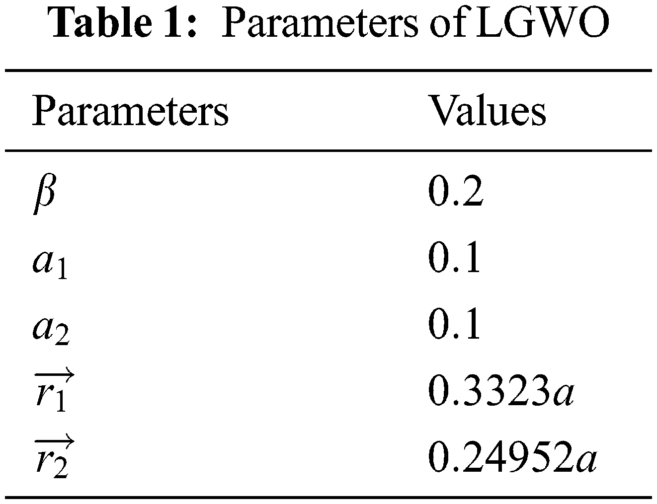

The pseudo code of this LGWO is evidently explained in the subsequent section in an efficient manner.
3.3 Mathematical Model of BLDC Motor
The stable and distortion free DC output voltage obtained from TZSBLC with the assistance of LGWO-PI controller is given to the 3φ VSI. The circuit and model of 3
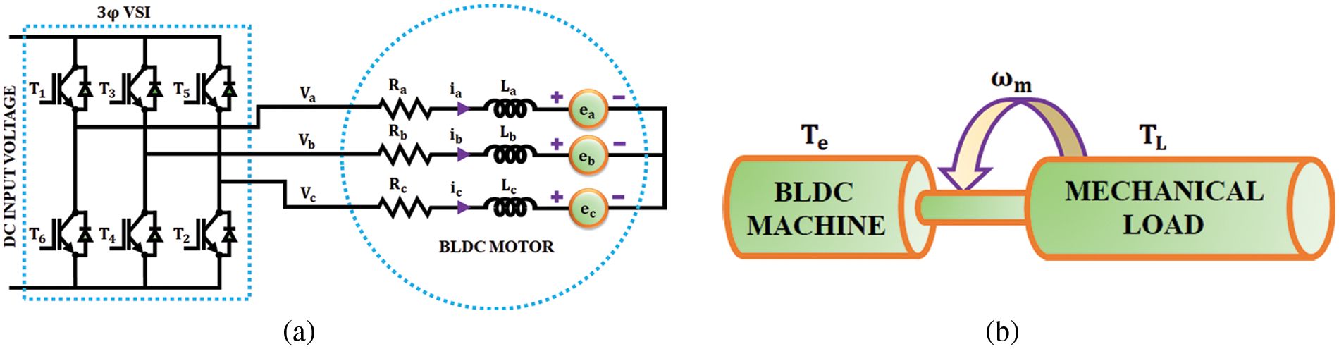
Figure 6: (a) Equivalent circuit (b) mechanical model
The 3φ star connected BLDC motor is represented using the subsequent equations,
The phase back emf, phase currents and phase-to-phase voltages are denoted by e,
The electrical torque is given as,
Here,
Here,
The trapezoidal waveform of the back emf is given by the function
By using the current Eq. (36), voltages specified in Eqs. (37) and (38) are obtained,
The entire model becomes,
To simplify and achieve better computational efficiency, the machine model is generally converted to a rotating reference frame.
The performance of the proposed PV based BLDC motor with TZSBLC and LGWO-PI controller is examined using MATLAB simulation and the outcomes are evidently discussed in this section. The solar panel, TZSBLC and BLDC motor parameters are specified in Tab. 2 whereas the gain values of PI controller are specified in Tab. 3.
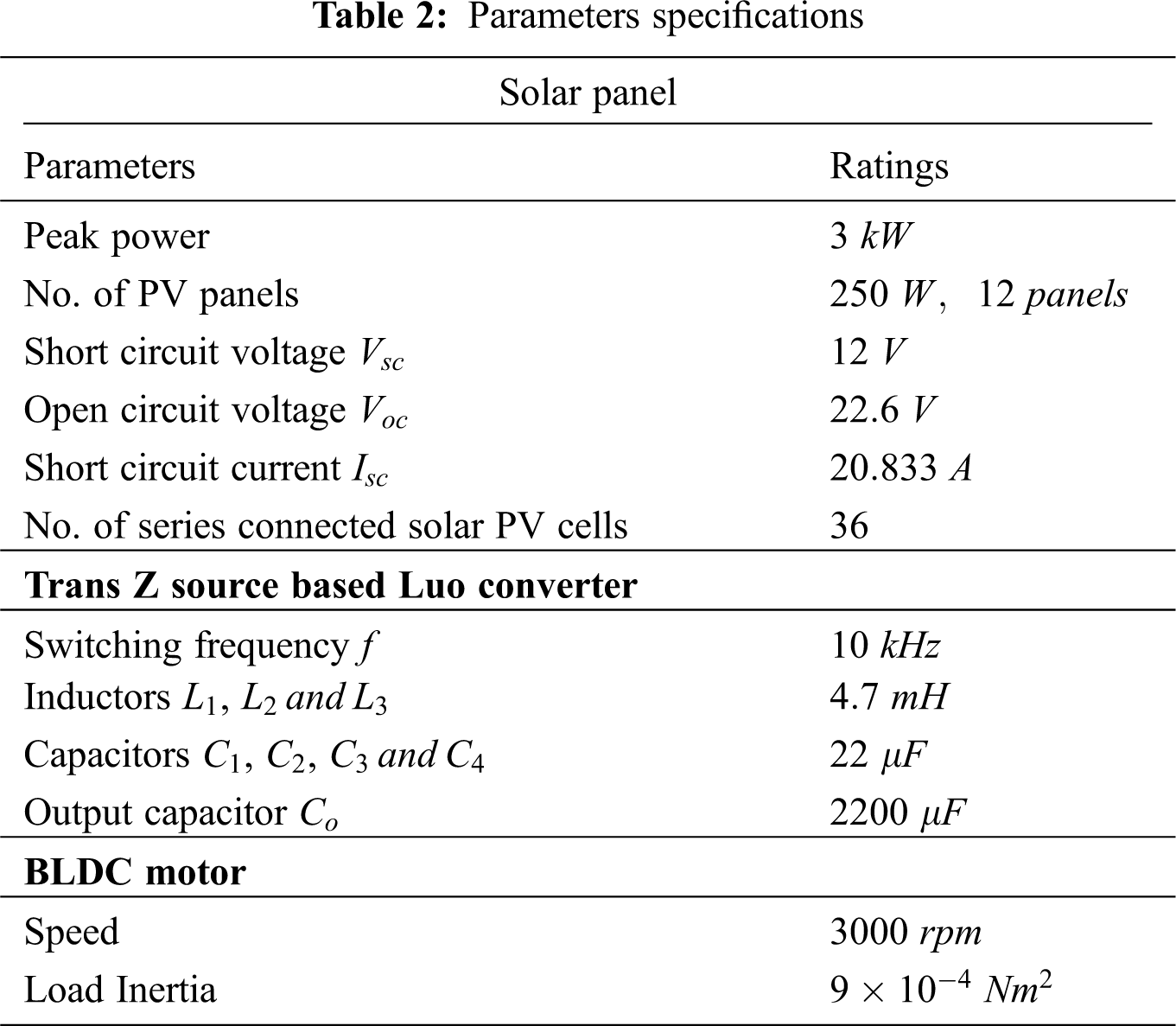
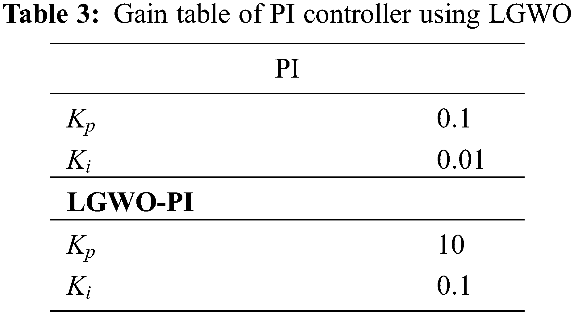
Fig. 7 illustrates the solar PV panel temperature, voltage, current and power waveforms. For analyzing the effectiveness of the introduced methodology in overcoming the non-linearity of PV system, the operating condition is altered in the form of temperature variation. The temperature is constantly maintained at
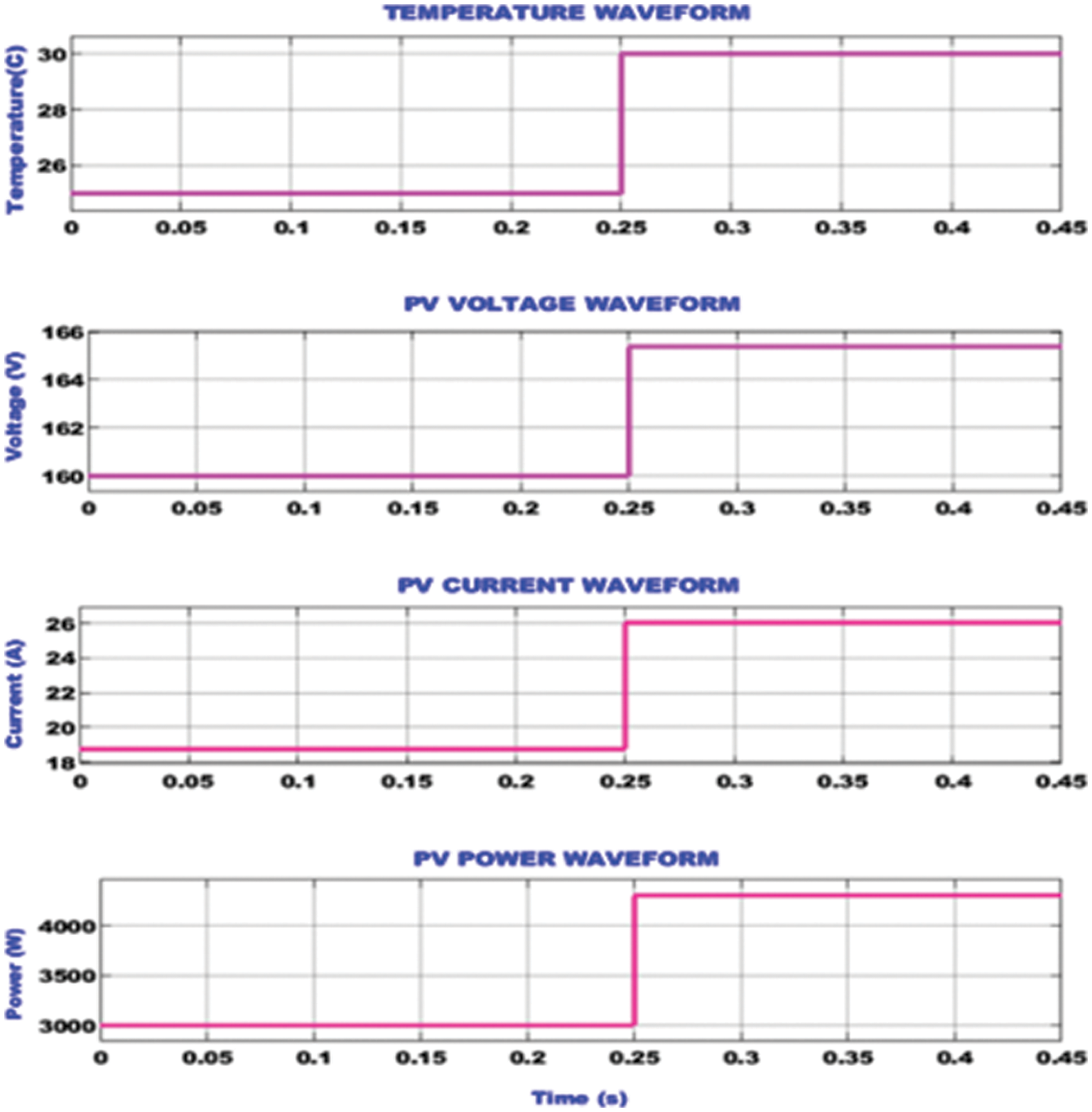
Figure 7: Waveforms of solar PV panel input and output variables
The simulation waveforms used to ascertain the performance of the proposed TZSBLC, which comprises of its input voltage, output voltage using PI controller and output voltage using optimized PI is illustrated in Fig. 8. The PV output is provided as input to the TZSBLC. Due to influence of change in temperature, the PV voltage increases from 160 to 165.6 V at 0.25 s. The PI controller is not effective in enhancing the operation of the TZSBLC since the converter output voltage is not constant. However, the proposed hybrid LGWO based PI controller displays remarkable performance in stabilizing the TZSBLC output by providing a constant voltage of 340 V from 0.05 s. The proposed hybrid optimization technique also significantly overcomes the impact of change in temperature.
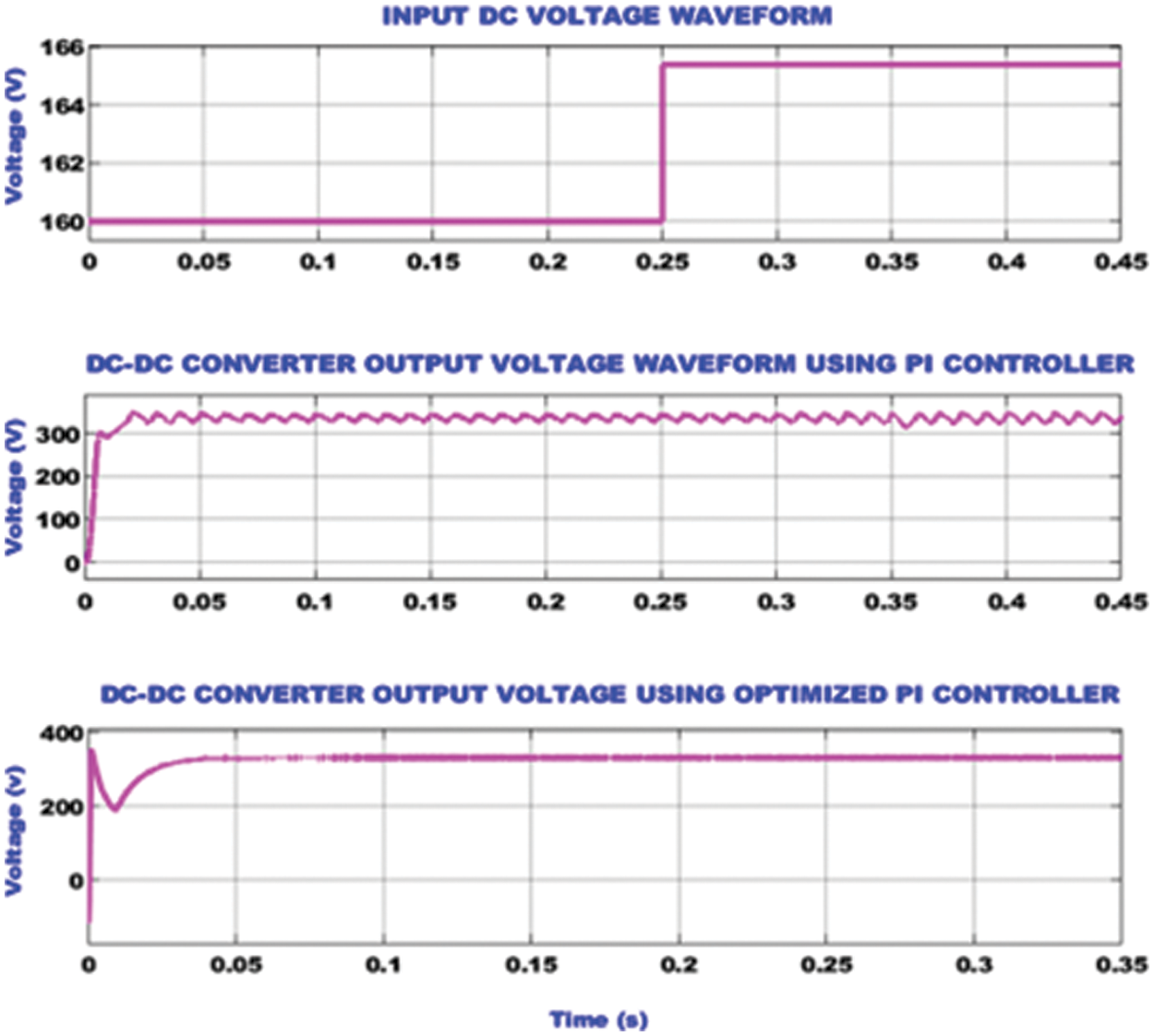
Figure 8: TZSBLC waveforms representing the input voltage, output voltage using PI controller and output voltage using optimized PI controller
The grid side waveforms for the developed EV charging system is portrayed in Fig. 9. The constant AC voltage and current of magnitude 230 V and current 10 A, respectively are maintained in the grid. After the disturbances at initial stage, the value of real power increases to reach a steady value of 1000 W from 0.1 s. The reactive power magnitude reaches a peak value of 2900 VAR at 0.025 s and then it becomes a near zero value at 0.1 s.
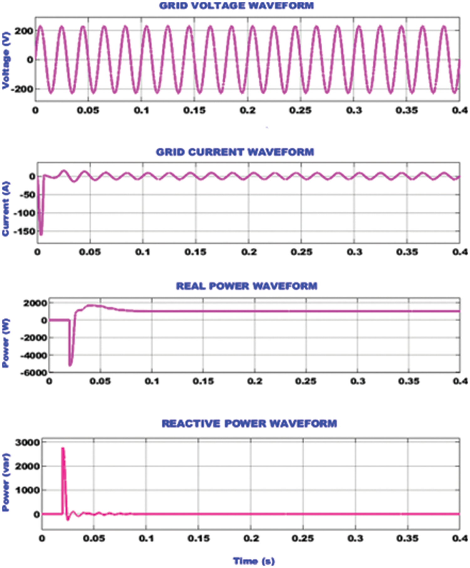
Figure 9: Grid side waveforms representing the voltage, current, real power and reactive power
The waveforms representing the current, back emf, speed and torque of the BLDC motor are depicted in Fig. 10. The above waveforms are used to analyse the operation of BLDC motor under variable speed conditions. The speed of the motor is initially around 1500 rpm till 0.35 s and then it is increased to 2000 rpm at 0.36 s. The impact of the speed variation is seen in the current, back emf and torque waveforms of the motor. At 0.36 s, the motor current raises from 5 to 15 A and then recovers to provide a steady output of 5 A again. Similarly, the motor torque also experiences an abrupt increase at 0.36 s from 2 to 11 Nm and again recovers quickly to 2 Nm. The back emf of the motor increases with the increase in speed at 0.36 s from 60 to 80 V.
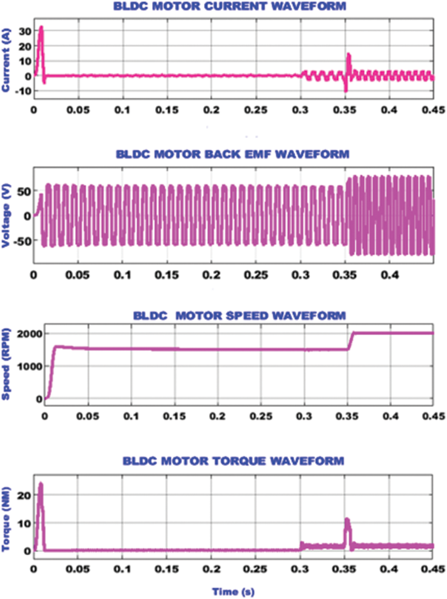
Figure 10: BLDC motor waveforms under variable speed
The BLDC motor parameter waveforms under constant speed condition is seen in Fig. 11. The speed of the BLDC motor is not varied and maintained to be constant at a speed of 1500 rpm from 0.02 s. The BLDC motor current, which is zero in the beginning gets raised to a magnitude of 5 A from 0.3 s. Since the motor is running with a constant speed, the back emf is also maintained at a constant value of 60 V. Similar to the motor current, the torque also becomes 2 Nm from 0.3 s.
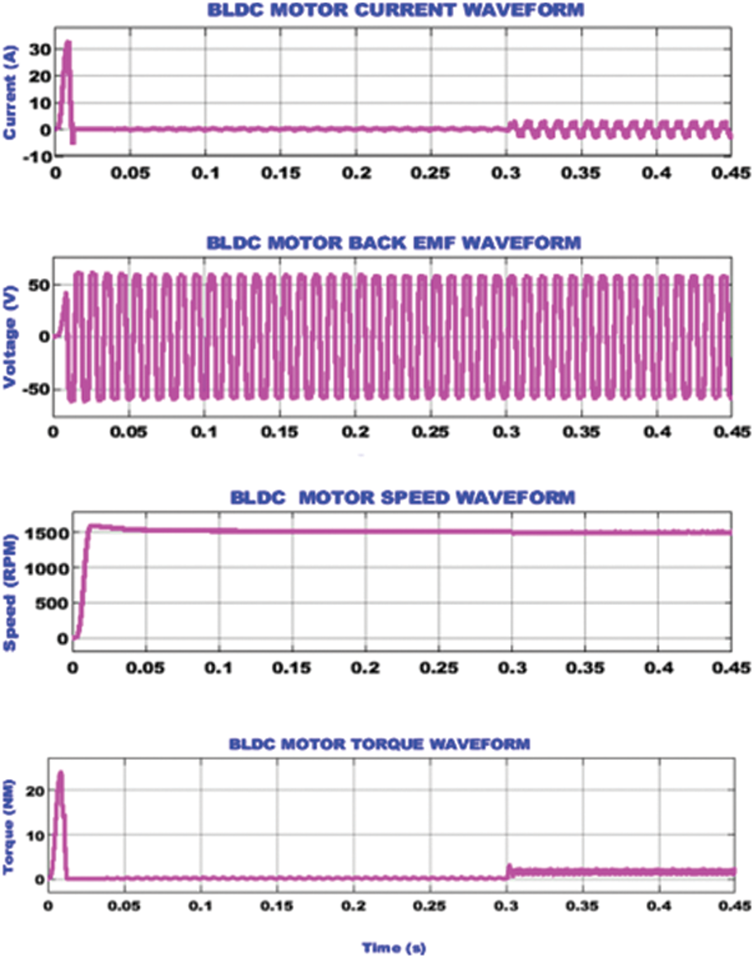
Figure 11: BLDC motor waveforms under constant speed
The hardware analysis of the proposed grid tied solar EV charging system developed with the assistance of TZSBLC is implemented with the assistance of FPGA Spartan 6 E controller and the obtained outcomes are analyzed in detail subsequently. The hardware prototype is clearly portrayed in Fig. 12 in an optimal manner.
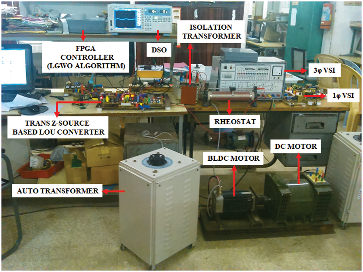
Figure 12: Hardware prototype
The hardware results representing the voltage and current output derived from the PV is given in Fig. 13. The PV output gets improved with the raise of temperature. The output current derived from the PV remains stable with slight fluctuations.
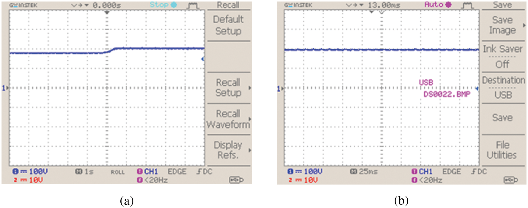
Figure 13: PV system (a) voltage and (b) current waveforms
The waveforms representing the output voltage of the TZSBLC with optimization and without optimization is given in Fig. 14. Without the aid of optimization, the converter output is affected by peak overshoot conditions as indicated from the figure but the problem of peak overshoot condition is eliminated and a stable output of 330 V is obtained with the aid of suitable optimization technique.
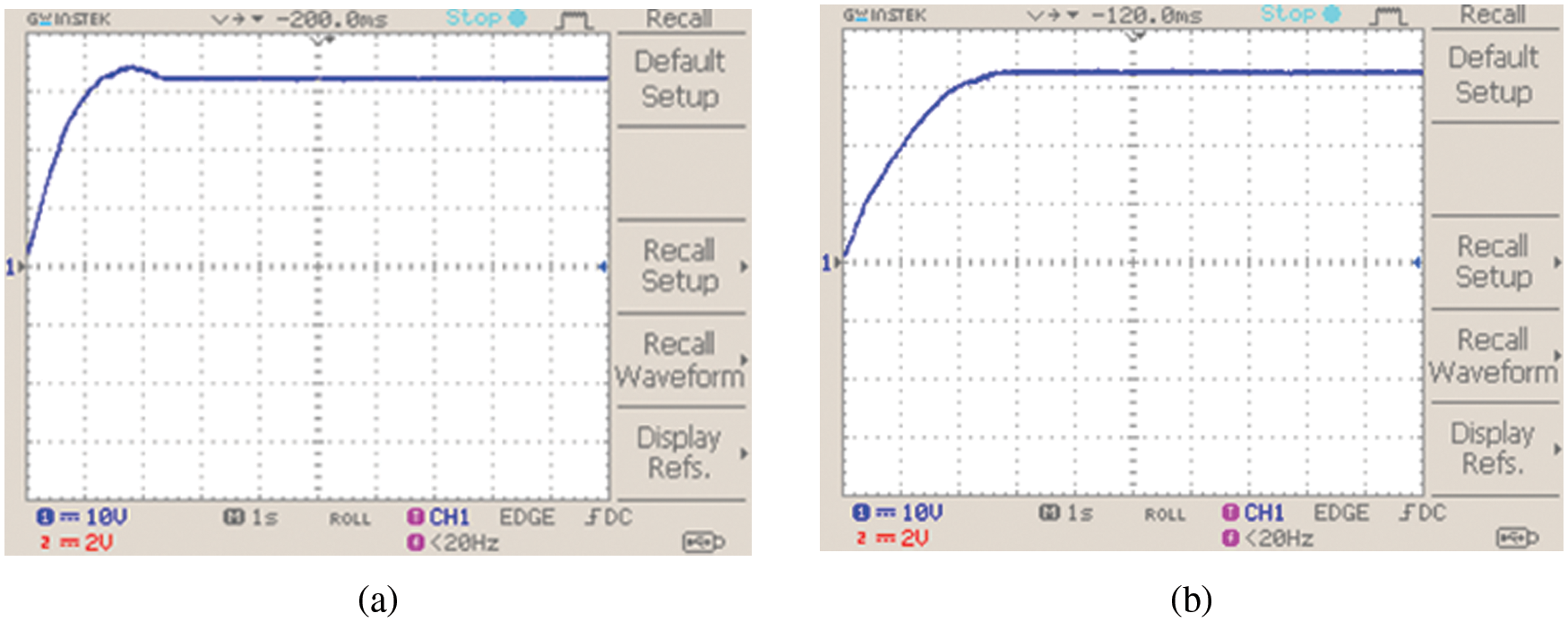
Figure 14: TZSBLC output voltage (a) without optimization and (b) with optimization
The BLDC motor’s reference speed is set to 1500 rpm. After the application of the proposed hybrid optimized controller, the speed remains stable and it is effectively regulated as illustrated in Fig. 15b. The reference and actual speeds are respectively highlighted in blue and red colours. The Fig. 15a represents the BLDC motor’s speed response characteristics without the application of optimization controller.
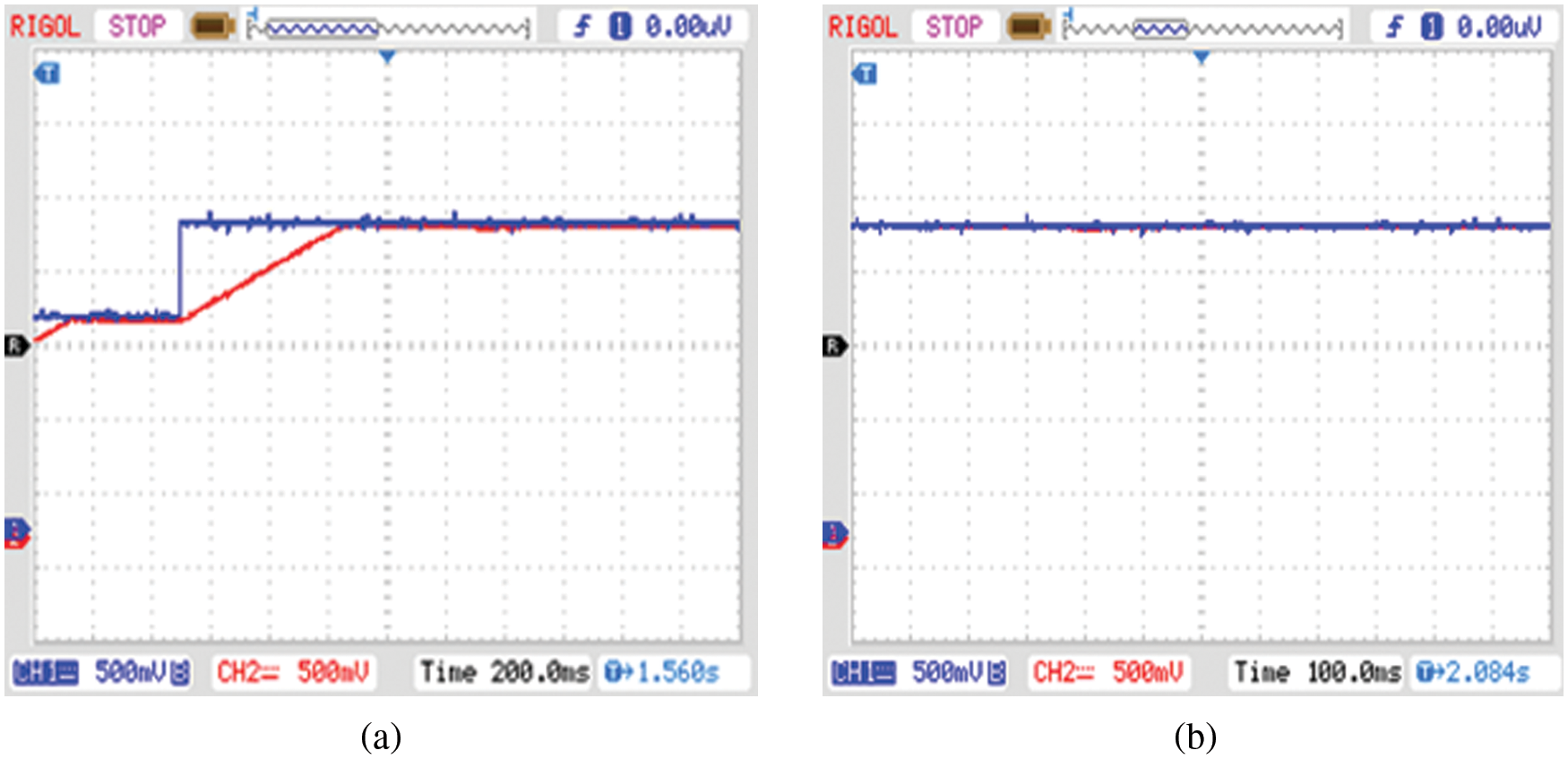
Figure 15: Speed waveform (at 1500 rpm) (a) without optimization controller and (b) with optimization controller
The BLDC motor’s speed and torque are effectively regulated and maintained stable without peak over shoot issues by using the proposed closed loop speed control technique as specified in the Fig. 16.
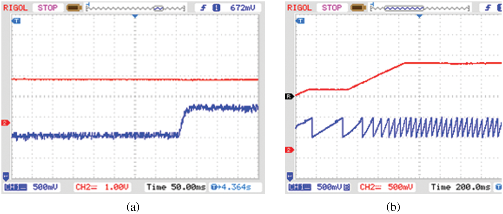
Figure 16: (a) Speed and (b) torque waveform
By using the PI controller, effective grid voltage synchronization is achieved so that a constant 230 V AC supply is fed to the grid from the inverter as represented in Fig. 17.
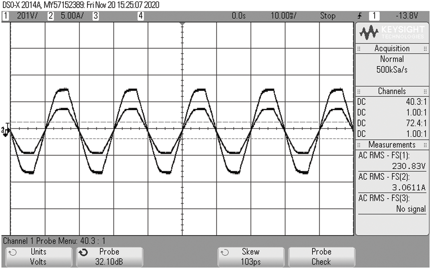
Figure 17: Grid voltage and current waveforms
The proposed trans Z-Source based Luo converter voltage gain is compared with other existing converetes such as Boost, Cuk, SEPIC and Luo as represented in Fig. 18a, which illustrates that the proposed converter owns optimum voltage gain than the other converters as it delivers high gain ratio of
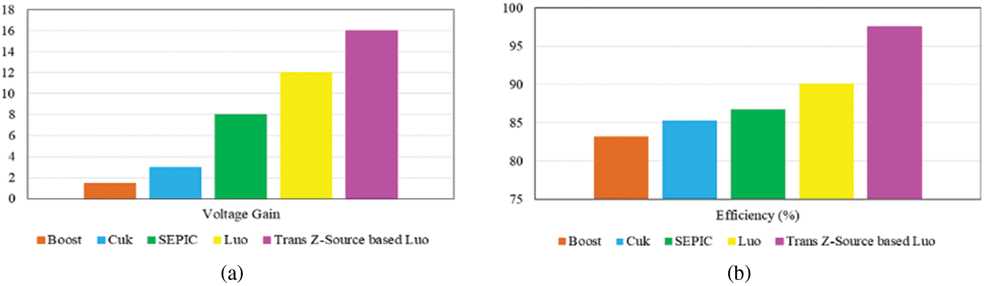
Figure 18: Comparative analysis of (a) voltage gain (b) efficiency
The efficiency is the significant parameter in analysing the performance of the converter and so the efficiency of the Trans Z-Source based Luo converter is analogised with other conventional converters that are specified in the aforementioned section. As represented in Fig. 18b, the outcome of this comparative analysis validates that the introduced converter provides maximum efficiency of 97.6% that is extremely optimal than the other converters that already exist.
The introduced controller takes less settling time of
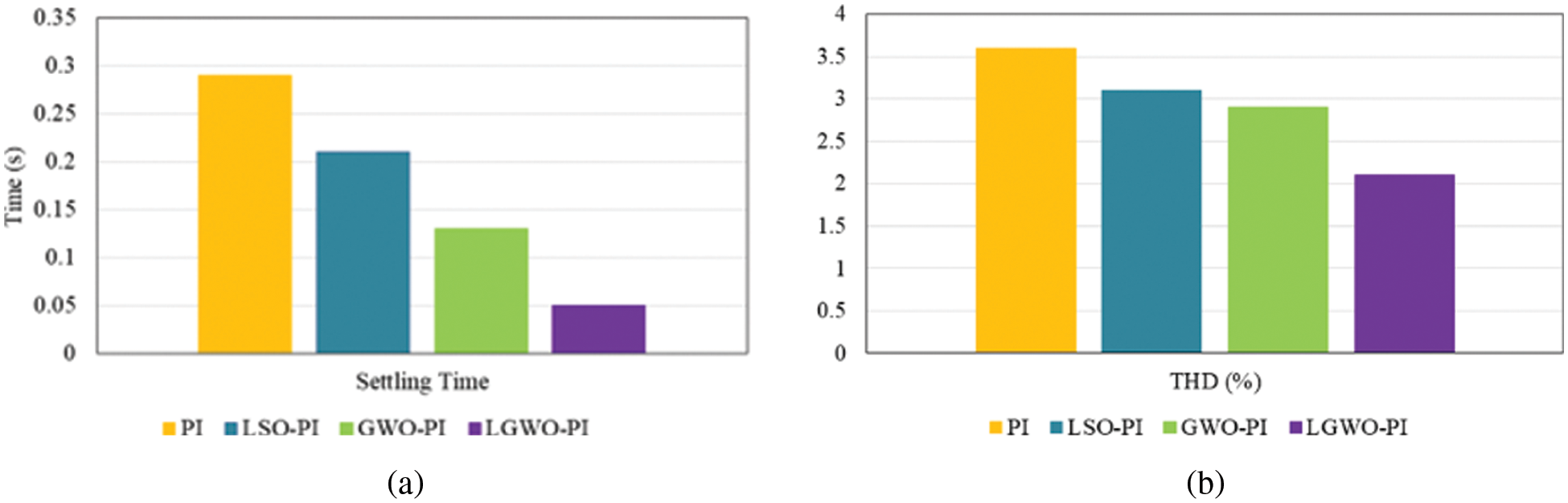
Figure 19: Comparison of (a) settling time (b) THD
The attained THD using the introduced LGWO-PI controller is analogized with other controllers like PI, LSO-PI and GWO-PI controllers as highlighted through the graphical representation in Fig. 19b. It validates that the proposed controller involves in minimizing the harmonic distortions in a wider range as it attain less THD of 2.1%, which is comparatively lower than the other controllers.
A novel robust hybrid LGWO-PI controller is designed with the objective of bringing significant enhancement to the operation of PV system, which is the major source of power supply in the proposed EV charging station. The development of an optimal control methodology for grid tied solar EV charging station aims towards boosting the adoption of EVs in addition to minimizing the over dependency on grid. The control approach proposed in this work for stabilizing and improving the output from the PV system includes a high gain TZSBLC and hybrid LGWO-PI controller. The selected BLDC motor drive for EVs offers excellent speed regulation, high efficiency in addition to less maintenance requirement. The reliability of the charging station is ensured with the inclusion of
Funding Statement: The authors received no specific funding for this study.
Conflicts of Interest: The authors declare that they have no conflicts of interest to report regarding the present study.
References
1. A. Zahedmanesh, K. M. Muttaqi and D. Sutanto, “A cooperative energy management in a virtual energy hub of an electric transportation system powered by PV generation and energy storage,” IEEE Transactions on Transportation Electrification, vol. 7, no. 3, pp. 1123–1133, 2021. [Google Scholar]
2. A. Mohammad, R. Zamora and T. T. Lie, “Transactive energy management of PV-based EV integrated parking lots,” IEEE Systems Journal, vol. 15, no. 4, pp. 5674–5682, 2021. [Google Scholar]
3. A. Verma and B. Singh, “Multimode operation of solar PV array, grid, battery and diesel generator set based EV charging station,” IEEE Transactions on Industry Applications, vol. 56, no. 5, pp. 5330–5339, 2020. [Google Scholar]
4. Q. Chen, F. Wang, B. M. Hodge, J. Zhang, Z. Li et al., “Dynamic price vector formation model-based automatic demand response strategy for PV-assisted EV charging stations,” IEEE Transactions on Smart Grid, vol. 8, no. 6, pp. 2903–2915, 2017. [Google Scholar]
5. J. Liu, J. Wu, J. Qiu and J. Zeng, “Switched Z-source/quasi-Z-source DC-DC converters with reduced passive components for photovoltaic systems,” IEEE Access, vol. 7, pp. 40893–40903, 2019. [Google Scholar]
6. K. Kumar, N. Ramesh Babu and K. R. Prabhu, “Design and analysis of RBFN-based single MPPT controller for hybrid solar and wind energy system,” IEEE Access, vol. 5, pp. 15308–15317, 2017. [Google Scholar]
7. N. Rana and S. Banerjee, “Development of an improved input-parallel output-series buck-boost converter and its closed-loop control,” IEEE Transactions on Industrial Electronics, vol. 67, no. 8, pp. 6428–6438, 2020. [Google Scholar]
8. J. C. D. S. de Morais, J. L. D. S. de Morais and R. Gules, “Photovoltaic AC module based on a cuk converter with a switched-inductor structure,” IEEE Transactions on Industrial Electronics, vol. 66, no. 5, pp. 3881–3890, 2019. [Google Scholar]
9. K. S. Tey, S. Mekhilef, M. Seyedmahmoudian, B. Horan, A. T. Oo et al., “Improved differential evolution-based MPPT algorithm using SEPIC for PV systems under partial shading conditions and load variation,” IEEE Transactions on Industrial Informatics, vol. 14, no. 10, pp. 4322–4333, 2018. [Google Scholar]
10. R. Kumar and B. Singh, “BLDC Motor-driven solar PV array-fed water pumping system employing zeta converter,” IEEE Transactions on Industry Applications, vol. 52, no. 3, pp. 2315–2322, 2016. [Google Scholar]
11. M. Forouzesh, Y. Shen, K. Yari, Y. P. Siwakoti and F. Blaabjerg, “High-efficiency high step-up DC–DC converter with dual coupled inductors for grid-connected photovoltaic systems,” IEEE Transactions on Power Electronics, vol. 33, no. 7, pp. 5967–5982, 2018. [Google Scholar]
12. M. Das, M. Pal and V. Agarwal, “Novel high gain, high efficiency DC–DC converter suitable for solar PV module integration with three-phase grid tied inverters,” IEEE Journal of Photovoltaics, vol. 9, no. 2, pp. 528–537, 2019. [Google Scholar]
13. K. Nathan, S. Ghosh, Y. Siwakoti and T. Long, “A new DC–DC converter for photovoltaic systems: Coupled-inductors combined CUK-SEPIC converter,” IEEE Transactions on Energy Conversion, vol. 34, no. 1, pp. 191–201, 2019. [Google Scholar]
14. B. Singh and R. Kushwaha, “Power factor preregulation in interleaved luo converter-fed electric vehicle battery charger,” IEEE Transactions on Industry Applications, vol. 57, no. 3, pp. 2870–2882, 2021. [Google Scholar]
15. S. N. Singh, “Selection of non–isolated DC-DC converters for solar photovoltaic system,” Renewable and Sustainable Energy Reviews, vol. 76, pp. 1230–1247, 2017. [Google Scholar]
16. M. Mohammadi, J. S. Moghani and J. Milimonfared, “A novel dual switching frequency modulation for Z-source and quasi-Z-source inverters,” IEEE Transactions on Industrial Electronics, vol. 65, no. 6, pp. 5167–5176, 2018. [Google Scholar]
17. X. Ding, Y. Liu, D. Zhao and W. Wu, “Generalized cockcroft-walton multiplier voltage Z-source inverters,” IEEE Transactions on Power Electronics, vol. 35, no. 7, pp. 7175–7190, 2020. [Google Scholar]
18. T. Sreekanth, N. Lakshminarasamma and M. K. Mishra, “A Single-stage grid-connected high gain buck–boost inverter with maximum power point tracking,” IEEE Transactions on Energy Conversion, vol. 32, no. 1, pp. 330–339, 2017. [Google Scholar]
19. M. S. Ali, L. Wang, H. Alquhayz, O. U. Rehman and G. Chen, “Performance improvement of three-phase boost power factor correction rectifier through combined parameters optimization of proportional-integral and repetitive controller,” IEEE Access, vol. 9, pp. 58893–58909, 2021. [Google Scholar]
20. F. A. Alturki, H. O. Omotoso, A. A. Al-Shamma’a, H. M. H. Farh and K. Alsharabi, “Novel manta rays foraging optimization algorithm based optimal control for grid-connected PV energy system,” IEEE Access, vol. 8, pp. 187276–187290, 2020. [Google Scholar]
21. K. Y. Ahmed, N. Z. Bin Yahaya, V. S. Asirvadam, N. Saad, R. Kannan et al., “Development of power electronic distribution transformer based on adaptive PI controller,” IEEE Access, vol. 6, pp. 44970–44980, 2018. [Google Scholar]
22. M. H. Qais, H. M. Hasanien and S. Alghuwainem, “A grey wolf optimizer for optimum parameters of multiple PI controllers of a grid-connected PMSG driven by variable speed wind turbine,” IEEE Access, vol. 6, pp. 44120–44128, 2018. [Google Scholar]
23. M. I. Mosaad, H. S. M. Ramadan, M. Aljohani, M. F. El-Naggar and S. S. M. Ghoneim, “Near-optimal PI controllers of STATCOM for efficient hybrid renewable power system,” IEEE Access, vol. 9, pp. 34119–34130, 2021. [Google Scholar]
24. A. Ahmad, S. A. R. Kashif, A. Nasir, A. Rasool, S. Liaquat et al., “Controller parameters optimization for multi-terminal DC power system using ant colony optimization,” IEEE Access, vol. 9, pp. 59910–59919, 2021. [Google Scholar]
25. A. M. Hussien, R. A. Turky, A. Alkuhayli, H. M. Hasanien, M. Tostado-Véliz et al., “Coot bird algorithms–based tuning PI controller for optimal microgrid autonomous operation,” IEEE Access, vol. 10, pp. 6442–6458, 2022. [Google Scholar]
26. Y. Sun, S. Li, B. Lin, X. Fu, M. Ramezani et al., “Artificial neural network for control and grid integration of residential solar photovoltaic systems,” IEEE Transactions on Sustainable Energy, vol. 8, no. 4, pp. 1484–1495, 2017. [Google Scholar]
27. C. Zheng, T. Dragičević, Z. Zhang, J. Rodriguez and F. Blaabjerg, “Model predictive control of LC–filtered voltage source inverters with optimal switching sequence,” IEEE Transactions on Power Electronics, vol. 36, no. 3, pp. 3422–3436, 2021. [Google Scholar]
Cite This Article
 Copyright © 2023 The Author(s). Published by Tech Science Press.
This work is licensed under a Creative Commons Attribution 4.0 International License , which permits unrestricted use, distribution, and reproduction in any medium, provided the original work is properly cited.
 Downloads
 Citation Tools